

Page 1
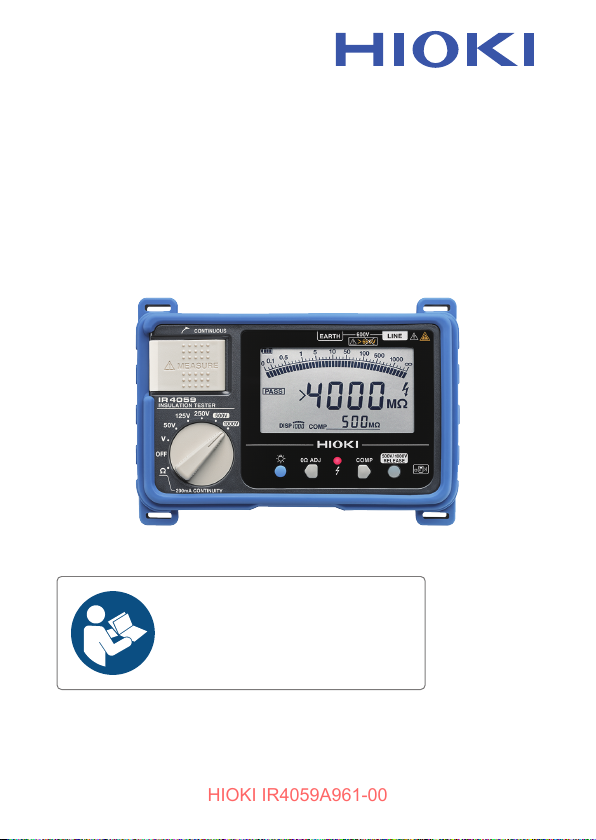
IR4059
HIOKI IR4059A961-00
Instruction Manual
INSULATION TESTER
Read carefully before use.
Keep for future reference.
Dec. 2023 Edition 1
IR4059A961-00
EN
[600654130]
Page 2

HIOKI IR4059A961-00
Page 3
Contents
HIOKI IR4059A961-00
Introduction .........................................................................5
Verifying Package Contents ..............................................6
Options ................................................................................ 7
Notations ........................................................................... 10
Safety Information ............................................................ 13
Operating Precautions ..................................................... 15
1 Overview 19
1.1 Product Overview .......................................... 19
1.2 Names and Functions of Parts ....................20
2 Preparing for Measurement 25
2.1 Protector ........................................................26
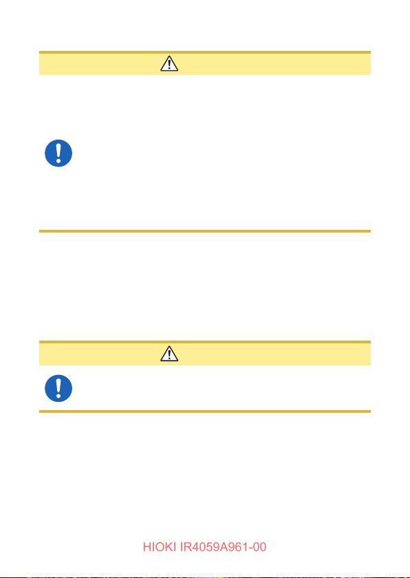
2.2 Replacing Batteries or Fuse ......................... 27
2.3 Using the L9788-10 Test Lead with
Remote Switch (Red) ....................................31
2.4 Installing the Z3210 Wireless Adapter .........33
3 Measurement 35
3.1 Pre-measurement Inspection ....................... 35
3.2 Auto Power Save (Power-Saving Function) 36
3.3 Auto Backlight-off (Automatic Light-off
Function) ........................................................ 37
3.4 Comparator Function .................................... 38
Setting the Comparator ............................................. 39
Canceling the Comparator ........................................ 40
3.5 Insulation Resistance Measurement ........... 41
Lock Function ...........................................................42
Measuring Insulation Resistance .............................. 43
Appx.
IR4059A961-00
3
Page 4
Contents
HIOKI IR4059A961-00
Displaying 1-minute Values....................................... 44
Voltage Characteristics of Measurement Terminals ..45
3.6 Discharging Function ...................................46
3.7 Voltage Measurement ................................... 47
3.8 Low Resistance Measurement ..................... 48
3.9 Wireless Communications Function .......... 50
Using the GENNECT Cross ...................................... 50
Excel Direct Input Function (HID function) ................ 54
4 Specications 57
4.1 GeneralSpecications .................................57
4.2 BasicandAccuracySpecications .............59
4.3 Functionalityspecications ......................... 67
Power-on Options ..................................................... 71
4.4 OtherSpecications .....................................72
5 Maintenance and Service 73
5.1 Troubleshooting ............................................75
Errors and status codes ............................................ 80
Appendix Appx.1
Appx. 1 Measurement Principles .................. Appx.1
Appx. 2 Operation Uncertainty ...................... Appx.2
WarrantyCerticate
4
Page 5
Introduction
HIOKI IR4059A961-00
Introduction
Thank you for choosing the Hioki IR4059 Insulation Tester. To
ensure your ability to get the most out of this instrument over the
long term, please read this manual carefully and keep it available for
future reference.
Hereinafter, the descriptions refer to models as shown on the
instrument.
The latest edition of the instruction manual
The contents of this manual are subject to change, for
example as a result of product improvements or changes
to specications.
The latest edition can be downloaded from Hioki's website.
https://www.hioki.com/global/support/download/
Product registration
Register your product in order to receive important product
information.
https://www.hioki.com/global/support/myhioki/registration/
Intended audience
This manual has been written for use by individuals who use the
product or provide information about how to use the product.
In explaining how to use the product, it assumes electrical
knowledge (equivalent of the knowledge possessed by a graduate
of an electrical program at a technical high school).
5
Page 6

Verifying Package Contents
HIOKI IR4059A961-00
Verifying Package Contents
When you receive the instrument, inspect it carefully to ensure that no
damage occurred during shipping. In particular, check the accessories,
panel switches, and connectors. If damage is evident, or if it fails to
operate according to the specications, contact your authorized Hioki
distributor or reseller. Conrm that these contents are provided.
IR4059 Insulation Tester
L4930 Connection Cable Set
L4935 Alligator Clip Set
L4938 Test Pin Set
L9788-10 Test Lead with Remote Switch (Red)
Z5042 Protector
Neck strap
LR6 Alkaline battery ×4
Instruction Manual
Operating Precautions (0990A907)
6
Page 7
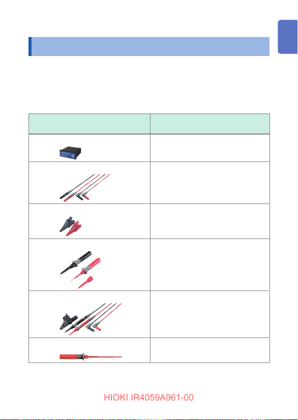
Options
HIOKI IR4059A961-00
Options
The options listed below are available for the instrument. To order
an option, please contact your authorized Hioki distributor or
reseller.
Options are subject to change. Please check Hioki's website for the
latest information.
Model
Z3210 Wireless Adapter
L4930 Connection Cable Set (1.2 m)
Maximum rated voltage and
maximum rated current
–
CAT IV 600 V/CAT III 1000 V
10 A
L4935 Alligator Clip Set
L4938 Test Pin Set
L9787 Test Lead (1.2 m)
L9787-91 Breaker Pin
CAT IV 600 V/CAT III 1000 V
10 A
CAT III 600 V/CAT II 600 V
10 A
CAT III 600 V/CAT II 600 V
10 A
CAT III 600 V
10 A
7
Page 8
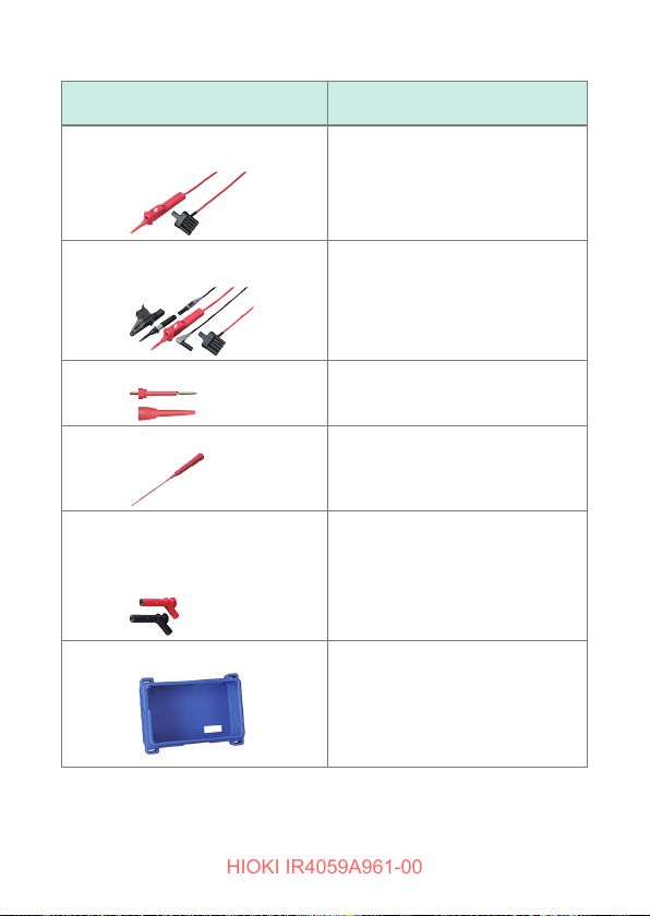
Options
HIOKI IR4059A961-00
Model
L9788-10 Test Lead with Remote
Switch (Red)
L9788-11 Test Lead Set with Remote
Switch
L9788-90 Tip Pin
L9788-92 Breaker Pin
9804-01 Magnetic Adapter (Red)
9804-02 Magnetic Adapter (Black)
(φ11 mm, standard screw: M6 pan
head screw)
Z5042 Protector
Maximum rated voltage and
maximum rated current
CAT III 600 V/CAT II 600 V
2 A
CAT III 600 V/CAT II 600 V
2 A
CAT III 600 V/CAT II 600 V
2 A
CAT III 600 V
2 A
CAT IV 1000 V
2 A
8
Page 9
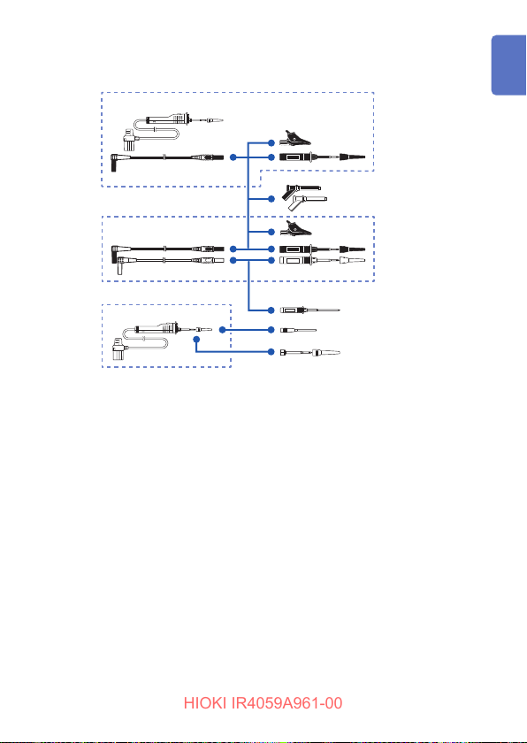
Test Lead
HIOKI IR4059A961-00
L9788-11
L9787
Options
9804-01
9804-02
L9788-10
L9787-91
L9788-92
L9788-90
9
Page 10
Notations
HIOKI IR4059A961-00
Notations
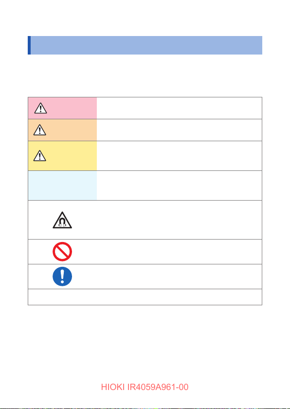
Safety notations
In this document, the severity levels of risk and hazard are classied
as follows.
DANGER
WARNING
CAUTION
IMPORTANT
Indicates an imminently hazardous situation that will
result in death or serious injury to the operator.
Indicates a potentially hazardous situation that may
result in death or serious injury to the operator.
Indicates a potentially hazardous situation that may
result in minor or moderate injury to the operator or
damage to the instrument or malfunction.
Indicates information or content that is particularly
important from the standpoint of operating or
maintaining the instrument.
Indicates a strong magnetic-eld hazard.
The effects of the magnetic force can cause
abnormal operation of heart pacemakers and/or
medical electronics.
Indicates prohibited actions.
Indicates the action which must be performed.
*
10
Additional information is presented below.
Page 11
Notations
HIOKI IR4059A961-00
Symbols on the instrument
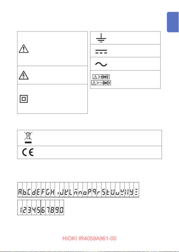
Indicates cautions and
hazards. When the symbol
is printed on the instrument,
refer to a corresponding
topic in the Instruction
Manual.
Indicates that dangerous
voltage may be present at
this terminal.
Indicates a instrument
that has been protected
throughout by double
insulation or reinforced
insulation.
Indicates a grounding
terminal.
Indicates DC (Direct
Current).
Indicates AC
(Alternating Current).
Do not use in distribution
systems with voltage
higher than 660 V AC.
Symbols for various standards
Indicates the Waste Electrical and Electronic Equipment
Directive (WEEE Directive) in EU member states.
Indicates that the product conforms to regulations set out by the
EU Directive.
Screen Display
The instrument screen displays the alphanumeric characters as follows.
A B C D E F G H I J K L M N O P Q R S T U V W X Y Z
1 2 3 4 5 6 7 8 9 0
Accuracy
Hioki expresses accuracy as error limit values specied in terms of
11
Page 12
Notations
HIOKI IR4059A961-00
percentages of reading and digits.
Reading
(Displayed value)
Digits
(Resolution)
Refers to the displayed value of the measuring
instrument. The limit values of reading errors are
expressed in percent of reading (% of reading, % rdg).
Refers to the smallest change in the indication on the
digital measuring instrument, i.e., the numeral one in
the rightmost place. The limit values of digit errors are
expressed in terms of digits (dgt).
Trademarks
• The Bluetooth® word mark and logos are registered trademarks
owned by Bluetooth SIG, Inc. and any use of such marks by
Hioki E.E. Corporation is under license.
Other trademarks and trade names are those of their respective
owners.
• Excel is a trademark of the Microsoft group of companies.
12
Page 13
Safety Information
HIOKI IR4059A961-00
Safety Information
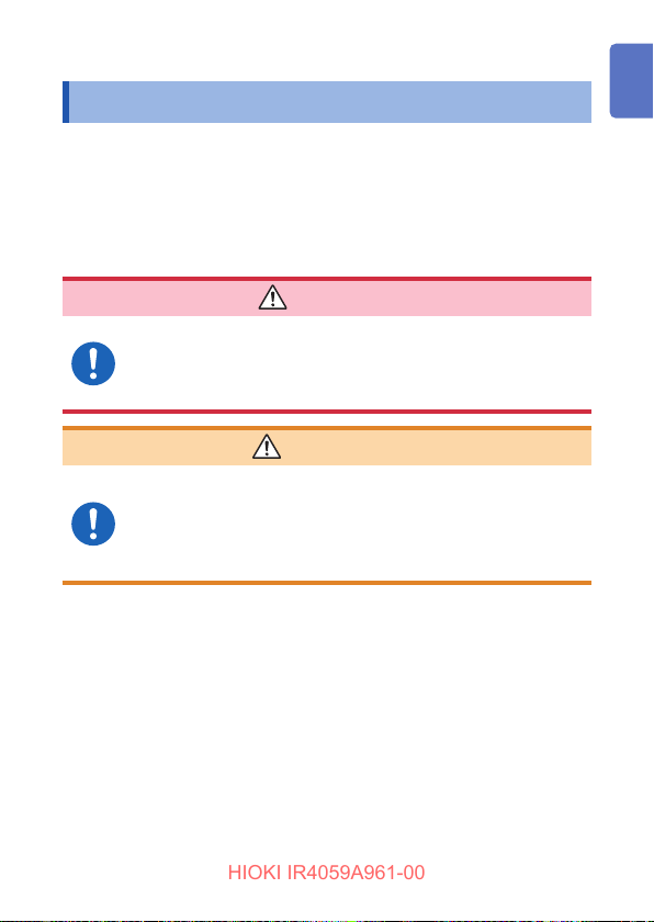
This instrument is designed to conform to IEC 61010 Safety
Standards, and has been thoroughly tested for safety prior to
shipment. However, using the instrument in a way not described in
this manual may negate the provided safety features.
Before using the instrument, be certain to carefully read the following
safety notes:
DANGER
Mishandling during use could result in injury or death,
as well as damage to the instrument. Be certain that
you understand the instructions and precautions in
the manual before use.
WARNING
Protective gear
Performing measurement using this instrument
involves live-line work. To prevent an electric shock,
use appropriate protective insulation and adhere to
applicable laws and regulations.
13
Page 14
Safety Information
HIOKI IR4059A961-00
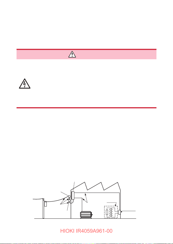
Measurement Categories
To ensure safe operation of measuring instruments, IEC 61010
establishes safety standards for various electrical environments,
categorized as CAT II to CAT IV, and called measurement categories.
DANGER
• Using a measuring instrument in an environment
designated with a higher-numbered category than
that for which the instrument is rated could result in
a severe accident, and must be carefully avoided.
• Never use a measuring instrument that lacks
category labeling in a CAT II to CAT IV measurement
environment. Doing so could result in a serious
accident.
This instrument conforms to the safety requirements for CAT III 600 V
measuring instruments.
CAT II: When directly measuring the electrical outlet receptacles of the
primary electrical circuits in equipment connected to an AC electrical
outlet by a power cord (portable tools, household appliances, etc.)
CAT III: When measuring the primary electrical circuits of heavy equipment
(xed installations) connected directly to the distribution panel, and
feeders from the distribution panel to outlets.
CAT IV:
When measuring the circuit from the service drop to the service
entrance, and to the power meter and primary overcurrent
protection device (distribution panel).
Service entrance
Service drop
14
Distribution panel
CAT IV
Power meter
Internal wiring
CAT III
Fixed installation
CAT II
T
Outlet
Page 15
Operating Precautions
HIOKI IR4059A961-00
Operating Precautions
Observe the following precautionary information to ensure that the
instrument can be used safely and in a manner that allows it to
perform as described in its specications.
Use of the instrument should conrm not only to its specications,
but also to the specications of all accessories, options, batteries,
and other equipment in use.
DANGER
• For your safe operation, do not connect any test
lead to the primary of the distribution panel.
• Do not short-circuit two wires to be measured by
bringing the test leads into contact with them. Arcs
or such grave accidents are likely to occur.
• To avoid short circuit or electric shock, do not touch
the metal part of the connecting test lead tip.
• To avoid electric shock, be careful to avoid shorting
live lines with the test leads tip.
If the test lead or the instrument is damaged, there
is a risk of electric shock. Perform the following
inspection before using them:
• Before using the instrument check that the coating
of the test leads are neither ripped nor torn and that
no metal parts are exposed. Using the instrument
under such conditions could result in electric
shock. Replace the test leads with those specied
by Hioki.
• Verify that the instrument operates normally to
ensure that no damage occurred during storage
or shipping. If you nd any damage, contact your
authorized Hioki distributor or reseller.
15
Page 16
Operating Precautions
HIOKI IR4059A961-00
WARNING
To avoid electric shock, short circuits and damage to
the instrument, observe the following precautions:
• Check the position of the rotary switch before
taking measurements.
• Disconnect the test leads from the measuring object
before switching the rotary switch.
• Do not use the instrument with circuits that exceed
its ratings or specications. Doing so may damage
the instrument, resulting in electric shock.
• Use only the specied test leads. Use of any test
lead not specied by Hioki does not allow safe
measurements.
• To prevent electrical accidents, turn off the circuit
before connecting the test leads.
• To avoid electric shock, do not exceed the lower of
the ratings shown on the instrument and test leads.
CAUTION
• The cable is hardened under the 0°C or colder
environment. Do not bend or pull it to avoid tearing its
shield or cutting cable.
• The protection rating for the enclosure of this device
(based on EN 60529) is IP40*.
* IP40:
This indicates the degree of protection provided by the enclosure of
the device against use in hazardous locations, entry of solid foreign
objects, and the ingress of water.
4: Protected against access to hazardous parts with wire measuring 1.0 mm
in diameter.
0: The equipment inside the enclosure is not protected against the harmful
effects of water.
16
Page 17
Operating Precautions
HIOKI IR4059A961-00
Installing the instrument
WARNING
Installing the instrument in inappropriate locations
may cause a malfunction of instrument or may give
rise to an accident. Avoid the following locations.
• Exposed to direct sunlight or high temperature
• Exposed to corrosive or combustible gases
• Exposed to a strong electromagnetic eld or
electrostatic charge
• Near induction heating systems (such as highfrequency induction heating systems and IH
cooking equipment)
• Susceptible to vibration
• Exposed to water, oil, chemicals, or solvents
• Exposed to high humidity or condensation
• Exposed to high quantities of dust particles
CAUTION
Do not place the instrument on an unstable table or an
inclined place. Dropping or knocking down the instrument
can cause injury or damage to the instrument.
Precautions when transporting the instrument
During shipment of the instrument, handle it carefully so that it is not
damaged due to a vibration or shock.
17
Page 18
Operating Precautions
HIOKI IR4059A961-00
Handling the Instrument
Persons wearing electronic medical devices such
as a pacemaker should not use the 9804-01, 9804- 02
Magnet Adapter. Such persons should avoid even
proximity to the 9804-01 and 9804-02, as it may
be dangerous. Medical device operation could be
compromised, presenting a hazard to human life.
To avoid damage to the instrument, protect it from physical
shock when transporting and handling. Be especially
careful to avoid physical shock from dropping.
Test leads
• Removable sleeves are attached to the metal pins
at the end of the test leads. To prevent a short circuit
accident, be sure to use the test leads with the sleeves
attached when performing measurements in the CAT III
measurement category. Remove the sleeves before
starting CAT II measurements. You can use the test
leads with the sleeve removed for secondary side of
the circuit breakers turned off. (See “Measurement
Categories” (p. 14))
• If the sleeves are inadvertently removed during
measurement, stop the measurement. (p. 32)
DANGER
CAUTION
CAUTION
18
Page 19

Overview
HIOKI IR4059A961-00
1
1.1 Product Overview
This instrument is an insulation ohmmeter that shortens work times
associated with insulation testing. It is not designed for use on
manufacturing lines and should not be used in such applications.
For manufacturing line applications, use the ST5520 Insulation
Tester.
High-speed response
• Considerably improved response time compared to previous models.
• The instrument can be used like models with a meter needle.
Enhanced comparator function
• Can be used similarly to the continuity check with a tester due to judgment
after the start of measurement being extremely short.
• The backlight lights up in red for a FAIL judgment (defective).
Low variation in measured values
• The instrument generates little variation in measured values when used in a
typical measuring environment.
Easy-to-view display
• Backlight source is a white high-intensity LED.
• Wide viewing angle LCD
High-accuracy voltage measurement function
• The instrument incorporates a DC/AC voltmeter with the same accuracy as
a card tester.
• There is no need to switch to a card tester when you need to measure
voltage.
19
Page 20
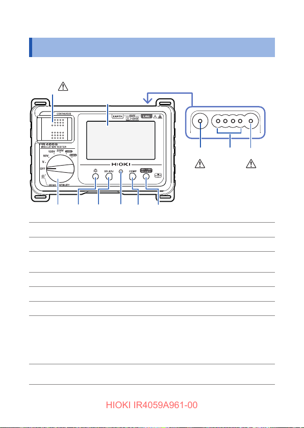
Names and Functions of Parts
HIOKI IR4059A961-00
1.2 Names and Functions of Parts
Front
(p. 24, p. 27, p. 41, p. 47)
Display
Top
MEASURE key (p. 21) Starts insulation resistance measurement.
EARTH terminal Connects the black test lead.
CONTROL terminal
LINE terminal Connects the red test lead.
Rotary switch Selects measurement functions.
LIGHT key
0Ω ADJ key
Live circuit indicator
20
(p. 15)
Controls L9788-10 Test Lead with Remote
Switch (Red)
Turns on and off the backlight.
Performs zero-adjustment for the low
resistance range.(p. 48)
Press with the COMP key simultaneously:
congures the wireless communications
function. (p. 50)
Lights up when voltage remains between
input terminals.
(p. 15)
Page 21
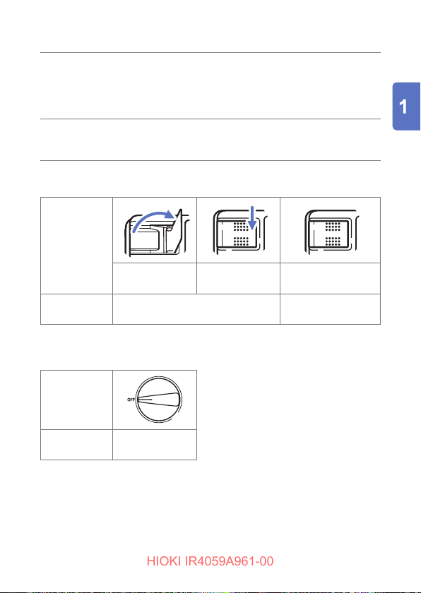
Names and Functions of Parts
HIOKI IR4059A961-00
Sets the comparator’s judgment reference
COMP key
RELEASE key
value.
Press with the 0
congures the wireless communications
function. (p. 50)
Press before measurement to set the instrument
to the 500 V or 1000 V range (to prevent
erroneous application of the test signal).
ADJ key simultaneously:
Ω
MEASURE key
MEASURE key
operation
Pull*
Description in
this manual
*: Convenient way for performing measurement repeatedly
Turn on the MEASURE key.
Press and hold
right side
Power OFF
Rotary switch
status
Fold down
(or release).
Turn off the
MEASURE key.
Description in
this manual
Turn off the rotary
switch.
Rear (Serial number label)
The serial number consists of nine digits. The rst two indicate the year
of manufacture (the last two digits of the Western year), and the next two
indicate the month of manufacture.
21
Page 22
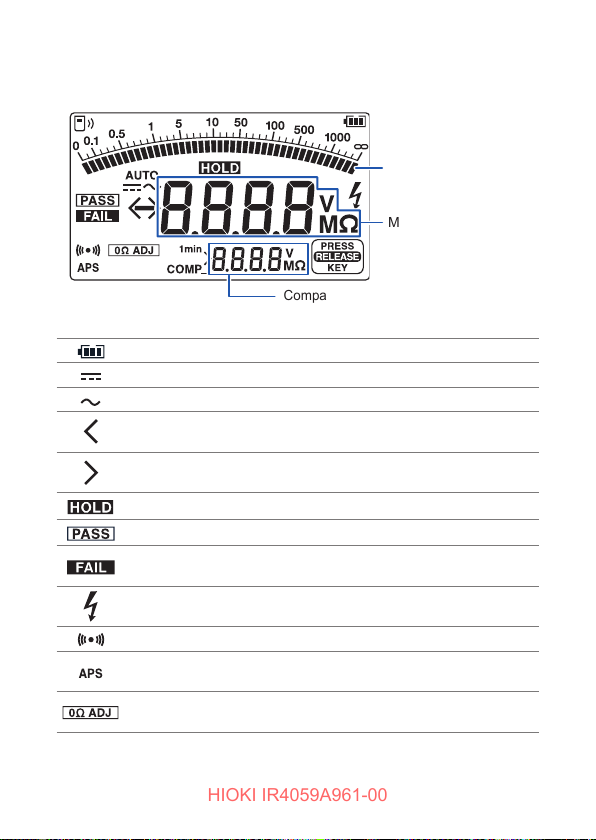
Names and Functions of Parts
HIOKI IR4059A961-00
Display
Battery indicator (three levels) (p. 35)
Turns on when the voltage measured with the V range is DC.
Turns on when the voltage measured with the V range is AC.
Blinks when the measured value is less than the minimum display
value.
Blinks when the measured value is greater than the maximum
display value.
Turns on when the measured value is retained.
Turns on when the comparator judgment is PASS (good). (p. 38)
Turns on when the comparator judgment is FAIL (defective).
(p. 38)
Blinks when a dangerous voltage exists between the
measurement terminals.
Judgment result buzzer (only when comparator is set) (p. 38)
Appears 30 s before auto power save function is activated.
(p. 36)
Turns on when zero adjustment is performed during low
resistance measurement. (p. 48)
Bar graph
Measured value
Comparator judgment reference value or
1-minute value
22
Page 23
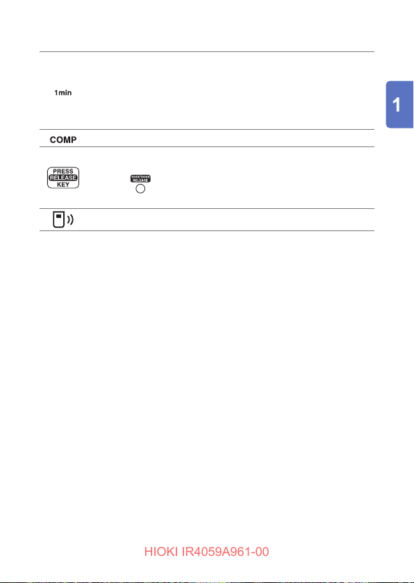
Names and Functions of Parts
HIOKI IR4059A961-00
Displaying 1-minute values (p. 44)
• Turns on when 1 minute has passed since the start of insulation
resistance measurement.
• Indicates that the resistance value on the bottom of the display
is a 1-minute value (the measured value 1 minute after the start
of measurement).
Turns on when the comparator function is enabled. (p. 38)
Turns on when the instrument is set to the 500 V range or the
1000 V range.
Pressing
measurement.
Indicates wireless communications function status. (p. 50)
turns off the indicator and enables insulation
23
Page 24
Names and Functions of Parts
HIOKI IR4059A961-00
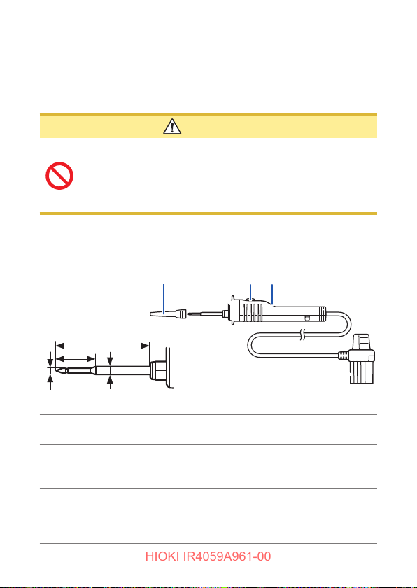
L9788-11 Test Lead Set with Remote Switch
Model L9788-11 is a set of Model L9788-10 Test Lead with Remote Switch
(red) and a test lead (black).
See “Options” (p. 7)
CAUTION
The MEASURE key of the instrument is enabled even
when the L9788-10 is connected to an insulation
resistance tester. Note that the testing voltage is output
when the MEASURE key of the instrument is turned ON
while the L9788-10 is connected.
Refer to “Attaching the L9788-92 Breaker Pin” (p. 32)
L9788-10 Test Lead with Remote Switch (optional)
Sleeve
Enlarged tip view
35
16
Plug
1.8
φ
Light
3.0
φ
MEASURE key
Judgment display
24
Unit: mm
Lights up interlocked with the backlight of the
instrument.
• Starts insulation resistance measurement.
• Lights up in red interlocked with the live wire
warning indicator of the instrument.
Lights up in accordance with the comparator
judgment result.
• PASS: Green
• FAIL: Red
Page 25
Preparing for Measurement
HIOKI IR4059A961-00
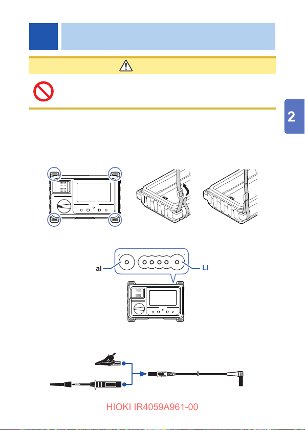
2
CAUTION
Attach the strap securely to the ttings on the instrument.
If insecurely attached, the instrument may fall and be
damaged when carrying.
Insert the batteries. (p. 27)
1
Attach the strap.
2
Pass the strap through a lug-hole on the instrument.
Secure the strap at 4 positions.
Connect the test leads to the terminals.
3
EARTH terminal
Connect the black
test lead.
Attach each test pin or alligator clip to a lead.
4
LINE terminal
Connect the red
test lead.
Fully insert the test lead to the
test pin or alligator clip.
or
25
Page 26
Protector
HIOKI IR4059A961-00
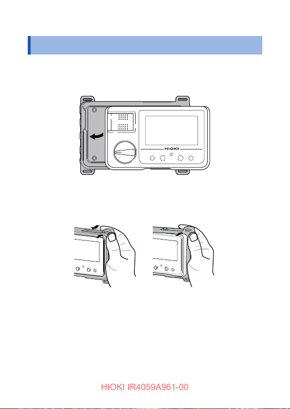
2.1 Protector
Attaching the protector
Tilt the instrument and slide it into the protector, and then push the
entire instrument into the protector.
Removing the protector
Hold it with both hands and push the one end of the protector down.
26
Page 27
Replacing Batteries or Fuse
HIOKI IR4059A961-00
2.2 Replacing Batteries or Fuse
Before using the instrument for the st time, insert four LR6 Alkaline
batteries or four fully charged HR6 Nickel-metal hydride batteries.
WARNING
• To avoid electric shock, turn off the MEASURE key,
disconnect the test leads from the measuring object
before replacing the battery cover.
• After replacing the batteries, reattach the cover and
secure the screw before using the instrument.
• Battery may explode if mistreated. Do not
shortcircuit, recharge, disassemble or dispose of in
re.
• Replace the fuse only with one of the specied type,
characteristics, rated current, and rated voltage. Do
not use fuses other than those specied (especially,
do not use a fuse with higher-rated current) or do
not short circuit and use the fuse holder. Doing so
may damage the instrument and result in bodily
injury.
Fuse type: FF0.5 AH/1000 V (70 172 40.0.500:
SIBA GmbH) (Fast blow, arc-extinguishing material
included, and high breaking capacity)
The fuses can be purchased via authorized Hioki
distributor or reseller.
• To prevent instrument damage or electric shock,
use only the screw for securing the battery cover
in place that are originally installed. If you have lost
a screw or nd that a screw is damaged, please
contact your authorized Hioki distributor or reseller.
27
Page 28
Replacing Batteries or Fuse
HIOKI IR4059A961-00
CAUTION
Poor performance or damage from battery leakage could
result. Observe the cautions listed below.
• Do not mix old and new batteries, or different types of
batteries.
• Pay attention to the polarity markings “+” and “−”, so
that you do not insert the batteries the wrong way
around.
• Do not use batteries after their recommended expiry date.
• Do not leave depleted batteries inside the instrument.
• Replace batteries only with the specied type.
• Use batteries with low internal resistance.
• The battery indicator blinks when the remaining battery capacity
is low. In this case, measurement is not possible. Replace the
batteries with new ones. (p. 35)
• Handle and dispose of batteries in accordance with local
regulations.
Nickel-metal hydride batteries
CAUTION
When using the instrument, insert four LR6 Alkaline
batteries or four fully charged HR6 Nickel-metal hydride
batteries.
The instrument powered by nickel-metal batteries will indicate an
inaccurate remaining-battery level; however, it can be used without
any trouble even with such batteries inserted.
See the continuous operating time below.
Continuous operating time when LR6 Alkaline batteries are used
(reference values at 23°C)
• Approx. 20 hours (without the Z3210 installed, with the
comparator and backlight set to off, when making measurement
using the 500 V range with the measurement terminals open-
28
Page 29

Replacing Batteries or Fuse
HIOKI IR4059A961-00
circuited)
• Approx. 15 hours (with the Z3210 installed, in wireless
communication, with the comparator and backlight set to off,
when making measurement using the 500 V range with the
measurement terminals open-circuited)
Continuous operating time when HR6 Nickel-metal hydride batteries
are used (reference values at 23°C) (when using 1900 mAh nickelmetal hydride batteries).
• Approx. 31 hours (without the Z3210 installed, with the
comparator and backlight set to off, when making measurement
using the 500 V range with the measurement terminals opencircuited)
• Approx. 28 hours (with the Z3210 installed, in wireless
communication, with the comparator and backlight set to off,
when making measurement using the 500 V range with the
measurement terminals open-circuited)
Visit an FAQ page on Hioki’s global website for more information
about nickel-metal hydride batteries that Hioki has guaranteed to
work.
The instrument with nickel-metal hydride batteries inserted is not
drop-proof.
29
Page 30
Replacing Batteries or Fuse
HIOKI IR4059A961-00
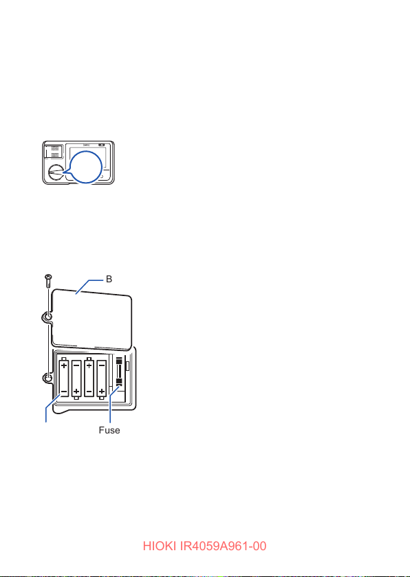
Procedure
You will need:
• LR6 Alkaline battery ×4 or
HR6 Nickel-metal hydride battery ×4
• Phillips-head screwdriver (No. 2)
OFF
Turn off the rotary switch and
1
remove the test lead from the
instrument.
Remove the protector. (p. 26)
2
Rear
Battery cover
Batteries
Check the
polarity.
Fuse
FF0.5 AH/1000 V
(70 172 40.0.500:
SIBA GmbH)
30
Loosen the fastening screw
3
and remove the battery cover.
Replace all four batteries or
4
the fuse.
Attach the protector. (p. 26)
5
Slide the battery cover back
6
into place and tighten the
screw.
Page 31
Using the L9788-10 Test Lead with Remote Switch (Red)
HIOKI IR4059A961-00
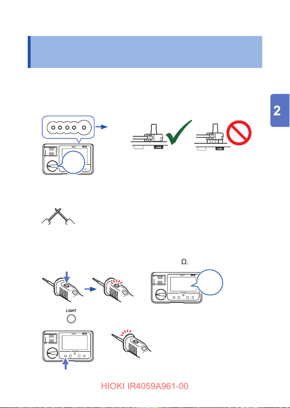
2.3 Using the L9788-10 Test Lead with Remote Switch (Red)
Pre-measurement inspection
Turn off the rotary
1
switch.
Fully insert the L9788-10 plug
2
into the LINE terminal of the
instrument.
OFF
With the test lead tips shorted, press the MEASURE key on
4
the L9788-10.
Check the following:
5
• The L9788-10’s MEASURE key lights up red in conjunction with the
live circuit indicator on the instrument.
• The indicator of the instrument indicates 0 M
6
Press .
OK
Set the rotary switch to insulation
3
resistance range.
.
Ω
0 M
Ω
Check that the L9788-10 tip lamp
lights up.
NO
31
Page 32
Using the L9788-10 Test Lead with Remote Switch (Red)
HIOKI IR4059A961-00
Replacing the Tip Pin (optional) for the L9788-10
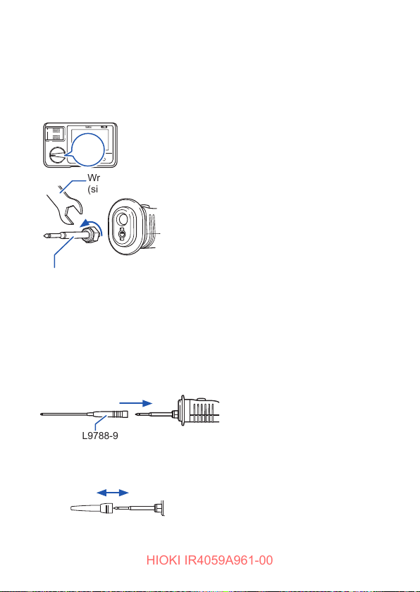
When the tip pin of the L9788-10 Test Lead with Remote Switch
(Red) (option) is worn out or broken, it can be replaced. The tip pin
can be purchased via authorized Hioki distributor or reseller.
Turn off the rotary switch and
1
OFF
disconnect the L9788-10.
Wrench
(size: 7 mm width)
L9788-90 Tip Pin
Remove the tip pin by rotating
2
with a wrench.
Attach the new tip pin to the
3
L9788-10 by rotating with a
wrench.
(Tightening torque: 0.3 Nm)
Check the operation.
4
Measure a measuring object of known
values and use after checking that the
resistance is correct.
Attaching the L9788-92 Breaker Pin
Remove the sleeve of the L9788-10 and attach the breaker pin.
Fully insert.
L9788-92 Breaker Pin
Removing and attaching the test lead sleeves
Safely store the removed sleeves so as
not to lose them. (p. 18)
32
Page 33
Installing the Z3210 Wireless Adapter
HIOKI IR4059A961-00
Removing the sleeves Attaching the sleeves
Hold the bottom of the sleeves
and pull the sleeves off. (For
safety reasons, the cap has been
manufactured to t snugly so that
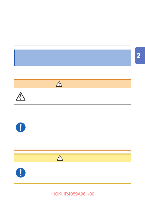
it cannot be easily removed.)
Insert the metal pins of the test leads into
the holes of the sleeves, and rmly push
them all the way in.
2.4 Installing the Z3210 Wireless Adapter
The wireless communications function can be used by installing the Z3210
Wireless Adapter (option) to the instrument.
WARNING
• To avoid electric shock, turn off the MEASURE
key and remove the test leads from the measuring
object before removing the battery cover.
• After installing or removing the Z3210, be sure to
reattach the battery cover and secure it in place
with the screw before using the instrument.
• To prevent instrument damage or an electric shock,
use only the screws that are originally installed for
securing the battery cover in place. If you have lost
any screws or nd that any screws are damaged,
please contact your authorized Hioki distributor or
reseller.
After touching any metallic part, such as a doorknob,
to eliminate static electricity from your body, connect or
disconnect the Z3210. Failure to do so could cause static
electricity to damage the Z3210.
CAUTION
33
Page 34
Installing the Z3210 Wireless Adapter
HIOKI IR4059A961-00
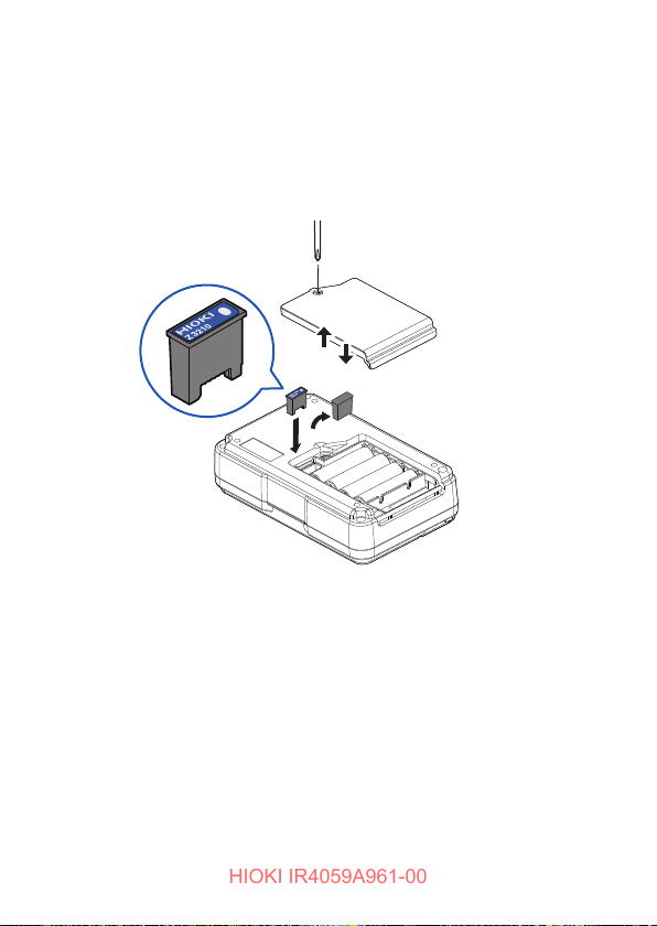
Procedure
You will need:
• Phillips-head screwdriver (No. 2)
• Flat-head screwdriver
• Z3210 Wireless Adapter (option)
Rear
Turn off the rotary switch and remove the test leads.
1
Remove the protector. (p. 26)
2
Unscrew the screws and remove the battery cover.
3
Remove the protective cap with a at-head screwdriver.
4
Exercising care to orient the Z3210 correctly, install the
5
Z3210 as far as it will go.
Reattach the battery cover and tighten the screws.
6
Attach the protector. (p. 26)
7
34
Page 35
Measurement
HIOKI IR4059A961-00
3
3.1 Pre-measurement Inspection
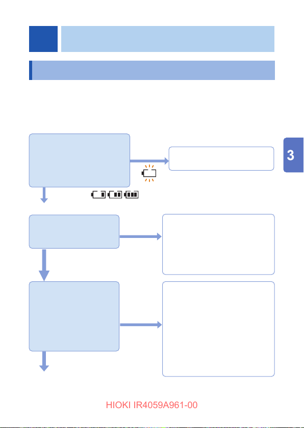
Before using the instrument, verify that it operates normally to ensure that no
damage occurred during storage or shipping. If you nd any damage, contact
your authorized Hioki distributor or reseller.
Checking the remaining battery charge
Is the battery level adequate?
Set the rotary switch away
from OFF and conrm the
battery indicator.
Turns on
Checking the test lead
Is the white portion
(insulation layer) inside
the cable exposed?
Not Exposed
Blinks
Exposed
Replace with the new batteries.
(p. 27)
Do not use and replace with
those specied by Hioki if
damage is present as you could
receive an electric shock.
1. Set the rotary switch to
insulation resistance
range.
2. Short the test lead tips.
3. Is 0 M
displayed when
Ω
the MEASURE key is
turned on?
Displayed
Not
displayed
Inspection complete
Please read the “Operating Precautions” (p. 15) before use.
The following issues may be
occurring:
• The test lead has not been
inserted all the way.
Insert the test lead all the way in.
→
• There is a broken connection in
the test lead.
→ Replace them with those
specified by Hioki.
35
Page 36
Auto Power Save (Power-Saving Function)
HIOKI IR4059A961-00
3.2 Auto Power Save (Power-Saving Function)
When the rotary switch is not in the OFF position, the instrument changes to
the auto power save state approx. 10 minutes after the last operation or live
wire warning indication.
To avoid battery depletion, turn off the rotary switch after use (the auto power
save consumes a small amount of current).
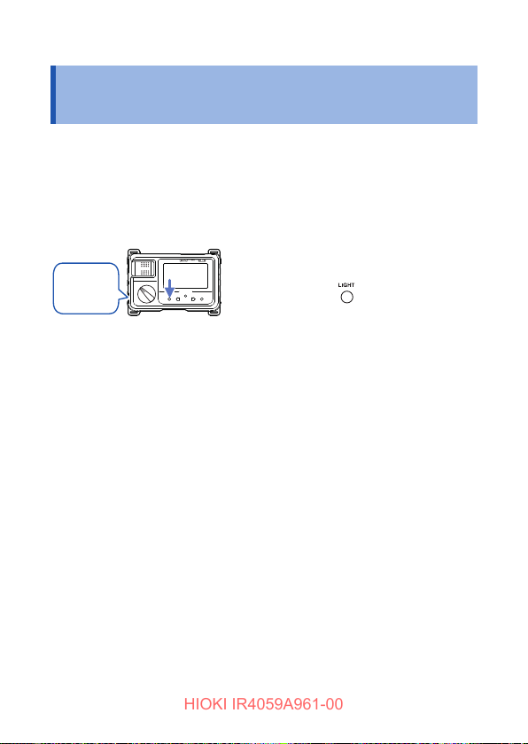
Canceling the auto power save
Other than
the OFF
position
.
Turn on the instrument while
holding down
Recovering from auto power save state
Set the rotary switch to OFF and then return it to its original
position.
36
.
Page 37
Auto Backlight-off (Automatic Light-off Function)
HIOKI IR4059A961-00
3.3 Auto Backlight-off (Automatic Light-off Function)
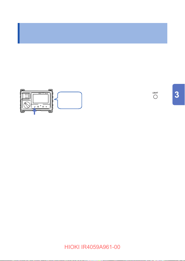
The backlight of the instrument will automatically turn off after approx.
3 minutes has passed since the last operation.
The automatic light-off function can be canceled when working continuously
in a dark location.
Canceling the automatic light-off function
Backlight: OFF
Continuous
short beep
Press for approx. 2 seconds.
Set the rotary switch to any
position other than OFF.
With the backlight off, press
for approx. 2 seconds until the
instrument beeps.
The automatic light-off function is enabled
setting the rotary switch to OFF.
by
37
Page 38
Comparator Function
HIOKI IR4059A961-00
3.4 Comparator Function
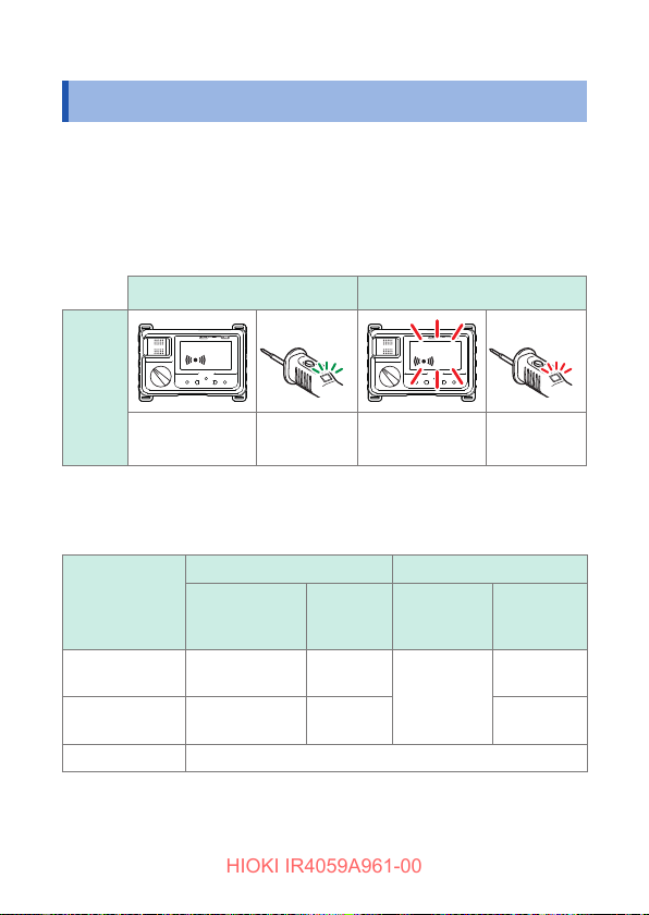
This function compares the measured value with the preset value and judges
whether the result is PASS (good) or FAIL (defective).
Comparator settings for each range will be saved, even if the rotary switch is
turned off.
See the table on the next page for criteria that can be set.
Indication lights up
PASS (good) judgment FAIL (defective) judgment
LED
display
Backlight:
No change
* When using the L9788-10 Test Lead with Remote Switch (Red)
Type of measurements that can be judged
Function
Insulation
Resistance
Low resistance
Voltage Comparator cannot be set.
Lights up in
green*
PASS judgment FAIL judgment
State of
measured
value
Criterion or
higher
Criterion or
lower
Backlight: Lights
up in red
Buzzer Backlight Buzzer
Short beep
Long beep Short beep
Lights up in
red
Lights up in
red*
Long beep
38
Page 39
Setting the Comparator
HIOKI IR4059A961-00
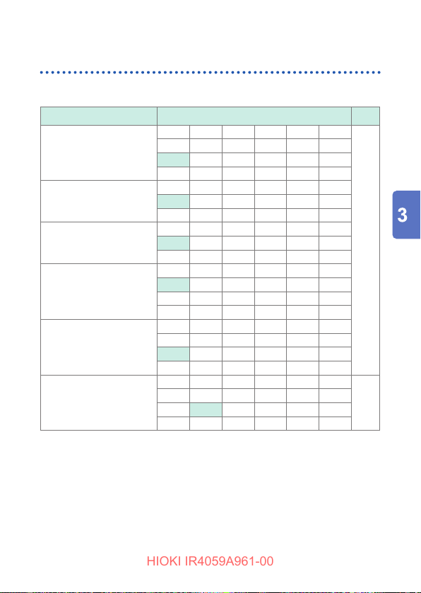
Select a judgment reference from the table below.
1
Range Reference value Unit
0.01 0.02 0.03 0.04 0.05 ‒
50 V
125 V
250 V
500 V
1000 V
Ω
*1: Factory default setting
0.1 0.2 0.3 0.4 0.5 ‒
1
2 3 4 5 ‒
1*
10 ‒ ‒ ‒ ‒ Off
0.1 0.2 0.3 0.4 0.5 ‒
1
2 3 4 5 ‒
1*
10 20 ‒ ‒ ‒ Off
0.1 0.2 0.3 0.4 0.5 ‒
1
2 3 4 5 ‒
1*
10 20 30 40 50 Off
0.1 0.2 0.3 0.4 0.5 ‒
1
2 3 4 5 ‒
1*
10 20 30 40 50 ‒
100 ‒ ‒ ‒ ‒ Off
0.1 0.2 0.3 0.4 0.5 ‒
1 2 3 4 5 ‒
1
20 30 40 50 ‒
10*
100 200 300 400 500 Off
0.1 0.2 0.3 0.4 0.5 0.6
1 2 3 4 5 6
1
10 20*
30 40 50 60
100 200 ‒ ‒ ‒ Off
Comparator Function
M
Ω
Ω
39
Page 40
Comparator Function
HIOKI IR4059A961-00
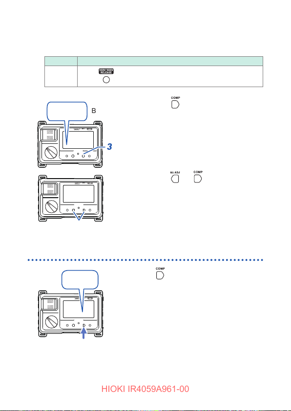
Set the rotary switch to the range for which you wish to set
2
the judgement reference.
Range Operation
500 V
1000 V
COMP
Press
to release the lock.
Blinks
Press .
3
[COMP] blinks and the resistance
value that will be used as the
judgement reference is displayed.
Press or to select the
4
judgement reference. (p. 39)
If there is no operation for about
2 seconds after you select the
judgment reference, the comparator
will be set, and [COMP] will light up.
Canceling the Comparator
oFF
40
Press several times to select
[oFF].
If there is no operation for for about 2
seconds after you select, [COMP] will go
off, and the comparator function will be
canceled.
Page 41
Insulation Resistance Measurement
HIOKI IR4059A961-00
3.5 Insulation Resistance Measurement
The instrument is used to measure the insulation resistance to
determine the insulation performance of circuits and equipment.
Before starting a measurement, the voltage to be applied to the
measuring object needs to be selected.
WARNING
Observe the following to avoid electric shock, short
circuit, or damage to the instrument.
• Do not attempt to measure insulation resistance
on a live conductor. Doing so could damage the
instrument or cause an accident that might result
in injury or death. Always turn off power to the
measuring object before starting.
• When measuring insulation resistance, dangerous
voltage is applied to the measurement terminals. To
avoid electric shock, do not touch the metal part of
the test leads.
• Do not touch the measuring object immediately after
measurement. Doing so may cause electric shock
due to a highly charged voltage.
• Discharge the measuring object with the discharge
function of the instrument after a measurement. (p. 46)
• Insulation resistance is the ratio of applied voltage to leakage current.
Displayed value may not stabilize depending on the measuring object,
but it is not a failure of the instrument.
• Press the MEASURE key fully down until a live circuit indicator lights
up. If the button is not pressed down fully, a proper measurement cannot
be made.
• Turn off the rotary switch after use.
• Disconnection when measuring is recommended of any equipment
having a lower withstanding voltage than the test voltage, or equipment
or parts having an unknown withstanding voltage connected to the circuit
to be measured.
41
Page 42
Insulation Resistance Measurement
HIOKI IR4059A961-00
Lock Function
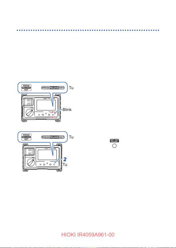
This function is used to avoid applying high voltage such as 500 V
or 1000 V to equipment having a lower withstanding voltage. This
function will prevent the test voltage from being output even if the
MEASURE key is pressed while the rotary switch is set to the 500
or 1000 V range.
Releasing the lock
V
or
or
Turns on
Blinks
Turns off
Turns off
Set the rotary switch to the
1
500 V or 1000 V range.
Press .
2
Pressing this key unlocks the
instrument and switches to the
measurement screen.
The screen is locked 1 minute after the last measurement or operation
again.
42
Page 43
Insulation Resistance Measurement
HIOKI IR4059A961-00
Measuring Insulation Resistance
CAUTION
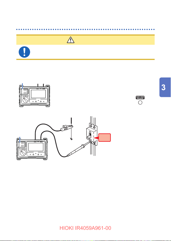
To avoid electric shock, turn off the measuring line
breaker.
Example: When measuring the insulation resistance between the circuit
5
7
3
4
5
and the ground
Turn off the MEASURE key.
OFF
1
ON
OFF
6
Connect the black test lead to the ground side of the
object being measured.
Connect the red test lead to the measuring object.
If there is any remaining voltage on the measuring object, red and white
blink alternately on the backlight.
Press and hold the MEASURE key.
To make continuous measurements, pull up the MEASURE key. (p. 21)
Do not touch the metal part (tip), on which a dangerous voltage is
present during measurement, of the test lead.
1
Set the rotary switch to a test voltage
2
of 50 V to 1000 V.
In the 500 V or 1000 V range, press to
release the lock. (p. 42)
3
Source (primary side)
OFF
4
Load (secondary side)
43
Page 44
Insulation Resistance Measurement
HIOKI IR4059A961-00
Check the value after the indicator has stabilized.
6
Turn off the MEASURE key with the test leads connected
7
to the measuring object.
The last measured values and are displayed and starts
discharging. (p. 46)
• Do not switch the function to other function or rated voltage when the
measurement is in progress.
• The instrument will return to the locked state when about 1 minute of no
operation elapses during measurement in the 500 V and 1000 V ranges. To
continue measurement, release the lock. (p. 42)
Displaying 1-minute Values
The function cannot be used if the comparator function has been
enabled. Disable the comparator function before use. (p. 40)
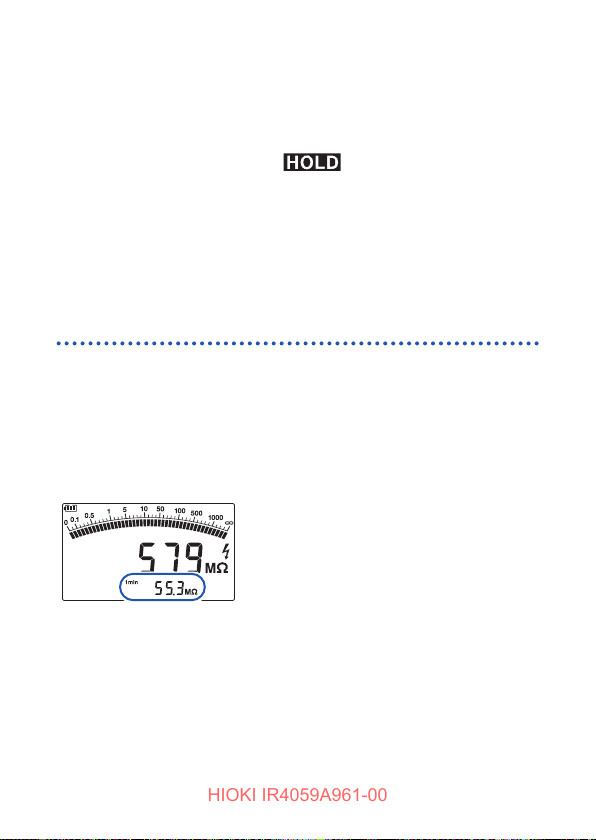
This function automatically retains the measured value (1-minute
value) 1 minute after the start of measurement (after the MEASURE
key is turned on). Use this function when measuring a object such
as a cable that includes a capacitance component.
• No value is shown if less than 1 minute has
elapsed since the start of measurement.
Retained measured value
44
Page 45
Insulation Resistance Measurement
HIOKI IR4059A961-00
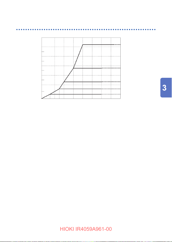
Voltage Characteristics of Measurement Terminals
1200
1000
800
600
400
200
Voltage generated [V]
100
0
0.05 0 .125
0 0.1 0.25 0.5 1 10 100 1000
Resistance of measuring object [MΩ]
Rated 1000 V
Rated 500
Rated 250
Rated 125
V
Rated 50
∞
V
V
V
45
Page 46
Discharging Function
HIOKI IR4059A961-00
3.6 Discharging Function
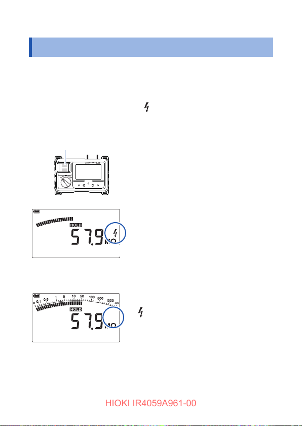
After measurements are completed, discharge the measuring object.
When objects with capacitance component are measured, a charge
equivalent to the rated measurement voltage remains in the object
that may cause electric shock.
When measuring a solar panel,
the instrument will continue to detect the panel’s voltage once
discharging ends.
OFF
Turned on
Discharging
mark may not disappear since
Without removing the test leads
from the measuring object, turn off
the MEASURE key.
The built-in discharge resistor
automatically discharges the item.
The bar graph level decreases according
to discharge. However, measuring objects
with smaller capacitance component
discharge quickly and the bar graph level
may not change.
When the discharge is completed,
mark is turned off.
Discharged
46
Off
The time required for discharge depends
on the capacitance value.
Page 47
Voltage Measurement
HIOKI IR4059A961-00
3.7 Voltage Measurement
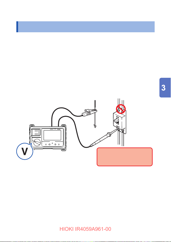
This instrument can measure the AC voltage and DC voltage of
commercial power. The instrument can check to ensure that the
measuring object is not live before measuring insulation resistance.
• During measuring, do not switchover to other functions.
• For waveforms other than sine waves, some errors may occur.
• Displayed values can frequently uctuate due to induction
potential even when no voltage is applied. This, however, is not a
malfunction.
Example: When measuring the voltage between the circuit and ground
Source
(primary side)
3
Load
(secondary side)
4
1
Set the rotary switch to V.
1
Earth
2
Line
Always connect the test lead
to the secondary side of the
breaker.
Connect the black test lead to the earth side of the object
2
being measured.
Connect the red test lead to the line side of the breaker.
3
Check the value after the indicator has stabilized.
4
47
Page 48
Low Resistance Measurement
HIOKI IR4059A961-00
3.8 Low Resistance Measurement
WARNING
Do not measure under a live circuit condition.
CAUTION
• If active circuits are connected to the measuring object
circuit in parallel, the impedance and transient current of
the parallel circuit could cause measurement errors.
• Auto range selection may not operate in a stable
manner depending on the measuring object (for
example, a motor, transformer, or coil).
• The instrument may not be able to obtain an accurate
measured value if there is a capacitance component in
parallel with the measuring object.
The comparator function can be used during low resistance
measurement. See “3.4 Comparator Function” (p. 38)
For accurate measurements, be sure to perform zero adjustment
before measuring, to cancel the wire resistance of the test leads.
Zero adjustment can be performed with readings of up to a
maximum of 3
[Err 0ΩADJ] will be displayed, and zero adjustment will not be
possible. Wire the instrument so that the wiring resistance is 3
less.
In the following circumstances, repeat the zero adjustment procedure:
• After changing test leads
• When the ambient temperature changes by 1°C or more
• After replacing the fuse
. When the reading exceeds 3
Ω
, [Err 1] or
Ω
or
Ω
48
Page 49
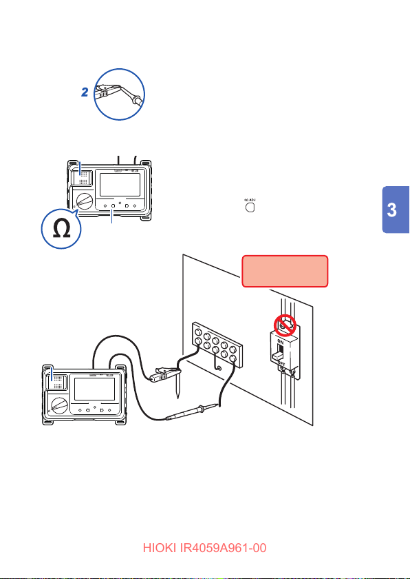
Low Resistance Measurement
HIOKI IR4059A961-00
Example: Checking continuity of grounding wire
2
ON
3
OFF
4
1
Set the rotary switch to the Ω.
1
Short circuit the tip of the test
2
lead.
Turn on the MEASURE key.
3
Turn off the MEASURE key to
4
retain the measured value.
Press .
5
5
Do not measure
live wires.
ON
7
OFF
8
6
6
Connect the test lead to the measuring object.
6
Press and hold the MEASURE key to check the displayed
7
value.
To make continuous measurements, pull up the MEASURE key.
Turn off the MEASURE key after measurement.
8
49
Page 50
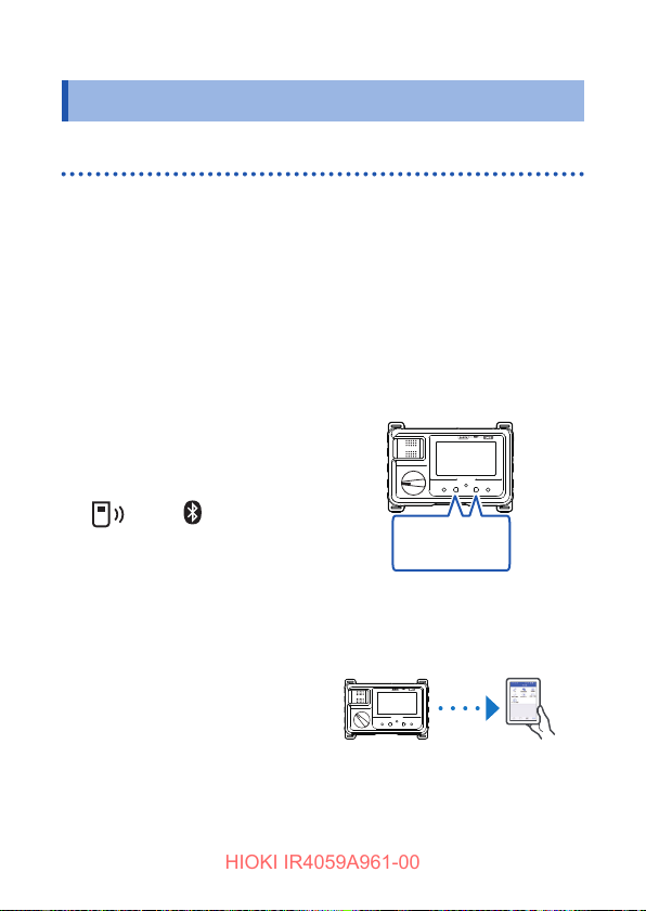
Wireless Communications Function
HIOKI IR4059A961-00
3.9 Wireless Communications Function
Using the GENNECT Cross
This function cannot be used at the same time as the HID function.
(p. 54)
When the wireless communications function is enabled, you can
review measurement data and create measurement reports on
mobile devices. For details, see the Help function in the GENNECT
Cross (application software, free of charge).
Install the Z3210 Wireless Adapter (option) to the
1
instrument. (p. 33)
Install the GENNECT Cross on your mobile device.
2
Turn on the instrument
3
to enable the wireless
communications function.
mark or mark
On: Enabled
Off: Disabled
Blinks: Communicating
Launch the GENNECT Cross and pair it with the instrument.
4
(p. 51)
Select the standard
5
measurement function and
start measurement.
• The communication distance is approx. 10 m (line of sight). The
distance over which data can be sent and received varies greatly
depending on whether there are any obstructions between the
paired instruments (for example, walls, metal barriers, etc.) and
50
0Ω ADJ key
+
COMP key
Press and hold the two keys
for at least 1 s.
Page 51

Wireless Communications Function
HIOKI IR4059A961-00
on the distance between the instrument and the oor (or ground).
To ensure stable communication, verify adequate signal strength.
• Although the GENNECT Cross is provided free of charge,
downloading or using the application software may incur Internet
connection charges. Such charges are the sole responsibility of
the user.
• The GENNECT Cross is not guaranteed to operate on all mobile
devices.
• The Z3210 uses 2.4 GHz band wireless technology. It may not be
possible for the device to establish a wireless connection when
used in the vicinity of other devices that use the same frequency
band, for example Wi-Fi devices (IEEE 802.11.b/g/n).
51
Page 52
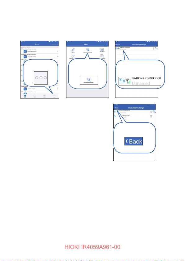
Wireless Communications Function
HIOKI IR4059A961-00
Pairing the App
Home>Other
Instrument
Settings
• When the app is launched for the rst
time (before being paired with any
instrument), the connection setup
screen will be displayed.
• While the mobile device is displaying
the connection setup screen, simply
move it close to the the instrument to
automatically pair it with the instrument
(the app can be paired with up to 8
instruments).
• Allow about 5 to 30 seconds for the
instrument to pair with the app after
being turned on. If the instrument
fails to pair within 1 minute, relaunch
GENNECT Cross and cycle the
instrument’s power.
• Instruments that have been registered
do not require to be registered again.
The instrument is
automatically registered.
Returns to the
screen.
Home
52
Page 53
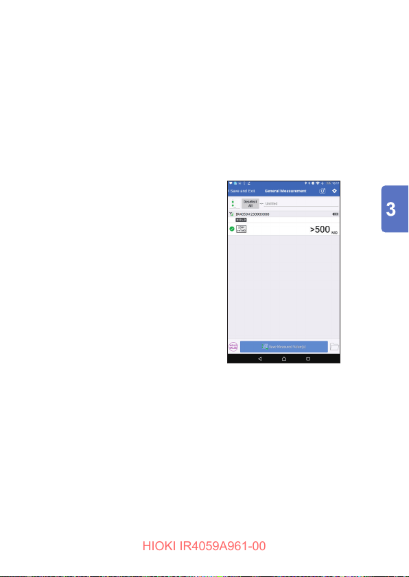
Wireless Communications Function
HIOKI IR4059A961-00
Making Measurements with the Wireless
Communications Function
On the home screen, select the standard measurement function from
the options, standard measurement, logging and waveform display, to
start a measurement. For more information about each function, see
the help function in the GENNECT Cross.
The values displayed by the instrument may be different from the
values displayed by the application software due to communication
delays or differences in the update timing.
Standard measurement
Measured values of multiple channels
are saved.
53
Page 54
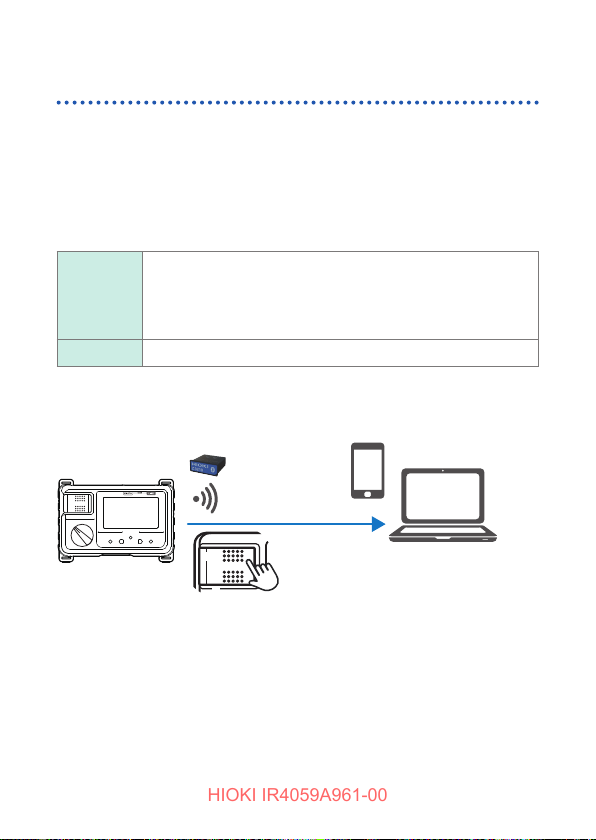
Wireless Communications Function
HIOKI IR4059A961-00
Excel Direct Input Function (HID function)
This function cannot be used at the same time as GENNECT Cross
(p. 50).
The human interface device (HID) prole, with which the Z3210
Wireless Adapter is equipped, is a prole same as that wireless
keyboards use.
HID ON Preparatory to data entry, open an Excel le on
your mobile device or computer and choose a cell.
Freezing the instrument’s display can enter the
measured values on the cells.
HID OFF Select this setting when using GENNECT Cross.
The setting whether the HID function has been enabled or disabled
will not be saved in the instrument but in the Z3210.
Enter measured values.
Measured value input method
Insulation resistance, low resistance:
Press and release the MEASURE key.
Voltage: Press the MEASURE key.
54
Page 55
Wireless Communications Function
HIOKI IR4059A961-00
Checking and changing the HID setting
Set the rotary switch to OFF.
1
Install the Z3210 Wireless Adapter (option) to the
2
instrument.
See “2.4 Installing the Z3210 Wireless Adapter” (p. 33)
If the wireless communications function is off, you won’t be able to check or
change the HID setting. Enable the wireless communications function rst
before attempting to check or change the HID setting (Step 3 on p. 50).
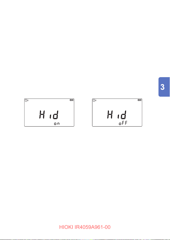
Check the HID setting.
3
Turn on the instrument while holding down the RELEASE key to display
the serial number screen.
Press and hold the RELEASE key for at least 3 s to display the HID
setting saved by the Z3210.
or
To leave the HID setting unchanged
Set the rotary switch to OFF.
To change the HID setting
Proceed to Step 4.
If the instrument beeps and the display doesn’t change
Using GENNECT Cross (Ver. 1.8 or later), update the Z3210 to the latest
version.
Change the HID setting.
4
Toggle the HID setting on and off by pressing the 0
COMP key.
Accept the setting
5
Press the RELEASE key to accept the HID setting. The instrument will
automatically turn off.
ADJ key or the
Ω
55
Page 56
Wireless Communications Function
HIOKI IR4059A961-00
IMPORTANT
To switch from the HID function to GENNECT Cross
If you launch GENNECT Cross without unpairing the mobile phone and
the instrument, the application may fail to recognize the instrument as a
connected device.
Reconnect the instrument to GENNECT Cross as follows:
1. Delete the instrument from your device’s Bluetooth
2. Turn off the Z3210’s HID function. (p. 55)
3. Reconnect the instrument using GENNECT Cross’s connected device
settings.
®
settings.
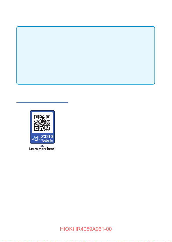
For details, please check the Z3210’s website.
https://z3210.gennect.net
56
Page 57
Specications
HIOKI IR4059A961-00
4
4.1 General Specications
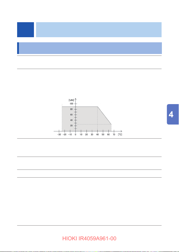
Operating
environment
Operating
temperature
and humidity
Indoors, Pollution Degree 2,
altitude up to 2000 m (6562 ft.)
−25°C to 40°C (−13°F to 104°F),
90% RH or less (no condensation)
40°C to 65°C (104°F to 149°F), at 65°C and below
relative with linear decrease up to 25% RH (no
condensation)
Storage
temperature
and humidity
Dustproof and
waterproof
Drop proof On concrete: 1 m
Standards
*1: Subclause 4.3 of Part 4 (Interchanging of test leads) is not applicable
when model L9788-10 is used.
−25°C to 65°C (−13°F to 149°F),
90% RH or less (no condensation)
IP40 (EN 60529)
EN 61326
EMC:
Safety: EN 61010
EN 61557-1
EN 61557-2
EN 61557-4*
EN 61557-10
1
57
Page 58
General Specications
HIOKI IR4059A961-00
Power supply • LR6 Alkaline battery ×4
Continuous
operating time
When using four
LR6 Alkaline
batteries
(reference value
at 23°C)
Dimensions Approx. 160W × 98H × 46D mm
Mass Approx. 536 g (18.9 oz.)
Product warranty period: 3 years
Fuse
(Replacements)
Accessories See “Verifying Package Contents” (p. 6)
Options See “Options” (p. 7)
Rated supply voltage: 1.5 V DC ×4
• HR6 Nickel-metal hydride battery ×4
Rated supply voltage: 1.2 V DC ×4
Maximum rated power: 3 VA
Approx. 20 hours (without Z3210 installed, comparator
off, backlight off, measured with measurement terminal
open at 500 V range)
Approx. 15 hours (with Z3210 installed, using wireless
communications, comparator off, backlight off, measured
with measurement terminal open at 500 V range)
(6.3W × 3.86H × 1.81D in.) (excluding protrusions)
(including battery and protector, excluding test lead)
FF0.5 AH/1000 V (70 172 40.0.500: SIBA GmbH)
(Very fast-blow, arc-extinguishing material included, high
breaking capacity)
58
Page 59
Basic and Accuracy Specications
HIOKI IR4059A961-00
4.2 Basic and Accuracy Specications
Measurement item Insulation resistance measurement:
Function settings
A/D conversion
method
Input/output terminals LINE terminal: Connect red test lead.
Maximum rated
voltage to terminal
Maximum rated
voltage to earth
DC voltage supply, current detection
Low resistance measurement:
DC current supply, voltage detection
Voltage measurement:
Automatic DC/AC detection
AC voltage measurement rectication method:
Mean rectication RMS value indication
, OFF, V, 50 V, 125 V, 250 V, 500 V, 1000 V
Ω
method
ΔΣ
Insulation resistance measurement:
Terminal (−) to which current from the
measurement target ows
Terminal (−) to which current from the
measurement target ows
Low resistance measurement:
Current output terminal
Voltage measurement: + terminal
EARTH terminal: Connect black test lead.
Insulation resistance measurement:
Voltage output terminal (+)
Low resistance measurement:
Terminal to which current from the
measurement target ows
Voltage measurement: − terminal
600 V AC/DC (Voltage measurement)
600 V AC/DC (Measurement Category III)
Anticipated Transient Overvoltage: 6000 V
59
Page 60

Basic and Accuracy Specications
HIOKI IR4059A961-00
Rated operational
conditions
Nominal circuit
voltage*
Accuracy guarantee
conditions
Ambient temperature:
See “Operating temperature and humidity” in
“4.1 General Specications” (p. 57)
Relative humidity:
See “Operating temperature and humidity” in
“4.1 General Specications” (p. 57)
Position: Standard position ±90°
External magnetic eld: 400 A/m or less
Battery voltage: Available effective battery voltage
600 V AC/DC max.
*: The nominal circuit voltage refers to the nominal
voltage of an electric distribution circuit that
can be measured by the instrument (based on
EN 61557).
Accuracy guarantee period: 1 year
Accuracy guarantee period after adjustment
made by Hioki: 1 year
Accuracy guarantee temperature and humidity
range: 23°C ±5°C (73°F ±9°F), 90% RH or less
Position: Standard position ±5°
External magnetic eld: None (Earth’s magnetic
eld)
Battery voltage: Available effective battery voltage
60
Page 61
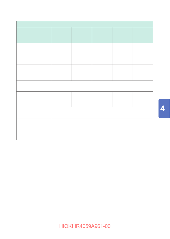
Rated
HIOKI IR4059A961-00
measurement
voltage (DC)
Effective maximum
displayed value
Medium displayed
value
1st effective
measuring
Accuracy
]
[M
Ω
Accuracy
Accuracy
]
Ω
]
Ω
range [M
(Tolerance)
2nd effective
measuring range
(Tolerance)
Other measuring
range [M
(Tolerance)
Basic and Accuracy Specications
Insulation Resistance Measurement
50 V 125 V 250 V 500 V 1000 V
100 M
2 M
0.200 to
10.00
10.1 to
100.0
250 MΩ500 MΩ2000 MΩ4000 M
Ω
5 M
Ω
0.200 to
25.0
25.1 to
250
10 M
Ω
0.200 to
±2% rdg ±2 dgt
50.1 to
±5% rdg
0 to 0.199
±2% rdg ±6 dgt
50.0
500
50 MΩ100 M
Ω
0.200 to
501 to
500
2000
Ω
Ω
0.200 to
1000
1010 to
4000
61
Page 62
Basic and Accuracy Specications
HIOKI IR4059A961-00
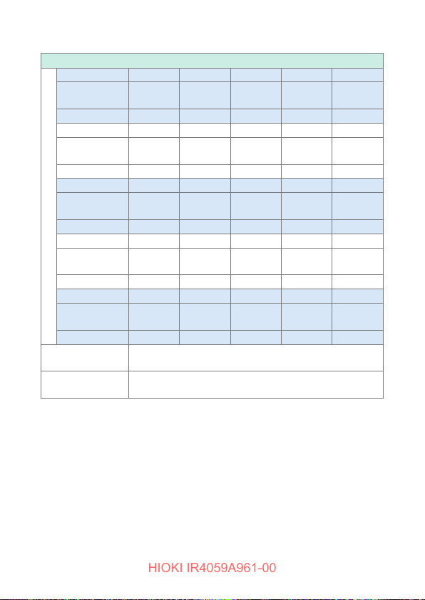
Insulation Resistance Measurement (continued)
Display range 1 M
Maximum
displayed value
Resolution 0.001 MΩ0.001 MΩ0.001 MΩ0.001 MΩ0.001 M
Display range 10 M
Maximum
displayed value
Resolution 0.01 MΩ0.01 MΩ0.01 MΩ0.01 MΩ0.01 M
Display range 100 MΩ100 MΩ100 MΩ100 MΩ100 M
Maximum
displayed value
Resolution 0.1 M
Display range ‒ 250 MΩ500 MΩ1000 MΩ1000 M
Range conguration
Maximum
displayed value
Resolution ‒ 1 M
Display range ‒ ‒ ‒ 2000 MΩ4000 M
Maximum
displayed value
Resolution ‒ ‒ ‒ 10 M
Intrinsic uncertainty
(A)
Operation
uncertainty (B)
1.000 M
10.00 M
100.0 M
1 M
Ω
1.000 MΩ1.000 MΩ1.000 MΩ1.000 M
Ω
10 M
Ω
10.00 MΩ10.00 MΩ10.00 MΩ10.00 M
Ω
100.0 MΩ100.0 MΩ100.0 MΩ100.0 M
Ω
0.1 MΩ0.1 MΩ0.1 MΩ0.1 M
Ω
‒ 250 M
‒ ‒ ‒ 2000 M
±5% rdg (1st effective measuring range)
±12% rdg (1st effective measuring range)
1 M
Ω
10 M
Ω
500 MΩ1000 MΩ1000 M
Ω
1 M
Ω
1 M
Ω
10 M
Ω
1 M
Ω
1 M
Ω
Ω
Ω
Ω
10 M
Ω
Ω
Ω
Ω
Ω
Ω
Ω
Ω
Ω
1 M
Ω
Ω
Ω
4000 M
Ω
Ω
10 M
Ω
Ω
62
Page 63
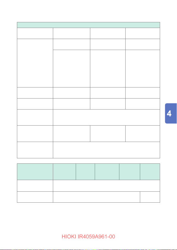
Basic and Accuracy Specications
HIOKI IR4059A961-00
Insulation Resistance Measurement (continued)
Fluctuations caused
by temperature
)*
effects (E
3
Effect of humidity
Effect of magnetic
eld
1st effective
measuring range
±4% rdg
(0°C to 50°C)
±8% rdg
(Greater than or
equal to −25°C and
less than 0°C, or
greater than 50°C
and less than or
equal to 65°C)
±4% rdg and within
allowance
±2.4% rdg ‒ ‒
2nd effective
measuring range
±8% rdg
(0°C to 50°C)
±16% rdg
(Greater than or
equal to −25°C and
less than 0°C, or
greater than 50°C
and less than or
equal to 65°C)
±8% rdg and within
allowance
Other measuring
range
±2% rdg ±6 dgt
(0°C to 50°C)
±4% rdg ±12 dgt
(Greater than or
equal to −25°C
and less than 0°C,
or greater than
50°C and less than
or equal to 65°C)
±2% rdg ±6 dgt
Fluctuations caused
by positioning effect
)
(E
1
Fluctuations caused
by supply voltage
)
effects (E
2
Effects of
capacitance
components
±4% rdg and within
allowance
Within ±10% for capacitance of 5 μF or less (including
variation)
Not applicable
±8% rdg and within
allowance
±2% rdg ±6 dgt
and within
allowance
*: Applicable to the operating temperature range other than 18°C to 28°C.
Rated
measurement
50 V 125 V 250 V 500 V 1000 V
voltage (DC)
Possible number of
measurements
1000 times or more
Overload protection 600 V AC (10 s)
660 V AC
(10 s)
63
Page 64
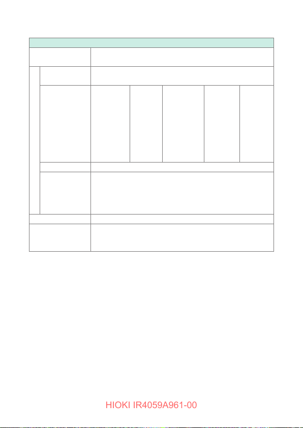
Basic and Accuracy Specications
HIOKI IR4059A961-00
Display update
interval
Open-circuit
voltage
Lower limit
resistance
value to be
maintained rated
measurement
voltage
Rated current 1 mA to 1.2 mA
Short-circuit
current
Measurement terminal voltage characteristic
Response time Within 0.6 s (with resistance load)
Judgment time
Within 0.6 s (no update during response)
1 to 1.2 times of rated measurement voltage
0.05 MΩ0.125 MΩ0.25 MΩ0.5 M
1.2 mA or less
Within 0.3 s
(When switching from an open state to 10 times the default
judgment reference value)
Insulation Resistance Measurement (continued)
1 M
Ω
Ω
64
Page 65
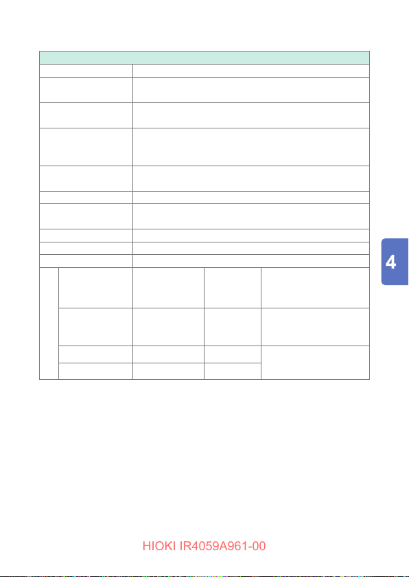
Basic and Accuracy Specications
HIOKI IR4059A961-00
Open-circuit voltage 4.0 V to 6.9 V
Measuring current
Operation uncertainty
(display value before zero adjustment at 6
200 mA or more
±30% rdg (in 0.2 Ω to 2 Ω range)
or less)
Ω
(Calculated based on EN61557)
Low Resistance Measurement
Effect of temperature*
Effect of supply
voltage*
Response time Within 1 s (measurement terminal open → short)
Possible number of
measurements
Overload protection 600 V AC 10 s (by fuse protection)
Zero adjustment range 0
Display update interval Within 1 s
Display range
(Auto range)
10
Ω
100
1000
Ω
Ω
Range conguration
*: Display value is applicable after zero adjustment
(When the temperature changes more than 1°C, zero adjustment is necessary.)
(applied in the operating temperature range excluding
±3% rdg ±2 dgt and within allowance
Maximum
displayed value
10.00
Ω
100.0
Ω
1000
Ω
±3% rdg ±2 dgt
18°C to 28°C)
200 times or more
to 3
Ω
Ω
Resolution Accuracy*
Ω
Ω
±3 dgt (0 Ω to 0.19 Ω)
±3% rdg ±2 dgt
to 10.00 Ω)
(0.20
Ω
±3% rdg ±2 dgt
0.01
0.1
1
Ω
65
Page 66
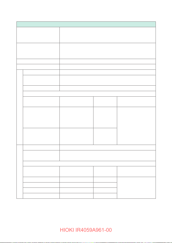
Basic and Accuracy Specications
HIOKI IR4059A961-00
Voltage Measurement
AC/DC automatic
detection range
Effect of temperature
Overload protection 750 V AC (10 s), 750 V DC (10 s)
Display update interval
Input resistance 100 kΩ or more (50 Hz/60 Hz)
Response time
Frequency range 50 Hz/60 Hz
Display range
(Auto range)
420 V
(minimum displayed
value: 30.0 V)
AC Voltage Measurement
600 V 750 V 1 V
AC detected at 30 V or greater (50 Hz/60 Hz).
(pulsating currents with an overlapping AC component of
30 V or more are detected as AC)
Measurement accuracy per 1°C × 0.1
(applied in the operating temperature range excluding
(when input voltage is changed from 0 V to 600 V)
Range conguration
Maximum
displayed value
420.0 V 0.1 V
18°C to 28
°C)
Within 1 s
Within 1.2 s
Resolution Accuracy
±2.3% rdg ±8 dgt
(ranges in excess of
600 V are outside the
accuracy guarantee)
Input resistance 100 kΩ or more
Response time
Display range
(Auto range)
4.2 V 4.200 V 0.001 V
42 V 42.00 V 0.01 V
420 V 420.0 V 0.1 V
DC Voltage Measurement
600 V 750 V 1 V
66
(when input voltage is changed from 0 V to 600 V)
Range conguration
Maximum
displayed value
Within 1.2 s
Resolution Accuracy
±1.3% rdg ±4 dgt
(ranges in excess of
are outside the
600 V
accuracy guarantee)
Page 67
Functionality specications
HIOKI IR4059A961-00
4.3 Functionality specications
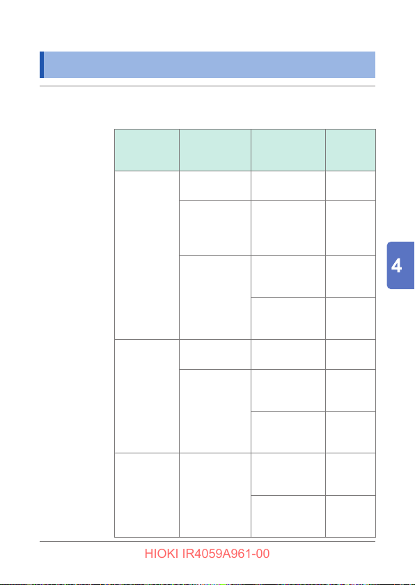
Live circuit
indicator
Turns on when voltage is detected between the LINE
terminal and the EARTH terminal.
Operates with all functions other than OFF.
Function
Insulation
resistance
measurement
Low
resistance
measurement
Voltage
measurement
Status
MEASURE key on– Lights up
MEASURE
key off (during
automatic
discharge)
MEASURE key
off
(except during
automatic
discharge)
MEASURE key on– Lights up
MEASURE key
off
MEASURE key
on or off
Voltage across
terminals
5 V DC or more
30 V AC or more,
+20 V DC or more,
-20 V DC or less
5 V AC or less,
+5 V DC or less,
-5 V DC or more
30 V AC or more,
+5 V DC or more,
-5 V DC or less
1 V AC or less,
+1 V DC or less,
-1 V DC or more
30 V AC or more,
+20 V DC or more,
-20 V DC or less
5 V AC or less,
+5 V DC or less,
-5 V DC or more
Live circuit
indicator
Blinks
Blinks
(Buzzer
sounding)
Turns off
in red
Blinks
(Buzzer
sounding)
Turns off
Blinks
Turns off
67
Page 68
Functionality specications
HIOKI IR4059A961-00
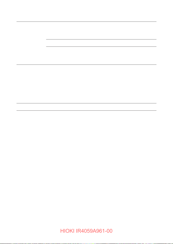
Automatic
electric
discharge
Auto power
save (APS)
Display Semi-transmissive FSTN liquid crystal, positive
Automatically discharges the electric charge still present in
the capacitance of the measuring object after the insulation
resistance measurement.
Bar graph display of residual voltage
• Discharge resistance: 800 k
• Maximum capacitive load: 5 μF
•
Discharge time: Max. 30 s (when connected to 5 μF)
The power will go off automatically approx. 10 minutes after
the last operation or last live circuit indicator display.
• To cancel: Can be canceled using the power supply
activation options.
• Returning from auto power save:
The instrument turns back on when the rotary switch is
temporarily returned to the off position.
or less
Ω
68
Page 69
Functionality specications
HIOKI IR4059A961-00
Bar graph
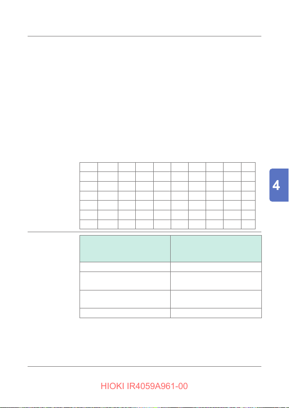
display
Battery
capacity
warning
voltage
Enabled during insulation resistance measurement
• When MEASURE key is on: Insulation resistance value is
displayed.
• During discharge operation following insulation resistance
measurement: Residual voltage is displayed.
• While holding measured value: Insulation resistance
value is displayed.
The resistance value graduation is displayed after rounding
values down to one signicant digit. (For example, if the
display value is 5.99 M
, the bar graph will display a 5 MΩ
Ω
graduation.)
Graduations (unit: M
)
Ω
●: Graduation accompanied by value
0
●
●
●
●
●
●
0.1
1
10
100
1000
0.2 0.3 0.4
2 3 4
20 30 40
200 300 400
2000 3000 4000
0.05
0.6 0.7 0.8 0.9
0.5
●
6 7 8 9
5
●
60 70 80 90
50
●
600 700 800 900
500
●
● ∞
Number of remaining
Battery voltage
battery capacity gauge
marks
5.3 V ±0.19 V or more 3
4.9 V ±0.19 V or more,
less than 5.3 V ±0.19 V
4.5 V ±0.19 V or more,
less than 4.9 V ±0.19 V
2
1
less than 4.5 V ±0.19 V 0 (ashing battery outline)
Hysteresis: The battery capacity gauge will not return to its
previous state until the instrument is turned back on, even if
the battery voltage rises.
Measurement cannot be performed if the capacity gauge
indicates zero. (Measured values will not be displayed.)
69
Page 70
Functionality specications
HIOKI IR4059A961-00
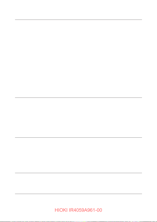
Backlight • Color: white, red
500 V/1000 V
inadvertent
voltage
application
prevention
function
Blown fuse
detection
Firmware
update
function
• Light automatic OFF function: Available (White only. The
instrument will turn off automatically about 3 minutes after
the last operation, or after the last active line warning is
displayed.)
• Turns red when the comparator judgment result is FAIL.
(When the white backlight is active, the white backlight
turns off, and the red backlight turns on.)
• Operation at erroneous input: Alternates white and red in
the following circumstances:
(1) Insulation resistance measurement function: When
a voltage greater than or equal to the voltage that
triggers an active line warning is input
(2) Voltage measurement function: When a voltage that
is greater than or equal to negative or positive full
scale is input
Prevents inadvertent application of voltage to low-voltage
devices when using the 500 V or 1000 V range.
• Unlock method: RELEASE key operation
• When locked: The PRESS RELEASE KEY mark lights up
and the RELEASE key ashes.
• Relock function: After being unlocked, the instrument will
return to the locked state about 1 minute after the last key
operation.
Noties the user if the fuse for protecting the low-resistance
measurement circuit has blown.
• If the user tries to measure a low resistance while
the circuit’s protective fuse has blown, the blown fuse
indicator will ash.
• Low-resistance measurement measured values are not
displayed when the fuse is blown.
The instrument’s rmware can be updated using GENNECT
Cross.
Required: GENNECT Cross (Ver. 1.8 or later)Instrument
rmware (Ver. 2.00 or later)
70
Page 71
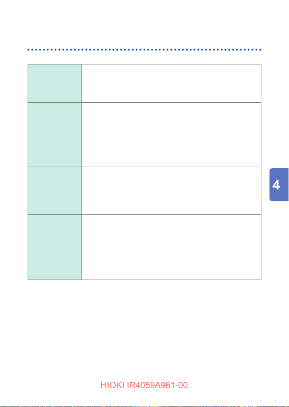
Power-on Options
HIOKI IR4059A961-00
Functionality specications
Canceling the
power-saving
function
(p. 36)
Displaying the
serial number
Checking the
HID setting
(p. 55)
Displaying
the software
version
Turn on the instrument while holding down the LIGHT
key.
Turn on the instrument while holding down the RELEASE
key.
The serial number will be displayed three digits at a time.
In the following example, the month and year of
manufacture are May 2021.
Example: [210] → [512] → [345]
After checking the number, set the rotary switch to OFF.
1. Turn on the instrument while holding down the
RELEASE key.
The serial number screen will be displayed.
2. Press RELEASE key for 3 s or more.
The HID setting saved by the Z3210 will be displayed.
1. Turn on the instrument while holding down the 0
ADJ key and the COMP key.
2. Press the RELEASE key while the [vEr] display is
active.
The display will alternate between the version number
vx.xx
and model
[
]
After checking the number, set the rotary switch to OFF.
4059
[
.
]
Ω
71
Page 72
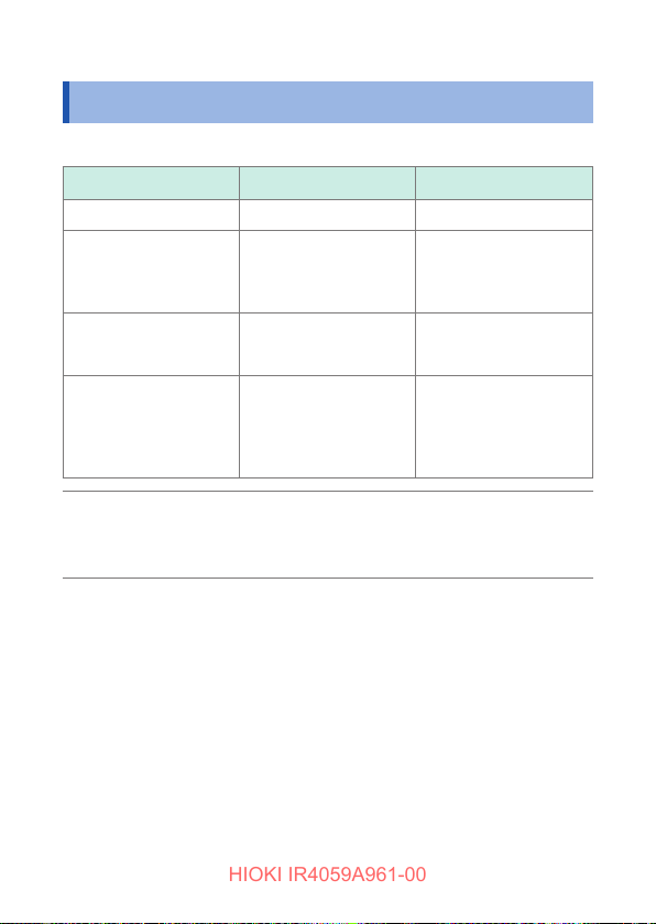
Other Specications
HIOKI IR4059A961-00
4.4 Other Specications
Default condition and setting backup
Item Factory default Setting backup
APS Enabled No
Comparator Enabled
Zero adjustment Disabled Yes
Wireless communication
function settings
For initial values, see
“Setting the Comparator”
(p. 39)
Enabled
When the instrument is
turned on for the rst
time after installing the
Z3210
(on/off, setting value)
(on/off, zero adjustment
value)
Yes (on/off)
Yes
When
operating with
a low supply
voltage
72
The instrument will enter the auto power save state when
the supply voltage falls to 4.0 ±0.3 V or lower, even if auto
power save is set to “off.”
Page 73
Maintenance and Service
HIOKI IR4059A961-00
5
WARNING
Touching any of the high-voltage points inside
the instrument is very dangerous. Customers are
not allowed to modify, disassemble, or repair the
instrument. Doing so may cause re, electric shock,
or injury.
Calibrations
The calibration period varies with the conditions and environment
of use. It is recommended to determine a calibration period based
on those factors and to have the instrument regularly calibrated by
Hioki. Please contact your authorized Hioki distributor or reseller to
have your instrument periodically calibrated.
Precautions when transporting the instrument
When transporting the instrument, be sure to observe the following
precautions:
• To avoid damage to the instrument, remove the batteries from
the instrument. Moreover, be sure to pack in a double carton.
Damage that occurs during transportation is not covered by the
warranty.
• When sending the instrument for repair, be sure to include details
of the problem.
Disposal
Handle and dispose of the instrument in accordance with local
regulations.
73
Page 74

HIOKI IR4059A961-00
Cleaning
• If the instrument becomes dirty, wipe the instrument clean with a
soft cloth slightly moistened with water or a neutral detergent.
IMPORTANT
Never use solvents such as benzene, alcohol, acetone, ether,
ketones, thinners or gasoline. Doing so could deform and
discolor the instrument.
• Wipe the display gently with a soft, dry cloth.
• Wipe the dust from metal parts of alligator clips with a soft cloth to
avoid any impact on the measurements.
74
Page 75
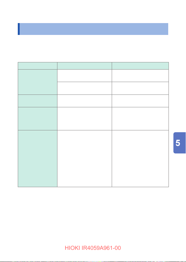
Troubleshooting
HIOKI IR4059A961-00
5.1 Troubleshooting
Before Returning for Repair
If damage is suspected, check the following before contacting your
authorized Hioki distributor or reseller.
Symptom Check Items Remedy and Reference
The power is not
turning on.
The batteries run
out immediately.
The MEASURE
key is not working
for the lead with a
switch.
During insulation
resistance or low
resistance, the live
circuit indicator and
the display blinks in
red, and the buzzer
sounds.
Does the battery have
sufcient charge?
Have the batteries been
installed improperly?
Are you using alkaline
batteries?
Is the plug of the lead with
a switch fully inserted?
Does the voltage applied
between the measurement
terminals exceed the
following values?
Insulation resistance:
approx. 20 V
Low resistance: approx. 5 V
Replace with the new
batteries. (p. 27)
Install the batteries in the
proper orientation.(p. 27)
Replace the batteries with
alkaline batteries.(p. 27)
Fully insert the plug to the
limit without any gaps.
(p. 31)
Make sure that the
measuring object is
disconnected from a live
circuit. If voltage exists in
the measuring object, the
live circuit indicator* blinks.
* The live circuit indicator
may be blink even when
an induction potential is
generated.
75
Page 76
Troubleshooting
HIOKI IR4059A961-00
Symptom Check Items Remedy and Reference
Unable to perform
measurement.
Unable to perform
measurement in
500 V range or
1000 V range.
In the 500 V range
or 1000 V range,
turning on the
MEASURE key
enables the lock
function that has
been released.
Are you setting the rotary
switch while the MEASURE
key turned on?
Is the voltage between the
measuring terminals over
any of the following values
before turning on the
MEASURE key?
50 V to 250 V range:
Approx. 90 V
500 V range: Approx. 500 V
1000 V range:
Approx. 1000 V
Is the instrument locked so
as to prevent inadvertent
voltage application?
Is the battery new?
Does the battery have
sufcient charge?
Are alkaline batteries
or nickel-metal hydride
batteries used?
Is the temperature low (0°C
or less)?
Has 1 minute lapsed after
the last operation?
Turn off the MEASURE key
and then press it again.
Separate the measuring
object from all sources of
power before performing
measurement.
Release the lock function.
(p. 42)
Replace the batteries with
fresh alkaline batteries or
fully charged nickelmetal
hydride batteries.*
Remove and warm the
batteries. Otherwise,
replace them with fresh
Alkaline batteries or fully
charged Nickel-metal
hydride batteries. (p. 27)
Release the lock function
again. (p. 42)
1
(p. 27)
76
Page 77
Troubleshooting
HIOKI IR4059A961-00
Symptom Check Items Remedy and Reference
The measured
value is shown
as the maximum
display value.
Measured values
vary and fail to
stabilize.
Measured
values acquired
through insulation
resistance
measurement
uctuate over time.
Is there a broken
connection in a test lead?
Are the test leads securely
connected?
Is a charging circuit located
near the measurement
object?
When the measuring object
connected is a capacitor:
Does the measuring object
have a large capacitance
component (capacitor)?
When the measuring
object connected is not a
capacitor:
This phenomenon
reects the inuence of
the measuring object
capacitance component.
This is not a malfunction or
error.
Check the continuity of the
test lead with a tester.
Check the connection
between the test leads and
the instrument, and check
the connection of the tips of
the test leads.
Disconnect the circuit
breaker for any nearby
charging circuits. If this is
not possible, use the lowest
measured value as the
measurement result.
If it is possible to remove
the capacitor, do so.
If not, use the lowest
measured value as the
measurement result.
Select measured values
acquired one minute
after the start of the
measurement.
If a large capacitance
component included in the
measuring object causes
the uctuation of measured
values, select measured
values after they have
stabilized.
77
Page 78
Troubleshooting
HIOKI IR4059A961-00
Symptom Check Items Remedy and Reference
A different
measured value
results each
time the same
measuring object is
measured.
The output voltage
polarity is reversed.
Is there any impact due
to the material of the
measuring object?
Is there any impact due to
the temperature/humidity
characteristics of the
measuring object?
The reversal is due to
the characteristics of the
insulation ohmmeter.
This does not represent a
malfunction.
Allow an adequate amount
of time (about 1 hour to
1 day) to pass after the
rst measurement before
repeating measurement.
The effects of polarization*
increase as the insulation
resistance increases.
Measure the object under
the same temperature
and humidity conditions.
In general, an insulator’s
insulation resistance
value will decrease as
temperature and humidity
increase.
Reference: the insulation
resistance value of some
insulated cables decreases
to 1/4 or less when the
temperature increases 10°C.
–
2
78
Page 79
Troubleshooting
HIOKI IR4059A961-00
Symptom Check Items Remedy and Reference
When the
instrument is
calibrated, the
accuracy of
the insulation
resistance range
falls outside
the device
specications.
*1 Batteries with high internal resistance may not be able to deliver enough
energy to power the instrument, even if you’re using new alkaline batteries
or batteries with sufcient charge. If the instrument does not operate even
though its batteries have just been replaced, try batteries from a different
manufacturer.
*2 Polarity: A phenomenon whereby a substance’s positive and negative
electric charges move in opposite directions when an electric eld is
applied to it, causing the center position of the positive and negative
charges to shift.
Has the supplied or
optional test lead used?
Has the insulation of the
test lead deteriorated?
Use the test leads that
came with the instrument
or its optional test leads
to perform the calibration
procedure. With standard
wiring, characteristics are
affected when the resistance
in the 1000 V range reaches
or exceeds 100 M
Replace the deteriorated
test lead with a new one.
.
Ω
79
Page 80
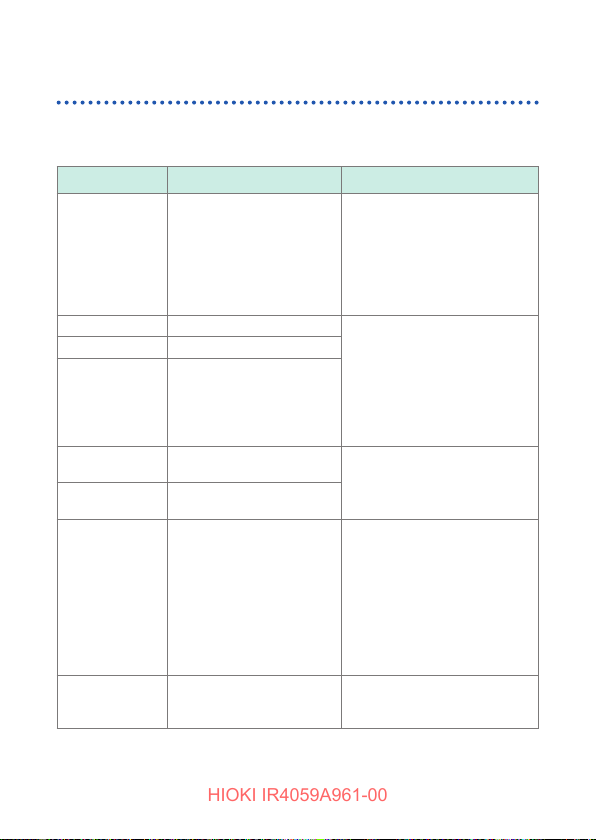
Troubleshooting
HIOKI IR4059A961-00
Errors and status codes
When an error is displayed on the LCD screen, repair is necessary.
Please contact your authorized Hioki distributor or reseller.
Code Description Remedy and Reference
• Verify that there is no broken
connection in the test leads.
• Zero adjustment can be
performed for readings of
up to 3
. Ensure that the
Ω
wiring resistance is 3
less. (p. 48)
Repair is required.
Replace the batteries.
If there is no apparent
improvement, the instrument
needs repair
Take the following actions
(p. 33):
• Reinstall the Z3210.
• Install a different Z3210.
If the error persists, you are
experiencing a instrument
failure. Contact your
authorized Hioki distributor or
reseller to organize repair.
Use GENNECT Cross to
update the rmware again.
(p. 70)
or
Ω
Err 0ΩADJ
Err1
Err2
Err4
Err5 01
Err5 02
Err8
Err9
Zero adjustment is outside
the allowable range.
(Low resistance
measurement)
Program data corrupt.
Adjustment data damaged.
The EEPROM used to
store settings data has
failed (including failure
to communicate with the
EEPROM).
Abnormality in
measurement circuit.
Abnormality in voltage
generation circuit.
Z3210 communications
error
(connection failure; Z3210
or hardware failure)
Firmware update error
80
Page 81
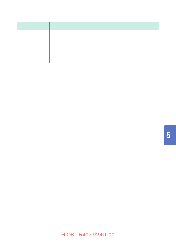
Code Description Remedy and Reference
HIOKI IR4059A961-00
FUSE (blinks)
APS → P.oFF
bAtt → P.oFF
The protective fuse has
tripped. (The fuse is user-
replaceable.)
Powered off by APS. –
Instrument powered off
due to supply voltage drop
Replace the indicated fuse.
(p. 27)
Replace the batteries.
(p. 27)
Troubleshooting
81
Page 82

Troubleshooting
HIOKI IR4059A961-00
82
Page 83

Appendix
HIOKI IR4059A961-00
Appx. 1 Measurement Principles
1. Insulation resistance measurement
The measuring object’s insulation resistance Rx is calculated by applying a
voltage V to the object, measuring the leak current I that ows to the object as
a result, and dividing the voltage V by the leak current I.
2. Low resistance measurement
The measuring object’s resistance Rx is calculated by applying a current I
to the measuring object, measuring the voltage V that occurs between the
measurement terminals as a result, and dividing the voltage V by the current I.
Appx.
Appx.1
Page 84
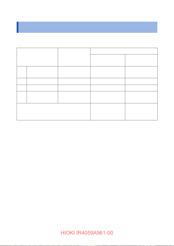
Operation Uncertainty
HIOKI IR4059A961-00
Appx. 2 Operation Uncertainty
The operation uncertainty and the variations of measurement value for the
respective inuence quantity approved by EN/IEC61557 are as follows:
Intrinsic uncertainty/
inuence quantity
Intrinsic
A
uncertainty
E2Supply voltage 4.5 V to 6.8 V ±4% rdg ±3% rdg ±2 dgt
E
Temperature 0°C to 35°C ±4% rdg ±3% rdg ±2 dgt
3
Operation
B
uncertainty
Guaranteed range of operation
Inuencing factor non-applicable for E1 and E4 to E
uncertainty
Operation
range
Reference
condition
resistance
1st effective
measurement
Variation
Insulation
±5% rdg ±3% rdg ±2 dgt
±12% rdg ±30% rdg
range
10
Low resistance
0.2
to 2
Ω
Ω
Appx.2
Page 85
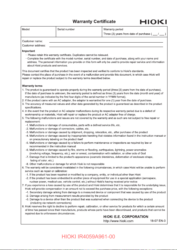
HIOKI IR4059A961-00
Page 86

 Loading...