


IR3455
Instruction Manual
HIGH VOLTAGE
INSULATION TESTER
EN
Dec. 2019 Revised edition 2
IR3455A961-02 19-12H
Find Quality Products Online at: sales@GlobalTestSupply.com
www.GlobalTestSupply.com

i
Contents
Introduction ...................................................... 1
Verifying Package Contents / Open the case ..1
Safety Information ...........................................5
Operating Precautions .....................................9
1 Overview 19
1.1 Product Overview .................................19
1.2 Features ............................................... 21
1.3 Measurement Overview .......................23
1.4 Names and Functions of Parts .............29
1.5 Screen Setup .......................................33
2 Measurement Preparations 35
2.1 Supplying Power ..................................35
2.1.1 Installing or Replacing the Battery...... 36
2.1.2 Installing the Battery Pack (Rechargeable
nickel-hydrogen battery)......................39
2.1.3 Connecting the AC Adapter................ 45
2.1.4 Charging the Battery Pack ................. 47
2.2 Turning Power On and Off ...................50
2.2.1 Auto Power Off................................... 51
2.3 Setting and Checking Date and Time ..52
2.3.1 Setting Date and Time........................ 52
2.3.2 Checking Date and Time.................... 55
2.4 Connecting Test Lead ..........................56
2.5 Connecting Temperature Sensor .........58
1
2
3
4
5
6
7
8
9
10
11
付録
IR3455A961-02
Find Quality Products Online at: sales@GlobalTestSupply.com
www.GlobalTestSupply.com
索引

ii
3 Measurement 59
3.1 Pre-Operation Inspection .....................59
3.2 Measuring Insulation Resistance .........62
3.2.1 Starting Measurement......................... 64
3.2.2 Ending Measurement.......................... 70
3.2.3 Checking and Deleting Held Data....... 72
3.2.4 Automatic Discharge Function............ 73
3.2.5 Switching to Leakage Current Indication
.............................................................74
3.2.6 Insulation Resistance Measurement
Basis....................................................75
3.2.7 Use of GUARD Terminal..................... 77
3.3 Measuring Voltage ...............................79
3.4 Measuring Temperature .......................82
3.4.1 Measurement Procedure .................... 82
4 Advanced Measurement 85
4.1 Using Timer ..........................................85
4.1.1 Setting Timer/Conducting Insulation
Resistance Measurement....................85
4.2 Displaying PI and DAR .........................89
4.3 Temperature Compensation (TC) ........93
4.3.1 Performing Temperature Compensation
.............................................................93
4.3.2 Exiting Temperature Compensation
Mode....................................................96
4.4 Step Voltage Test .................................97
4.4.1 Setting and Conducting a Step Voltage
Test......................................................98
4.4.2 Viewing Detailed Data of Each Step after
Step Voltage Test ..............................101
4.4.3 Exiting Step Voltage Test Mode........ 103
Find Quality Products Online at: sales@GlobalTestSupply.com
www.GlobalTestSupply.com

5 Recording Measurement Data
(Memory Function) 105
iii
5.1 Recording Measurement Data ...........107
5.1.1 Manual Recording (Recording result of
one measurement session)...............107
5.1.2 Logging Recording
(Recording at regular intervals)......... 110
5.2 Checking Recorded Data ...................118
5.3 Deleting Recorded Data .....................123
5.3.1 Deleting Data of Chosen No............. 123
5.3.2 Deleting all Data............................... 124
6 Other Functions 125
6.1 Changing and Checking Interval Setting
for PI Calculation.................................125
6.1.1 Changing Interval Setting................. 125
6.1.2 Checking Interval Setting ................. 127
6.2 Changing and Checking Voltage
Application Time for Step Voltage Test
............................................................128
6.2.1 Changing Time Setting..................... 128
6.2.2 Checking Time Setting..................... 130
6.3 Entering Temperature and Humidity
Measured with External Thermometer and
Hygrometer.........................................131
6.3.1 Entering and Saving......................... 132
6.3.2 Clearing Indications of Temperature and
Humidity Stored Data........................135
6.4 Communicating with PC .....................136
6.4.1 Installing Data Analysis Software
for 3455.............................................137
6.4.2 Installing Driver................................. 138
6.4.3 Downloading Data to Save to PC/ Setting
up Instrument on PC .........................139
1
2
3
4
5
6
7
8
9
10
11
付録
索引
Find Quality Products Online at: sales@GlobalTestSupply.com
www.GlobalTestSupply.com

iv
7 Specifications 141
7.1 General Specifications .......................141
7.2 Measurement Specifications ..............147
7.2.1 Insulation Resistance Measurement. 147
7.2.2 Leakage Current Measurement ........ 150
7.2.3 Voltage Measuremen t....................... 151
7.2.4 Temperature Measurement .............. 152
7.3 9750-01/-02/-03/-11/-12/-13 and
9751-01/-02/-03 ALLIGATOR CLIPs
Specifications......................................153
8 Maintenance and Service 155
8.1 Troubleshooting .................................156
8.2 Cleaning ............................................. 158
8.3 Error Display ......................................158
8.4 Performing System Reset ..................160
8.5 Discarding the Instrument ..................161
Appendix 165
Appendix 1Test Voltage
Characteristic Graph...........................165
Appendix 2Example of Insulation Resistance
Criteria.................................................166
Appendix 3Example of PI Criteria
(Polarization Index).............................166
Appendix 4Temperature Compensation Table
............................................................167
Find Quality Products Online at: sales@GlobalTestSupply.com
www.GlobalTestSupply.com
Introduction
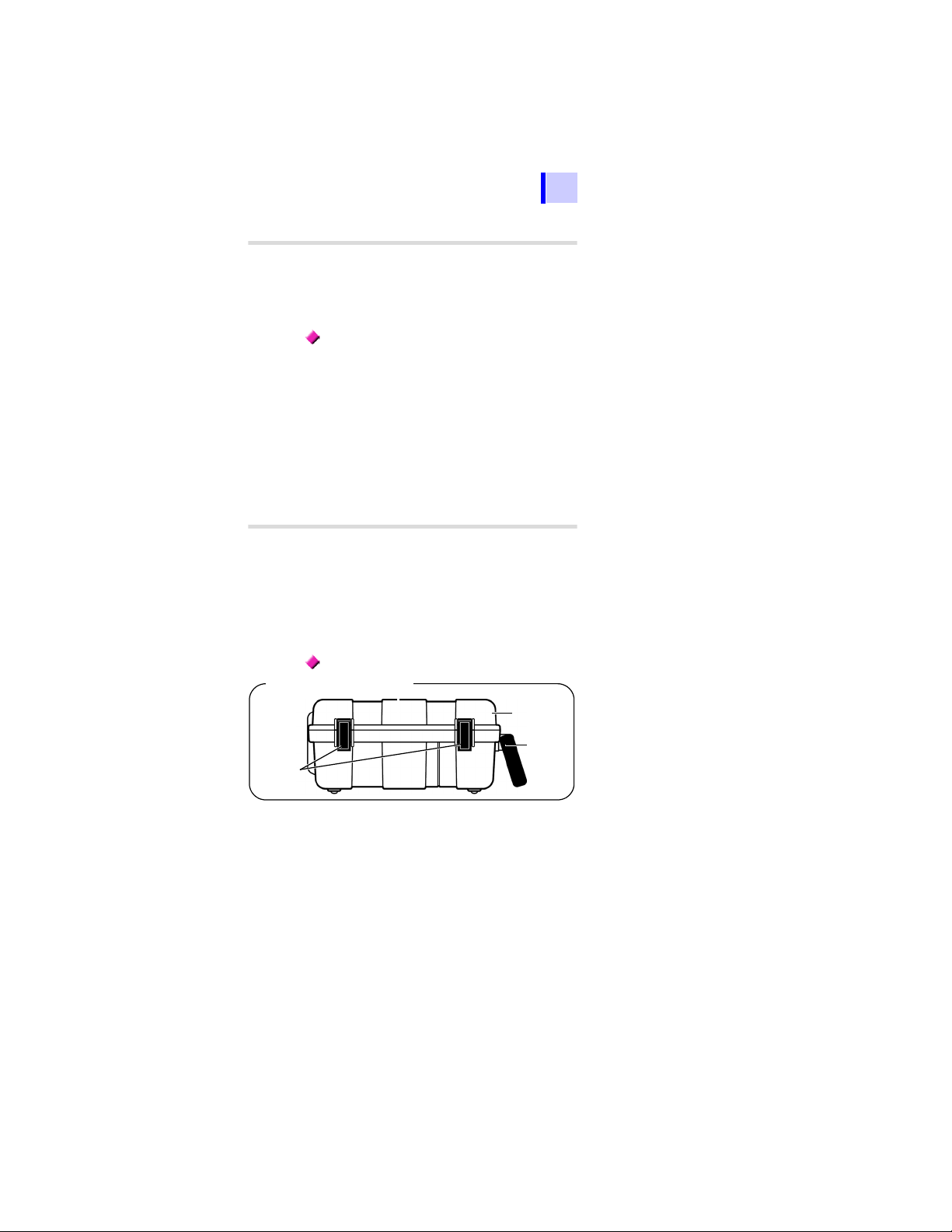
Appearance of Case
Cover
Latches
Handle
Thank you for purchasing the Hioki IR3455
High Voltage Insulation Tester. To obtain
maximum performance from the instrument, please read this manual first, and
keep it handy for future reference.
Trademarks
• Microsoft and Windows are either registered trademarks or trademarks of
Microsoft Corporation in the United States
and other countries.
• Adobe and Adobe Reader are either
trademarks or registered trademarks of
Adobe Systems Incorporated in the
United States and other countries.
Introduction
1
1
2
3
4
V erifying Package Contents / Open the case
When you receive the instrument, inspect it
carefully to ensure that no damage
occurred during shipping. In particular,
check the accessories, panel switches, and
connectors. If damage is evident, or if it fails
to operate according to the specifications,
contact your authorized Hioki distributor or
reseller.
Open the case
Open the case by releasing the two latches.
(See next page.)
5
6
7
8
9
10
11
付録
索引
Find Quality Products Online at: sales@GlobalTestSupply.com
www.GlobalTestSupply.com

2
Verifying Package Contents / Open the case
Procedure
1. Draw the latch outwards with your fin-
ger.
2. While raising the entire latch, place a
finger on the top of the latch and pull
it out.
Find Quality Products Online at: sales@GlobalTestSupply.com
www.GlobalTestSupply.com

Verifying Package Contents / Open the case
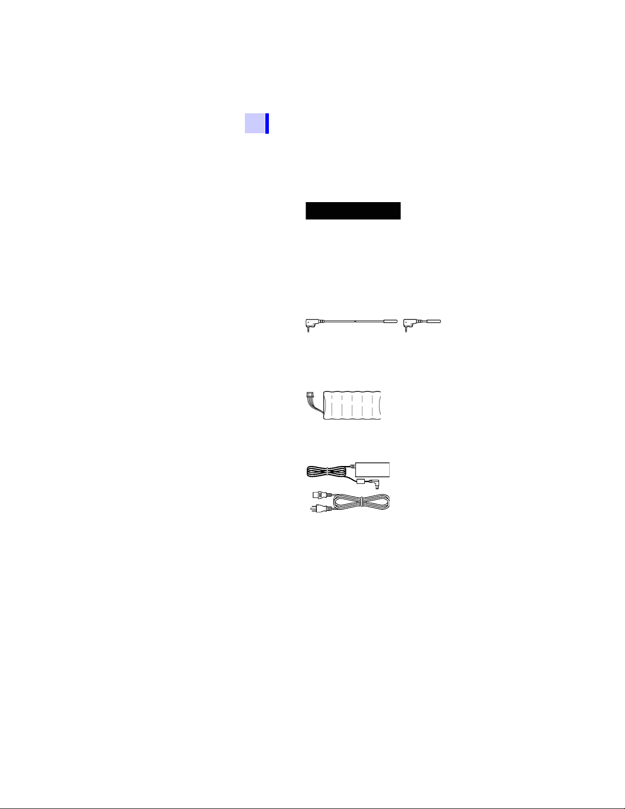
IR3455 HIGH VOLTAGE INSULATION TESTER × 1
9750-01,-02,-03 TEST LEAD (Red, Black, Blue)
Lead length Approx. 3 m
× 1 each
LR6 alkaline battery × 6Instruction Manual
(This book)
× 1
USB Cable
× 1
9751-01,-02,-03 ALLIGATOR CLIP (Red, Black, Blue)
× 1 each
CD (Data Analysis
Software for 3455)*
× 1
Main Unit
Accessories
3
1
2
3
4
5
6
7
8
*The latest version can be downloaded
from our web site.
9
10
11
付録
索引
Find Quality Products Online at: sales@GlobalTestSupply.com
www.GlobalTestSupply.com
4
Verifying Package Contents / Open the case
Options
The following options are available for the instrument. Contact
your authorized Hioki distributor or reseller when ordering.
The options are subject to change. Visit our website for
updated information.
9750-1 1, -12,-1 3 TEST LEAD
(Red, Black, Blue Lead length Appro x. 10 m)
The specifications for the 9750-11 and
9750-12 models differ from the standard
specifications in regards to temperature
characteristics.
See 7.2"Measurement Specifications" (page
147).
9631-01,-05 TEMPERA TURE SENSOR
Used for temperature measurement.
9631-01: Lead length Approx. 1 m
9631-05: Lead length Approx. 5 cm
9459 BATTERY PACK
(Rechargeable nickel-hydrogen battery)
The AC adapter is required for charging.
9753 AC ADAPTER
9418-15 AC ADAPTER
Input: 100 to 240 VAC
Output: 12 V DC
Find Quality Products Online at: sales@GlobalTestSupply.com
www.GlobalTestSupply.com

Safety Information
5
Safety Information
This instrument is designed to conform to IEC 61010 Safety
Standards, and has been thoroughly tested for safety prior
to shipment. However, using the instrument in a way not
described in this manual may negate the provided safety
features.
Before using the instrument, be certain to carefully read the
following safety notes:
1
2
Mishandling during use could result in
injury or death, as well as da mage to the
instrument. Be certain that you understand the instructions and precautions in
the manual before use.
• Protective gear
This instrument measures live lines. To
prevent electric shock, use appropriate
protective insulation and adhere to
applicable laws and regulations.
• With regard to the electricity supply,
there are risks of electric shock, heat
generation, fire, and arc flash due to
short circuits. Individuals using an electrical measuring instrument for the first
time should be supervised by a technician who has experience in electrical
measurement.
3
4
5
6
7
8
9
10
11
付録
索引
Find Quality Products Online at: sales@GlobalTestSupply.com
www.GlobalTestSupply.com

6
Safety Information
Symbols on the instrument
Indicates cautions and hazards. When the symbol is
printed on the instrument, refer to a corresponding
topic in the Instruction Manual.
Indicates that dangerous voltage may be present at
this terminal.
Indicates a double-insulated device.
Indicates DC (Direct Current).
Indicates AC (Alternating Current).
Symbols for standards
Indicates that the product conforms to regulations
set out by the EC Directive.
Indicates the Waste Electrical and Electronic Equipment Directive (WEEE Directive) in EU member
states.
Find Quality Products Online at: sales@GlobalTestSupply.com
www.GlobalTestSupply.com

Safety Information
Notation
In this document, the risk seriousness and the hazard levels
are classified as follows.
Indicates an imminently hazardous situation that will
result in death or serious injury to the operator.
Indicates a potentially hazardous situation that may result in death or serious injury to the operator.
Indicates a potentially hazardous situation that may result in minor or moderate injury to the oper ator or da mage to the instrument or malfunction.
Indicates advisory items related to performance or correct operation of the instrument.
Indicates a high voltage hazard.
If a particular safety check is not performed or the instrument is mishandled, this may give rise to a hazardous situation; the operator may receive an electric
shock, may get burnt or may even be fatally injured.
Indicates prohibited actions.
Indicates the location of reference information.
Indicates quick references for operation a nd remedies
for troubleshooting.
Additional information is presented below.
*
The instrument screen displays the alphanumeric characters as follows.
7
1
2
3
4
5
6
7
8
Accuracy
We define measurement tolerances in terms of rdg. (reading) and dgt. (digit) values, with the following meanings:
dgt.
(resolution)
rdg.
(reading or
displayed value)
The smallest displayable unit on a digital measuring instrument, i.e., the input value that
causes the digital display to show a "1" as the
least-significant digit.
The value currently being measured and indicated on the measuring instrument.
9
10
11
付録
索引
Find Quality Products Online at: sales@GlobalTestSupply.com
www.GlobalTestSupply.com

8
Safety Information
Measurement categories
To ensure safe operation of measuring instruments, IEC
61010 establishes safety standards for various electrical
environments, categorized as CAT II to CAT IV, and called
measurement categories.
• Using a measuring instrument in an
environment designated with a highernumbered category than that for which
the instrument is rated could result in a
severe accident, and must be carefully
avoided.
• Never use a measuring instrument that
lacks category labeling in a CA T II to CAT
IV measurement environment. Doing so
could result in a serious accident.
CAT II Primary electrical circuits in equipment con-
CAT III Primary electrical circuits of heavy equip-
CAT IV The circuit from the service drop to the ser-
nected to an AC electrical outlet by a power
cord (portable tools, household appliances,
etc.) CAT II covers directly measuring electrical outlet receptacles.
ment (fixed installations) connected directly
to the distribution panel, and feeders from
the distribution panel to outlets.
vice entrance, and to the power meter and
primary overcurrent protection device (distribution panel).
Find Quality Products Online at: sales@GlobalTestSupply.com
www.GlobalTestSupply.com

Operating Precautions
Preliminary Checks
Precautions during shipment
9
Operating Precautions
Follow these precautions to ensure safe operation and to
obtain the full benefits of the various functions.
1
Before using the instrument, verify that it
operates normally to ensure that no damage occurred during storage or shipping. If
you find any damage, contact your authorized Hioki distributor or reseller.
If the test lead or the instrument is damaged, there is a risk of electric shock.
Perform the following inspection before
using the instrument:
• Before using the instrum ent check that
the coating of the test leads are neither
ripped nor torn and that no metal parts
are exposed. Using the instrument
under such conditions could result in
electric shock. Replace the test leads
with those specified by our company.
• Verify that the instrument operates normally to ensure that no damage
occurred during storage or sh ipping. If
you find any damage, contact your
authorized Hioki distributor or reseller.
• To prevent an electric shock, confirm
that the white or red portion (insulation
layer) inside the cable is not exposed. If
a color inside the cable is exposed, do
not use the cable.
During shipment of the instrument, handle it
carefully so that it is not damaged due to a
vibration or shock.
2
3
4
5
6
7
8
9
10
11
付録
索引
Find Quality Products Online at: sales@GlobalTestSupply.com
www.GlobalTestSupply.com

10
Placement
Operating Precautions
Operating temperature and humidity range: P.141
Temperature and humidity range for guaranteed accuracy:
P.149 to P.151
Installing the instrument in inappropriate
locations may cause a malfunction of
instrument or may give rise to an accident. Avoid the following locations:
• Exposed to direct sunlight or high temperature
• Exposed to corrosive or combustible
gases
• Exposed to a strong electromagnetic
field or electrostatic charge
• Near induction heating systems (such
as high-frequency induction heating
systems and IH cooking equipment)
• Susceptible to vibration
• Exposed to water, oil, chemicals, or solvents
• Exp osed to high humidity or condensation
• Exposed to high quantities of dust particles
Find Quality Products Online at: sales@GlobalTestSupply.com
www.GlobalTestSupply.com
Operating Precautions
Shutter
11
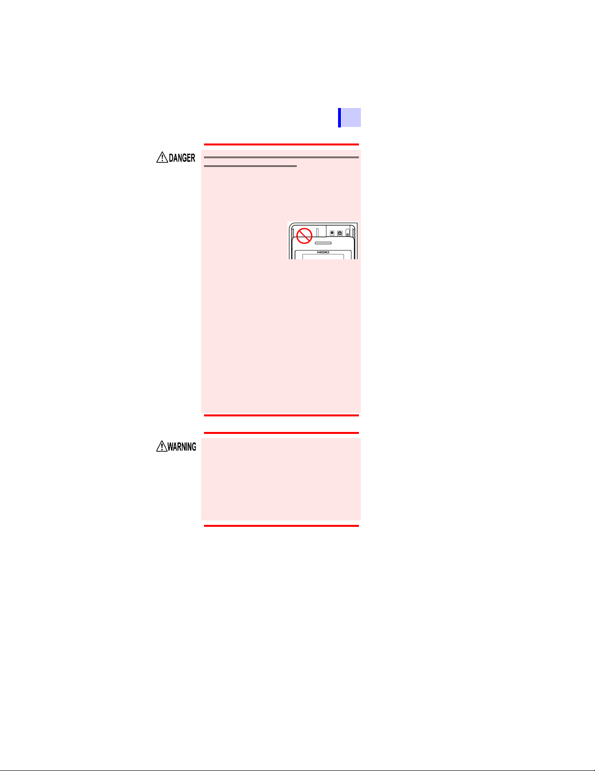
Observe the following to avoid electric
shock and short circuits.
• Before connecting or disconnecting the
test leads to/from the instrument, be
sure to disconnect the test leads from
the object under test and turn off power.
• Do not perform measurement with the
battery cover removed.
• Do not use the shutter if it is broken.
• To avoid electric
shock, do not
remove the instrument's case. The internal components of the instrument carry
high voltages and may become very hot
during operation.
• Do not use the instrument in environments containing ignitable gases,
explosive powders, etc. (Risk of explosion)
• Do not place the instrument on an
unstable table or an inclined place.
Dropping or knocking down the instrument can cause injury or damage to the
instrument.
• Do not use the instrument with circuits
that exceed its ratings or specifications.
Doing so may damage the instrument or
cause it to become hot, resulting in
bodily injury/electric shock.
1
2
3
4
5
6
7
8
9
• Before using the instrument, inform
those around you of your intention to
do so.
• To prevent instrument damage or
electric shock, use only the screw for
securing the battery cover in place that
are originally installed. If you have lost
a screw or find that a screw is damaged,
please contact your Hioki distributor for
a replacement.
10
11
付録
索引
Find Quality Products Online at: sales@GlobalTestSupply.com
www.GlobalTestSupply.com

12
Operating Precautions
• This instrument is designed for use indoors.
It can be operated at temperatures
between -10 to 50°C (14 to 122
°F
) without
degrading safety.
• To avoid damage to the instrument, protect
it from physical shock when transporting
and handling. Be especially careful to avoid
physical shock from dropping.
• If the protective fu nctions of the instrument
are damaged, either remove it from service
or mark it clearly so that others do not use it
inadvertently.
• Touching any of the high-voltage points
inside the instrument is very dangerous.
Customers are not allowed to modify, disassemble, or repair the instrument. Doing so
may cause fire, electric shock, or injury.
• Place the cover on the instrument when not in
use.
• To avoid damage to the instrument, do not
connect an external device to the USB terminal or the temperature sensor terminal .
• The cable is hardene d under the 0 degree
or colder environment. Do not bend or pull
it to avoid tearing its shield or cutting cable.
• This instrument is not drip-proof. Water
droplets on the grip or connector may result
in malfunctions.
• The protection rating for the enclosure of
this device (based on EN60529) is *IP40.
This indicates the degree of protection pro vided by
the enclosure of the device against use in hazardous locations, entry of solid foreign objects, and the
ingress of water.
4: Protected against access to hazardous parts with
wire measuring 1.0 mm in diameter. The equipment
inside the enclosure is protected against entry by
solid foreign objects larger than 1.0 mm in diameter.
0: The equipment inside the enclosure is not protected against the harmful effects of water.
Find Quality Products Online at: sales@GlobalTestSupply.com
www.GlobalTestSupply.com

Operating Precautions
13
• After use, always turn off the power.
• Standby State
The use of "standby state" in this manual
means that measurement is not being
performed and that no parameters are
set. This includes the state in which
is on.
• If the instrument is exposed to an abrupt
large variation in temperature,
condensation may occur, resulting in
measurement errors.
Leave the instrument in a new
environment for a while before starting
measurement.
1
2
3
4
5
6
7
8
9
10
11
付録
索引
Find Quality Products Online at: sales@GlobalTestSupply.com
www.GlobalTestSupply.com
14
Measurement
Operating Precautions
• It is recommend to mak e measurements
on the secondary side of distribution
panels. Measuring the primary side,
where the current capacity is much
larger, could cause damage to the
instrument or panel in the event of a
short-circuit.
• Do not short the two measurement lines
with the metal portion of the tips of the
test leads. Doing so may cause arcing
or otherwise result in a serious
accident.
• To avoid short circuit or electric shock,
do not touch the metal parts of the
connecting cable clips.
• To prevent electric shock, when measuring the voltage of a power line use
only the specified test lead.
• The optional test leads provided with
this instrument conform to the safety
standard EN61010. Use a test lead in
accordance with its defined measurement category and rated voltage.
• To prevent an electric shock, do not
exceed the lower of the ratings shown
on the instrument and test leads.
To avoid damage to the instrument, do not
apply voltage or current to temperature
probe.
Find Quality Products Online at: sales@GlobalTestSupply.com
www.GlobalTestSupply.com

Operating Precautions
Electrical Units
CD precautions
Handling the Battery Pack
15
1 T (Tera ohm) =1000 G =1012
1 G (Giga ohm) =1000 M =10
1 M(Mega ohm) =1000 k =10
1 mA (Milliampere) =0.001 A =10
1 A (Micro ampere) =0.001 mA =10
1 nA (Nano ampere) =0.001 A=10
• Exercise care to keep the recorded side
of discs free of dirt and scratches. When
writing text on a disc's label, use a pen or
marker with a soft tip.
• Keep discs inside a protective case and
do not expose to direct sunlight, high temperature, or high humidity.
• Hioki is not liable for any issues your
computer system experiences in the
course of using this disc.
Be sure to observe the following precautions. Incorrect handling may result in
liquid leaks, heat generation, ignition,
bursting and other hazards:
• The battery pack contains lye, which
may cause blindness if it comes into
contact with the eyes. Should battery
liquid get into your eyes, avoid rubbing
them. Flush them with water and seek
immediate medical attention.
• When storing the instrument, make sure
no objects that could short-circuit the
connectors are placed near them.
9
6
-3
A
-6
A
-9
A
1
2
3
4
5
6
7
8
9
10
11
付録
索引
Find Quality Products Online at: sales@GlobalTestSupply.com
www.GlobalTestSupply.com

16
Operating Precautions
Observe the following to avoid damage to
the instrument:
• Use the battery pack in an ambient temp erature range of 0 to 40°C and charge it in an
ambient temperature range of 0 to 40°C.
• If the battery pack fails to finish charging
within the stipulated time, disconnect the
AC adapter to stop charging and contact
your dealer or Hioki representative.
• Consu lt your dealer or nearest service station should liquid leaks, strange odor, heat,
discoloration, deformation and other abnormal conditions occur during use, charging
or storage. Should these conditions occur
during use or charging, turn off and disconnect the instrument immediately.
• Do not expose the instrument to water and
do not use it in excessively humid locations
or locations exposed to rain.
• Do not expose the instrument to strong
impacts and do not throw it around.
Heed the following instructions to avoid battery performance drop or leakage.
• Do no mix o ld and new batteries, or different types of batteries.
• Pay attention to the polarity ma rkings "+-",
so that you do not insert the batteries the
wrong way around.
• Do not use batteries after their recommended expiry date.
• Do not leave a depleted batteries inside the
instrument.
• Replace batteries only with the specified
type.
• Remove the batteries or battery pack from
the instrument if it is to be stored for a long
time.
Find Quality Products Online at: sales@GlobalTestSupply.com
www.GlobalTestSupply.com

Operating Precautions
17
• The battery pack is a consumable. If you
are able to use the instrument for only a
limited period of time despite the battery
pack being properly charged, the battery
pack's service life is at an end, and it
should be replaced.
• When a battery pack that has not been
used for a long time is used, charging may
end before the battery pack is fully
charged. In such a case, repeat charging
and discharging a number of time before
use. (A battery pack may also be in such a
state immediately after purchase.)
• The life of the battery pack (when capacity
is 60% or more of initial capacity) is
approximately 500 charge-discharge
cycles. (The life differs depending on the
conditions of use.)
• To prevent battery pack deterioration
when the battery will not be used for 1
month or longer, remove it and store it in a
dry location with an ambient temperature
range of between -20°C to 30°C. Be sure
to discharge and charge it every two
months. Long-term storage at low battery
capacity will reduce performance.
• When a battery pack is used, the
instrument turns off automatically when
the capacity drops. Leaving the
instrument in this state for a long time may
lead to over discharge so be sure to turn
off the power switch on the instrument.
• The charging efficiency of the battery pack
deteriorates at high and low
temperatures.
1
2
3
4
5
6
7
8
9
10
11
付録
索引
Find Quality Products Online at: sales@GlobalTestSupply.com
www.GlobalTestSupply.com

18
Operating Precautions
Find Quality Products Online at: sales@GlobalTestSupply.com
www.GlobalTestSupply.com
1.1 Product Overview
Overview 1
19
1
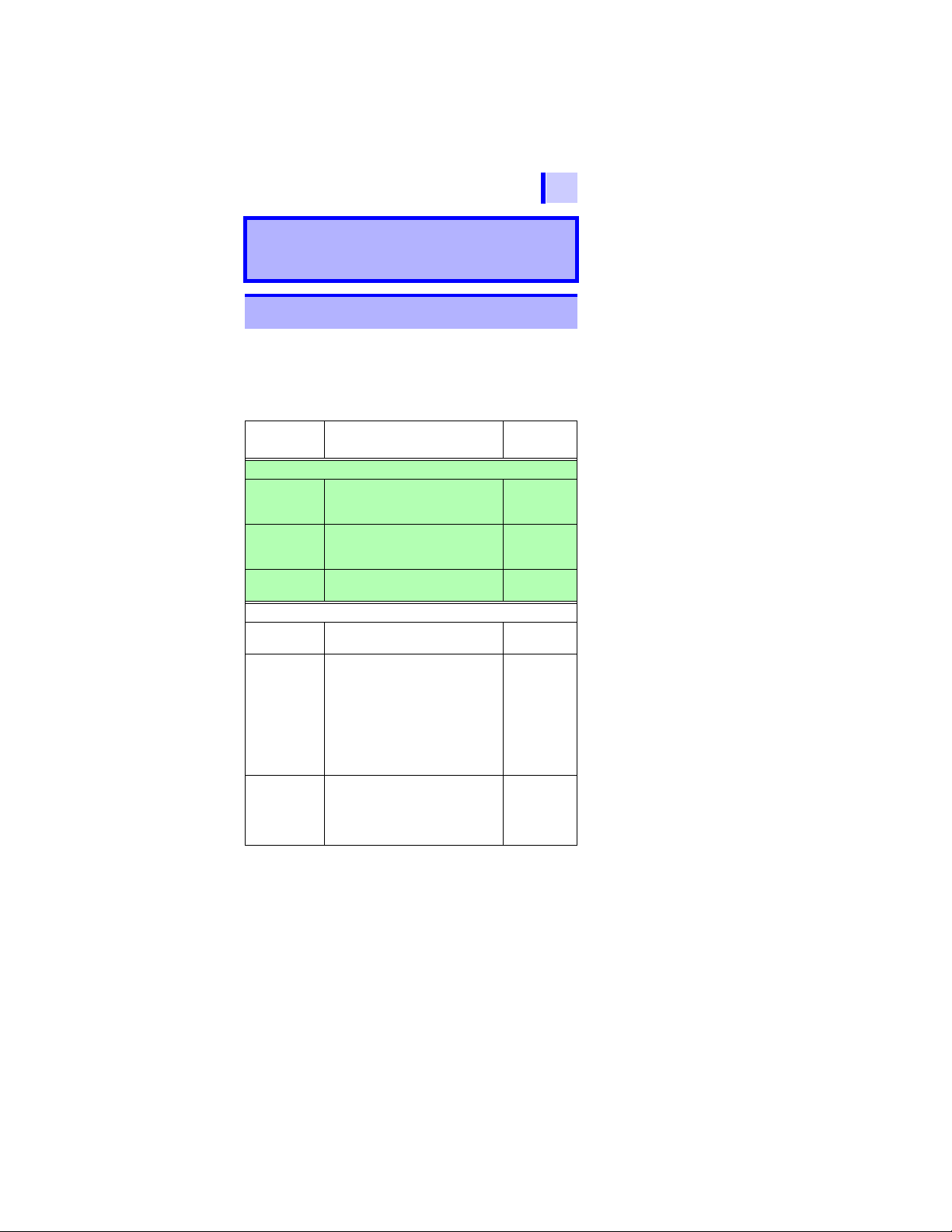
1.1 Product Overview
The IR3455 is an insulation resistance tester with a wide
measurement range, for use in such environments involving
low to high voltage.
The instrument has the functions and purposes given
below.
Function Purpose
(Basic)
Insulation
resistance
measurement
Voltage
measurement
Temperature
measurement
(Applied)
Timer To automatically end mea surement
Display
PI and DAR
values
Temperature
compensation (TC)
To test the insulation resistance of
an electrical facility.
To measure the voltage of an external circuit, e.g., commercial power
supply.
To measure a temperature 3.4 (P.82)
after a predetermined time.
To check whether the insulation re-
sistance increases with time after a
voltage is applied.
[When the PI (polarization index)
value or the DAR (dielectric absorption ratio) value is close to 1, the instrument determines that the
insulation of the object to be measured has deteriorated.]
To obtain the insulation resistance
at various temperatures varied fr om
the actual environmental temperature at which measurement is performed.
Reference
page
3.2 (P.62)
3.3 (P.79)
4.1 (P.85)
4.2 (P.89)
4.3 (P.93)
2
3
4
5
6
7
8
9
10
11
付録
索引
Find Quality Products Online at: sales@GlobalTestSupply.com
www.GlobalTestSupply.com

20
1.1 Product Overview
Function Purpose
Step voltage
test
Memory
PC
Communication
To determine whether the insulation resistance of an object changes according to test voltage
applied.
To save the measurement data.
To create tables or graphs of the
data saved in the memory for reports, etc.
Reference
page
4.4 (P.97)
5 (P.105)
6.4 (P.136)
Find Quality Products Online at: sales@GlobalTestSupply.com
www.GlobalTestSupply.com

1.2 Features
1.2 Features
21
Wide test voltage range
Generates a wide range of test voltages, from
250 V to 5 kV
The voltage may be chosen from the commonly used presets of 250 V, 500 V, 1 kV, 2.5
kV, and 5 kV; or set to a desired level by
increments or decrements o f 25 V or 100 V.
3.2 "Measuring Insulation Resistance" (page 62)
Insulation diagnoses
For automatic calculation and indication of
PI (polarization index) and DAR (dielectric
absorption ratio), step voltage testing, and
temperature compensation.
4 "Advanced Measurement" (page 85)
Large memory
Stores up to 100 manual records and 10
logging records. The stored data may be
displayed on the LCD or downloaded to a
PC.
5 "Recording Measurement Data ( Mem or y Func-
tion)" (page 105)
6.4 "Communicating with PC" (page 136)
Large, clear display
The large display provides easy viewing.
Measurements may also be displayed
using a logarithmic bar graph, offering the
feel of an analog meter.
The LCD is backlit, enabling measurement
in poor lighting conditions.
1
2
3
4
5
6
7
8
9
10
11
付録
索引
Find Quality Products Online at: sales@GlobalTestSupply.com
www.GlobalTestSupply.com

22
1.2 Features
PC software with report creation/
printing feature
The instrument has a USB interface. Data
stored in the memory may be downloaded
to PC using the data download software.
The same software also enables reports to
be created and printed with ease.
6.4 "Communicating with PC" (page 136)
Compact hard case
The case is durable-designed to withstand
the toughest of working conditions, compact, and highly portable.
Dual battery power supply
The instrument can be powered by either
alkaline or rechargeable nickel-hydrogen
batteries. (Selectable via switch)
2.1.1 "Installing or Replacing the Battery" (page
36)
2.1.2 "Installing the Battery Pack (Rechargeable
nickel-hydrogen battery)" (page 39)
Find Quality Products Online at: sales@GlobalTestSupply.com
www.GlobalTestSupply.com

1.3 Measurement Overview
Purpose : Inspection of high-voltage electrical
facilities
Location : High-voltage receiving station or trans-
forming station
Test object : Large motors, transformers, cables,
etc.
• Measures insulation resistance, voltage and temperature.
• Stores measurement data in the internal memory.
• Downloads data to a PC for table, graph, or report
creation.
Prepare for measurement
2 "Measurement Preparations" (page 35)
23
1.3 Measurement Overview
This instrument is designed for measurement of the follo wing:
Measurement condition
When measuring insulation resistance, ensure that power
supply to the object under test is turned off.
1
2
3
4
5
6
You will need:
• IR3455 HIGH VOLTAGE INSULATION TESTER
• AA alkaline batteries (LR6), or
9459 BATTERY PACK
• 9750-01,-02,-03 TEST LEAD
• 9751-01,-02,-03 ALLIGATOR CLIP
• 9631-01,-05 TEMPERATURE SENSOR (for temperature
measurement)
Flow of measurement
Before starting measurement, check the following:
• The power supply method.
• The power ON/OFF method.
• That date and time are set.
• Connection of test leads, temperature sensor, and USB
cable.
7
8
9
10
11
付録
索引
Find Quality Products Online at: sales@GlobalTestSupply.com
www.GlobalTestSupply.com

24
Start measurement.
GUARD
terminal
Warning: Confirm that the power supply to the
object under test has been turned off.
Object to be measured (Ex.: Motor)
+ terminal
- terminal
Test lead (Red)
Attach to a metal
chassis or a ground
terminal.
Test lead (Black)
Attach to a metal part
of the power supply
terminal.
1.3 Measurement Overview
Insulation Resistance Measurement
3.2 "Measuring Insulation Resistance" (page 62)
Make sure that power supply to the object under
1.
test is turned off.
2.
Press the key to turn on
the instrument.
Connect the test leads into the
3.
"+" and "-" terminals of the instrument and to the object to be
tested.
2.2 (page 50)
2.4 (page 56)
3.2.1 (page 64)
Find Quality Products Online at: sales@GlobalTestSupply.com
www.GlobalTestSupply.com

1.3 Measurement Overview
4.
Press the key and set
the test voltage.
5.
Press the key to generate a voltage and start measure-
ment.
3.2.1 (page 64)
3.2.1 (page 64)
25
1
2
3
4
5
6
7
Read the indication.
6.
3.2.1 (page 64)
8
9
10
11
付録
索引
Find Quality Products Online at: sales@GlobalTestSupply.com
www.GlobalTestSupply.com

26
1.3 Measurement Overview
7.
Press the key to stop
voltage generation and measure-
ment.
3.2.2 (page 70)
The automatic discharge function
8.
is activated.
Measurement is terminated when
9.
the voltage falls below 10 V.
3.2.4 (page 73)
Find Quality Products Online at: sales@GlobalTestSupply.com
www.GlobalTestSupply.com
1.3 Measurement Overview
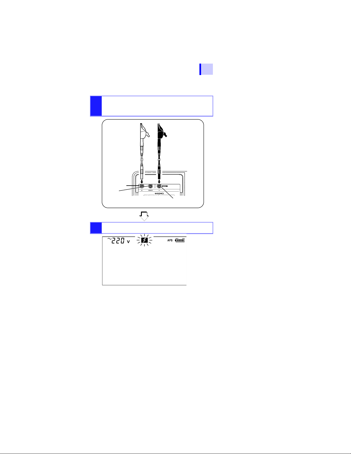
+ terminal
- terminal
GUARD
terminal
Test lead (Red) Test lead (Black)
Voltage Measurement
3.3 "Measuring Voltage" (page 79)
Connect the test leads into the "+" and "-" termi-
1.
nals of the instrument and to the object to be
tested.
Read the indication.
2.
27
1
2
3
4
5
6
7
8
9
10
11
付録
索引
Find Quality Products Online at: sales@GlobalTestSupply.com
www.GlobalTestSupply.com
28
Record measurement data
5 "Recording Measurement Data (Memory Function)"
1.3 Measurement Overview
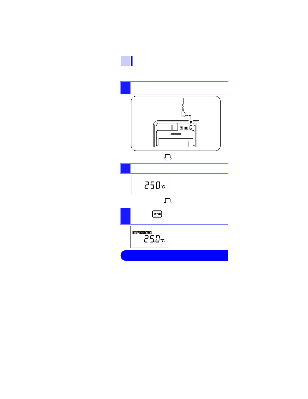
Temperature Measurement
3.4 "Measuring Temperature" (page 82)
Insert the temperature sensor into the tempera-
1.
ture sensor terminal of the instrument.
Read the indication.
2.
Press the key to stop temperature mea-
3.
surement.
Insulation resistance and temperature measurement data
are held after measurement is completed.
This data will be cleared if power is turned off. To store the
data, use the memory function.
Find Quality Products Online at: sales@GlobalTestSupply.com
www.GlobalTestSupply.com
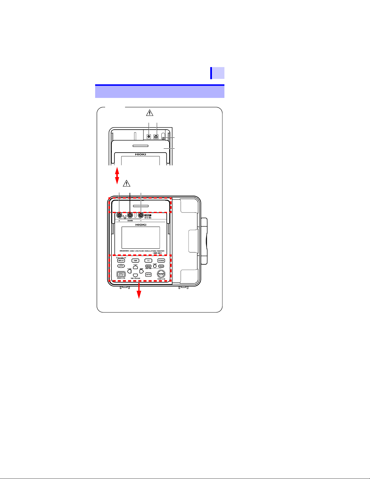
1.4 Names and Functions of Parts
1. 2.
3.
LCD
Slide the shutter.
Operating panel
(page 31)
4.
567
(page 9, page 45)
(page 9, page 56)
Front
1.4 Names and Functions of Parts
29
1
2
3
4
5
6
7
8
9
10
11
付録
索引
Find Quality Products Online at: sales@GlobalTestSupply.com
www.GlobalTestSupply.com
30
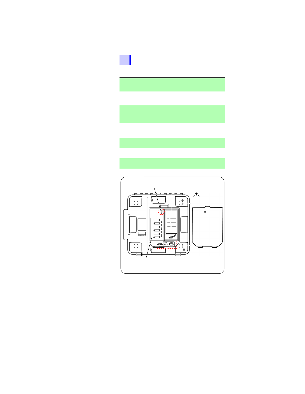
Back
Battery cover
Set screw
Battery pack compartment
(Under the battery cover)
Battery selector switch
(Under the battery cover)
Selects the type of battery.
AA alkaline batteries (LR6)
compartment
(Under the battery cover)
(page 9, page 36,
page 39)
1.4 Names and Functions of Parts
Name Function
AC adapter
1
terminal
2 USB terminal
Temperature
3
sensor
terminal
4Shutter
+ measurement
5
6
7
*
terminal
- measurement
*
terminal
GUARD
terminal
*These are referred to simply as + and - terminals.
Connect the AC adapter to this terminal.
2.1.3 "Connecting the AC Adapter" (page
45)
Connect the USB Cable to this terminal.
6.4.3 "Downloading Data to Save to PC/
Setting up Instrument on PC" (page 139)
Connect the temperature sensor to this terminal.
2.5 "Connecting Temperature Sensor"
(page 58)
Prevents connection to other terminals when
test leads are connected to the mea sur em en t
terminals - a safety feature.
Connect the red test lead to this terminal.
2.4 "Connecting Test Lead" (page 56)
Connect the black test lead to this terminal.
2.4 "Connecting Test Lead" (page 56)
Connect the blue test lead to this terminal.
3.2.7 "Use of GUARD Terminal" (page 77)
Find Quality Products Online at: sales@GlobalTestSupply.com
www.GlobalTestSupply.com
1.4 Names and Functions of Parts
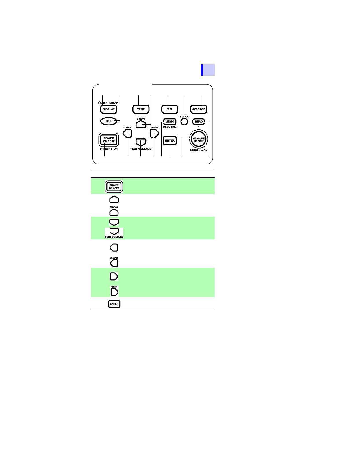
Operating panel
6. 7.
2.
1.
8. 9. 10.
13.
14.
15.
11.12.
5.3.4.
31
1
2
3
4
Key Function
1 Used to turn power on/off.
Used to set parameters.
2
3
4
5
6
Used to toggle between set voltage and monitor
voltage after resistance measurement.
Used to set parameters.
Used to set test voltage.
• Used to make fine adjustments to test voltage.
• Used to move the cursor to change units, values, etc.
• Used to display the date and time.
• Used to set the date and time.
• Used to make fine adjustments to test voltage.
• Used to move the cursor to change units, values, etc.
• Used to display the timer.
• Used to set the timer.
• Used to confirm entries.
• Used to stop temperature measurement.
5
6
7
8
9
10
11
付録
索引
Find Quality Products Online at: sales@GlobalTestSupply.com
www.GlobalTestSupply.com
32
Test lead and alligator clip
page 56
1.4 Names and Functions of Parts
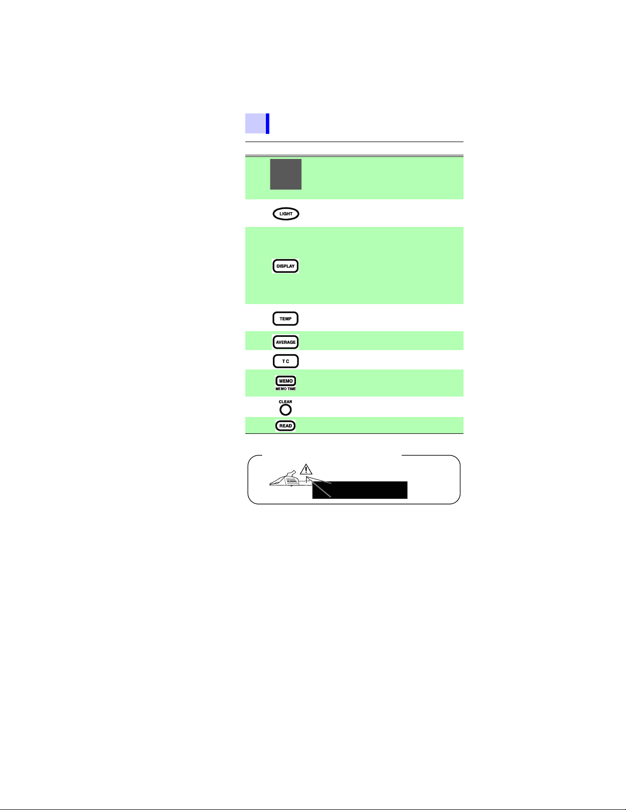
Key Function
• Used to start and stop of resistance measure-
7
(Warning lamp)
8
9
10
11
12
13
14 Used to delete data in the memory.
ment.
• Blinks when a voltage is generated.
• Blinks when a voltage of 50 V or more is input
or when discharging is performed.
• Turns the LCD backlight on/off.
• LCD backlight automatically extinguishes after
30 seconds.
• Changes measurement units on the LCD.
When measuring resistance:
•
This key toggles between display of current
and resistance on the LCD
•
When the resistance value is held:
This key changes LCD display in the following
sequence: resistance current DAR 1 min/
15s DAR 1 min/30s PI resistance
current ...
• Used to view held temperature data.
• Used to enter the temperature of an external
thermometer.
Used to reduce drift of resistance or current
reading.
Used to enter the temperature compensation
mode.
• Used to store data in the memory.
• Used to display the date and time data was
stored in the memory.
15 Used to display data in the memory.
Find Quality Products Online at: sales@GlobalTestSupply.com
www.GlobalTestSupply.com
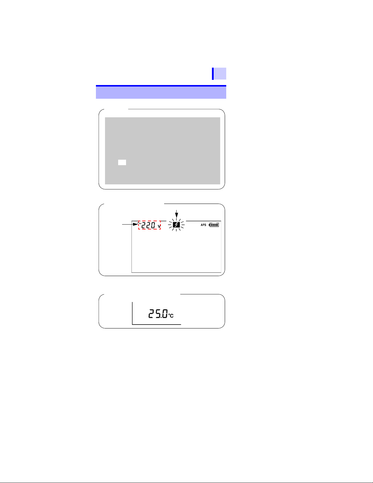
1.5 Screen Setup
All On
Measuring Voltage
Measured
voltage
Blinking
Measuring Temperature
1.5 Screen Setup
33
1
2
3
4
5
6
7
8
3.3 "Measuring Voltage" (page 79)
3.4 "Measuring Temperature" (page 82)
9
10
11
付録
索引
Find Quality Products Online at: sales@GlobalTestSupply.com
www.GlobalTestSupply.com

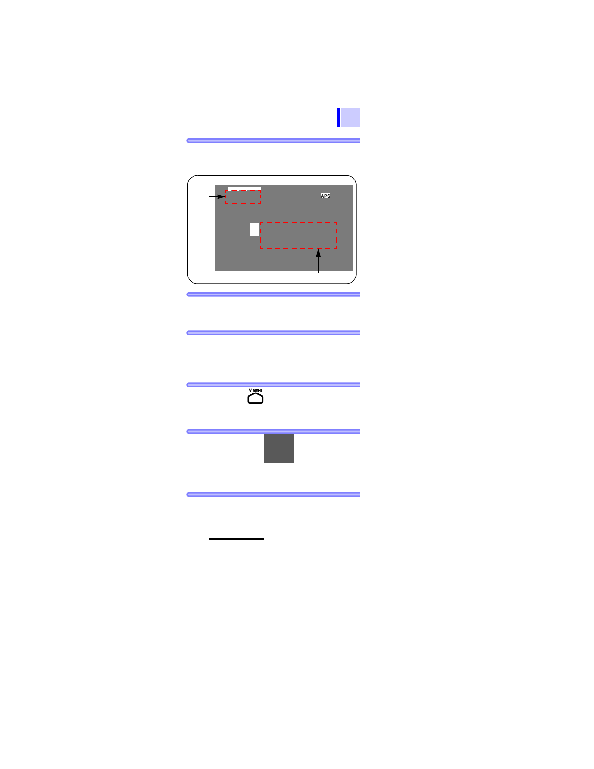
34
Measuring Insulation Resistance
Actual output
voltage
Blinking
> blinks if the
input exceeds
the measurement range.
Elapsed time Insulation resistance
The screen is switched over with the
key.
Leakage Current Display
Blinking
Elapsed time
Actual output
voltage
The bar graph
shows the
resistance
measurement.
< blinks at
below 1 nA.
Current measurement
1.5 Screen Setup
3.2 "Measuring Insulation Resistance" (page 62)
3.2.5 "Switching to Leakage Current Indication"
(page 74)
Find Quality Products Online at: sales@GlobalTestSupply.com
www.GlobalTestSupply.com

Measurement
2.1 Supplying Power
35
Preparations
2
2.1 Supplying Power
This instrument can be powered by the following:
• AA alkaline batteries (LR6)
See 2.1.1 "Installing or Replacing the Battery" (page 36).
• 9459 BATTERY PACK (Option)
See 2.1.2 "Installing the Battery Pack (Rechargeable nickel-hydro-
gen battery)" (page 39), and 2.1.4 "Charging the Battery Pack"
(page 47)
• 9753 AC ADAPTER or 9418-15 AC ADAPTER (Option)
See 2.1.3 "Connecting the AC Adapter" (page 45).
1
2
3
4
5
6
7
8
9
10
11
付録
索引
Find Quality Products Online at: sales@GlobalTestSupply.com
www.GlobalTestSupply.com
36
2.1 Supplying Power
2.1.1 Installing or Replacing the Battery
• To avoid electric shock, turn off the
power switch and disconnect the test
leads before replacing the batteries.
• Do not mix old and new batteries, or different types of batteries. Also, be careful to observe battery polarity during
installation. Otherwise, poor performance or damage from battery leakage
could result.
• After replacing the batteries, reattach
the battery cover and secure the screw
before using the instrument.
• Battery may explode if mistreated. Do
not short-circuit, recharge, disassemble
or dispose of in fire.
• Handle and dispose of batteries in
accordance with local regulations.
• When the battery status indicator
is low, replace the batteries.
• The indicator lights up when the
remaining battery capacity is low. In this
case, measurement is not possible.
Replace the batteries.
• Use the specified batteries only. Do not use
manganese batteries, for example, since
operating time will be greatly reduced.
• To avoid corrosion and damage to this
instrument from battery leakage, remove
the batteries from the instrument if it is to
be stored for a long time.
Find Quality Products Online at: sales@GlobalTestSupply.com
www.GlobalTestSupply.com

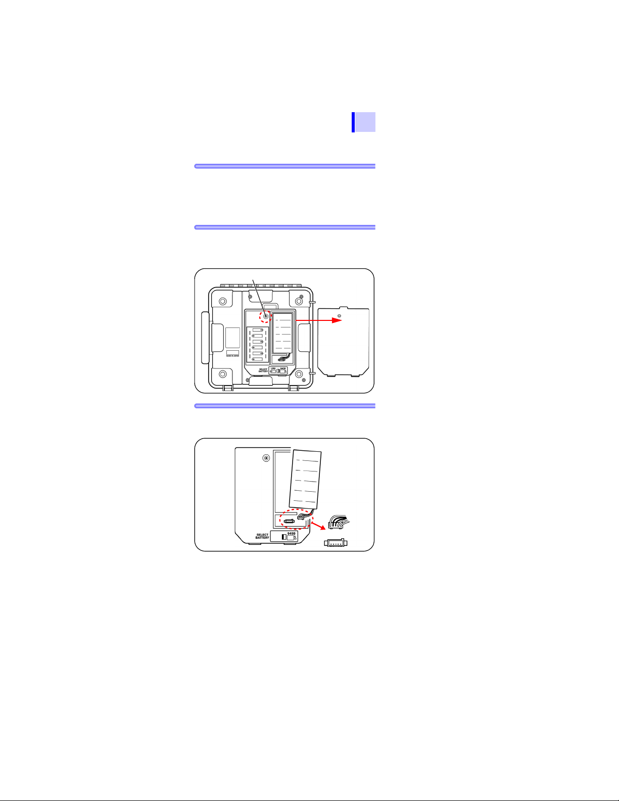
Procedure
Set screw
Remove
Battery
cover
2.1 Supplying Power
37
1. Turn off power and disconnect all the
test leads from the instrument.
See 2.2 "Turning Po wer On and Off" (page 50).
1
2. Loosen the set screw on the rear of the
instrument and remove the battery
cover.
3. Place six LR6 alkaline batteries into the
battery compartment. (Replace all six at
the same time)
2
3
4
5
6
7
8
9
10
11
付録
索引
Find Quality Products Online at: sales@GlobalTestSupply.com
www.GlobalTestSupply.com

38
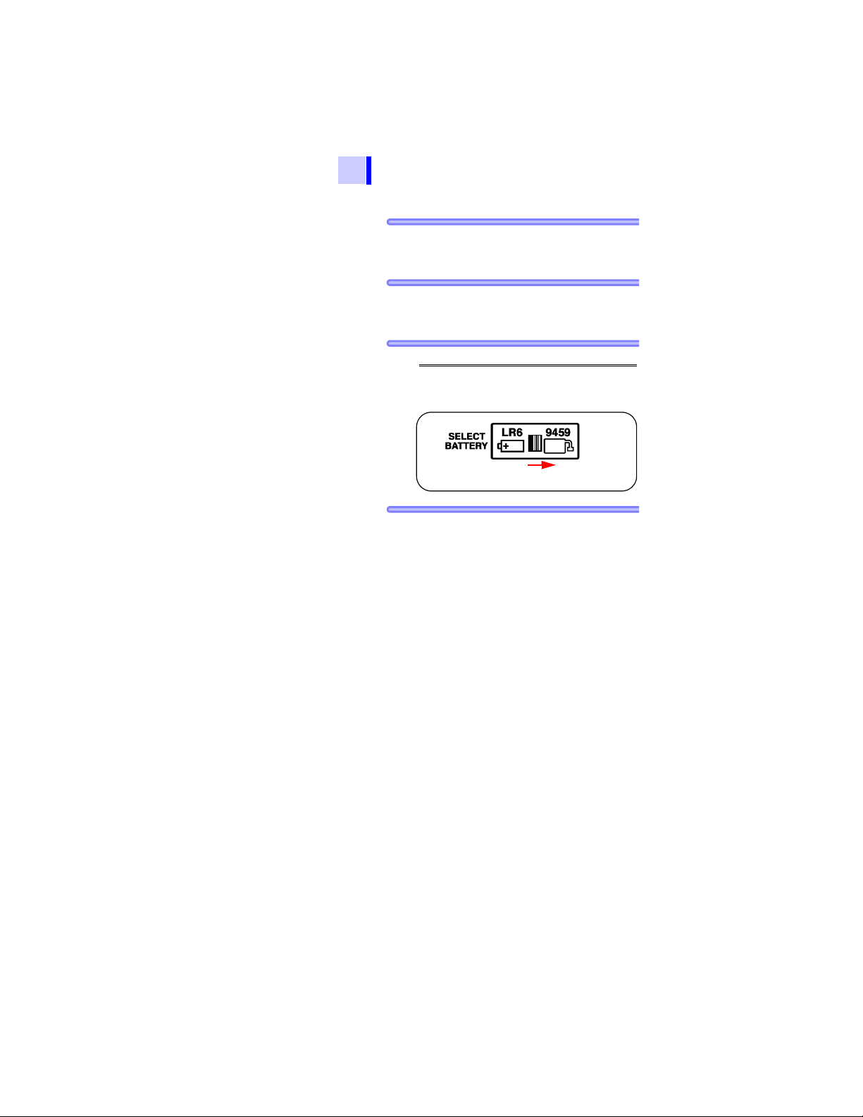
To LR6
2.1 Supplying Power
4. Turn the battery selector switch to LR6.
When the power is turned on, “Lr6” appears
on the top left of the screen.
See 2.2 "Turning Power On and Off" (page 50).
5. Replace the battery cover and tighten
the set screw.
Find Quality Products Online at: sales@GlobalTestSupply.com
www.GlobalTestSupply.com

2.1 Supplying Power
2.1.2 Ins talling the Battery Pack
(Rechargeable nickel-hydrogen battery)
• Use the optional 9459 BATTERY PACK. The operating
time is longer than that with alkaline batteries, and the
pack is rechargeable.
• Battery pack is dispatched in an uncharged state. Charge
before use.
ProcedureSee 2.1.4 "Charging the Battery Pack" (page 47).
• For battery operation, use only the Hioki
Model 9459 BATTERY PACK. We do not
take any responsibility for accidents or
damage related to the use of any other
batteries.
• To avoid heat buildup, rupture, or leakage of the battery, do not use if damaged, wires are exposed, or the battery/
instrument connector is damaged.
• To avoid electric shock, be sure to disconnect the test leads from the instrument, turn off power, and disconnect
the AC adapter from the instrument,
before installing or removing the battery
pack.
• Battery may explode if mistreated. Do
not short-circuit, disassemble or dispose of in fire. Do not recharge alkaline
batteries. Handle and dispose of batteries in accordance with local regulations.
Take care not to step on the battery pack
power cable, as this may damage it.
39
1
2
3
4
5
6
7
8
9
10
11
付録
索引
Find Quality Products Online at: sales@GlobalTestSupply.com
www.GlobalTestSupply.com

40
2.1 Supplying Power
Installation
Procedure
• If the battery pack is not used for an
extended period of time, remove it from the
instrument and store at a temperature
between -20 to 30°C, to prevent
deterioration.
Charge the battery at least every 2 months.
If the battery pack is left for a long period of
time in a low state of charge, its
performance will be degraded.
• When the battery status indicator is low,
charge the battery pack.
• The battery pack is subject to selfdischarge. Be sure to charge the battery
pack before initial use. If the battery
capacity remains very low after correct
recharging, the useful battery life is at an
end.
• The life of the battery pack is 500
charging cycles, i.e., about one year.
Tools: Phillips screwdriver
1.
Turn off power and disconnect the test leads,
AC adapter and USB cable from the instrument.
See 2.2 "Turning Power On and Off" (page 50).
Find Quality Products Online at: sales@GlobalTestSupply.com
www.GlobalTestSupply.com

2.1 Supplying Power
Set screw
Remove
Battery cover
41
2. Loosen the set screw on the rear of the
instrument and remove the battery
cover.
3. Connect the battery pack to the instru-
ment. (Align the protrusions.)
1
2
3
4
5
6
7
8
9
10
11
付録
索引
Find Quality Products Online at: sales@GlobalTestSupply.com
www.GlobalTestSupply.com

42
To 9459
2.1 Supplying Power
4. Place the battery pack in the battery
pack compartment.
5. Turn the battery selector switch to 9459.
When the power is turned on, “bP” appears
on the top left of the screen.
See 2.2 "Turning Power On and Off" (page 50).
6. Replace the battery cover and tighten the
set screw.
(Be careful not to catch the battery pack
cable in the battery cover, to prevent
damaged wiring.).
Find Quality Products Online at: sales@GlobalTestSupply.com
www.GlobalTestSupply.com
2.1 Supplying Power
Set screw
Remove
Battery cover
43
Replacement
Procedure
1. Turn off power and disconnect the test
2. Loosen the set screw on the rear of the
3.
Tools: Phillips screwdriver
leads, AC adapter, and USB cable from
the instrument.
See 2.2 "Turning Po wer On and Off" (page 50).
instrument and remove the battery
cover.
Disconnect the plug of the battery pack
from the connector of the instrument.
1
2
3
4
5
6
7
8
9
10
11
付録
索引
Find Quality Products Online at: sales@GlobalTestSupply.com
www.GlobalTestSupply.com
44
To 9459
2.1 Supplying Power
4.
Connect the new battery pack to the instrument. (Align the protrusions.)
5. Place the battery pack in the battery
pack compartment.
6. Turn the battery selector switch to 9459.
When the power is turned on, “bP” appears
on the top left of the screen.
See 2.2 "Turning Power On and Off" (page 50).
7. Place the battery cover and tighten the
screw.
Find Quality Products Online at: sales@GlobalTestSupply.com
www.GlobalTestSupply.com
2.1 Supplying Power
1
2 Move the shutter.
3
4
45
2.1.3 Connecting the AC Adapter
• Optional AC adapter can be used.
• When the AC adapter is connected to the instrument, you
can charge the battery pack, communicate with a PC, perform temperature measurement, and edit the settings.
However, you cannot measure insulation resistance, leakage current or voltage.
1
2
Procedure
• Turn the instrument off before connecting the AC adapter to the instrument
and to AC power.
• Use only the spe cified AC adapter. AC
adapter input voltage range is 100 V to
240 V AC at 50 Hz/60 Hz. To avoid electrical hazards and damage to the instrument, do not apply voltage outside of
this range.
• To avoid electrical accidents and to
maintain the safety specifications of
this instrument, connect the power cord
provided only to an outlet.
The AC adapter cannot be used when
performing measurement using instrument
leads.
3
4
5
6
7
8
9
10
11
付録
索引
Find Quality Products Online at: sales@GlobalTestSupply.com
www.GlobalTestSupply.com

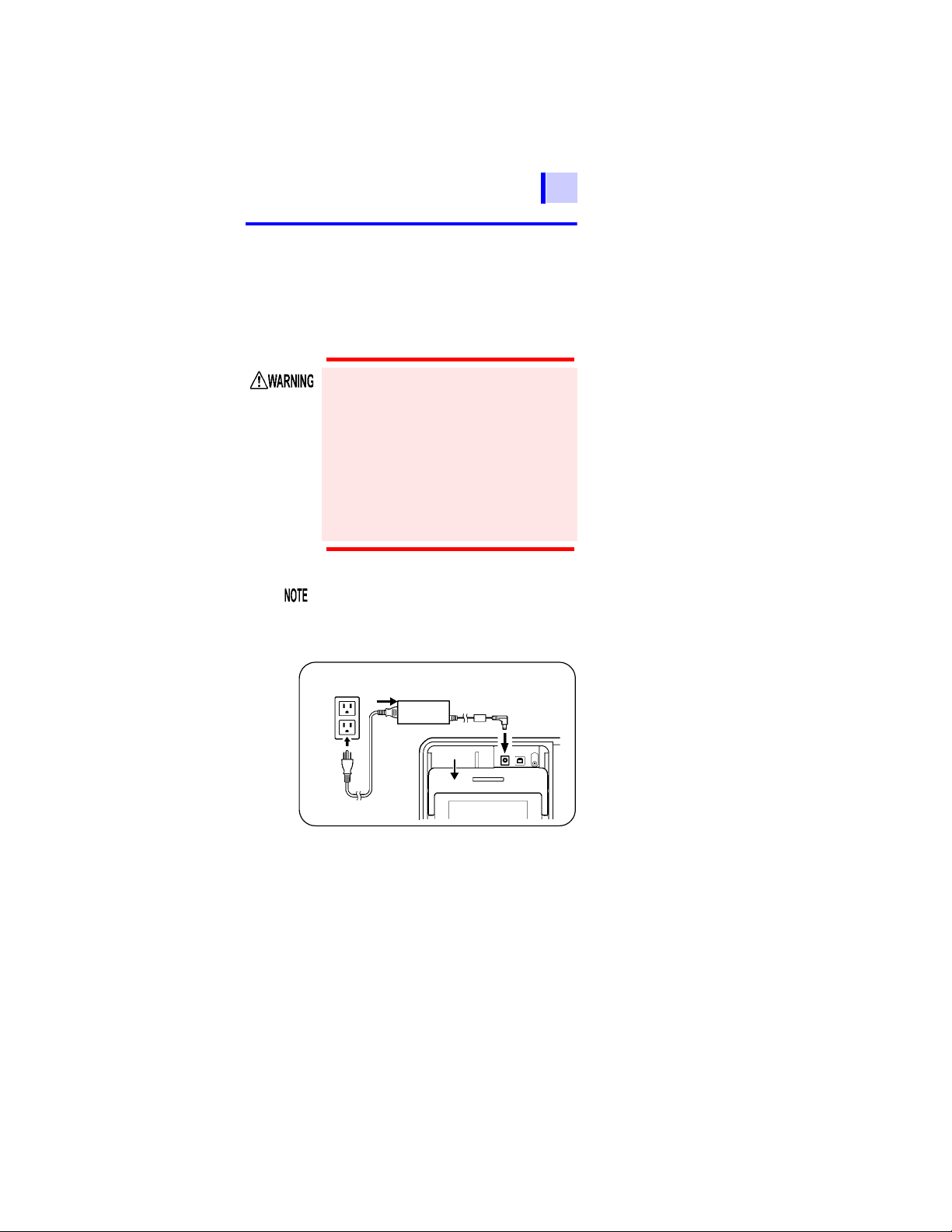
46
2.1 Supplying Power
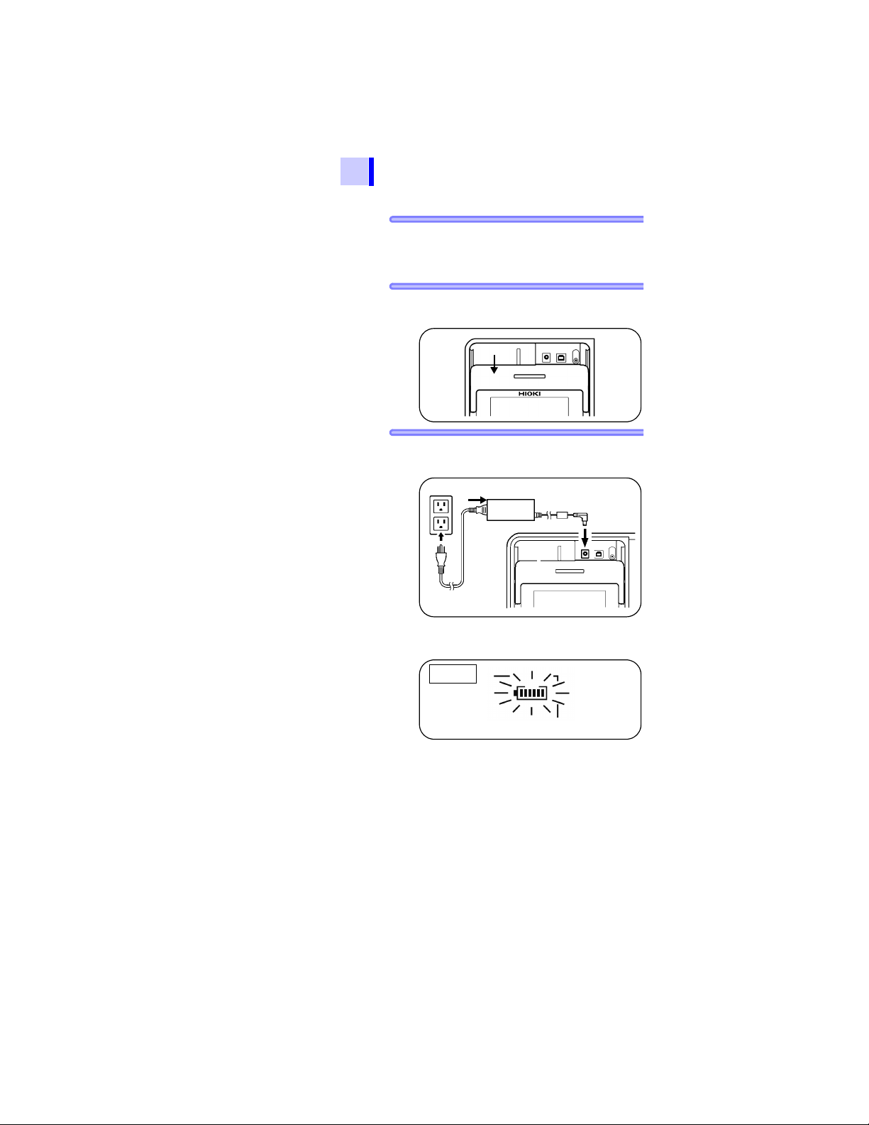
1. Insert the power cord into the AC
adapter.
2. Move the shutter of the instrument to
reveal the AC adapter terminal.
3. Insert the output cable of the AC adapter
into the AC adapter terminal.
4. Make sure that the commercial power
source voltage matches the rated supply
voltage of the AC adapter. Insert the
plug into the AC outlet.
When the AC adapter is connected to the instrument,
power is supplied from the AC adapter.
When both the battery and the AC adapter are connected to the instrument, the battery is not used.
If the battery pack is installed, when the AC adapter is
connected to the instrument, power of the instrument is
automatically turned on and charging of the battery pack
begins.
Find Quality Products Online at: sales@GlobalTestSupply.com
www.GlobalTestSupply.com

2.1 Supplying Power
47
2.1.4
The 9459 BATTERY PACK can be charged while installed
in the instrument, using the optional AC adapter.
Short charge time: Approx. 3 hours (at 23°C room temperature)
Charging the Battery Pack
• Carry out battery charging at an ambient
temperature between 0°C and 40°C.
However, the ambient temperature may
influence the charging efficiency. Outside
this range, not only is the charging capacity
reduced, but also there is a possibility of
reduced performance or electrolyte leakage.
• The battery pack cannot be charged when
test leads are connected to the
instrument.
• The battery pack will be charged regardless
of the battery selector switch position.
• Communication with a PC and temperature
measurement are available during charging.
But, insulation resistance measurement and
voltage measurement are not available.
• Only use the specified battery charger.
• Do not recharge a fully-charged battery
pack. If the battery pack is over-charged,
a deterioration in performance or battery
fluid leakage may result.
• During rapid charging, if the power supply
is suspended approximately for more than
100 msec, the battery status indicator
may show full charge even though it is
not. In that case, disconnect and then
connect AC adapter before starting to
charge again.
1
2
3
4
5
6
7
8
9
10
11
付録
索引
Find Quality Products Online at: sales@GlobalTestSupply.com
www.GlobalTestSupply.com
48
Move the shutter.
1
2
3
Battery status indicator
Charging
2.1 Supplying Power
Procedure
1. Install the battery pack.
See 2.1.2 "Installing the Battery Pack
(Rechargeable nickel-hydrogen battery)" (page
39).
2. Move the shutter to reveal the AC
adapter terminal.
3. Connect the AC adapter to the AC
adapter terminal.
Rapid charging begins. During rapid charging, the battery status indicator blinks.
See 2.1.3 "Connecting the AC Adapter" (page
45).
Find Quality Products Online at: sales@GlobalTestSupply.com
www.GlobalTestSupply.com

2.1 Supplying Power
49
If the AC adapter is connected to the
instrument when the instrument is off,
the instrument is automatically turned on
and rapid charging begins.
1
4. When rapid charging is completed, the
battery status indictor changes from
blinking to continuously lit. After rapid
charging finishes, the battery is tricklecharged (maintained in a fully-charged
state).
2
3
4
5
6
7
8
9
10
11
付録
索引
Find Quality Products Online at: sales@GlobalTestSupply.com
www.GlobalTestSupply.com
50
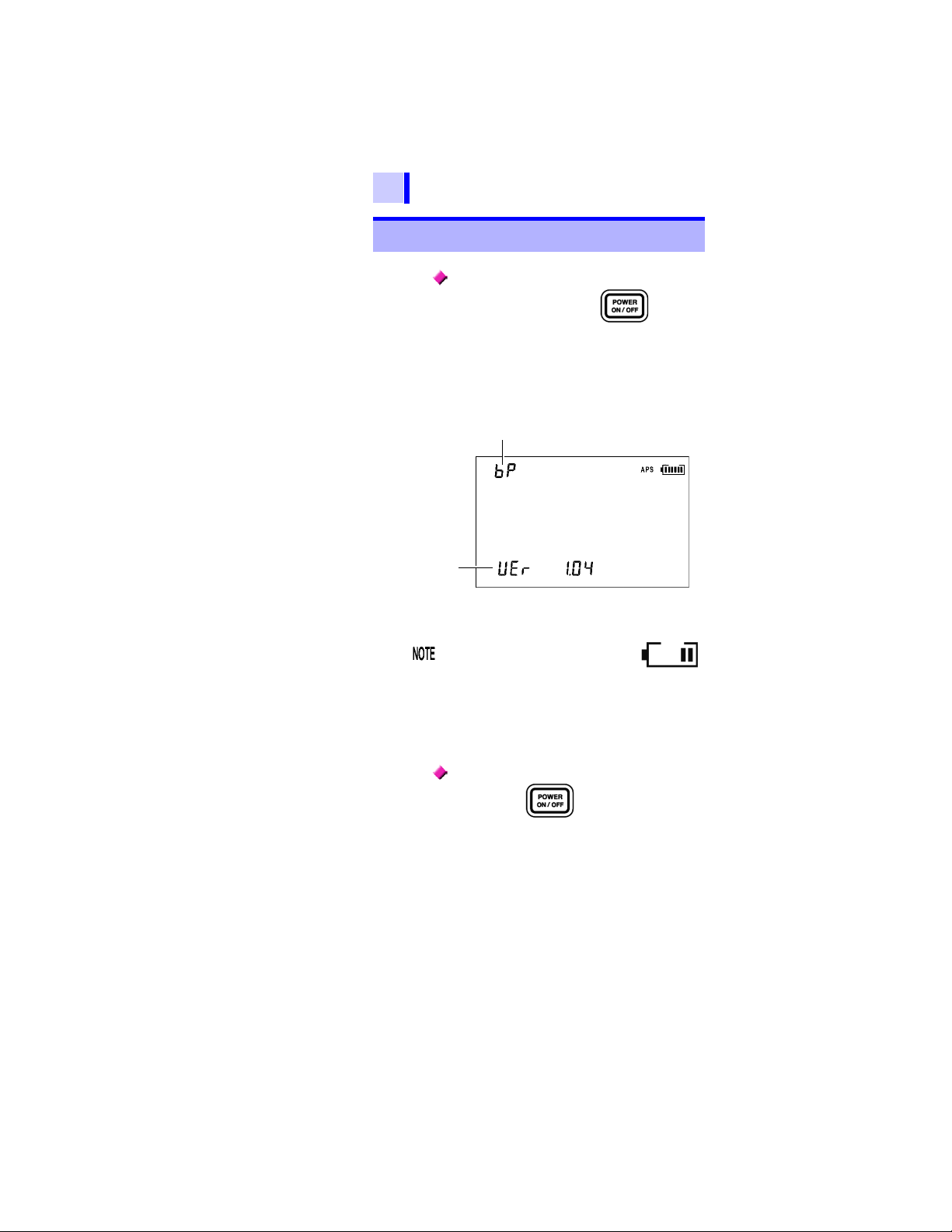
Indicates the position of the battery selector switch.
bP: Using the Model 9459 BATTERY PACK
Lr6: Using the LR6 alkaline batteries
Version
2.2 Turning Power On and Off
2.2 Turning Power On and Off
Turning power On
Press and hold the key for
around one second.
After all the screen indications light, the
version and the position of the battery
selector switch appear and then the
instrument enters the standby state.
The instrument recalls the settings that
were present before power was last turned
off.
When the battery status indicator
is low, re place th e battery.
See 2.1.1 "Installing or Replacing the Battery"
(page 36).
If the batteries or the battery pack is running
LObAt] is indicated. The instrument
low, [
turns off if use is continued.
Turing power off
Press the key.
The screen is switched off and power is
turned off.
Find Quality Products Online at: sales@GlobalTestSupply.com
www.GlobalTestSupply.com

2.2 Turning Power On and Off
2.2.1 Auto Power Off
51
• Power is automatically turned off around
10 minutes after the last operation. This
function, however, is not available during
insulation resistance measurement.
•[
APS] will start blinking around 30 sec-
onds before power is turned off.
• Auto power off is re-enabled upon turning
power on again. ([
• When the AC adapter is connected to the
instrument, auto power off is disabled.
• When the timer is set or when the instru-
ment is in the step voltage test mode,
auto power off is disabled.
Canceling Auto Power Off
Turn on power while holding down the
key.
APS] lights up.)
1
2
3
4
5
6
7
8
9
10
11
付録
索引
Find Quality Products Online at: sales@GlobalTestSupply.com
www.GlobalTestSupply.com
52
2.3 Setting and Checking Date and Time
2.3 Setting and Checking Date
and Time
Set the time and date before use of the instrument. Use the
Gregorian calendar.
2.3.1 Setting Date and Time
Procedure
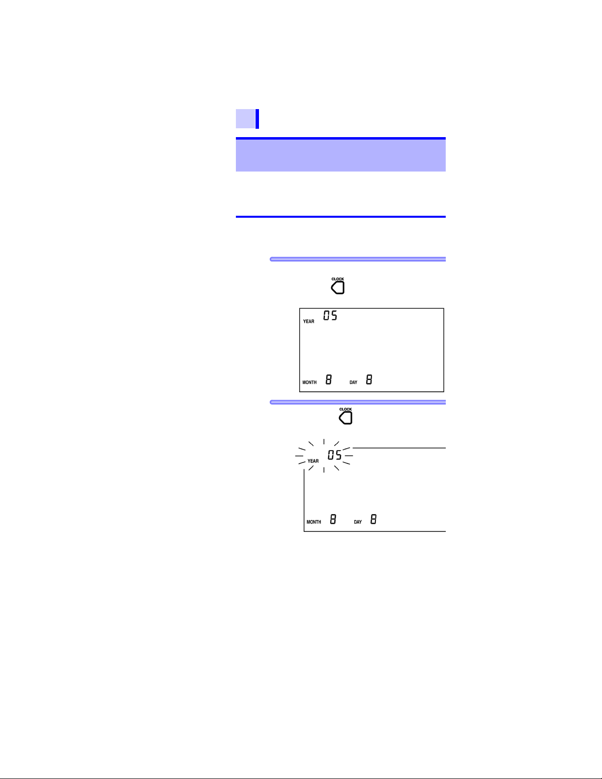
1.
When the instrument is in a standby state,
press the key. Year, month, and day
appear.
2. Hold down key for more than one
second. The Year starts blinking.
Find Quality Products Online at: sales@GlobalTestSupply.com
www.GlobalTestSupply.com

2.3 Setting and Checking Date and Time
3. Pressing moves the blinking
cursor. Place the cursor at the digit,
value, etc., you wish to change.
Year, month, day, hour, and minutes can
be changed.
The year-month-day screen and the hourminute-second screen are switched to and
from each other in the procedure below.
53
YEAR] is
DAY] is blink-
Year-month-day
Hour-minute-
second
• When year [
blinking, press the
key.
• When day [
ing, press the key.
1
2
3
4
5
h] is blink-
min] is
Hour-minute-
second
Year-month-day
• When hour [
ing, press the key.
• When minute [
blinking, press the
key.
4. Press to change the number.
Hold down for fast increase/decrease.
5. The entry is confirmed by pressing the
key, after which the display returns
to the standby screen.
The clock starts to run from zero seconds
as soon as key is pressed.
6
7
8
9
10
11
付録
索引
Find Quality Products Online at: sales@GlobalTestSupply.com
www.GlobalTestSupply.com

54
2.3 Setting and Checking Date and Time
Date and time can be set on a PC.
• The date and time can be set on a PC
using the data analysis software for
model 3455.
• The data analysis software for model
3455 must be installed on the PC.
Details See 6.4 "Communicating with PC"
(page 136).
Find Quality Products Online at: sales@GlobalTestSupply.com
www.GlobalTestSupply.com

2.3 Setting and Checking Date and Time
2.3.2 Checking Date and Time
55
Procedure
1. When the instrument is in the standby
state, press the key.
Year, month, and day appear.
2. Press the key.
Hours, minutes, and seconds appear.
1
2
3
4
5
6
7
8
9
10
3. Pressing key returns to the st and by
screen.
Find Quality Products Online at: sales@GlobalTestSupply.com
www.GlobalTestSupply.com
11
付録
索引

56
2.4 Connecting Test Lead
2.4 Connecting Test Lead
• To avoid electrical accidents, remove
power from the circuit before connecting the test leads.
• To avoid electric shock, never use the
instrument if the shutter is broken.
Only use Hioki-specified test leads with
the instrument. Safe measurement is not
possible with other cords.
Test leads cannot be connected to the
instrument if the AC adapter, a temperature
sensor, or USB cable is connected.
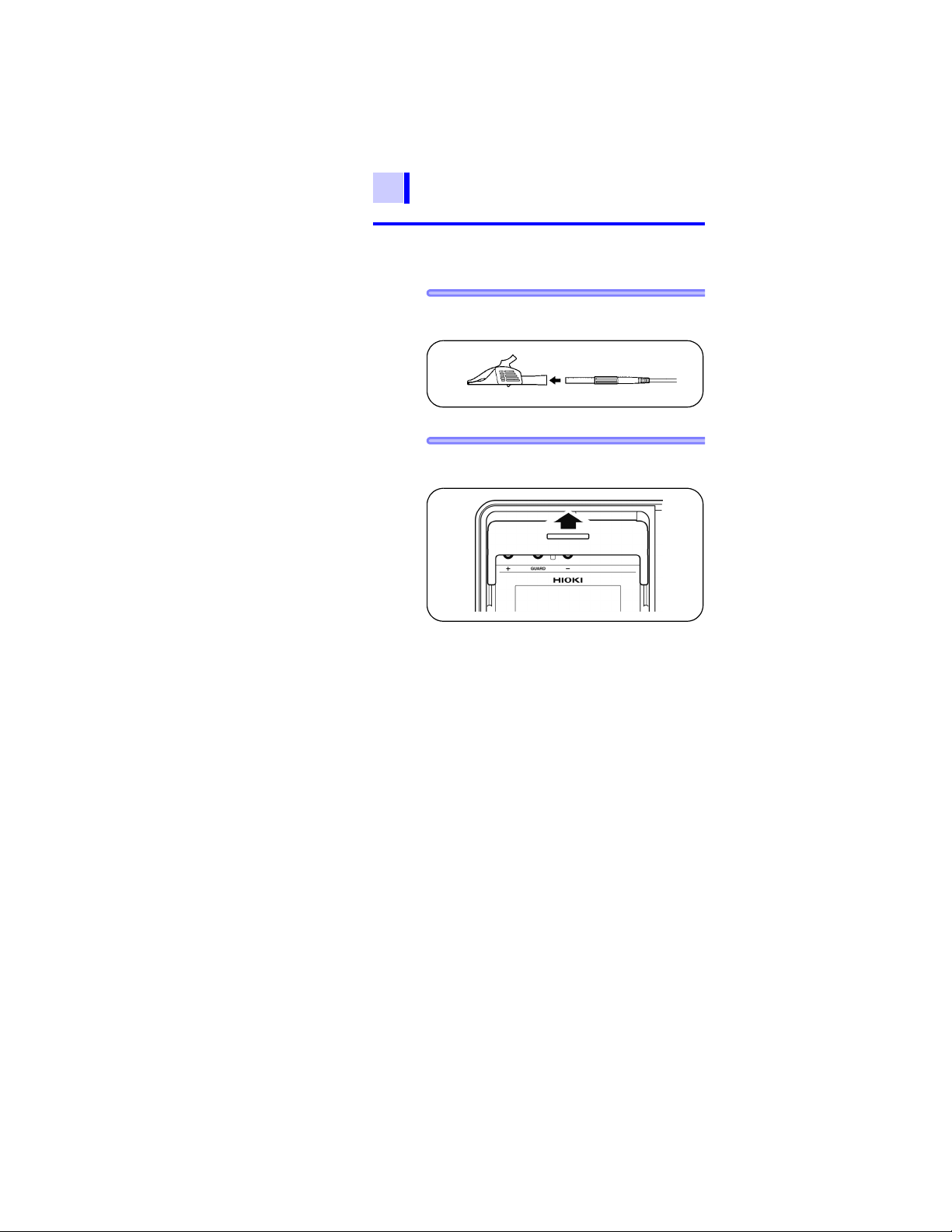
Procedure
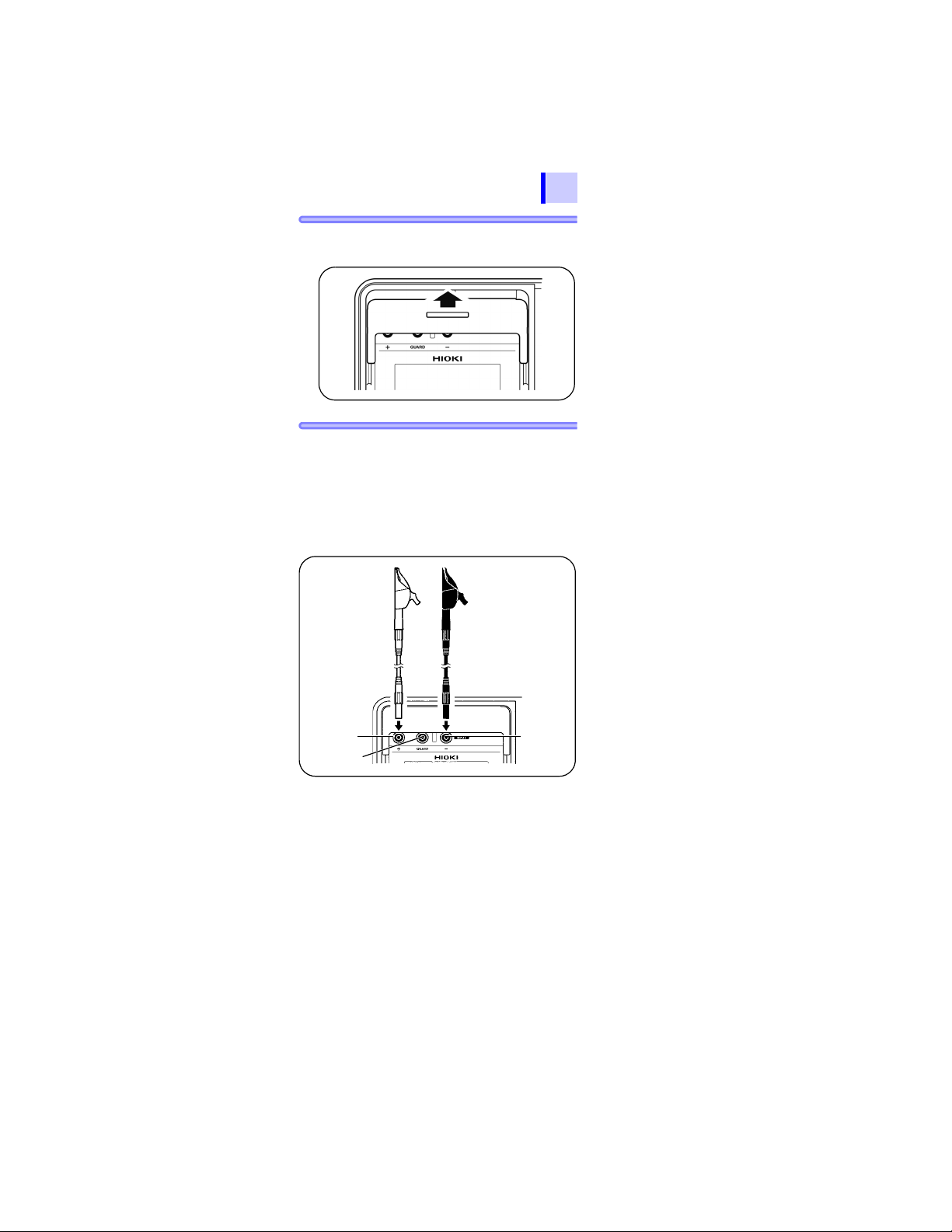
1. Connect the alligator clip to the end of
each test lead. Insert it fully.
Find Quality Products Online at: sales@GlobalTestSupply.com
www.GlobalTestSupply.com
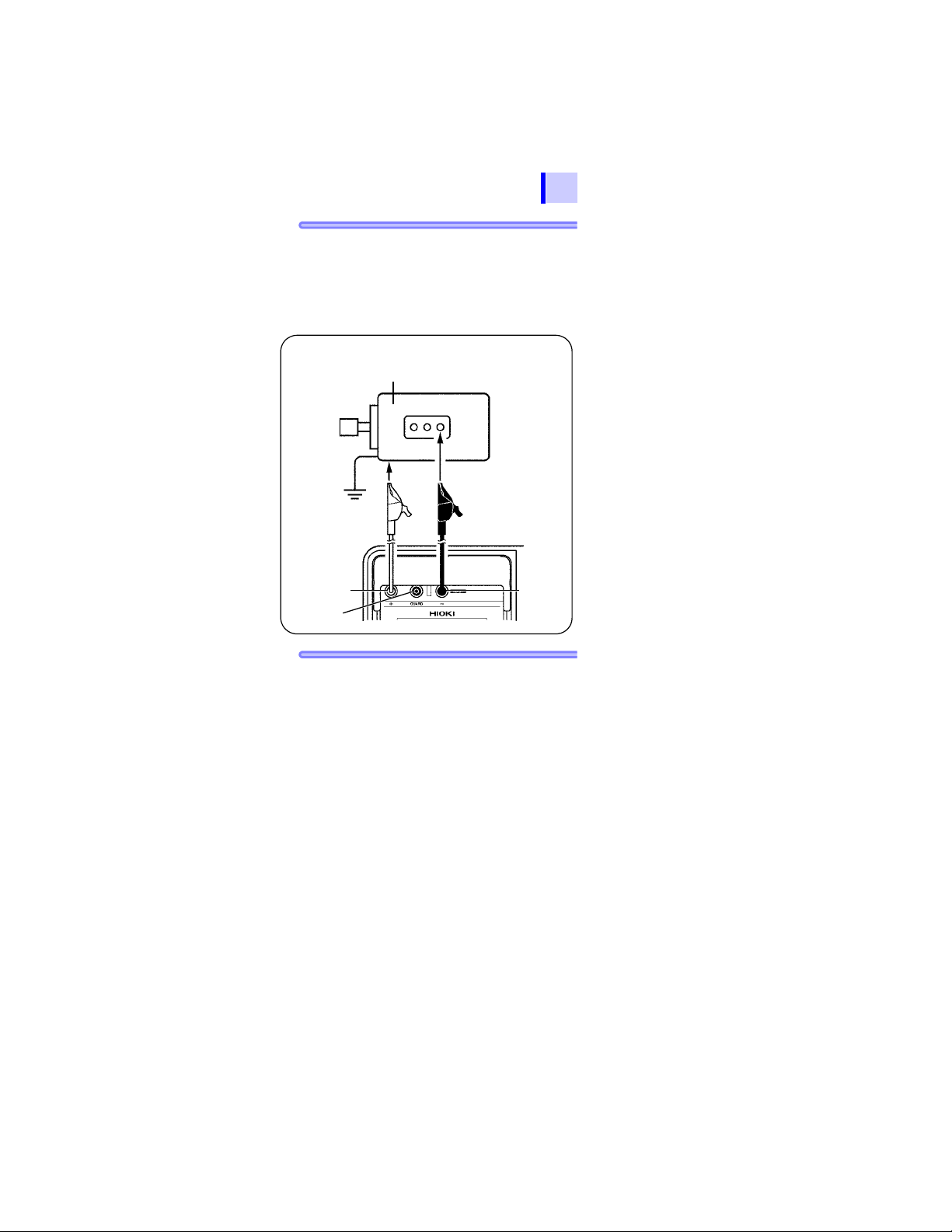
2.4 Connecting Test Lead
+ terminal
- terminal
GUARD
terminal
Test lead (Red) Test lead (Black)
57
2. Move the shutter to reveal the + and -
terminals.
3. Connect the red test lead to the + terminal
and the black test lead to the - te rmina l.
For insulation resistance measurement,
connect the blue test lead to the GUARD
terminal if necessary.
Check that the test leads are fully
inserted.
1
2
3
4
5
6
7
8
GUARD terminal See 3.2.7 "Use of GUARD
Terminal" (page 77).
9
10
11
付録
索引
Find Quality Products Online at: sales@GlobalTestSupply.com
www.GlobalTestSupply.com

58
Move the shutter.
Temperature
sensor terminal
2.5 Connecting Temperature Sensor
2.5 Connecting Temperature
Sensor
Temperature sensors may be damaged by
high voltage or static electricity. Do not
expose the temperature sensor to exce ssive
impact, or allow the cable to be bent, since
malfunction or faulty connection may result.
Temperature sensors cannot be used
simultaneously with test leads.
Procedure
1. Move the shutter to reveal the temperature
sensor terminal.
2. Connect the temperature sensor to the
temperature sensor terminal.
Temperature measurement begins automatically.
Find Quality Products Online at: sales@GlobalTestSupply.com
www.GlobalTestSupply.com
3.1 Pre-Operation Inspection
Measurement 3
59
1
3.1 Pre-Operation Inspection
Before using the instrument, verify that it operates normally to ensure that no damage
occurred during storage or shipping. If you find
any damage, contact your authorized Hioki distributor or reseller.
Before using the instrument, make sure
that the insulation on the test leads and
cables is undamaged and that no bare
conductors are improperly exposed.
Using the product in such conditions
could cause an electric shock, so contact
your authorized Hioki distributor or
reseller for replacements.
Make sure the terminals are clean and dry.
Wipe with a dry cloth to remove any
moisture, since measurement errors may
result if moisture is present.
See 8.2 "Cleaning" (page 158).
Checking for damage
Confirm that the instrument chassis, shutter, test leads, and clips are not damaged.
Do not used if damaged.
Checking test voltage and resistance
reading
Equipment
• 20 M resistor that provides a voltage of
5 kV
• High-voltage meter with an input resistance of 1,000 M or more, and capable
of measuring up to 5.5 kV DC
2
3
4
5
6
7
8
9
10
11
付録
索引
Find Quality Products Online at: sales@GlobalTestSupply.com
www.GlobalTestSupply.com

60
3.1 Pre-Operation Inspection
Inspection
Procedure
1. Clip the resistor with the red and black
test leads connected to the instrument.
2. Also, clip the resistor with the test lead of
the high-voltage meter.
3. Set the test voltage of the instrument to
[5.00 kV].
See 3.2Measuring Insulation Resistance, Proce-
4. Hold down key for more than
one second to start insulation resistance
measurement.
5.
Check to see if the reading of the high-voltage meter is somewhere between 5 kV and
5.5 kV .
dure 5. (page 66) to (p age 66).
6. Check to see if the voltage reading of the
instrument is somewhere between 5 kV
and 5.5 kV.
Find Quality Products Online at: sales@GlobalTestSupply.com
www.GlobalTestSupply.com
3.1 Pre-Operation Inspection
Insulation resistance
Voltage
61
7. Check to see if the insulation resistance
reading of the instrument is 20 M.
1
2
3
4
8. Stop insulation resist ance m easurement.
See 3.2.2 "Ending Measurement" (page 70).
9. Short-circuit the tips of the clips of the
red and black test leads of the instrument.
10. Press the key to see if the test volt-
age setting is [5.00 kV].
11. Hold down the key for more than
one second to start insulation resistance
measurement.
12. Check to see if the insulation resistance
reading of the instrument is 0.00 M.
If a problem exists, discontinue use of
the instrument.
5
6
7
8
9
10
11
付録
索引
Find Quality Products Online at: sales@GlobalTestSupply.com
www.GlobalTestSupply.com
62
Shutter
3.2 Measuring Insulation Resistance
3.2 Measuring Insulation
Resistance
Observe the following to avoid electric
shock and short circuits.
A. Do not use the
instrument if the
shutter is broken.
B. Check T able 1
before connecting test leads to the
instrument.
C.
Check to see if the object under test is
not live or electrically charged using a
high-voltage detector or other similar
instrument, before connecting test
leads to it.
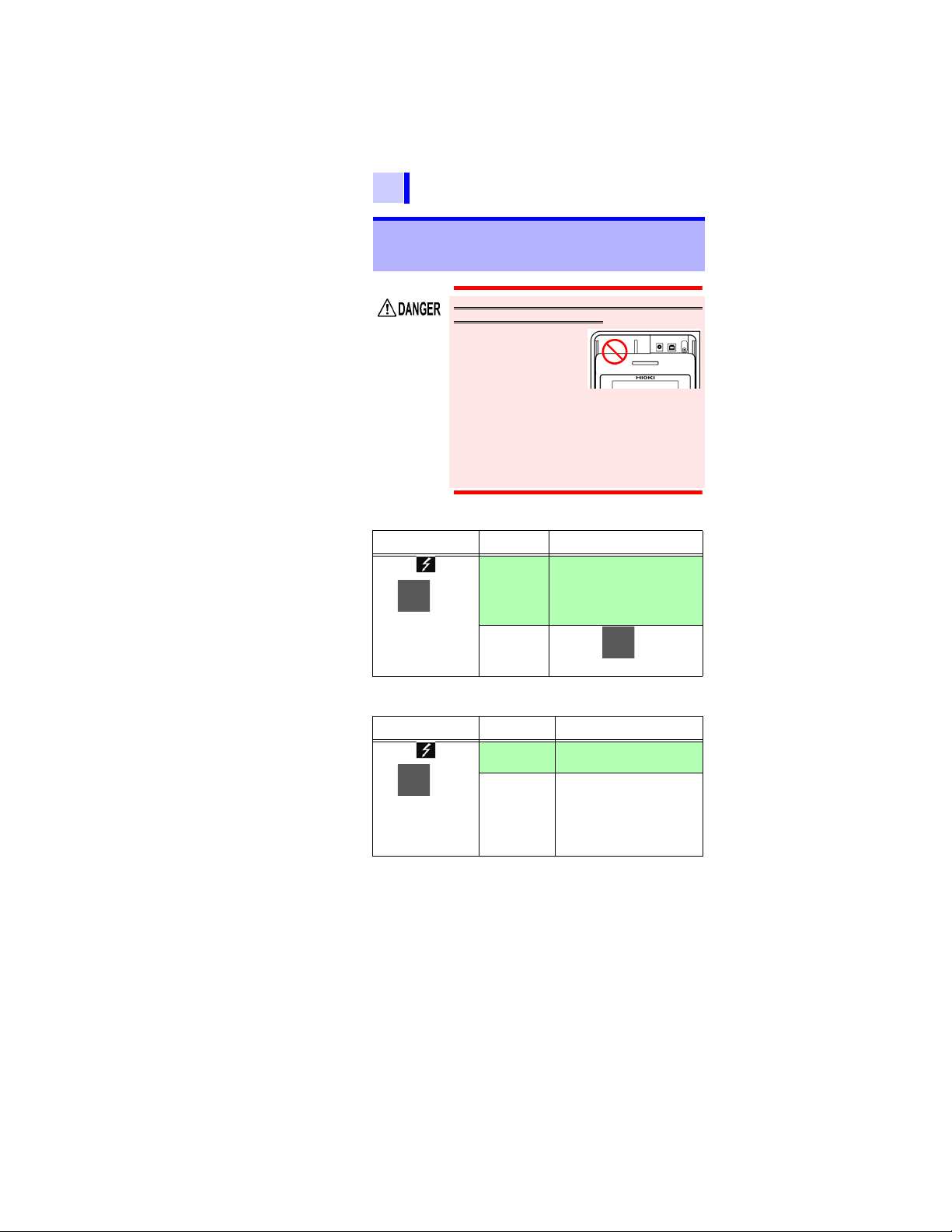
Table 1
Check item Result Action
Are the mark
and key lamp
off?
Off Connect test leads to the in-
strument and check C. above.
If safe to proceed, connect the
test leads to the object under
test. Go to Table 2.
Blinking Press the key to stop
voltage generation.
Table 2
Check item Result Action
Are the mark
and key lamp
blinking?
Not blinking Measurement may be com-
menced
Blinking Immediately disconnect the
test leads from the object under test and turn off power to
the object or discharge the
electric charge using a discharge rod.
Find Quality Products Online at: sales@GlobalTestSupply.com
www.GlobalTestSupply.com
3.2 Measuring Insulation Resistance
63
• When measuring insulation resistance,
dangerous voltage is applied to the
measurement terminals. To avoid electric shock, do not touch the terminals
and test leads.
• Do not touch the object under test or
disconnect the test leads after measurement has been completed until the automatic discharge function is completed.
Electric shock may result due to high
voltage and stored charge.
See 3.2.4 "Automatic Discharge Function" (page
73).
• Power of the instrument may be turned
off during measurement even if the
key is not pressed, for instance,
due to battery consumption. In such
case, the automatic discharge function
may not operate. Discharge the object
under test using a discharge rod for
high voltage.
1
2
3
4
5
6
• To avoid damage to objects under test, be
sure to check the test voltage before
starting measurement.
• When repeating measurement, press the
key before next measurement to check
the test voltage.
• To avoid damage to the instrument during
discharge, do not measure the insulation
resistance between the terminals of
capacitors (with a capacit anc e of over 4 F).
• To avoid damage to the instrument, do not
short-circuit the tips of the clips of the red
test lead (+ terminal) and the blue test lead
(GUARD terminal).
7
8
9
10
11
付録
索引
Find Quality Products Online at: sales@GlobalTestSupply.com
www.GlobalTestSupply.com
64
3.2 Measuring Insulation Resistance
3.2.1 Starting Measurement
Procedure
1. Connect the alligator clip to the end of
each test lead. Insert it fully.
2. Move the shutter to reveal the + and -
terminals.
Find Quality Products Online at: sales@GlobalTestSupply.com
www.GlobalTestSupply.com
3.2 Measuring Insulation Resistance
GUARD
terminal
Warning: Confirm that the power supply to the
object under test has been turned off.
Object to be measured (Ex.: Motor)
+ terminal
- terminal
Test lead (Red)
Attach to a metal
chassis or a ground
terminal.
Test lead (Black)
Attach to a metal part
of the power supply
terminal.
65
3. Connect the red test lead to the + terminal
and the black test lead to the - te rmina l.
Connect the blue test lead to the
GUARD terminal if necessary.
Fully insert the test leads.
See 3.2.7 "Use of GUARD Terminal" (page 77 ).
1
2
3
4
5
6
7
8
4. Clip the alligator clip at the end of each
test lead to the object under test.
9
10
11
付録
索引
Find Quality Products Online at: sales@GlobalTestSupply.com
www.GlobalTestSupply.com
66
3.2 Measuring Insulation Resistance
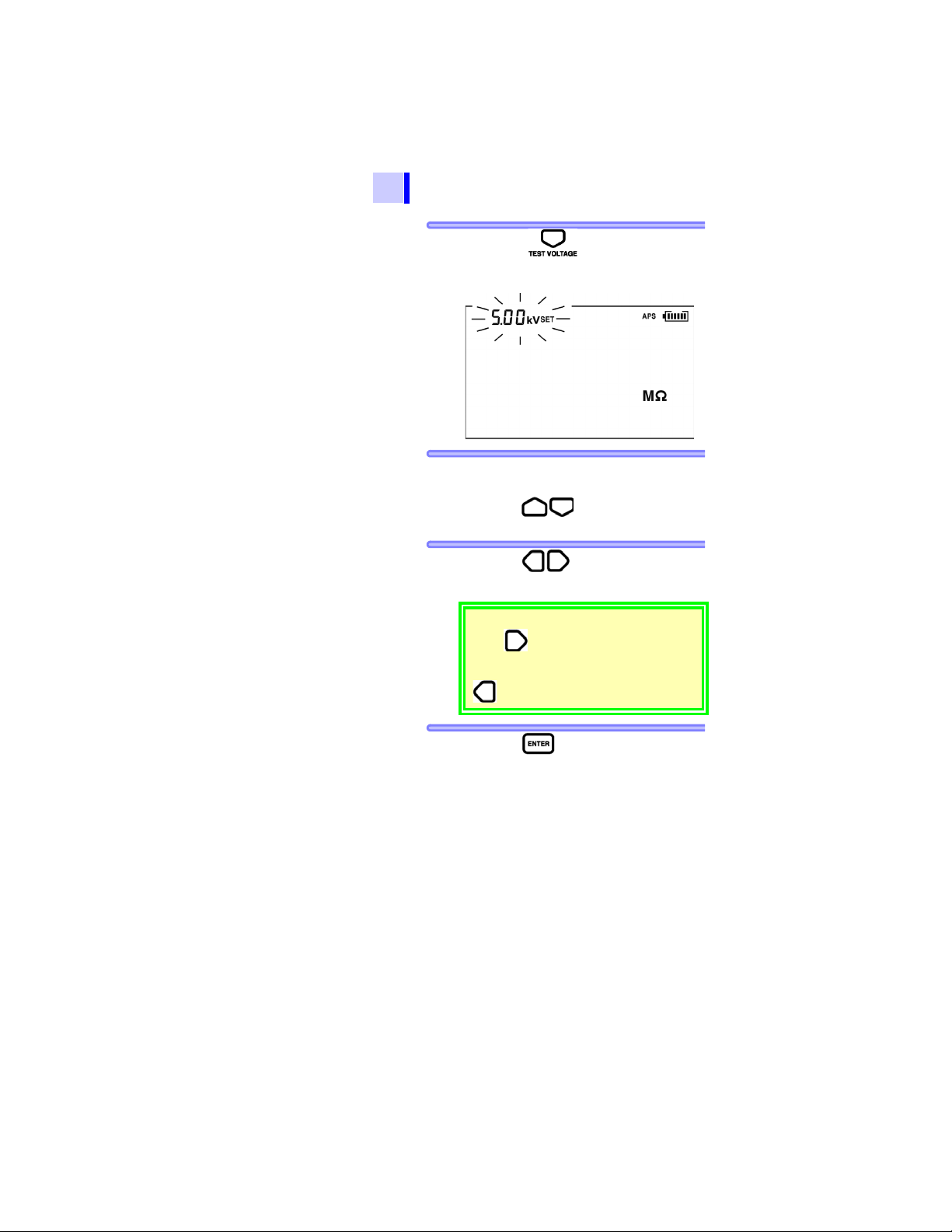
5. Press the key, after which the
voltage display starts blinking.
6. The test voltage is chosen from 250 V,
500 V, 1.00 kV, 2.50 kV, and 5.00 kV
using the keys.
7. Pressing keys, you can make
fine adjustment of the test voltage setting.
For step voltage testing, hold down
the
STEP]. For non-stepped insulation
[
resistance measurement, press the
key and choose a voltage.
key, which will display
8.
Press the key to set the test voltage.
The voltage indication will change from
blinking to continuous.
This test voltage is now set.
Find Quality Products Online at: sales@GlobalTestSupply.com
www.GlobalTestSupply.com
3.2 Measuring Insulation Resistance
Actual output
voltage
Blinking
>blinks if the
input exceeds the
measurement
range.
Elapsed time Insulation resistance
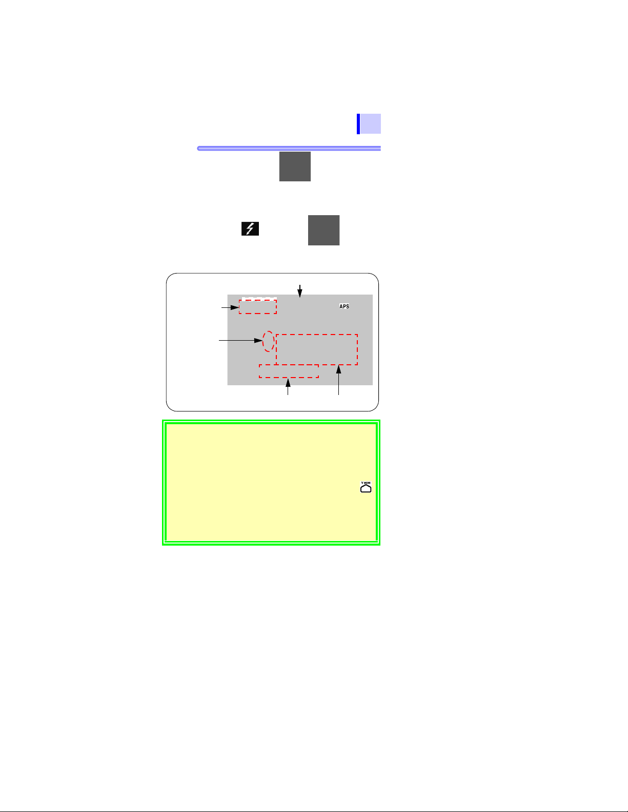
9. Hold down the key for more than
67
one second.
A voltage is generated and measurement
begins.
The mark and key lamp
starts blinking.
If > blinks, the input value is out of measurement range.
Example: > 10.0 T means "larger than 10.0 T."
• During mea suremen t, [
tion field and the indication changes from the se t voltage to
the actual output voltage. A voltage approximat ely 5% higher
than the set level is output.
• To view the set voltage during measurement, press the
key. The set voltage is displayed for approximately 2 seconds.
• During me asurement, if the output voltage is lower tha n the
set level, the voltage indication blinks.
• Under the resistance indication appears time elapsed from the
start of measurement.
SET] is turned off in the voltage indica-
1
2
3
4
5
6
7
8
9
10
11
付録
索引
Find Quality Products Online at: sales@GlobalTestSupply.com
www.GlobalTestSupply.com
68
3.2 Measuring Insulation Resistance
10. Read the indication.
• If the indication is unstable, press the
surements is shown.
See "Average function" (page 69).
• Resistance indication is switched to
leakage current indication by pressing
the key.
See 3.2.5 "Switching to Leakage Current
Indication" (page 74).
• When the timer has been set, remaining time is displayed.
See 4.1 "Using Timer" (page 85).
Do not allow test leads to contact each other
or place objects on test leads, to avoid measurement errors and malfunctions.
• Be sure to clean test leads after use. If test
leads are soiled, they may deteriorate.
• Insulation resistance is unstable. The
indication may not stabilize with some
objects.
• Due to factors such as capacitance of
objects under test, resistance values may
start low, then rise grad ually and settle out.
• During measurement, if the resistance of
the object suddenly drops or if the test
lead tips are short-circuited, the
instrument stops voltage generation as a
safety measure. (This applies to a test
voltage of 1.1 kV or more.)
key. The average of the mea-
Find Quality Products Online at: sales@GlobalTestSupply.com
www.GlobalTestSupply.com

3.2 Measuring Insulation Resistance
69
The state not to be started the measurement
When the display reflects the following
state, insulation resistance measurement
cannot be started.
• The setting value is blinking to indicate
that the instrument being set up
• The mark is blinking
•While [TC] is lit, the actual measurement
temperature is shown as [- - -]
• An error massage is displayed
1
2
3
Average function
If the indication is unstable, the average of
the measurement is shown.
Pressing the key toggles [AVE] on/
off.
While [AVE] is on, display update interval is
four seconds, normally.
But in the following case, the interval is one
second even if [AVE] is on.
• During 15 seconds after the measurement started
• During 5 to 10 seconds after the measurement range changed
4
5
6
7
8
9
10
11
付録
索引
Find Quality Products Online at: sales@GlobalTestSupply.com
www.GlobalTestSupply.com

70
3.2 Measuring Insulation Resistance
3.2.2 Ending Measurement
Procedure
1. Press the key with the test leads
connected to the object under test.
The last measurement is held.
( lights up.)
2. Immediately after measurement has
been completed, the discharge circuit in
the instrument automatically discharges
the electric charge remaining in the
object under test.
See 3.2.4 "Automatic Discharge Function" (page
73).
3. During discharge, the mark and
key lamp blinks.
The voltage indication shows the progress
of discharge.
Find Quality Products Online at: sales@GlobalTestSupply.com
www.GlobalTestSupply.com

3.2 Measuring Insulation Resistance
LastElapsed time of the
Actual output
voltage
(last measurement)
end of measurement measurement value
Check
71
4. When the voltage falls to about 10 V, the
instrument stops discharging and the
mark and key lamp are turned off.
• If the key is pressed during
measurement, automatic discharge is
performed before power is turned off.
• If the battery runs low during measurement, the instrument automatically
stops measurement. Automatic discharge is performed and then [LObAt]
appears on the screen.
1
2
3
4
5
6
7
8
9
5. To restart measurement, press the
key to check the set test voltage before
resuming measurement.
10
11
付録
索引
Find Quality Products Online at: sales@GlobalTestSupply.com
www.GlobalTestSupply.com

72
Checking Held Data
Insulation
resistance
Leakage
current
DAR 1 min/ 30 s
PI (10/1 min.)
DAR 1 min/15 s
Test voltage
(setting)
Actual output
voltage
Deleting Held Data
3.2 Measuring Insulation Resistance
3.2.3 Checking and Deleting Held Data
The following data are held and displayed after insulation
resistance measurement has been completed.
• Insulation resistance (digital value and bar graph)
• Test voltage
• Actual output voltage
• Leakage current
• Elapsed time
•DAR
•PI
Some data may not be displayed. Press the keys shown in
the table below to switch the indication.
Data indications to be switched Keys used
key
key
Elapsed time Temperature/humidity
(When the data are held)
key
The held data are cleared when power is
turned off. To save the data, use the
memory function.
See 5 "Recording Measurement Data (Memory
Function)" (page 105) .
To clear the data, press the key for more than one second.
Temperature/humidity data will not be cleared.
Find Quality Products Online at: sales@GlobalTestSupply.com
www.GlobalTestSupply.com

3.2 Measuring Insulation Resistance
3.2.4 Automatic Discharge Function
73
• When insulation resistance with a capacitance component
is measured, this component remains charged with a
high-voltage equivalent to the test voltage, which is dangerous.
• This instrument automatically discharges remaining electric charge using the internal circuit after measurement.
• Make sure that the test leads are connected to the measured
object when pressing the key to stop measurement.
• Discharging stops when the residual voltage falls below 10
V . The discharge time var ies depe nding on the cap aci t ance.
After the voltage has been decreased by
the instrument’s automatic di scharge function, the voltage in the measurement area
may rise again due to the remaining charge
in the capacitor C
section 3.2.6. Take great care when touching the object under test.
A shown in the diagram in
1
2
3
4
5
6
7
8
9
10
11
付録
索引
Find Quality Products Online at: sales@GlobalTestSupply.com
www.GlobalTestSupply.com

74
During measurement
Blinking
Elapsed time
Actual output
voltage
The bar graph
shows the
resistance
measurement.
< blinks at
below 1 nA.
Current measurement
3.2 Measuring Insulation Resistance
3.2.5 Switching to Leakage Current Indication
Insulation resistance indication may be switched to leakage
current indication.
Before measuring insulation resistance
and after setting test voltage
( indicator is off.)
Every time the key is pressed, the
indication changes in the order: resistance
current PI resistance etc.
Measuring insulation resistance
Every time key is pressed, the indication changes in the order: resistance
current resistance current etc.
Find Quality Products Online at: sales@GlobalTestSupply.com
www.GlobalTestSupply.com
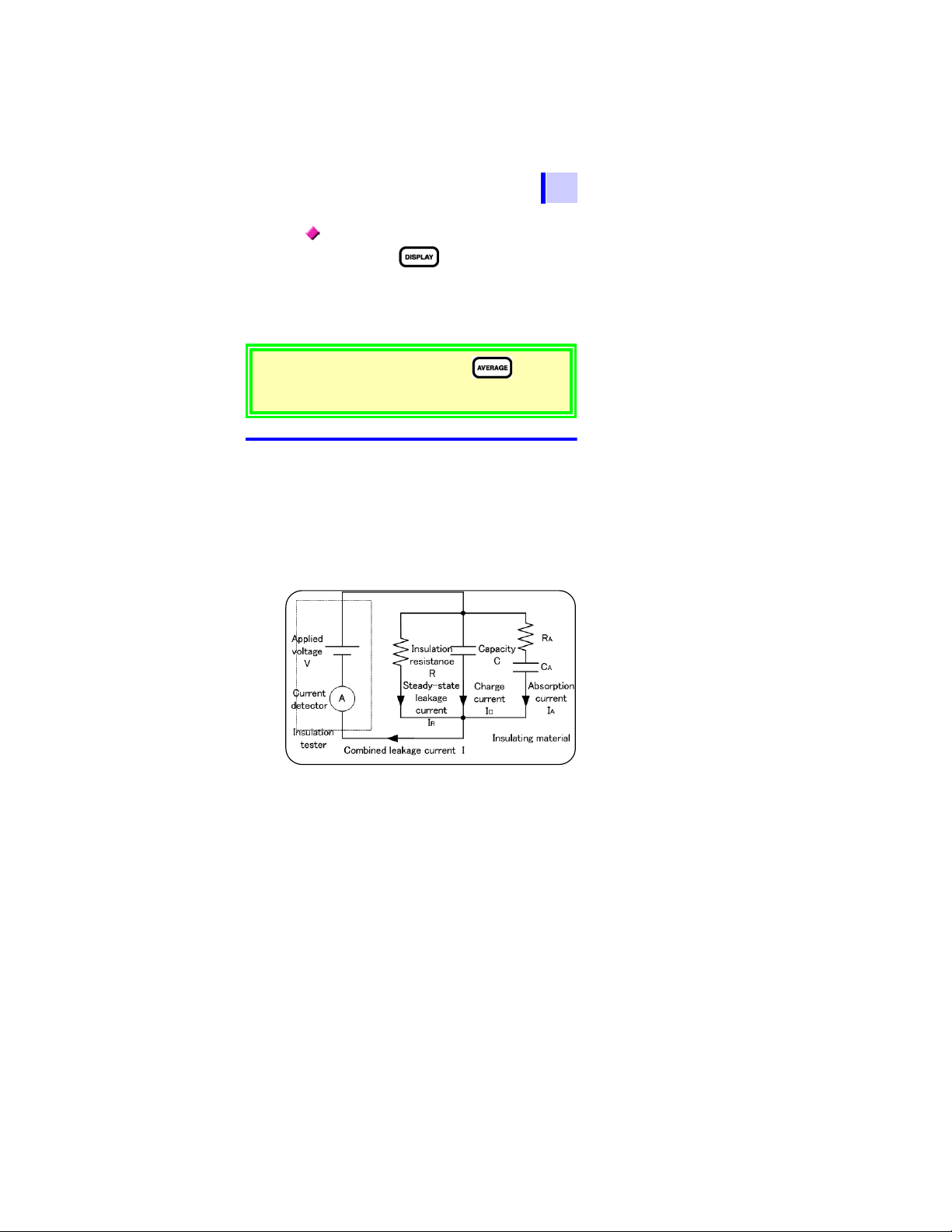
3.2 Measuring Insulation Resistance
75
Holding data after measurement
Every time key is pressed, the indication changes in the order: resistance
current DAR 1 min/15s DAR 1 min/30s
PI resistance current etc.
PI/DAR See 4.2 "Displaying PI and DAR"
(page 89).
1
2
If the indication is unstable, press the key. The
average of the measurements is shown.
[< 1.00 nA] means "below 1.00 nA."
3.2.6 Insulation Resistance Mea surement Basis
When a high DC voltage is applied to an object under test, a
leakage current flows.
The insulation resistance instrument measures the applied
voltage V and the combined leakage current I and then calculates the insulation resistance R.
Calculation formula R = V/I
C and IA gradually decrease after the volt-
I
age is applied.
3
4
5
6
7
8
9
10
11
付録
索引
Find Quality Products Online at: sales@GlobalTestSupply.com
www.GlobalTestSupply.com

76
3.2 Measuring Insulation Resistance
Reproducibility of insulation resistance
measurement
When measuring the same object repeatedly, the insulation resistance or leakage
current indications may differ. This is caused
by polarization*, which occurs when a voltage is applied to an insulating material.
An insulating material is represented by an
equivalent circuit as shown by the diagram
on the previous page.
Absorption current due to relatively slow
polarization is represented by I
in the diagram above. It takes time for the
polarization caused by the previous measurement disappear. Until it does, electric
charge remains in C
gram. The electric charge level in C
at the start of previous measurement and at
the start of next measurement and thus
absorption current I
combined leakage current and insulation
resistance vary from measurement to measurement. This will be become more apparent for higher insulation resistance values.
To ensure reproducibility of measurement,
leave a sufficient time interval between measurement sessions. Further, the ambient
temperature and humidity should not vary.
A, as shown
A as shown in the dia-
A differs
A differs, too. Further, the
*Polarization: the phenomenon in which positive
and negative charges on the atoms of
a material move in opposite directions causing a shift of the center
when an electric field is applied to the
material.
Find Quality Products Online at: sales@GlobalTestSupply.com
www.GlobalTestSupply.com
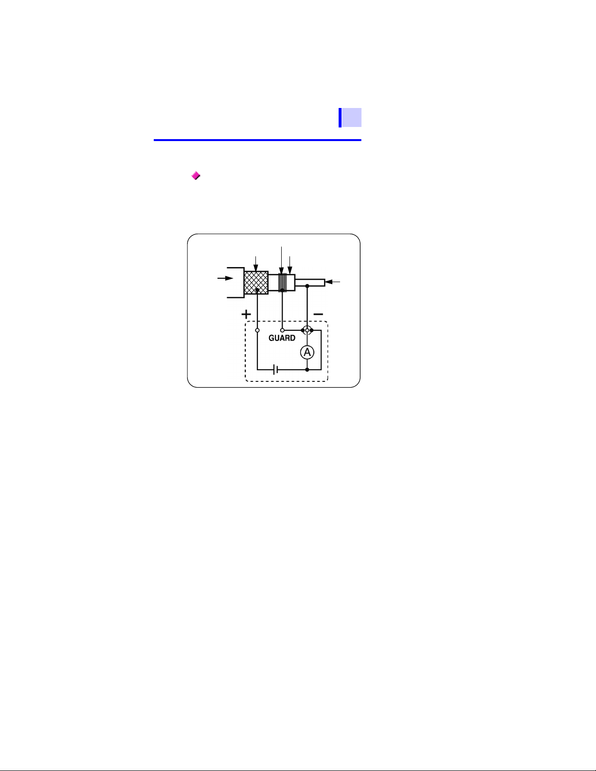
3.2 Measuring Insulation Resistance
Metallic shielding layer
Bare conductor
Insulating material
Cable
Core
Current
detector
Power supply
3.2.7 Use of GUARD Terminal
77
Measurement unaffected by surface
electrical resistance
A GUARD terminal is used to prevent the
surface electrical resistance of an insulating
material affecting measurement, enabling
correct measurement of the entire volume
resistivity of the material.
When testing the insulation of a cable, as
shown in the diagram above, wind a bare
conductor around the surface of the insulating material and connect the conductor to
the GUARD terminal. This prevents the
leakage current on the surface of the insulating material flowing into the current
detector, which enables the actual resistance of the entire volume of the insulating
material to be measured.
1
2
3
4
5
6
7
8
9
10
11
付録
索引
Find Quality Products Online at: sales@GlobalTestSupply.com
www.GlobalTestSupply.com
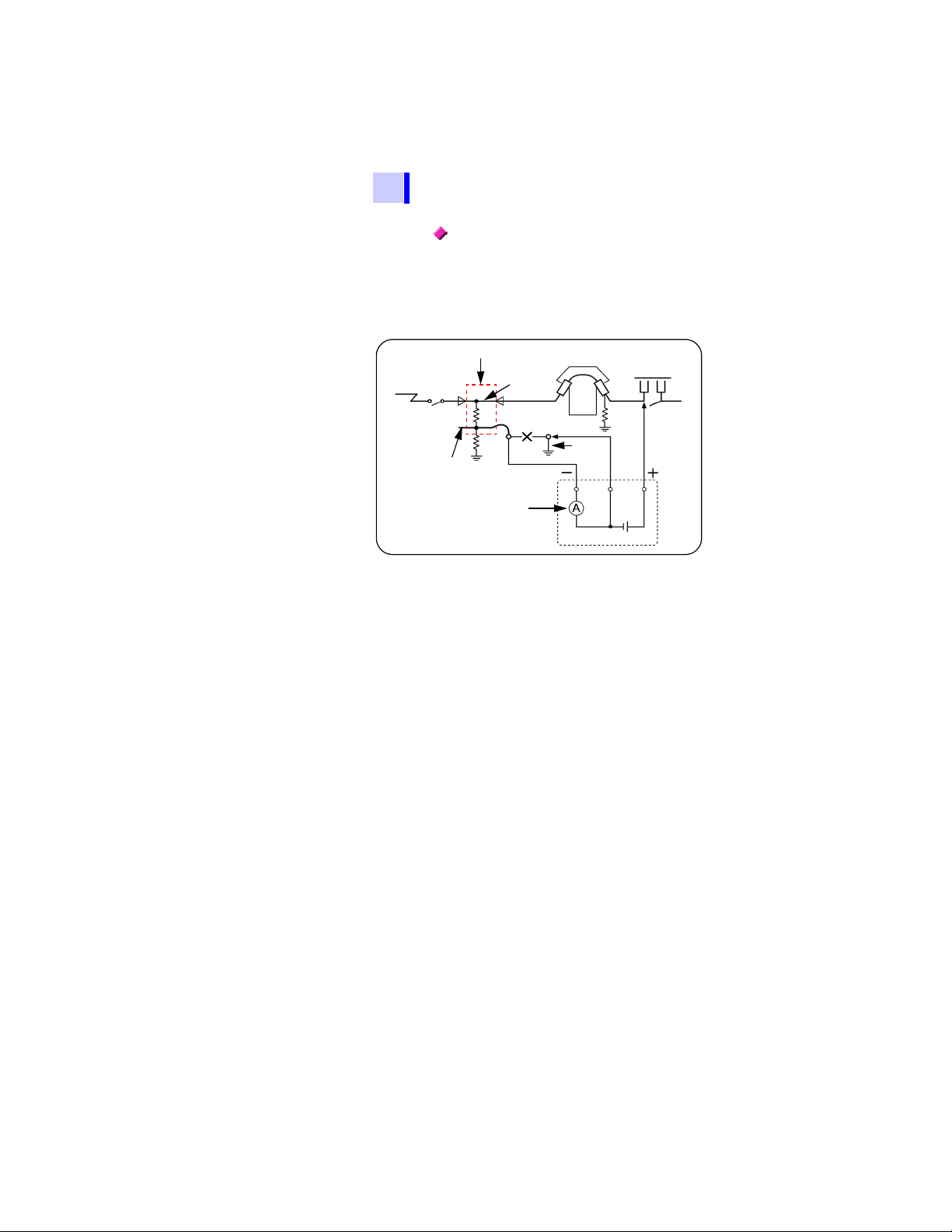
78
Meter transformer
Disconnector
Load
Core
R
n
Rc
Rs
N
Remove
Grounding
P
Power supply
wire
Cable
Power
supply
side
side
wire
Metallic shielding layer
of the cable
Current
detector
GUARD
3.2 Measuring Insulation Resistance
Measurement using G (GUARD)
terminal grounding
G terminal grounding is used for measuring
the insulation resistance between the core
and the metallic shielding layer of a highvoltage cable with the cable connected to
other high-voltage equipment. The diagram
below shows an example of measurement.
Rc: Insulation resistance of the insulating
material of the high-voltage cable
(Between core and metallic shielding
layer)
Rs: Insulation resistance of the sheath of
the high-voltage cable
(Between metallic shielding layer and
ground)
Rn: Insulation resistance between insulator
or high-voltage equipment and ground
Influence of Rs and Rn is removed and
solely Rc is measured.
Reference
High-voltage power receiving
facility code
Find Quality Products Online at: sales@GlobalTestSupply.com
www.GlobalTestSupply.com
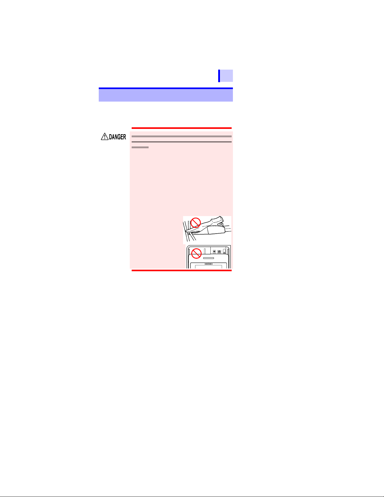
3.3 Measuring Voltage
Do not clamp two lines.
Shutter
79
3.3 Measuring Voltage
The instrument measures the voltage of an external circuit,
e.g., commercial power supply.
AC and DC are distinguished automatically.
1
To prevent damage to the instrument and
personal injury, observe the precautions
below.
• Maximum rated voltage to ground: 1,000
V AC (CAT III), 600 V AC (CAT IV)
• Do not conduct measurement exceeding
these voltages to ground.
• Maximum input voltage: 750 V AC, 1,000 V
DC
Do not conduct measurement exceeding
this maximum input voltage.
• Maximum input frequency: 70 Hz
Do not conduct measurement exceeding this maximum input frequency.
• Do not short-circuit a line voltage
applied with the
tip of test lead.
• Do not use the
instrument if the
shutter is broken.
2
3
4
5
6
7
8
9
10
11
付録
索引
Find Quality Products Online at: sales@GlobalTestSupply.com
www.GlobalTestSupply.com
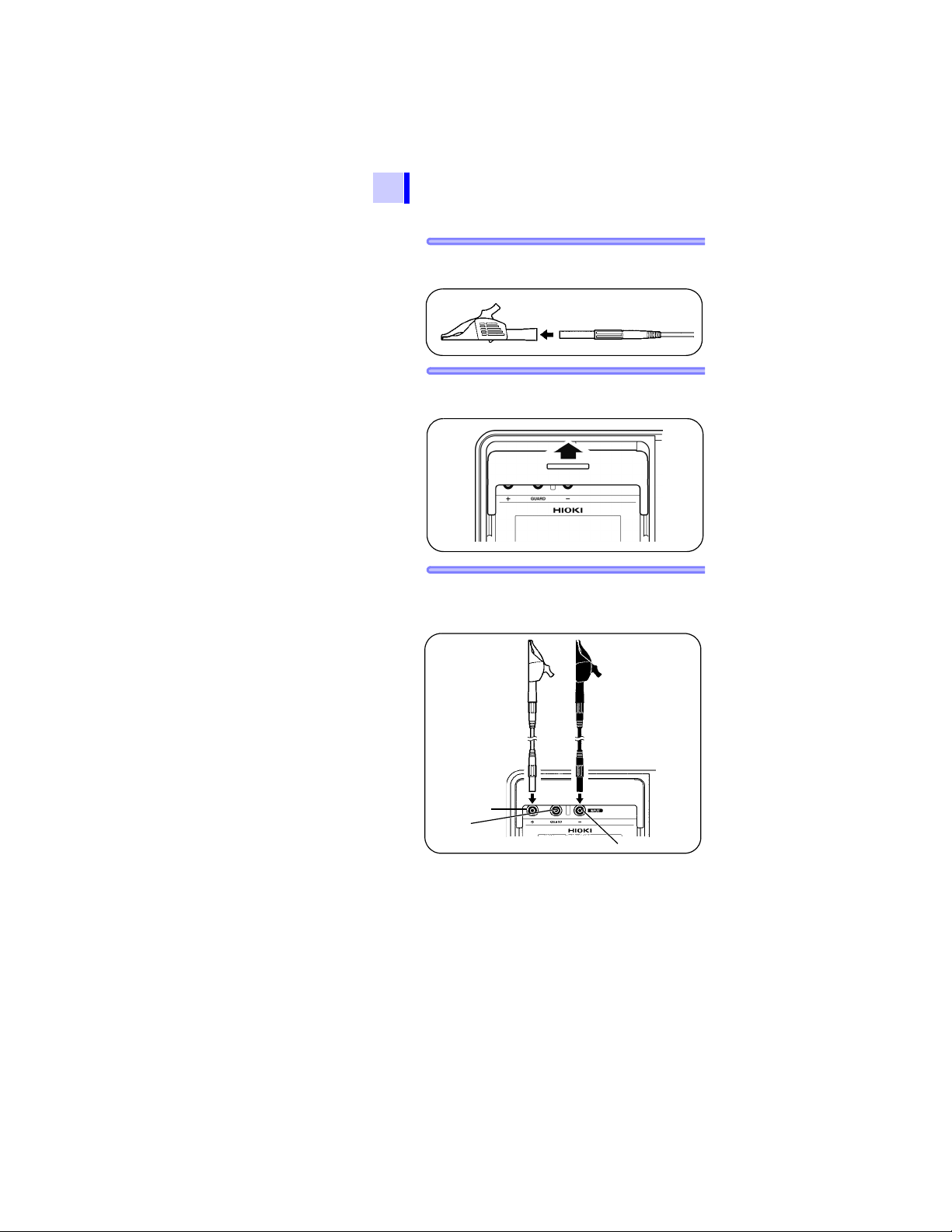
80
+ terminal
- terminal
GUARD
terminal
Test lead (Red) Test lead (Black)
3.3 Measuring Voltage
Procedure
1. Connect alligator clips to the ends of test
2. Move the shutter to reveal the + and -
3. Connect the red test lead to the + termi-
leads. Insert it fully.
terminals.
nal and the black test lead to the - terminal. Fully insert the test leads.
Find Quality Products Online at: sales@GlobalTestSupply.com
www.GlobalTestSupply.com
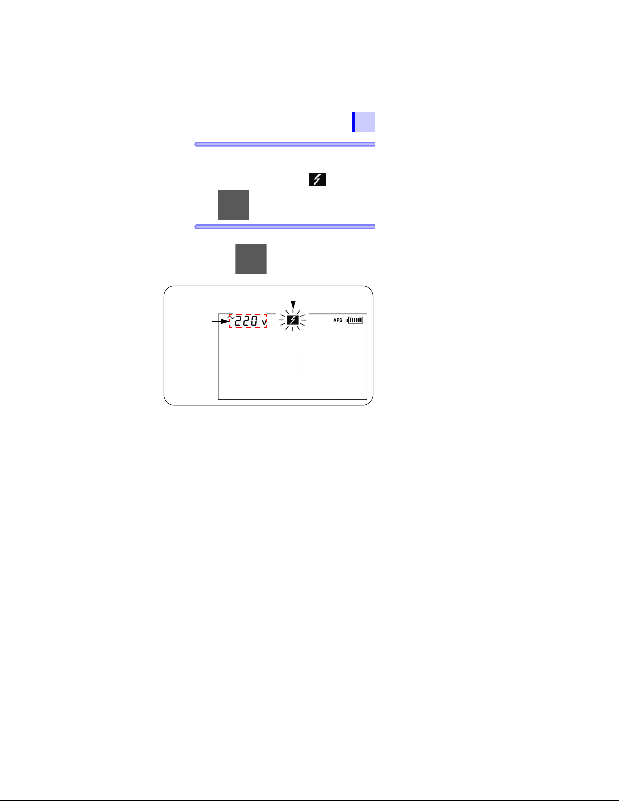
3.3 Measuring Voltage
Measured
voltage
Blinking
81
4. Clip the ends of the test lead s to the cir-
cuit to be tested. When the voltage
exceeds 50 V, the mark and
1
key lamp blink.
5. Read the voltage indication.
The key is not used.
2
3
4
5
6
7
8
9
10
11
付録
索引
Find Quality Products Online at: sales@GlobalTestSupply.com
www.GlobalTestSupply.com
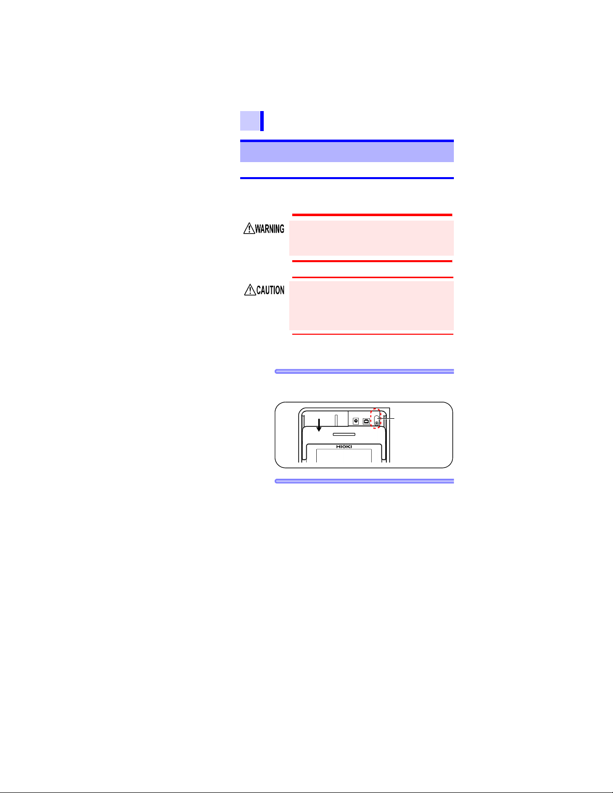
82
Move the shutter.
Temperature
sensor terminal
3.4 Measuring Temperature
3.4 Measuring Temperature
3.4.1 Measurement Procedure
Do not attempt to measure the temperature of objects carrying a voltage. Doing
so will result in a short-circuit accident or
an electrocution accident.
Temperature sensors may be damaged by
high voltage or static electricity. Do not
expose the temperature sensor to excessive
impact, or allow the cable to be bent, since
malfunction or faulty connection may result.
Procedure
1. Move the shutter to reveal th e tempera-
ture sensor terminal.
2. Connect the temperature sensor to the
temperature sensor terminal.
Find Quality Products Online at: sales@GlobalTestSupply.com
www.GlobalTestSupply.com
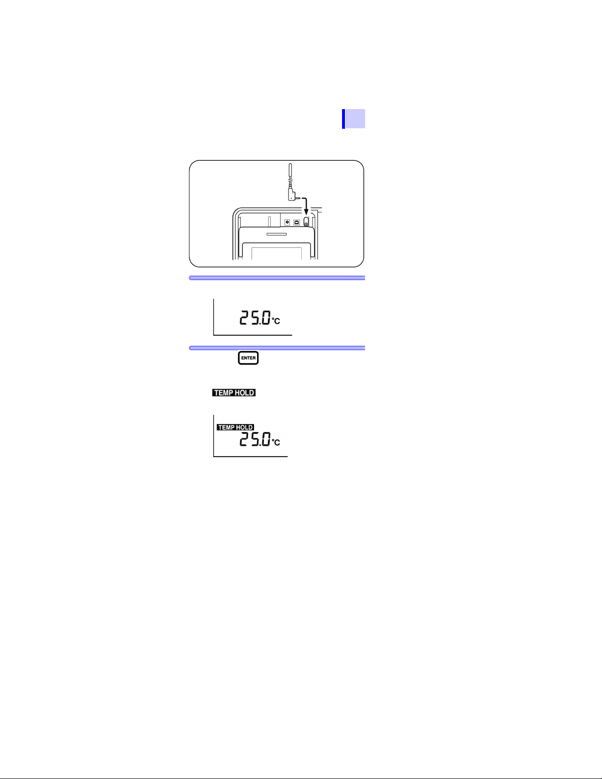
3.4 Measuring Temperature
After measuring temperature
(When the resistance is not measured.)
Temperature measurement begins automatically.
3. Read the temperature indication.
83
1
2
3
4
5
6
4. Press key or disconnect the tem-
perature sensor to stop measurement.
lights up and the last mea-
surement is held.
Detailing the above displaySee 6.3.2 "Clearing
Indications of Temperature and Humidity Stored
Data" (page 135).
7
8
9
10
11
付録
索引
Find Quality Products Online at: sales@GlobalTestSupply.com
www.GlobalTestSupply.com
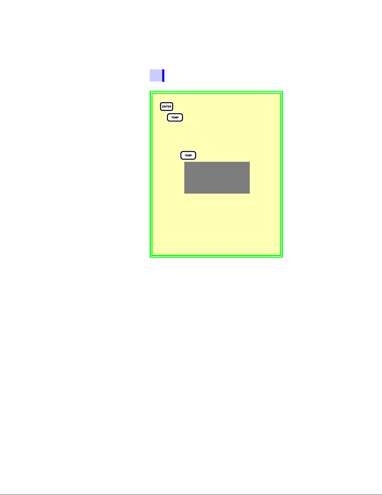
84
After measuring temperature
(Disconnecting the temperature sensor,
resistance value is held)
3.4 Measuring Temperature
• If temperature measurement is stopped using the
key, measurement may be resumed by pressing
the key.
• When an insulation resistance measurement is held, if
the temperature sensor is disconnected, the temperature indication switches to the elapsed time indica tion at
the time of insulation resistance measurement. To display the held temperature instead of the elapsed time,
press the key. (The tempe rature will bli nk.)
• Held measurement values are cleared when power is
turned off. To save the data, use the memory function.
See 5.1.1 "Manual Recording (Recording result of one mea-
surement session)" (page 107).
• Settings cannot be edited during temperature measure-
ment. To edit settings, stop temperature measurement.
•[OF] means exceeding 70.0°C.
[-OF] means below -10.0°C.
Find Quality Products Online at: sales@GlobalTestSupply.com
www.GlobalTestSupply.com

Advanced
4.1 Using Timer
85
Measurement
4
4.1 Using Timer
What is it used for?
If the timer is set during insulation resistance measurement,
the measurement automatically ends at the set time.
Selectable time: 30 sec. to 30 min. (When setting over 1
minute, time increments or decrements in minutes.)
4.1.1 Setting Timer/Conducting Insulation Resistance Measurement
Procedure
Used to set the instrument to automatically stop at a specified time.
1. When the instrument is in a standby
state, press the key.
The time indication will blink.
1
2
3
4
5
6
7
8
9
10
2. Press the key to set the time.
Find Quality Products Online at: sales@GlobalTestSupply.com
www.GlobalTestSupply.com
11
付録
索引
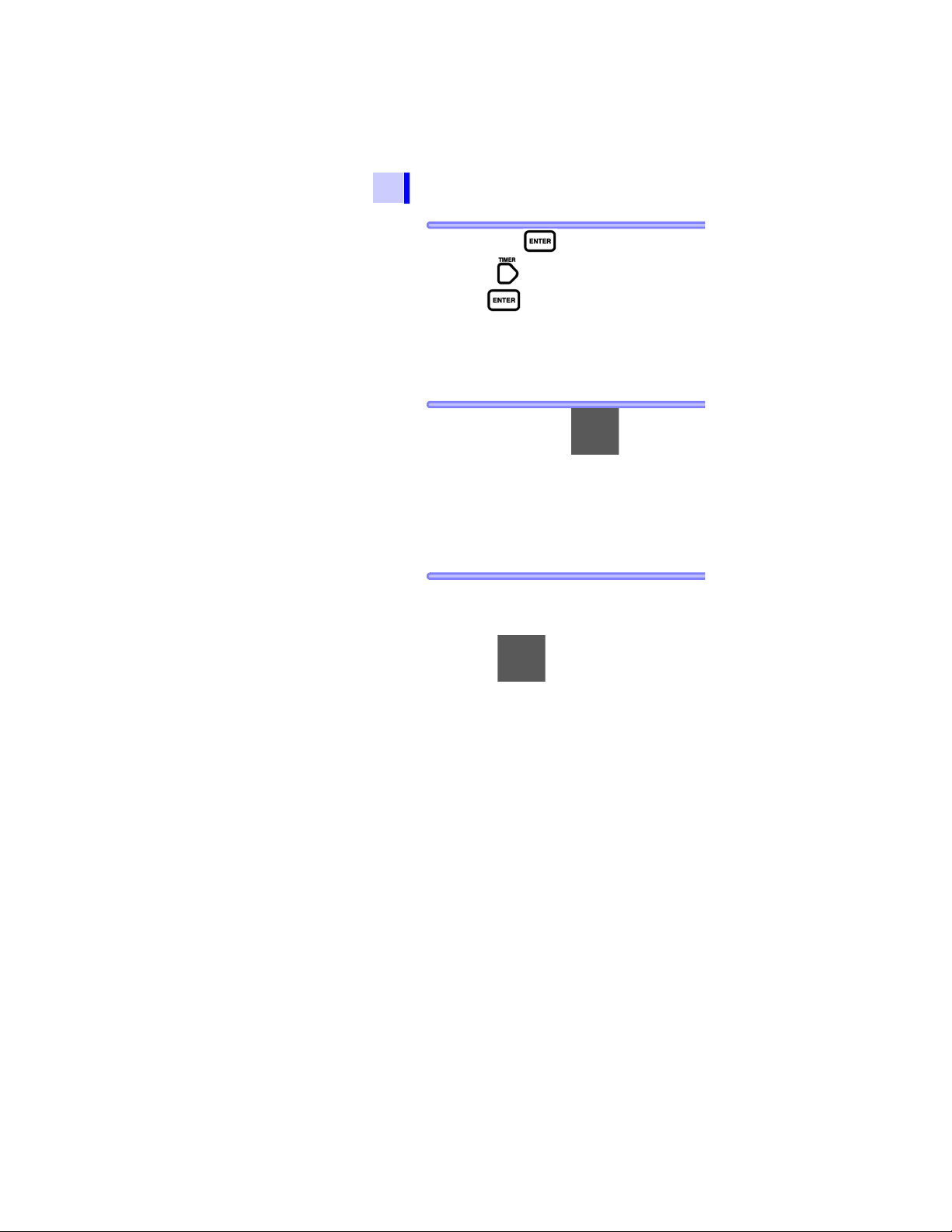
86
4.1 Using Timer
3. Press the key to confirm the entry.
If the key is pressed without pressing
the key, the instrument returns to a
standby state with the time unchanged.
When the timer is successfully set, the
[TIMER] indicator lights.
4. Holding down the key for longer
than one second generates a test voltage,
and measurement begins.
At the bottom of the screen, remaining
time to completion of measurement is
displayed.
5. After the set time has elapsed, the
instrument automatically stops measurement.
If the key is pressed, the instrument immediately stops measurement
regardless of the remaining time.
Elapsed time at the completion of mea-
surement is displayed at the bottom of
the screen.
When the timer is set, auto power off is
disabled.
Find Quality Products Online at: sales@GlobalTestSupply.com
www.GlobalTestSupply.com

Procedure
4.1 Using Timer
87
Timer not used
1. When the instrument is in a standby
state, press the key.
The time indication will blink.
1
2
3
4
2. Press the key to select - - min - - s.
- - min - - s is also selected by pressing
the key.
3. Press the key to confirm the
entry.
[TIMER] indicator is turned off.
5
6
7
8
9
10
11
付録
索引
Find Quality Products Online at: sales@GlobalTestSupply.com
www.GlobalTestSupply.com

88
4.1 Using Timer
Procedure
Checking set time
1. When the instrument is in a standby
state, press the key.
The currently set time blinks. Check the
time.
2. Press the or key to return to the
previous screen.
Find Quality Products Online at: sales@GlobalTestSupply.com
www.GlobalTestSupply.com

4.2 Displaying PI and DAR
Resistance 10 min. after voltage application
Resistance 1 min. after voltage application
Resistance 1 min. after voltage application
Resistance 15 sec. after voltage application
Resistance 1 min. after voltage application
Resistance 30 sec. after voltage application
4.2 Displaying PI and DAR
89
Used to check whether insulation re sistance increases with time after a
What is it used for?
• The instrument automatically calculates and displays PI
(polarization index) and DAR (dielectric absorption ratio),
which are used as the criteria to determine the quality of
insulation.
Both measurements show a degree of change in insulation resistance with time after a test voltage is applied.
Appendix 3 "Example of PI Criteria (Polarization Index)" (page 166)
• PI and DAR are calculated using the formulae below from
resistance values measured twice after a voltage is
applied. For PI, the measurement interval may be userset.
See 6.1 "Changing and Checking In terval Settin g for PI Calcula tion"
(page 125).
PI 10/1min =
DAR 1min/15s =
DAR 1min/30s =
To determine DAR, press the key to
turn off [
measurement.
voltage is applied.
(When the PI value or the DAR value is close to 1, the instrument determines that the insulation of the
object under test is deteriorated.)
AVE] on the screen before starting
1
2
3
4
5
6
7
8
9
10
11
付録
索引
Find Quality Products Online at: sales@GlobalTestSupply.com
www.GlobalTestSupply.com

90
4.2 Displaying PI and DAR
Procedure
1. Measure insulation resistan ce.
2. Stop measurement.
3. Press the key several times to
To determine PI, continue measurement
for 10 minutes (for a default time setting).
To determine DAR, continue measurement
for one minute.
display PI, DAR 1 min/15 s, or DAR 1
min/30 s.
Every time the key is pressed the
indication on the LCD changes in the
order of resistance
min/15 s DAR 1 min/30 s PI
resistance current , etc.
current DAR 1
Find Quality Products Online at: sales@GlobalTestSupply.com
www.GlobalTestSupply.com
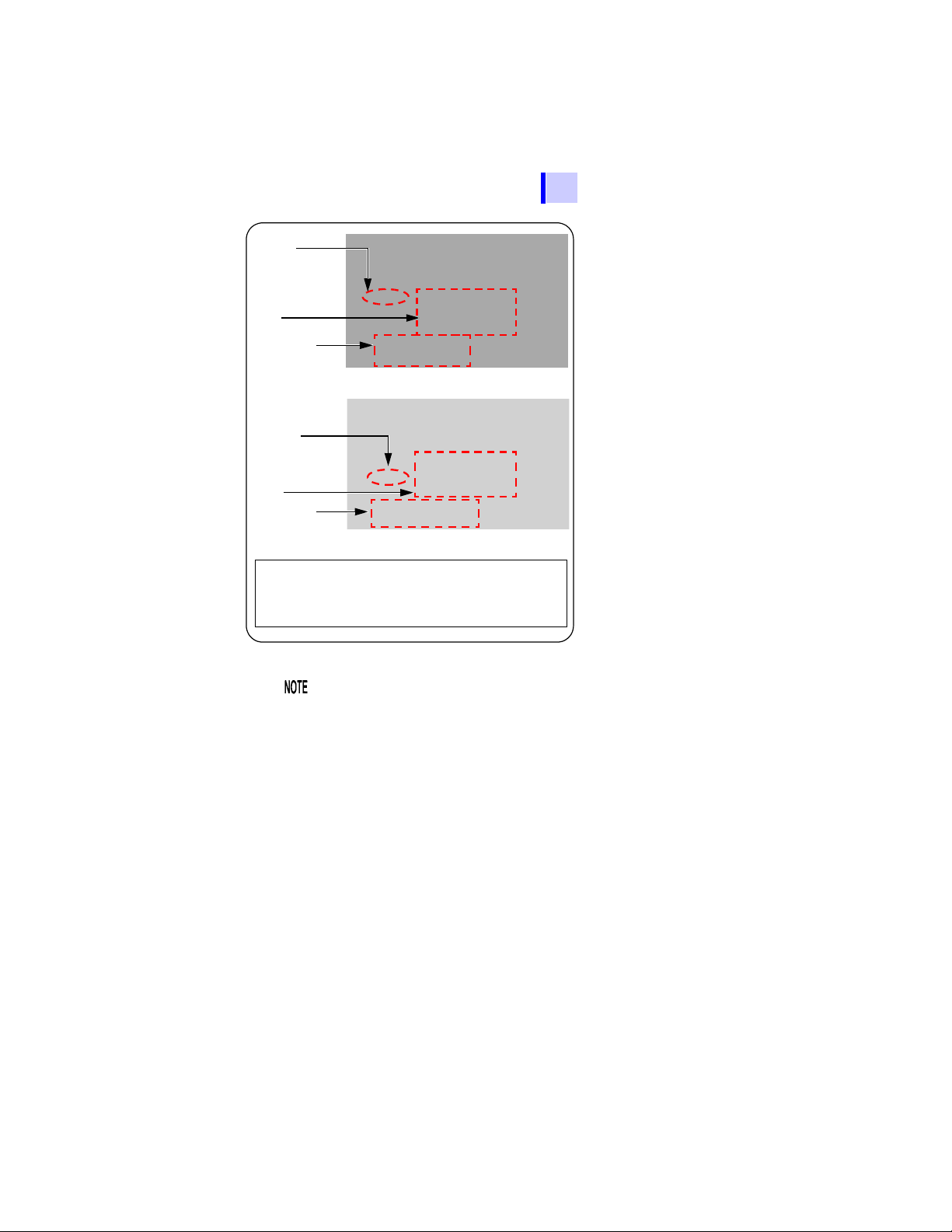
4.2 Displaying PI and DAR
DAR
PI
Resistance
Right: 1st measurement
Left : 2nd measurement
Right: 1st
Left : 2nd
1st : 1 min.
2nd : 10 min.
Measurement
Resistance
Right : 1st 30 G
Left : 2nd 60 G
Substitute into the formula; PI 10/1min=Resistance 10
min. after voltage application divided by resistance 1
min. after voltage application.
PI in the example above is:
2.00=60.0 G / 30.0 G
Interval
Measurement
Interval
91
1
2
3
4
5
6
7
8
• If measurement ends before the set time
elapses, [
• When [TC] is on (temperature compensation
mode), PI and DAR cannot be displayed.
• In the step voltage test mode, PI or DAR
cannot be displayed.
- - - ] appears on the screen.
9
10
11
付録
索引
Find Quality Products Online at: sales@GlobalTestSupply.com
www.GlobalTestSupply.com

92
4.2 Displaying PI and DAR
Blinking resistance indication on PI or
DAR display screen
When the resistance indication blinks, the
displayed reading may be incorrect. (Insulation resistance changed rapidly before
end of set specified time, affecting measurement range so that the internal circuit
failure to respond)
When the resistance reading blinks, regard
the PI or DAR value as a reference. Perform measurement again.
The table below shows special indications
for PI and DAR.
PI, DAR Conditions
• One or more resistance values could not be acquired.
([- - -] appears in the resistance field.)
• One or more resistance val-
- - -
>999
<0.01
ues exceeded measurement range.
([
OF] appears in the resis-
tance field.)
• The 1st measurement was
0.00 M.
PI or DAR is larger than 999.
PI or DAR is smaller than
0.01.
Find Quality Products Online at: sales@GlobalTestSupply.com
www.GlobalTestSupply.com
4.3 Temperature Compensation (TC)
4.3 Temperature Compensation
(TC)
Used to acquire insulation resis-
93
What is it used for?
• The instrument converts measured resistance to the
resistance at a reference temperature and displays the
result.
• There are 10 compensation methods (compensation
tables) available depending on the object under test and
its characteristics. Choose the appropriate temperature
compensation table.
• The reference temperature may be set to an arbitrary
level. The selectable reference temperature ranges vary
depending on the compensation table used.
• The convertible measurement temperature ranges also
vary depending on the compensation table used.
See Appendix 4 "Temperature Compensation Table" (page 167).
tance at a temperature differing from
the actual temperature at which
measurement is performed.
1
2
3
4
5
6
4.3.1 Performing Temperature Compensa-
tion
Procedure
1. Measure temperature and insulation
resistance. The measurements are held
upon completion.
(Either may be measured first.)
3.2 "Measuring Insulation Resistance" (page 62)
See 3.4 "Measuring Temperature" (page 82).
The temperature may also be entered with
keys.
See 6.3 "Entering Temperature and Humidity
Measured with External Thermometer and
Hygrometer" (page 131).
In the step voltage test mode ([STEP] is on),
temperature compensation is unavailable.
Exit the step voltage test mode.
See 4.4.3 "Exiting Step Voltage Test Mode"
(page 103).
7
8
9
10
11
付録
索引
Find Quality Products Online at: sales@GlobalTestSupply.com
www.GlobalTestSupply.com
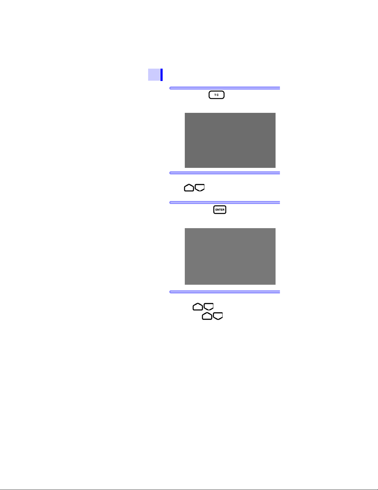
94
4.3 Temperature Compensation (TC)
2. Press the key.
[TABLE No.] blinks.
3. Choose a table No. from 0 to 9 using the
4. Press the key to confirm the
choice of table No.
The reference temperature blinks.
key.
5. Adjust the reference temperature using
the key.
If the keys are held down
simultaneously, the reference temperature is returned to its default.
(40°C for table 9 and 20°C for the rest.)
Find Quality Products Online at: sales@GlobalTestSupply.com
www.GlobalTestSupply.com
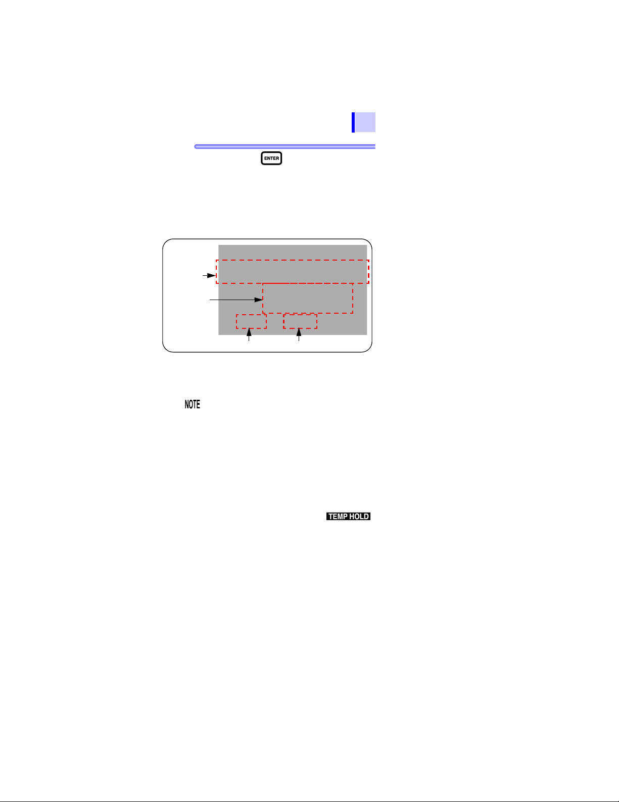
4.3 Temperature Compensation (TC)
Bar graph
(Value before
compensation)
Digital value
(Value after
compensation)
Actual Measurement Temperature
Reference Temperatur e
95
6. Press the key to confirm the ref-
erence temperature.
[TC] lights up and the instrument enters
temperature compensation mode.
The LCD displays the resistance at the
reference temperature converted from
the measurement.
1
2
3
4
5
6
The bar graph shows the value before compensation.
• If the resistance before compensation
exceeds the measurement range, it
cannot be converted and the LCD
displays [
• After the instrument is placed in
temperature compensation mode,
measurement or input of temperature and
measurement of insulation resistance
may be conducted.
• However, if the instrument is placed in
temperature compensation mode when
the temperature is not held (
is off), measure or enter temperature
before measuring resistance. You cannot
measure resistance first.
- - -].
7
8
9
10
11
付録
索引
Find Quality Products Online at: sales@GlobalTestSupply.com
www.GlobalTestSupply.com
 Loading...