

Hilti TE 700-AVR Operating Instructions Manual
TE 700-AVR
Operating instructions en
Mode d’emploi fr
Manual de instrucciones es
Manual de instruções pt
Printed: 08.07.2013 | Doc-Nr: PUB / 5071172 / 000 / 03

1
This Product is Certified
Ce produit est certifié
Este producto esta certificado
Este produto está certificado
C US
꺁꺃깹깸
깾
깿
꺂꺀
깺꺂
깻
깼
깽
Printed: 08.07.2013 | Doc-Nr: PUB / 5071172 / 000 / 03
2
3
4
5
6
Printed: 08.07.2013 | Doc-Nr: PUB / 5071172 / 000 / 03
ORIGINAL OPERATING INSTRUCTIONS
TE 700‑AVR breaker
It is essential that the operating instructions
are read before the power tool is operated for
the first time.
Always keep these operating instructions together with the power tool.
Ensure that the operating instructions are
with the power tool when it is given to other
persons.
Contents Page
1 General information 1
2Description 2
3 Accessories, consumables 4
4 Technical data 5
5 Safety instructions 6
6Beforeuse 8
7 Operation 8
8 Care and maintenance 10
9 Troubleshooting 11
10 Disposal 12
11 Manufacturer’s warranty - tools 12
1 General information
1.1 Safety notices and their meaning
DANGER
Draws attention to imminent danger that will lead to
seriousbodilyinjuryorfatality.
WARNING
Draws attention to a potentially dangerous situation that
could lead to serious personal injury or fatality.
CAUTION
Draws attention to a potentially dangerous situation that
could lead to slight personal injury or damage to the
equipment or other property.
NOTE
Draws attention to an instruction or other useful information.
1 These numbers refer to the corresponding illustrations. The illustrations can be found on the fold-out cover
pages. Keep these pages open while studying the operating instructions.
In these operating instructions, the designation “the
power tool” always refers to the TE 700‑AVR breaker.
Components, operating controls and indicators 1
Grip
@
On / off switch
;
Supply cord
=
Theft protection indicator (optional)
%
Service indicator
&
Power level indicator
(
Power level selection switch
)
Side handle
+
Knob
§
Chuck
/
Ventilation slots
:
Function selector switch
·
1.2 Explanation of the pictograms and other
information
Warning signs
General
warning
Warning:
electricity
Warning: hot
surface
en
1
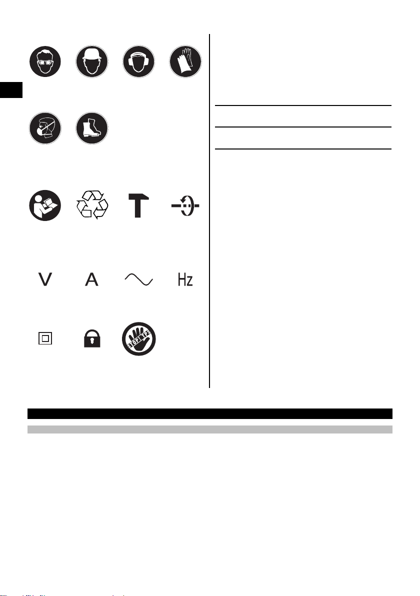
Obligation signs
Wear eye
en
protection
Wear a hard
hat
Wear ear
protection
Wear
protective
gloves
Location of identification data on the power tool
The type designation and serial number can be found
on the type identification plate on the machine or tool.
Makeanoteofthisdatainyouroperatinginstructions
and always refer to it when making an enquiry to your
Hilti representative or service department.
Type:
Generation: 01
Wear
breathing
protection
Wear safety
shoes
Symbols
Serial no.:
Read the
operating
instructions
before use
Volts Amps Alternating
Double
insulated
Return waste
material for
recycling.
Lock symbol Equipped
Chiseling Chisel
current
with theft
protection
system
position
adjustment
Hertz
2 Description
2.1 Use of the product as directed
The power tool is an electrically-powered breaker with pneumatic hammer mechanism for medium heavy chiseling
work.
The power tool is designed for removing and breaking up concrete, masonry and stone.
Working on materials hazardous to the health (e.g. asbestos) is not permissible.
Nationally applicable industrial safety regulations must be observed.
The power tool is designed for professional use and may be operated, serviced and maintained only by trained,
authorized personnel. This personnel must be informed of any special hazards that may be encountered. The power
tool and its ancillary equipment may present hazards when used incorrectlybyuntrainedpersonnelorwhenusednot
as directed.
The working environment may be as follows: construction site, workshop, renovation, conversion or new construction.
Thepowertoolmaybeusedonlyinadryenvironment.
Do not use the power tool where there is a risk of fire or explosion.
The power tool may be operated only when connected to a power supply providing a voltage and frequency in
compliance with the information given on its type identification plate.
2

To avoid the risk of injury, use only genuine Hilti accessories and insert tools.
Observe the information printed in the operating instructions concerning operation, care and maintenance.
Modification of the power tool or tampering with its parts is not permissible.
2.2 Chuck
TE‑Y chuck
2.3 Switch
On / off switch
Power level selector switch (100%, 70%)
2.4 Grips (with soft synthetic foam rubber covering)
Vibration-absorbing grip
Vibration-absorbing, rotatable and pivotable side grip
2.5 Lubrication
Gearing and hammering mechanism with separate lubrication chambers
2.6 Active vibration reduction
The power tool is equipped with an AVR active vibration reduction system which reduces vibration significantly
compared to power tools without active vibration reduction.
2.7 TPS theft protection system (optional)
The power tool may be equipped with the TPS Theft Protection System as an option. If the power tool is equipped
with this optional feature it can be unlocked and made ready for operation only through use of the corresponding TPS
key (see section “Operation / TPS theft protection system (optional)”).
2.8 Protective features
Temperature and vibration protection provided by separating the plastic housing case and grips from the internal
machine.
Electronic restart interlock to prevent the power tool starting unintentionally after an interruption in the electric supply
(see section “Troubleshooting”).
Electronics with self-acting protective system against overvoltage and overheating.
en
2.9 LED indicators
Service indicator LED (see section “Care and maintenance / service indicator”)
Theft protection system indicator (optional) (see section “Operation / TPS theft protection system (optional)”)
Power level indicator (see section “Operation / setting chiseling power”)
2.10 Items supplied as standard
1 Power tool
1Sidehandle
1 Grease
1 Cleaning cloth
1 Operating instructions
1 Hilti toolbox
2.11 Using extension cords
Use only extension cords of a type approved for the application and with conductors of adequate cross section.
The power tool may otherwise lose performance and the extension cord may overheat. Check the extension cord for
damage at regular intervals. Replace damaged extension cords.
3

Recommended minimum conductor cross section and max. cable lengths
Conductor cross section 14 AWG 12 AWG
Mains voltage 120 V 50 ft 125 ft
Do not use extension cords with 16 AWG conductor cross section.
en
2.12 Using extension cords outdoors
When working outdoors, use only extension cords that are approved and correspondingly marked for this application.
2.13 Using a generator or transformer
This power tool may be powered by a generator or transformer when the following conditions are fulfilled: The unit
must provide a power output in watts of at least twice the value printed on the type identification plate on the power
tool. The operating voltage must remain within +5% and -15% of the rated voltage at all times, frequency must be in
the 50 – 60 Hz range and never above 65 Hz, and the unit must be equipped with automatic voltage regulation and
starting boost.
Never operate other power tools or appliances from the generator or transformer at the same time. Switching other
power tools or appliances on and off may cause undervoltage and / or overvoltage peaks, resulting in damage to the
power tool.
3 Accessories, consumables
Designation
TPS Theft Protection System with
Company Card, Company Remote
and TPS‑K key
Dust removal module TE DRS‑B
Use the Hilti chisels or other tools listed below. With these you will achieve higher performance and longer
lifetime as the power tool and chisels have been optimized as a system.
TE‑Y chuck /
tool description
Pointed chisels TE‑YP SM 28 280 11
TE‑YP SM 36 360 14
TE‑YP SM 50 500 19
TE‑YP SM 70 700 27
Flat chisels TE‑YP FM 28 280 11
TE‑YP FM 36 360 14
TE‑YP FM 50 500 19
TE‑YP FM 70 700 27
Wide-flat chisels TE‑YP
SPM 5/28
TE‑YP
SPM 5/36
TE‑YP
SPM 8/28
TE‑YP
SPM 12/36
TE‑SP
SPM 12/50
Flexible chisel TE‑Y
BSPM 800
Short designation
Width (mm) Length (mm)
50 280 2 11
50 360 2 14
80 280 3 11
120 360 4³⁄₄ 14
120 500
150 650 6 25¹⁄₂
Item number, description
206999, optional
Width in
inches
4³⁄₄
Length in
inches
19
4

TE‑Y chuck /
tool description
Scraper / flexible chisel TE‑YP
Hollow chisel TE‑Y
Channel chisel TE‑Y
Scoop chisel TE‑Y
Mortar chisel TE‑Y
Pointed flat chisel TE‑Y SPI 50 150 650 6 25¹⁄₂
Tamping plate TE STP
Shank TE‑Y SS 300
Bushing tool
(one-piece)
Bushing head TP SKHM 40 40 X 40 1¹⁄₂ X 1¹⁄₂
Earth rod rammer TP‑TKS 15 Inside ∅ 15
SPMK 5/28
TE‑YP
SPMK 12/50
HM 2.8/28
KM 2.2/28
TE‑Y
KM 3.6/28
KMG 3.6/28
FGM 3.8/28
150/150
TP‑Y
SKHM 40
TP SKHM 60 60 X 60 2 X 2
TP‑TKS 20 Inside ∅ 20
TP‑TKS 25 Inside ∅ 25
TP‑TKS ¹⁄₂" Inside ∅ ¹⁄₂
TP‑TKS ⁵⁄₈" Inside ∅ ⁵⁄₈
TP‑TKS ³⁄₄" Inside ∅ ³⁄₄
Width (mm) Length (mm)
50 280 2 11
120 500 4³⁄₄ 19
28 280 1 11
22 280 ⁷⁄₈ 11
36 280 1¹⁄₂ 11
36 280
38 280 ¹⁵⁄₁₆ 11
150 X 150 6 X 6
40 X 40 250
Width in
inches
1¹⁄₂
1¹⁄₂ X 1¹⁄₂
Length in
inches
11
11³⁄₄
10
en
4 Technical data
Right of technical changes reserved.
NOTE
The power tool is available in various voltage ratings. Please refer to the power tool’s type identification plate for
details of its voltage, current and input power ratings.
Rated voltage, TE 700‑AVR 120 V
Rated current input 10.8 A
Mains frequency 50…60 Hz
Power tool TE 700‑AVR
Weight 7.9 kg (17.42 lb)
Dimensions (L x W x H) 564 mm (22.2") x 125 mm (4.92") x 248 mm (9.76")
Single impact energy 11.5 J
Chuck TE‑Y
Hammering frequency under load 46 Hz
5

Information about the power tool and its applications
Protection class Protection class II (double insulated)
5 Safety instructions
en
5.1 General Power Tool Safety Warnings
a)
WARNING
Read all safety warnings and instructions. Failure
to follow the warnings and instructions may result
in electric shock, fire and/or serious injury. Save all
warnings and instructions for future reference.
The term “power tool” in the warnings refers to
your mains-operated (corded) power tool or batteryoperated (cordless) power tool.
5.1.1Workareasafety
a) Keep work area clean and well lit. Cluttered or dark
areas invite accidents.
b) Do not operate power tools in explosive atmo-
spheres, such as in the presence of flammable
liquids, gases or dust. Power tools create sparks
which may ignite the dust or fumes.
c) Keep children and bystanders away while operat-
ing a power tool. Distractions can cause you to lose
control.
5.1.2 Electrical safety
a) Power tool plugs must match the outlet. Never
modify the plug in any way. Do not use any adapter
plugs with earthed (grounded) power tools. Un-
modified plugs and matching outlets will reduce risk
of electric shock.
b) Avoid body contact with earthed or grounded
surfaces such as pipes, radiators, ranges and
refrigerators. There is an increased risk of electric
shock if your body is earthed or grounded.
c) Do not expose power tools to rain or wet condi-
tions. Water entering a power tool will increase the
risk of electric shock.
d) Do not abuse the cord. Never use the cord for
carrying, pulling or unplugging the power tool.
Keep cord away from heat, oil, sharp edges or
moving parts. Damaged or entangled cords increase
theriskofelectricshock.
e) When operating a power tool outdoors, use an
extension cord suitable for outdoor use. Use of
a cord suitable for outdoor use reduces the risk of
electric shock.
f) If operating a power tool in a damp location is
unavoidable, use a residual current device (RCD)
protected supply. Use of an RCD reduces the risk
of electric shock.
5.1.3 Personal safety
a) Stay alert, watch what you are doing and use
common sense when operating a power tool. Do
not use a power tool while you are tired or under
the influence of drugs, alcohol or medication. A
moment of inattention while operating power tools
may result in serious personal injury.
b) Use personal protective equipment. Always wear
eye protection. Protective equipment such as dust
mask, non-skid safety shoes, hard hat, or hearing
protection used for appropriate conditions will reduce
personal injuries.
c) Prevent unintentional starting. Ensure the switch
is in the off‐position before connecting to power
source and/or battery pack, picking up or carrying
the tool. Carrying power tools with your finger on the
switch or energising power tools that have the switch
on invites accidents.
d) Remove any adjusting key or wrench before turn-
ing the power tool on. A wrench or a key left attached to a rotating part of the power tool may result
in personal injury.
e) Do not overreach. Keep proper footing and bal-
ance at all times. This enables better control of the
power tool in unexpected situations.
f) Dress properly. Do not wear loose clothing or
jewellery. Keep your hair, clothing and gloves
away from moving parts. Loose clothes, jewellery
or long hair can be caught in moving parts.
g) If devices are provided for the connection of dust
extraction and collection facilities, ensure these
are connected and properly used. Use of dust
collection can reduce dust-related hazards.
5.1.4 Power tool use and care
a) Do not force the power tool. Use the correct
power tool for your application. The correct power
tool will do the job better and safer at the rate for
which it was designed.
b) Do not use the power tool if the switch does not
turn it on and off. Any power tool that cannot be
controlled with the switch is dangerous and must be
repaired.
c) Disconnect the plug from the power source
and/or the battery pack from the power tool
before making any adjustments, changing
accessories, or storing power tools. Such
preventive safety measures reduce the risk of
starting the power tool accidentally.
d) Store idle power tools out of the reach of chil-
dren and do not allow persons unfamiliar with the
power tool or these instructions to operate the
power tool. Power tools are dangerous in the hands
of untrained users.
e) Maintain power tools. Check for misalignment or
binding of moving parts, breakage of parts and
any other condition that may affect the power
tool’s operation. If damaged, have the power tool
6

repaired before use. Many accidents are caused by
poorly maintained power tools.
f) Keep cutting tools sharp and clean. Properly main-
tained cutting tools with sharp cutting edges are less
likely to bind and are easier to control.
g) Use the power tool, accessories and tool bits etc.
in accordance with these instructions taking into
account the working conditions and the work to
be performed. Use of the power tool for opera-
tions different from those intended could result in a
hazardous situation.
5.1.5 Service
a) Have your power tool serviced by a qualified repair
person using only identical replacement parts.
This will ensure that the safety of the power tool is
maintained.
5.2 Hammer safety warnings
a) Wear ear protectors. Exposure to noise can cause
hearing loss.
b) Use auxiliary handles, if supplied with the tool.
Loss of control can cause personal injury.
c) Hold power tool by insulated gripping surfaces,
when performing an operation where the cutting
accessory may contact hidden wiring or its own
cord. Cutting accessory contacting a "live" wire may
make exposed metal parts of the power tool "live"
and could give the operator an electric shock.
5.3 Additional safety instructions
5.3.1 Personal safety
a) Store power tools, when not in use, in a secure
place. When not in use, power tools must be
stored in a dry, high place or locked away out of
reach of children.
b) Always hold the power tool securely with both
hands on the grips provided. Keep the grips dry,
clean and free from oil and grease.
c) Improve the blood circulation in your fingers by
relaxing your hands and exercising your fingers
during breaks between working.
d) Always lead the supply cord and extension cord
away from the power tool to the rear while working. This helps to avoid tripping over the cord while
working.
e) Children must be instructed not to play with the
power tool.
f) The power tool is not intended for use by children,
by debilitated persons or those who have received
no instruction or training.
g) WARNING: Some dust created by grinding, sand-
ing, cutting and drilling contains chemicals known
to cause cancer, birth defects, infertility or other
reproductive harm; or serious and permanent respiratory or other injury. Some examples of these
chemicals are: lead from lead-based paints, crystalline silica from bricks, concrete and other masonry
products and natural stone, arsenic and chromium
from chemically-treated lumber. Your risk from these
exposures varies, depending on how often you do
this type of work. To reduce exposure to these
chemicals, the operator and bystanders should
work in a well-ventilated area, work with approved safety equipment, such as respiratory protection appropriate for the type of dust generated,
and designed to filter out microscopic particles
and direct dust away from the face and body.
Avoid prolonged contact with dust. Wear protective clothing and wash exposed areas with soap
and water. Allowing dust to get into your mouth,
eyes, or to remain on your skin may promote absorption of harmful chemicals.
5.3.2 Electrical safety
a) Before beginning work, check the working area
(e.g. using a metal detector) to ensure that no
concealed electric cables or gas and water pipes
are present. External metal parts of the power tool
may become live, for example, when an electric cable
is damaged accidentally. This presents a serious risk
of electric shock.
b) Check the power tool’s supply cord at regular
intervals and have it replaced by a qualified specialist if found to be damaged. If the power tool’s
supply cord is damaged it must be replaced with
a specially-prepared supply cord available from
Hilti Customer Service. Check extension cords
at regular intervals and replace them if found to
be damaged. Do not touch the supply cord or
extension cord if it is damaged while working.
Disconnect the supply cord plug from the power
outlet. Damaged supply cords or extension cords
present a risk of electric shock.
c) Dirty or dusty power tools which have been used
frequently for work on conductive materials
should be checked at regular intervals at a Hilti
Service Center. Under unfavorable circumstances,
dampness or dust adhering to the surface of
the power tool, especially dust from conductive
materials, may present a risk of electric shock.
d) When working outdoors with an electric tool
check to ensure that the tool is connected to the
electric supply by way of a ground fault circuit
interrupter (GFCI) with a rating of max. 30 mA
(tripping current). Use of a ground fault circuit
interrupter reduces the risk of electric shock.
e) Use of a ground fault circuit interrupter (GFCI)
with a maximum tripping current of 30 mA is
recommended.
f) Switch the power tool off and unplug the supply
cord in the event of a power failure or interruption
in the electric supply. This will prevent accidental
restarting when the electric power returns.
en
7
5.3.3 Work area
en
a) Ensure that the workplace is well ventilated. Ex-
posure to dust at a poorly ventilated workplace may
result in damage to the health.
b) Keep the workplace tidy. Objects which could
cause injury should be removed from the working area. Untidiness at the workplace can lead to
accidents.
c) If the work involves breaking right through, take
the appropriate safety measures at the opposite
side. Parts breaking away could fall out and / or fall
down and injure other persons.
d) Approval must be obtained from the site engineer
or architect prior to beginning the work. Work
6Beforeuse
CAUTION
Check the insert tool for damage or uneven wear each
time before use.
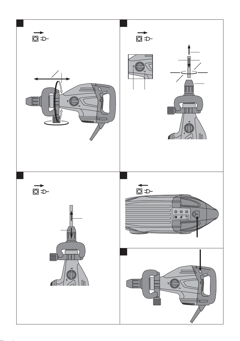
6.1 Fitting and adjusting the side grip 2
1. Disconnect the mains plug from the power outlet.
2. Release the side grip clamping band by turning the
knob.
on buildings and other structures may influence
the statics of the structure, especially when steel
reinforcing bars or load-bearing components are
cut through.
5.3.4 Personal protective equipment
The user and any other persons in the vicinity must
wear ANSI Z87.1-approved eye protection, a hard
hat, ear protection, protective gloves and breathing
protection while the machine is in use.
3. Relax the tension on the side grip (clamping band)
and slide it over the chuck and onto the shank.
4. Pivot the side grip into the desired position.
5. Secure the side grip by tightening the knob.
6.2 Unlocking the power tool (theft protection
system)
See section “Operation / TPS Theft Protection System
(optional)”.
6.3 Use of extension cords and generators or
transformers
See section “Description / use of extension cords”.
7Operation
DANGER
Always hold the power tool securely with both hands
on the grips provided. Keep the grips dry, clean and
free from oil and grease.
8
7.1 Preparing for use
CAUTION
Wear protective gloves when changing insert tools
as the insert tools get hot through use and they may
have sharp edges.
7.1.1 Fitting the insert tool 3
NOTE
The chisel can be adjusted to 24 different positions
(in 15° increments). This ensures that flat chisels and
shaped chisels can always be set to the optimum working
position.

1. Disconnect the mains plug from the power outlet.
2. Check that the connection end of the chisel is clean
and lightly greased. Clean it and grease it if necessary.
3. Check that the sealing lip of the dust shield is clean
and in good condition. Clean the dust shield if necessary or replace it if the sealing lip is found to
be damaged (please refer to the “Care and maintenance” section).
4. Push the chisel into the chuck and rotate it while
applying slight pressure until it engages in the guide
grooves.
5. Push the chisel further into the chuck until it is heard
to engage.
6. Check that the chisel has engaged correctly by
pulling it.
7. In order to positionthe tool, turn the functionselector
switch to the 'Turn chisel' position.
8. Rotate the chisel to the desired position.
9. In order to positionthe tool, turn the functionselector
switch to the 'Lock chisel' position.
10. Turn the chisel until it locks in place (24 catch
positions per revolution).
7.1.2 Removing the chisel 4
DANGER
Do not lay a hot insert tool down on flammable materials. This could cause the material to ignite, resulting in
afire.
1. Disconnect the mains plug from the power outlet.
2. Open the chuck by pulling back the locking sleeve.
3. Pull the chisel out of the chuck.
7.2 Operation
WARNING
If the power tool starts without pressing the on/off
switch when the supply cord is plugged back in after
unplugging, the power tool must be brought to Hilti
Service immediately.
WARNING
Unplug the supply cord if the on/off switch is found
to be faulty.
CAUTION
Working on the material may cause it to splinter. Use
eye protection, protective gloves, safety shoes and
a lightweight breathing mask. Flying fragments may
cause injury to the eyes or other parts of the body.
CAUTION
The work generates noise. Wear ear protectors. Exposure to noise can cause hearing loss.
7.2.1 TPS theft protection system (optional)
NOTE
The power tool may be equipped with the optional theft
protection system. If the power tool is equipped with this
feature, it can be unlocked and made ready for operation
only through use of the corresponding TPS key.
en
7.2.1.1 Unlocking the power tool 5
1. Plug the supply cord into the power outlet. The
yellow theft protection indicator LED flashes. The
power tool is now ready to receive the signal from
the TPS key.
2. Hold the TPS key or the TPS watch strap buckle
against the lock symbol. The power tool is unlocked
as soon as the yellow theft protection indicator LED
is no longer lit.
NOTE If, for example, the electric supply is briefly
interrupted due to a power failure or disconnected
when moving to a different workplace, the power
tool remains ready for operation for approx. 20 minutes. In the event of a longer interruption, the TPS
key must be used again to unlock the power tool.
7.2.1.2 Activation of the theft protection system for
the power tool
NOTE
Further detailed information on activation and use of the
theft protection system can be found in the operating
instructions for the theft protection system.
7.2.2 Chiseling
7.2.2.1 Working at low temperatures
NOTE
The power tool must reach a minimum operating temperature before the hammering mechanism begins to
operate.
Bring the power tool to the minimum operating temperature by switching it on and allowing it to run and warm up.
Bring the tip of the chisel into contact with the work surface at regular intervals (approx. every 30 sec.) to check
whether the hammering mechanism has begun to operate. Repeat the procedure if the hammering mechanism
does not begin to operate.
NOTE
As starting is electronically controlled, the power tool’s
starting characteristics may be different in cold conditions.
7.2.2.2 Switching on
1. Plug the mains plug of the supply cord into the
power outlet.
2. Press the on / off switch.
7.2.2.3 Adjusting chiseling power 6
Chiseling power can be reduced to approx. 70% by
pressing the power level selector switch. The power level
LED then lights up, indicating reduced power.
9

NOTE
Chiseling power can be adjusted only when the power
tool is switched on and ready for use. To reselect full
chiseling power, press the chiseling power level selector
switch again. Switching off and then on again also causes
the power tool to return to full chiseling power.
en
8 Care and maintenance
CAUTION
Disconnect the mains plug from the power outlet.
8.1Careofinserttools
Clean off dirt and dust deposits adhering to the insert
tools and protect them from corrosion by wiping the
insert tools from time to time with an oil-soaked rag.
8.2 Care of the power tool
CAUTION
Keep the power tool, especially its grip surfaces,
clean and free from oil and grease. Do not use cleaning agents which contain silicone.
8.3 Service indicator
NOTE
The power tool is equipped with a service indicator.
7.2.2.4 Switching off
1. Press the on / off switch.
2. Disconnect the mains plug from the power outlet.
7.3 Chiseling tips
7.3.1 Contact pressure
If inadequate pressure is applied, the chisel will jump
around uncontrollably.
Application of excessive pressure will result in a loss of
chiseling performance.
The outer casing of the power tool is made from impactresistant plastic. Sections of the grip are made from a
synthetic rubber material.
Never operate the power tool when the ventilation slots
are blocked. Clean the ventilation slots carefully using
a dry brush. Do not permit foreign objects to enter the
interior of the power tool. Clean the outside of the power
tool at regular intervals with a slightly damp cloth. Do
not use a spray, steam pressure cleaning equipment or
running water for cleaning. This may negatively affect the
electrical safety of the power tool.
Indicator Constant red light End of service interval - servicing is due.
Flashing red light See section “Troubleshooting”.
8.4 Cleaning or replacing the dust shield
Clean the dust shield on the chuck with a dry, clean
cloth at regular intervals. Clean the sealing lip by wiping it
carefully and then grease it again lightly with Hilti grease.
It is essential that the dust shield is replaced if the sealing
lip is found to be damaged. Push the tip of a screwdriver
under the edge of the dust shield and prise it out toward
the front. Clean the area of the chuck in contact with dust
shield and then fit a new dust shield. Press it in firmly
until it engages.
8.5 Maintenance
WARNING
Repairs to electrical parts of the power tool may
be carried out only by trained electrical specialists.
10
Wait approx. 1 minute to allow dissipation of residual
voltage before dismantling the power tool and removing
the electronics unit.
Check all external parts of the power tool for damage
at regular intervals and check that all controls operate
faultlessly. Do not operate the power tool if parts are
damaged or when the controls do not function faultlessly.
Have the power tool repaired by Hilti Service.
8.6 Checking the power tool after care and
maintenance
After carrying out care and maintenance work on the
power tool, check that all protective and safety devices
are fitted and that they function faultlessly.
After the lamp lights for the first time,
the power tool may continue to be used
for several hours before the automatic
cut-out is activated. To ensure that the
powertoolisalwaysreadyforuse,it
should be returned to Hilti for servicing
in good time.

9 Troubleshooting
Fault Possible cause Remedy
The power tool does not start. Initialization of the electronics is in
No hammering action. The power tool is too cold. Allow the power tool to warm up to
The power tool does not start
and the LED lights up red.
The power tool doesn’t start
and the LED blinks red.
The power tool cuts out while
running and the LED lights red.
The power tool doesn’t start
and the indicator lamp blinks
yellow.
The power tool does not
achieve full power.
The chisel can’t be released
from the chuck.
progress(takesuptoapprox.4sec.
after plugging in) or the electronic
restarting interlock has become activated after an interruption in the electric supply.
Interruption in the electric supply. Plug in another electric appliance and
The supply cord or plug is defective. Have it checked by a trained electrical
The control switch is defective. Have it checked by a trained electrical
Generator with sleep mode. Apply a load to the generator by con-
A fault has occurred in the power tool. If necessary, the power tool should be
Chuck not sufficiently greased. Using a grease gun, squeeze 1 to 2
Damage to the power tool or service
limit time reached.
The voltage provided by the electric
supply is too high.
The overheating prevention cut-out
has been activated.
The power tool has not been unlocked (power tools with optional theft
protection system).
Power reduction is active. Press the power level selector switch
The extension cord is too long or its
gauge is inadequate.
The voltage provided by the electric
supply is too low.
The chuck is not pulled back fully. Pull the chuck back as far as it will go
Switch the power tool off and on
again.
check whether it works.
specialist and replaced if necessary.
specialist and replaced if necessary.
necting another appliance (e.g. a
lamp). Subsequently switch the power
tool off and on again.
the minimum operating temperature.
See section: 7.2.2 Chiseling
repaired by Hilti Service.
strokes of Hilti grease into the chuck,
then insert the tool and, by pulling the
tool backwards and forwards several
times, ensure that the grease is well
distributed in the chuck.
Have the power tool repaired by Hilti
Service.
Use a different power outlet.
Check the electric supply.
Allow the power tool to cool down.
Clean the ventilation slots.
Use the TPS key to unlock the power
tool.
(observe the power level indicator).
Switch the power tool off and on
again.
Use an extension cord of an
approved length and / or of adequate
gauge.
Connect the power tool to a different
power source.
and remove the insert tool.
en
NOTE
If the fault can not be eliminated by the measures listed above, have the power tool checked by Hilti Service.
11

10 Disposal
en
Most of the materials from which Hilti power tools or appliances are manufactured can be recycled. The materials
must be correctly separated before they can be recycled. In many countries, Hilti has already made arrangements for
taking back your old power tools or appliances for recycling. Please ask your Hilti customer service department or
Hilti representative for further information.
11 Manufacturer’s warranty - tools
Hilti warrants that the tool supplied is free of defects in
materialandworkmanship.Thiswarrantyisvalidsolong
as the tool is operated and handled correctly, cleaned
and serviced properly and in accordance with the Hilti
Operating Instructions, and the technical system is maintained. This means that only original Hilti consumables,
components and spare parts may be used in the tool.
This warranty provides the free-of-charge repair or replacement of defective parts only over the entire lifespan
of the tool. Parts requiring repair or replacement as a
result of normal wear and tear are not covered by this
warranty.
Additional claims are excluded, unless stringent national rules prohibit such exclusion. In particular, Hilti
is not obligated for direct, indirect, incidental or consequential damages, losses or expenses in connection with, or by reason of, the use of, or inability to
use the tool for any purpose. Implied warranties of
merchantability or fitness for a particular purpose are
specifically excluded.
For repair or replacement, send the tool or related parts
immediately upon discovery of the defect to the address
of the local Hilti marketing organization provided.
This constitutes Hilti’s entire obligation with regard to
warranty and supersedes all prior or contemporaneous
comments and oral or written agreements concerning
warranties.
12
NOTICE ORIGINALE
TE 700‑AVR Burineur électropneumatique
Avantdemettrel'appareilenmarche,lireimpérativement son mode d'emploi et bien respecter les consignes.
Le présent mode d'emploi doit toujours accompagner l'appareil.
Ne pas prêter ou céder l'appareil à un autre
utilisateur sans lui fournir le mode d'emploi.
Sommaire Page
1 Consignes générales 13
2Description 14
3 Accessoires, consommables 16
4 Caractéristiques techniques 17
5 Consignes de sécurité 18
6 Mise en service 21
7Utilisation 21
8 Nettoyage et entretien 22
9 Guide de dépannage 23
10 Recyclage 24
11 Garantie constructeur des appareils 25
1 Consignes générales
1.1 Termes signalant un danger et leur signification
DANGER
Pour un danger imminent qui peut entraîner de graves
blessures corporelles ou la mort.
AVERTISSEMENT
Pour attirer l'attention sur une situation pouvant présenter des dangers susceptibles d'entraîner des blessures
corporelles graves ou la mort.
ATTENTION
Pour attirer l'attention sur une situation pouvant présenter des dangers susceptibles d'entraîner des blessures
corporelles légères ou des dégâts matériels.
REMARQUE
Pour des conseils d'utilisation et autres informations
utiles.
1 Les chiffres renvoient aux illustrations respectives. Les
illustrations qui se rapportent au texte se trouvent sur les
pages rabattables. Pour lire le mode d'emploi, rabattre
ces pages de manière à voir les illustrations.
Dans le présent mode d'emploi, « l'appareil » désigne
toujours le burineur TE 700‑AVR.
Pièces constitutives de l'appareil, éléments de commandeetd'affichage1
Poignée
@
Interrupteur Marche / Arrêt
;
Câble d'alimentation réseau
=
Indicateur de protection contre le vol (en option)
%
Indicateur de maintenance
&
Indicateur de la puissance choisie
(
Commutateur de sélection de puissance
)
Poignée latérale
+
Pommeau
§
Mandrin
/
Ouïes d'aération
:
Sélecteur de fonctions
·
1.2 Explication des pictogrammes et autres
symboles d'avertissement
Symboles d'avertissement
Avertisse-
ment danger
général
Avertisse-
ment tension
électrique
dangereuse
Avertisse-
ment
surfaces
chaudes
fr
13
Symboles d'obligation
Porter des
lunettes de
protection
fr
Porter un
casque de
protection
Porter un
casque
antibruit
Porter des
gants de
protection
Emplacement des détails d'identification sur l'appareil
La désignation et le numéro de série du modèle se
trouvent sur la plaque signalétique de l'appareil. Inscrire
cesrenseignementsdanslemoded'emploiettoujours
s'y référer pour communiquer avec notre représentant ou
agence Hilti.
Type :
Génération : 01
Porter un
masque
respiratoire
léger
Porter des
chaussures
de protection
N° de série :
Symboles
Lire le mode
d'emploi
avant
d'utiliser
l'appareil
Volt Ampère Courant
Double
isolation
Recycler les
déchets
Symbole de
cadenas
Burinage Positionne-
alternatif
Remarque
concernant
la protection
contre le vol
ment du
burin
Hertz
2 Description
2.1 Utilisation conforme à l'usage prévu
L'appareil est un marteau-burineur électrique équipé d'un mécanisme de frappe pneumatique conçu pour des travaux
de burinage moyennement lourds.
L'appareil est destiné aux travaux de démontage et de démolition de béton, de maçonnerie et de pierre.
Ne pas travailler sur des matériaux susceptibles de nuire à la santé (par ex.amiante).
Il convient également d'observer la législation locale en matière de protection au travail.
L’appareil est destiné aux utilisateurs professionnels et ne doit être utilisé, entretenu et réparé que par un personnel
agréé, formé à cet effet. Ce personnel doit être au courant des dangers inhérents à l'utilisation de l'appareil. L'appareil
et ses accessoires peuvent s'avérer dangereux s'ils sont utilisés de manière incorrecte par un personnel non qualifié
ou de manière non conforme à l'usage prévu.
L'environnement de travail peut être : chantiers, ateliers, sites de rénovation, sites de constructions nouvelles ou de
constructions en cours de réaménagement.
L'appareil doit uniquement être utilisé dans un environnement sec.
14
 Loading...