

Page 1
TE 6-S
Operating instructions en
Rotary Hammer Drill
3-Wire Grounded Construction
Printed: 07.07.2013 | Doc-Nr: PUB / 5071104 / 000 / 00
Page 2
1
Printed: 07.07.2013 | Doc-Nr: PUB / 5071104 / 000 / 00
Page 3

11. Disposal
Most of the materials from which Hilti power tools are manufactured can be recycled. The materials must be correctly separated before they can be recycled. In many countries, Hilti has already made arrangements for taking
back your old electric tools for recycling. Please ask your Hilti customer service department or Hilti sales representative for further information.
Should you wish to return the electric tool yourself to a disposal facility for recycling, proceed as follows: Dismantle the tool as far as possible without the need for special tools. Use absorbent paper to wipe oily parts clean and
collect any grease that runs out (total quantity: 50 ml). This paper should also be disposed of correctly. On no
account should grease be allowed to enter the waste water system or find its way into the ground.
Separate the individual parts as follows:
art / assembly Main material Recycling
P
Toolbox Plastic Plastics recycling
Gear housing Plastic with magnesium alloy /
Bearing plate Magnesium alloy / brass Scrap metal
Grip, side handle Plastic Plastics recycling
Motor housing Plastic Plastics recycling
Grip cover Plastic Plastics recycling
Fan Plastic Plastics recycling
Motor (rotor and stator) Steel and copper Scrap metal
Supply cord Copper, synthetic rubber Scrap metal
Gearing parts Steel Scrap metal
Hammering mechanism parts Steel Scrap metal
Screws, small parts Steel Scrap metal
brass part Scrap metal
12. Troubleshooting
Fault Possible cause Remedy
The tool doesn’t start. No power from the mains supply. Plug in another electric tool or
Supply cord or plug is defective. Have it checked by an electrical
The control switch is defective. Have it checked by an elecrical
No hammering action. The tool is too cold. Allow the tool to warm up to the
Function selection switch set to Set the function selection switch
rotary drilling only. to hammer drilling.
The tool doesn’t achieve The cross-section of the Use an extension cord with
full performance. extension cord is inadequate. adequate conductor cross-section
The control switch is not pressed Press the control switch as far as
as far as it will go. it will go.
The function selection switch is Set the function selection switch
set to reduced hamering action. to hammer drilling.
The reversing switch is set to Set the reversing switch to
counter-clockwise rotation. clockwise rotation.
The drill bit can’t be released. The chuck is not pulled back fully. Pull the chuck back as far as it will go
Printed: 07.07.2013 | Doc-Nr: PUB / 5071104 / 000 / 00
appliance and check whether it works.
specialist and replaced if necessary.
specialist and replaced if necessary.
operating temperature
(see section “Operation”).
(see section “Operation”).
and remove the insert tool.
Page 4
Printed: 07.07.2013 | Doc-Nr: PUB / 5071104 / 000 / 00
Page 5
2 3
4 5
6 7
8
Printed: 07.07.2013 | Doc-Nr: PUB / 5071104 / 000 / 00
Page 6

9
10 11
12 13
14
Printed: 07.07.2013 | Doc-Nr: PUB / 5071104 / 000 / 00
Page 7

Homologué UL (conforme aux normes de sécurité américaines et canadiennes)
UL listed to US and Canadian safety standards
Producto homologado según normas de seguridad americanas y canadienses
Produto homologado de accordo com as normas de segurança americanas e canadianas
Printed: 07.07.2013 | Doc-Nr: PUB / 5071104 / 000 / 00
Page 8

TE 6-S rotary hammer drill
1. General information
It is essential that the operating
instructions are read before the
tool is operated for the first time.
Always keep these operating
instructions together with the tool.
Ensure that the operating instructions are with the tool when it is
given to other persons.
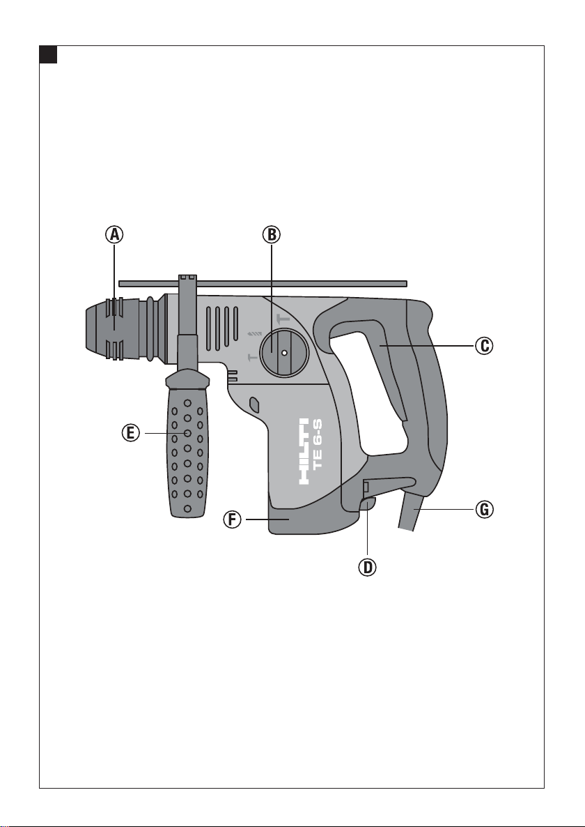
Operating controls and components
Chuck
Function selection switch
On/off switch
Forwards/reverse switch
Side handle with depth gauge
Connection for the dust removal module
Supply cord
1.1 Indication of danger
-CAUTION-
This word is used to draw attention to a potentially dangerous situation which could lead to minor personal injury
or damage to the equipment or other property.
1.2 Pictograms
Warning signs
General
warning
Obligation signs
Wear eye
protection
Symbols
Read the operat-
ing instructions
before use.
Warning:
electricity
Wear breathing
protection
Warning:
hot surface
Wear ear
protection
en
Wear protective
gloves
Contents Page
1. General information 1
2. Technical data 2
3. General safety rules 2
4. Specific safety rules and symbols 3
5. Functional description 4
6. Assembly 5
7. Operation 5
8. Care and maintenance 6
9. Accessories 7
10. Manufacturer's warranty – tools 8
11. Disposal 9
12. Troubleshooting 9
Printed: 07.07.2013 | Doc-Nr: PUB / 5071104 / 000 / 00
These numbers refer to the corresponding illustrations. The illustrations can be found on the fold-out cover pages. Keep these pages open while studying the operating instructions.
In these operating instructions, the designation "the tool"
always refers to the TE 6-S rotary hammer drill.
Location of identification data on the tool
The type designation and serial number can be found on
the type plate on the tool. Make a note of this data in your
operating instructions and always refer to it when making an enquir y to your Hilti representative or service
department.
Type:
Serial no.:
1
Page 9

2. Technical data
Tool TE6-S
Rated power 650 W
Rated voltage 120 V
en
Rated current input 5.4 A
Mains frequency 50–60 Hz
Weight of tool 2.8 kg (6.3 lbs)
Dimensions (l×w×h) 320×215×75 mm (12.5×8.5×3.0″)
No load speed 0–1160 r .p.m.
Hammering speed (full hammering action) 0–5100/min.
Hammering speed (reduced hammering action) 0–2700/min.
Single impact energy (full hammering action) 1.8 Nm (J)
Single impact energy (reduced hammering action) 0.6 Nm (J)
Drilling dia. range in concrete/masonry
(hammer drill bits) 4–24 mm dia. (3/16″–1″ dia.)
Drilling dia. range in wood (wood drill bits) 5–20 mm dia. (3/16″–3/4″ dia.)
Drilling dia. range in wood (hole saws) 25–68 mm dia. (1″–25/8″ dia.)
Drilling dia. range in metal (solid metal) 5–13 mm dia. (3/16″–1/2″ dia.)
Drilling dia. range in metal (sheet metal,
max. 2 mm [0.08″] thick) 5–22 mm dia. (3/16″–7/8″ dia.)
Drilling dia. range with thin-walled diamond core bits
(reduced hammering action) 25–68 mm dia. (1″–25/8″ dia.)
Drilling performance in medium-hard concrete (typical) up to 8 mm dia. (
up to 12 mm dia. (
up to 16 mm dia. (5/8″ dia.) = 49 cm3/min.
Mechanical slip clutch ●
Vibration-absorbing grip and side handle ●
Right of technical modification reserved
5
/16″ dia.) = 28 cm3/min.
1
/2″ dia.) = 45 cm3/min.
3. General safety rules
1. WARNING!
Read and understand all instructions.
Failure to follow all instructions listed below may
result in electric shock, fire and/or serious personal
injury.
SAVE THESE INSTRUCTIONS
2. Work Area
2.1 Keep your work area clean and well lit. Cluttered benches and dark areas invite accidents.
2.2 Do not operate power tools in explosive
atmospheres, such as in the presence of flammable liquids, gases, or dust. Power tools create
sparks which may ignite the dust or fumes.
2
Printed: 07.07.2013 | Doc-Nr: PUB / 5071104 / 000 / 00
2.3 Keep bystanders, children and visitors away
while operating a power tool. Distractions can
cause you to lose control.
3. Electrical Safety
3.1 Grounded tools must be plugged into an outlet
properly installed and grounded in accordance with
all codes and ordinances. Never remove the ground-
ing prong or modify the plug in any way. Do not use
any adaptor plugs. Check with a qualified electrican
if you are in doubt as to whether the outlet is proper-
ly grounded. If the tools should electrically malfunction
or break down, grounding provides a low resistance path
to carry electricity away from the user. Applicable only
to Class I (grounded) tools.
Page 10

3.2 Avoid body contact with grounded surfaces
such as pipes, radiators, ranges and refrigerators.
There is an increased risk of electric shock if your
body is grounded.
3.3 Don’t expose power tools to rain or wet condi-
tions. Water entering a power tool will increase the
risk of electric shock.
3.4 Do not abuse the cord. Never use the cord to
carry the tools or pull the plug from an outlet.
Keep cord away from heat, oil, sharp edges or
moving parts. Replace damaged cords immediately. Damaged cords increase the risk of electric
shock.
3.5 When operating a power tool outside, use an
outdoor extension cord marked «W-A» or «W».
These cords are rated for outdoor use and reduce
the risk of electric shock.
4. Personal Safety
4.1 Stay alert, watch what you are doing and use
common sense when operating a power tool. Do
not use a tool while tired or under the influence of
drugs, alcohol, or medication. A moment of inat-
tention while operating power tools may result in
serious personal injury.
4.2 Dress properly. Do not wear loose clothing or
jewelry. Contain long hair. Keep your hair, clothing, and gloves away from moving parts. Loose
clothes, jewelry, or long hair can be caught in moving parts.
4.3 Avoid accidental starting. Be sure switch is off
before plugging in. Carrying tools with your finger
on the switch or plugging in tools that have the
switch on invites accidents.
4.4 Remove adjusting keys or wrenches before
turning the tool on. A wrench or a key that is left
attached to a rotating part of the tool may result in
personal injury.
4.5 Do not overreach. Keep proper footing and
balance at all times. Proper footing and balance
enables better control of the tool in unexpected situations.
Holding the work by hand or against your body is
unstable and may lead to loss of control.
5.2 Do not force tool. Use the correct tool for your
application. The correct tool will do the job better
and safer at the rate for which it is designed.
5.3 Do not use tool if the switch does not turn it on
or off. Any tool that cannot be controlled with the
switch is dangerous and must be repaired.
5.4 Disconnect the plug from the power source be-
fore making any adjustments, changing acces-
sories, or storing the tool. Such preventive safety
measures reduce the risk of starting the tool acci-
dentally.
5.5 Store idle tools out of reach of children and
other untrained persons. Tools are dangerous in
the hands of untrained users.
5.6 Maintain tools with care. Keep cutting tools
sharp and clean. Properly maintained tools with
sharp cutting edges are less likely to bind and are
easier to control.
5.7 Check for misalignment or binding of moving
parts, breakage of parts and any other condition
that may affect the tools operation. If damaged,
have the tool serviced before using. Many acci-
dents are caused by poorly maintained tools.
5.8 Use only accessories that are recommended
by the manufacturer for your model. Accessories
that may be suitable for one tool may become haz-
ardous when used on another tool.
6. Service
6.1 Tool service must be performed only by quali-
fied repair personnel. Service or maintenance per-
formed by unqualified personnel could result in a risk
of injury.
6.2 When servicing a tool, use only identical
replacement parts. Follow instructions in the Main-
tenance section of this manual. Use of unauthorized
parts or failure to follow Maintenance Instructions
may create a risk of electric shock or injury.
en
4.6 Use safety equipment. Always wear eye protection. Dust mask, non-skid safety shoes, hard hat
or hearing protection must be used for appropriate
conditions.
5. Tool Use and Care
5.1 Use clamps or other practical way to secure
and support the workpiece to a stable platform.
Printed: 07.07.2013 | Doc-Nr: PUB / 5071104 / 000 / 00
4. Specific safety rules and symbols
4.1 Basic safety information
In addition to the safety precautions listed in the indi-
vidual sections of these operating instructions, the fol-
lowing points must be strictly observed at all times.
4.2 Correct use
The tools are designed for drilling in concrete, masonry,
plasterboard, wood and metal.
3
Page 11

The tools are designed for use on construction sites, in
workshops, for renovation, conversion and construction
work.
4.3 Incorrect use (misuse)
en
Operate the tool only when connected to a mains supply
with a voltage and frequency that complies with the information given on the name plate.
Manipulation or modification of the tool is not permissible.
Observe the information printed in the operating instructions concerning operation, care and maintenance.
4.4 State of the art
● The tool is designed and manufactured according to
the state of the art.
● The tool and its ancillary equipment may present hazards when used incorrectly by untrained personnel or
not as directed.
4.5 Proper arrangement and organisation of the
workplace
● Wear non-slip shoes and always work from a secure
stance.
● Avoid unfavourable body positions.
● Objects which could cause injury should be removed
from the working area.
● Always lead the supply cord and extension cord away
to the rear of the tool when working.
4.6 General hazards presented by the tool
● Always hold the tool securely with both hands.
● Keep the grip dry, clean and free from oil and grease.
● Hold the side handle tightly at its farthest end.
● Never leave the tool unsupervised.
4.6.1 Mechanical hazards
● When working outdoors, use only extension cords
that are approved and correspondingly marked for this
application.
Extension Cord Table
Volts Total Length of Cord inFeet
120 V 0–25 26– 50 51–100 101–150
240 V 0–50 51–100 101–200 201–300
Ampere Rating AWG
More Than Not More Than
0 6 18 16 16 14
610 18161412
10 12 16 16 14 12
12 16 14 12 Not recommended
● Do not touch the supply cord in the event of it becoming damaged while working. Unplug it from the mains
socket.
● Hold tool by insulated gripping surfaces when performing an operation where the cutting tool may contact hidden wiring or its own cord. Contact with a "live"
wire will make exposed metal parts of the tool "live" and
shock the operator.
4.7 Requirements to be met by users
● The tool is intended for professional use.
Symbols used on the tool:
V ............................ volts
~ ............................ alternating current
Hz ............................ hertz
A ............................ amperes
n
............................ no load speed
0
/min ............................ revolutions per minute
∅ ............................ diameter
k ............................ protective earth plug
4.8 Wear ear protectors when using the tool for
extended periods.
Prolonged exposure to high intensity noise can cause
hearing loss.
● Check that the insert tools used are compatible with
the chuck system and that they are secured in the chuck
correctly.
4.6.2 Electrical hazards
● Concealed electric cables, gas and water pipes present a serious hazard if damaged while working. Accordingly, check the working area in advance, e.g. using a
metal detector. Avoid body contact with earthed objects
such as pipes or radiators. External metal parts of the
tool could become live when, for example, a live cable is
drilled into inadvertently.
4
Printed: 07.07.2013 | Doc-Nr: PUB / 5071104 / 000 / 00
5. Functional description
The TE 6-S rotary hammer drills with selectable pneumatic hammering mechanism are electrically-powered
tools for drilling in concrete, masonry, plasterboard (drywall), wood, plastics and metal.
The tools are designed for professional use.
Chuck
– with rotary locking action
– Interface for TE-C chuck and keyless chuck
Switches
– Speed-control switch
– Function selection switch
Page 12

TE6-S: 3 drilling functions
– Reversing switch (switch for forwards/reverse rota-
tion)
Side handle
– Privoting side handle with depth gauge
Lubrication
– The gearing section and hammering mechanism feature permanent grease lubrication.
The items supplied as standard equipment include:
– Rotary hammer drill
– Privoting side handle with depth gauge
– Grease
– Operating instructions
– T oolbox
– DRS dust-removal module (with version in the pro-
fessional toolbox)
– Cleaning cloth
6. Assembly
7. Operation
The side handle must always be fitted when the tool is in
use.
Use clamps or a vice to secure loose workpieces.
If extension cords are used: Only extension cords of a
type approved for the intended use and of adequate cross
section may be used. Failure to observe this point may
result in reduced performance of the tool and overheating
of the cord. Damaged extension cords must be replaced.
At low temperatures: The tool requires to reach a minimum operating temperature before the hammering mechanism begins to operate. Switch on the tool and position
the tip of the drill bit on the work surface. While the tool
is running, apply light pressure briefly and repeatedly
until the hammering mechanism begins to operate.
-CAUTION-
en
The tool must not be connected to the electric mains supply.
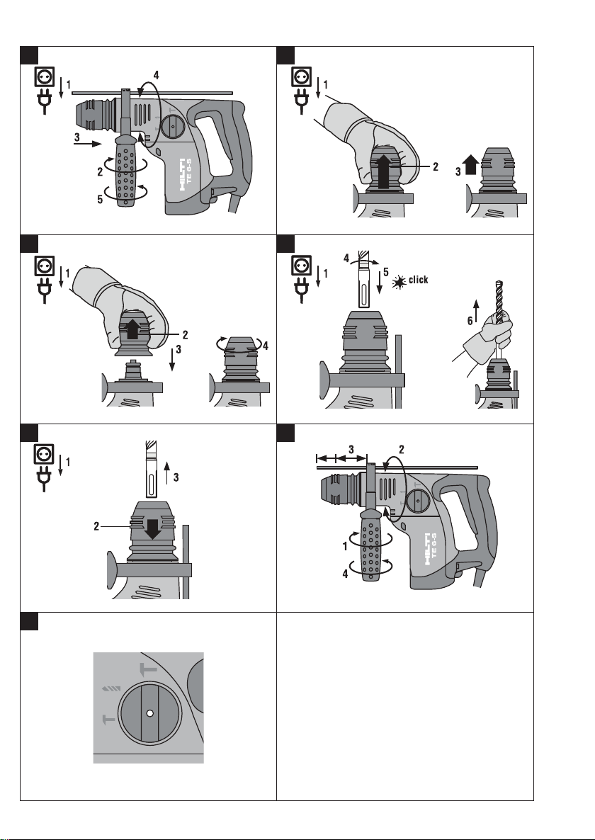
6.1 Fit the side handle
1. Release the side handle clamp by turning the side handle grip.
2. Slide the side handle / clamping band over the chuck
onto the housing (clamping groove).
3. Turn the side handle into the desired position.
4. Secure the side handle by twisting its grip.
6.2 Removing the chuck
CAUTION
Remove the depth gauge from the side handle and the
insert tool from the chuck in order to avoid injury.
1. Disconnect the supply cord plug from the power
outlet.
2. Pull the chuck sleeve forward and hold it securely.
3. Remove the chuck by pulling it away from the power tool.
6.3 Fitting the chuck
CAUTION
Remove the depth gauge from the side handle and the
insert tool from the chuck in order to avoid injury.
1. Disconnect the supply cord plug from the power
outlet.
2. Grip the chuck sleeve, pull it forward and hold it
securely in this position.
3. Slide the chuck onto the guide tube from the front
and then release the sleeve.
4. Rotate the chuck until it is heard to engage.
■ The insert tool may become hot during use.
■ You may burn your hands.
■ Wear protective gloves when chang-
ing insert tools.
7.1 Fitting the insert tool
CAUTION
Wear protective gloves when changing the insert tool.
1. Disconnect the supply cord plug from the power outlet.
2. Check that the connection end of the insert tool is clean
and lightly greased. Clean it and grease it if necessary.
3. Check that the sealing lip of the dust shield is clean and
in good condition. Clean the dust shield if necessary
or replace it if the sealing lip is found to be damaged
(please refer to the “Care and maintenance” section).
4. Push the insert tool into the chuck and rotate it while
applying slight pressure until it engages in the guide
grooves.
5. Push the insert tool further into the chuck until it is
heard to engage.
6. Check that the insert tool has engaged correctly by
pulling it.
7.2 Removing the insert tool
CAUTION
Wear protective gloves when changing insert tools as
the insert tool will get hot during use.
1. Disconnect the supply cord plug from the power outlet.
2. Open the chuck by pulling back the chuck release
sleeve.
3. Pull the insert tool out of the chuck.
Printed: 07.07.2013 | Doc-Nr: PUB / 5071104 / 000 / 00
5
Page 13

7.3 Adjusting the depth gauge
1. Open the side handle clamp by turning the grip.
2. Pivot the side handle into the desired position.
3. Adjust the depth gauge to the desired drilling depth
"X".
4. Secure the side handle by turning the side handle grip.
en
7.4 Hammer drilling with full hammering action
-CAUTION-
■ The material may splinter during drilling.
■ Splintering material may injure parts
of the body and the eyes.
■ Wear eye protection, protective gloves
and, if a dust removal system is not
used, also wear breathing protection.
7.6 Drilling without hammering action
1. Plug in the supply cord.
2. Turn the switch to the "( )" position. When the
switch is in this position, only the rotary action is transferred to the insert tool.
3. Press the control switch slowly (drill at a slow speed
until the drill bit has become centred in the hole).
4. Press the control switch as far as it will go when you
wish to continue at full speed.
7.7 Forwards / reverse rotation
1. Turn the lever to the (L ) or position (R ).
8. Care and maintenance
Unplug the supply cord.
-CAUTION-
■ The tool and the drilling operation emit
noise.
■ Excessive noise may damage the hearing.
■ Wear ear protection.
1. Plug in the supply cord.
2. Turn the switch to the "( )" position.
3. Position the tip of the drill bit where the hole is to be
drilled.
4. Press the control switch slowly (drill at a slow speed
until the drill bit has become centred in the hole).
5. Press the control switch as far as it will go when you
wish to continue at full speed.
6. Do not apply excessive pressure as this will not increase
hammering power. Lower pressure increases the life
of the insert tool.
7. When drilling a through hole, avoid spalling by reducing speed shortly before breaking through.
7.5 Hammer drilling with reduced hammering power
1. Plug in the supply cord.
2. Turn the switch to the ( ) position.
3. Position the tip of the drill bit where the hole is to be
drilled.
4. Press the control switch slowly (drill at a slow speed
until the drill bit has become centred in the hole).
5. Press the control switch as far as it will go when you
wish to continue at full speed.
6. When working on critical materials, spalling can be
reduced by using TE-C drill bits in new condition in
conjunction with reduced hammering action.
8.1 Care of insert tools
Remove any dirt adhering to the surface of the insert
tools and protect them from corrosion by rubbing them
with an oily cloth from time to time.
8.2 Care of the tool
The outer casing of the tool is manufactured from impactresistant plastic. The grip section is manufactured from
synthetic rubber.
The ventilation slots must be unobstructed and kept clean
atalltimes.Useadrybrushtocleantheventilationslots
carefully. Do not permit foreign objects to enter the interior of the tool. Use a slightly damp cloth to clean the outside of the tool at regular intervals. Do not use a spray,
steam-cleaning system or running water for cleaning.
This may negatively affect the electrical safety of the tool.
Always keep the grip sections of the tool free from oil
and grease. Do not use cleaning agents or polishes, etc.,
containing silicone.
8.3 Maintenance
Check all external parts of the tool for damage at regular
intervals and check that all controls operate faultlessly.
Do not operate the tool when parts are damaged or when
the controls do not operate faultlessly. If necessary, have
the tool repaired at a Hilti service centre.
Electrical parts of the tool may be repaired only by trained
electrical specialists.
8.4 Checking the tool after care and maintenance
After all care and maintenance work, the tool must be
checked to ensure that all safety equipment is fitted and
that it operates faultlessly.
6
Printed: 07.07.2013 | Doc-Nr: PUB / 5071104 / 000 / 00
Page 14

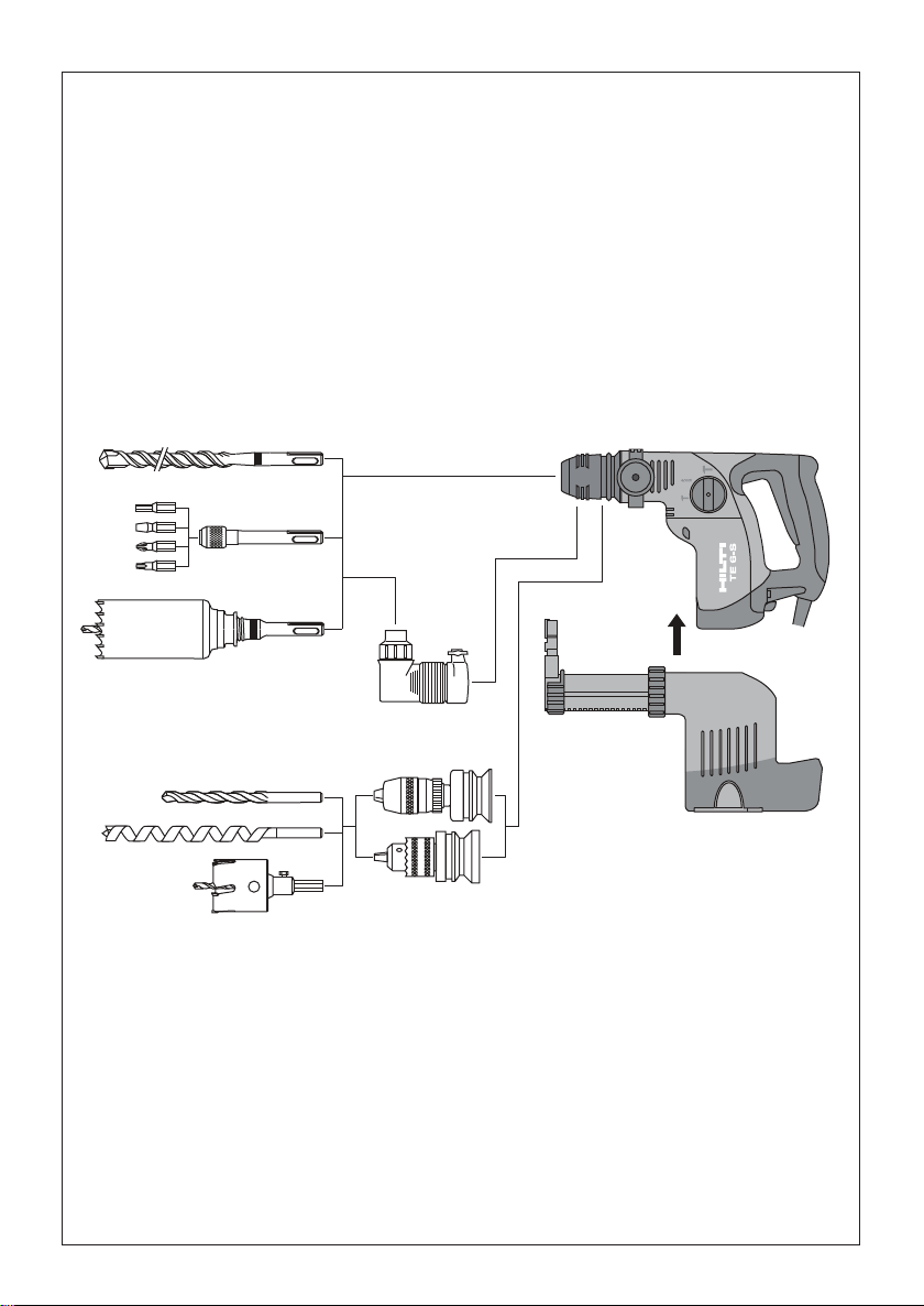
9. Insert tools and accessories
TE-C chuck ●
TE-C angular chuck ●
TE-AC 1 angular chuck ●
Hammer drill bits 4–24 mm dia. (3/16″–1″ dia.)
Bit holder ●
Thin-barrel core bits 25–68 mm dia. (1″–25/8″ dia.)
Chisels (TE6-C) SM, FM, KM, SPM
Keyless chuck (quick release) ●
Drill bits for wood 5–20 mm dia. (3/16″–3/4″ dia.)
Drill bits for metal 5–13 mm dia. (3/16″–1/2″ dia.)
Stepped (stop) drill bits 5–22 mm dia. (3/16″–5/8″ dia.)
Hole saws 25–68 mm dia. (1″–25/8″ dia.)
DRS dust removal module ●
9.1 DRS dust removal module
9.1.1 General information
Location of identification data on the tool
The type designation and serial number can be found on the type plate on the tool. Make a note of this data in your
operating instructions and always refer to it when making an enquiry to your Hilti representative or service department.
Type: Serial no.:
9.1.2 Description
The DRS dust removal module is an accessory for the TE-6 rotary hammer drill. It can be attached to the rotary hammer
drill quickly and easily. The dust removal module is not suitable for chiselling work or for rotary drilling in metal.
en
9.1.3 Technical data
Power input Max. 60 W
Suction performance 500 l/min
Weight 0.9 kg (2.03 lbs)
Maximum effective stroke 105 mm (4.1″)
TE-C hammer drill bit diameter range: 4–16 mm dia. (3/16″–5/8″ dia.)
Drill bit working length 50–100 mm (2–4″)
Contact pressure 15–25 N
Dust container capacity
1
6mm(
/4″) dia. / 28 mm (1.1″) deep 130 holes
5
8mm(
/16″) dia. / 30 mm (1.2″) deep 75 holes
12 mm (1/2″) dia. / 50 mm (2″) deep 20 holes
Dust container regeneration cycles Up to 100 cycles
Extraction head 4–16 mm dia. (3/16″–5/8″ dia.)
Extraction fan, dust container with folded filter, depth gauge, length stop, plug-type connection
9.1.4 Before use
Attaching the dust removal module
The extraction fan incorporated in the dust removal module is driven by the motor of the rotary hammer drill by
way of a plug-type coupling. The teeth on the rotor shaft
(1) mesh with the teeth on the sleeve (2) of the dust
removal module drive shaft.
Printed: 07.07.2013 | Doc-Nr: PUB / 5071104 / 000 / 00
1. Unplug the supply cord.
2. Push the dust removal module along the guide (3) on
the rotary hammer drill until it engages securely in
place.
Removing the dust module
1. Unplug the supply cord.
2. Press the release latch (4) and hold it in this position.
7
Page 15

3. Pull the dust module downwards away from the rotary
hammer drill.
9.1.5 Operation
Length adjustment (setting the stroke)
The stroke is normally set to TE-C drill bit I
(6″). This corresponds to an effective working length of
en
100 mm. The stroke must be adjusted if shorter drill bits
are used.
1. Open (A) the locking ring (5).
2. With the drill bit fitted in the chuck, press the tool
against the wall until the tip of the drill bit comes into
contact with the wall (C).
3. Close (B) the locking ring (5).
Setting the drilling depth (depth gauge)
1. Open (D) the end stop (6).
2. Slide the end stop to the desired drilling depth (F).
3. Close (E) the end stop (6).
When holes are to be drilled to a precise depth, e.g. for
setting anchors, the hole depth must be checked by drilling
test holes.
Changing the suction head
1. Pull back the rib (G) on the rear of the suction head
(7).
2. Pull the old suction head upwards out of the guide (H).
3. Press the new suction head into the guide until it
engages.
Emptying the dust container
1. Hold the tool horizontally and allow it to run for a short
time. This will cause any remaining dust particles in
the dust removal module to be sucked into the dust
container.
2. Press the button and hold it in this position (K).
3. Pull the dust container (8) downwards out of the dust
removal module (L).
4. Empty the dust container by tapping it lightly.
5. Slide the empty dust container into the dust module
from below until it engages in position. If you are inserting a new dust container, remove the protective cover before inserting it.
9.1.6 Care and maintenance
Use only compressed air and a cloth to clean the dust
removal module. Do not use water, oil, grease or cleaning agents.
t =150mm
10. Manufacturer's warranty – tools
Hilti warrants that the tool supplied is free of defects
in material and workmanship. This warranty is valid so
long as the tool is operated and handled correctly,
cleaned and serviced properly and in accordance with
the Hilti Operating Instructions, and the technical system is maintained. This means that only original Hilti
consumables, components and spare parts may be
used in the tool.
This warranty provides the free-of-charge repair or
replacement of defective parts only over the entire lifespan of the tool. Parts requiring repair or replacement
as a result of normal wear and tear are not covered by
this warranty.
Additional claims are excluded, unless stringent
national rules prohibit such exclusion. In particular,
Hilti is not obligated for direct, indirect, incidental
or consequential damages, losses or expenses in
connection with, or by reason of, the use of, or inability to use the tool for any purpose. Implied warranties
of merchantability or fitness for a particular purpose
are specifically excluded.
For repair or replacement, send tool or related parts
immediately upon discovery of the defect to the address
of the local Hilti marketing organization provided.
This constitutes Hilti's entire obligation with regard to
warranty and supersedes all prior or contemporaneous comments and oral or written agreements concerning warranties.
8
Printed: 07.07.2013 | Doc-Nr: PUB / 5071104 / 000 / 00
Page 16

Hilti Corporation
LI-9494 Schaan
Tel.:+423 / 234 21 11
Fax: +423/2342965
www.hilti.com
Hilti = registered trademark of Hilti Corp., Schaan W 2628 0809 10-Pos. 3 GE 1 Printed in China © 2009
Right of technical and programme changes reserved S. E. & O.
Printed: 07.07.2013 | Doc-Nr: PUB / 5071104 / 000 / 00
374434/E
*374434*
374434
 Loading...