

Page 1

SF 180-A
*375007*
375007
Operating instructions 9–16
en
Page 2
1
7 4 8 1 5 3
2
9
6
Page 3

2
3
4
5
1-13
13
57911
L
STOP
R
2
1
Page 4
6
7
Page 5
9
It is essential that the operating
instructions are read before the
tool is operated for the first time.
Always keep these operating
instructions together with the tool.
Ensure that the operating instructions are with the tool when it is
given to other persons.
SF180-A hammer drill driver
1. General information
1.1 Indication of danger
-CAUTION-
Used to draw attention to a potentially dangerous situation which could lead to minor personal injury or damage to the equipment or other property.
-NOTE-
Used to draw attention to an instruction or other useful
information. Not used for dangerous situations or where
damage to the equipment or property could occur.
1.2 Pictograms
Contents Page
1. General information 9
2. Description 10
3. Tools and accessories 10
4. Technical data 10
5. Safety precautions 11
6. Before use 12
7. Operation 13
8. Care and maintenance 14
9. Troubleshooting 15
10. Disposal 16
11. Warranty 16
12. Declaration of conformity See cover
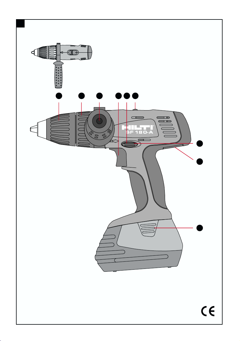
Operating controls and parts
Control switch
(with electronic speed control)
Forward / reverse switch
Gear selector switch
Torque clutch setting ring
Motor brake
Battery release buttons (2)
Quick release clutch
Side handle
Rating plate
Warning signs
General
warning
Warning:
electricity
Warning:
hot surface
Obligation signs
Symbols
Wear
eye
protection
Wear
ear protection
Read the operating
instructions before use.
Wear
breathing
protection
Warning:
caustic
substances
Wear
a safety
helmet
Wear
protective
gloves
Return waste material
for recycling.
Do not dispose of
batteries with general
refuse.
These numbers refer to the corresponding illustrations. The illustrations can be found on the fold-out cover pages. Keep these pages open while studying the operating instructions. In these operating instructions, the
SF180-A hammer drill driver with battery fitted is referred
to as "the tool".
Location of identification data on the tool
The type designation, item number, year of manufacture
and technical status can be found on the rating plate on
the tool. The serial number is located on the left side of
the motor housing. Make a note of this data in your operating instructions and always refer to it when making an
V = volts
–––
- - -
= direct current
n
o = no load speed
/min = revolutions per minute
j = hammer drilling
= rotation only
Page 6

4. T echnical data
Tool SF180-A
Rated voltage 18 V
–––
- - -
Weight of tool including battery and chuck 2.6 kg
Dimensions (L×H×W) 251×274×83 mm
Speed 1
st
gear: 0– 460 r.p.m.
2ndgear: 0–1600 r.p.m.
Chuck / clamping dia. range (Quick-release chuck) 1.6–13 mm
Torque Max. 31 Nm (at drilling setting)
Torque adjustment 2–12 Nm (in 13 increments)
Speed control Electronic control switch
Forward / reverse Electrical switch with interlock to prevent activation
when running
Spindle lock When control switch is in the “off” position
Motor brake By way of the control switch
Gearing section sealed to prevent entry of dust and with permanent lubrication (maintenance-free)
Noise and vibration information (measured in accordance with EN 50260):
Typical A-weighted noise power level: 99.7 dB(A)
Typical A-weighted noise pressure level: 88.7 dB(A)
Typical weighted vibration at the grips: 9.2 m/s
2
Battery SFB180 SFB185
Rated voltage 18 V
–––
- - -
18 V
–––
- - -
Battery capacity 18 V×2.0 Ah = 36 Wh 18 V×3.0 Ah = 54 Wh
Weight 1.15 kg 1.22 kg
Temperature monitoring yes yes
Type of cell Nickel-cadmium Nickel-metal hydride
SUB C type SUB C type
No. of cells 15 15
Right of technical changes reserved
10
enquiry to your Hilti representative or service department.
Type: Serial no.:
2. Description
The SF180-A is a battery-powered hammer drill driver
for professional use. The tool is suitable for use by right
or left-handed persons. The ergonomically designed rubber-padded grip reduces fatigue and is designed to provide a secure hold.
The items supplied include: Electric tool with side handle,
two SFB180 or SFB185 batteries, SFC7/18H or SFC7/18
charger, rigid carrying case.
Important features of the tool
– Vibration-absorbing grip (rubber-padded)
– Smooth speed control
– Gearing and clutch with permanent lubrication
(grease)
– Automatic cut-out carbon brushes
– Forward / reverse rotation
3. Accessories
Magnetic bit holder, long S-BHP 75M
Philips bit Phillips Nr. 2
Charger SFC 7/18
Charger SFC 7/18 H
Charger TCU 7/36
Battery SFB 180 or SFB 185
Toolbox
Belt adaptor
Page 7

11
5. Safety precautions
5.1 Basic information concerning safety
In addition to the information relevant to safety given in
each of the sections of these operating instructions, the
following points must be strictly observed at all times.
CAUTION!
To reduce the risk of fire, battery leakage and personal
injury, the following basic safety precautions must be
observed when battery-powered tools are used:
Read all these instructions before operating this product
and save these instructions.
5.2 Correct use
The SF 180-A is a battery-powered hammer drill driver
for the following applications:
– Driving and removing screws
– Drilling in steel and wood
– Hammer drilling in masonry and light concrete
The working environment may be on a construction site
or in a workshop and may consist of renovation, conversion or new building work.
Main applications
Spax screws in softwood /
chipboard 10×80 mm *
Screws in plastic anchors HRD-U 10/50 120 *
Self-drilling screws S-MD 01 5.5×19 mm **
Drilling in softwood /
chipboard 30 mm diameter **
Hole saws 102 mm diameter *
HSS drill bits 13 mm diameter **
* Speed 1 (low), ** Speed 2 (high)
● Modification or manipulation of the tool other than
described in these operating instructions is not permissible.
●To avoid the risk of injury, use only original Hilti acces sories and additional equipment.
●Observe the information printed in the operating instructions concerning operation, care and maintenance.
●The tool and its ancillary equipment may present hazards when used incorrectly by untrained personnel or
when used not as directed.
5.3 Take the necessary precautions to make the workplace safe
●Wear non-slip shoes or boots and always ensure that
you have a secure stance.
●Avoid unfavorable body positions.
●Ensure that the workplace is well lit.
●Ensure that the workplace is well ventilated.
●Objects which could cause injury should be removed
from the working area.
●When working, keep other persons, particularly children, outside the range of the tool.
●Do not wear loose clothing, loose long hair or jewelry as these can become caught up in moving parts. Wear
suitable headgear if you have long hair.
●Concealed electric cables or gas and water pipes present a serious hazard if damaged while you are working.
Accordingly, check the area in which you are working
beforehand (e.g. using a metal detector). Avoid contact
between your body and earthed / grounded objects, such
as pipes or radiators. External metal parts of the tool may
become live, for example, when an electric cable is drilled
into inadvertently.
●Do not expose the tool to rain or snow and do not use
it in damp or wet areas or where there is a risk of explosion. It is safer than using your hand and it frees both
hands to operate the tool.
●Use a vice or clamp to secure loose workpieces.
●The tool is for hand-held use only.
5.4 General safety precautions
● Operate the tool only as directed and only when it is
in faultless condition.
●Use only insert tools which are approved for use with
the electric tool.
●Keep the grips dry, clean and free from oil and grease.
●Do not touch the chuck while it is rotating.
●Never leave the tool unsupervised.
●Avoid unintentional starting. Do not carry the tool with
your finger on the on/off switch. Switch the tool off completely before transporting it (forward / reverse switch
in middle position).
● Switch the tool on only after bringing it into position
at the workpiece.
● Use only the original accessories or ancillary equipment listed in the operating instructions. Use of other
insert tools or accessories may present a risk of personal
injury.
●Do not overload the tool. It will work more efficiently
and more safely within its intended performance range.
● Disconnect the tool from its battery pack when the
tool is not in use, during pauses between work, before
maintenance, when changing bits and during transport.
● When not in use, the tool and battery pack must be
stored separately in a dry place, locked up or out or reach
of children.
●Take care of your insert tools. You will be able to work
more efficiently and more safely if the insert tools are
kept sharp and clean. Observe instructions on care and
maintenance and on changing insert tools.
● Do not insert wires or other similar objects into the
ventilation slots.
Page 8

12
5.4.1 Mechanical hazards
●Follow the instructions concerning care and maintenance.
● Check that the insert tools used are compatible with
the chuck system and that they are secured in the chuck
or gear housing correctly.
● Check that moving parts function faultlessly and that
they are not sticking or damaged. All parts must be correctly fitted and fulfil all requirements in order to ensure
that the tool operates faultlessly.
● Use only original Hilti insert tools.
5.4.2 Electrical hazards
●Check the condition of the tool. Do not operate the tool
if it is found to be damaged, if it is not complete or if its
controls cannot be operated faultlessly.
●Damaged switches must be replaced at a Hilti service
center. Do not use the tool if it cannot be switched off
and on properly.
●The tool may be repaired by trained electrical specialists only (Hilti service) using original Hilti spare parts.
Failure to observe this point may present considerable
risk to the user.
●Never operate the tool when it is dirty or wet.
●Ensure that the outer surfaces of the battery are clean
and dry before inserting it in the corresponding charger.
●Use only the batteries listed in these operating instructions (see section 6).
● Avoid short circuiting the battery terminals. A short
circuit may cause a fire.
●Check that the battery is securely attached to the tool.
A falling battery could injure you or other persons.
●Batteries that have reached the end of their life must
be disposed of safely (see section 10).
● Ensure that batteries are charged using the correct
charger recommended by the manufacturer . Incorrect
use may result in a risk of electric shock, overheating or
leaking of corrosive liquid from the battery.
5.4.3 Thermal hazards
●The insert tool may become hot during use. You should
therefore wear protective gloves when changing insert
tools.
5.4.3 Liquids
●A caustic liquid may leak from defective batteries. Avoid
contact with this liquid. In the event of contact with the
skin, wash the area affected with soap and plenty of water .
Should the liquid come into contact with the eyes, flush
the eyes with water immediately and subsequently consult a doctor.
5.5 Requirements to be met by users
●The tool is intended for professional use.
●The tool may be operated, serviced and repaired only
by authorized, trained personnel. This personnel must
be informed of any special hazards that may be encountered.
● Always concentrate on the job you are doing. Proceed
carefully and do not use the tool if your full attention is
not on the job.
5.6 Personal protective equipment
● The operator and other persons in the immediate vicinity must always wear eye protection, ear protection and
breathing protection while the tool is in use.
6. Before use
1. It is essential that the safety precautions printed in
these operating instructions are read and observed.
2. A new battery must be charged correctly for the first
time before use:
– charged normally for 24 hours with the SFC 7/8 H
charger, or
– charged for 12 hours using the conditioning func-
tion of the SFC 7/18 or TCU 7/36 charger
This will ensure that the cells form correctly. Incorrect
initial charging may have a permanent, negative effect
on battery capacity.
-NOTE-
– The tool may be used only with SFB 180 or SFB 185
batteries.
– Battery performance drops at low temperatures.
– Batteries should be stored at room temperature.
– Never store batteries where they are exposed to the
heat of the sun, on a radiator, behind a motor vehicle
windscreen or at a window.
– Never use the battery until the cells become fully dis-
charged. Change to the second battery as soon as a
drop in performance is noticed and recharge the bat-
tery immediately so that it is ready for re-use.
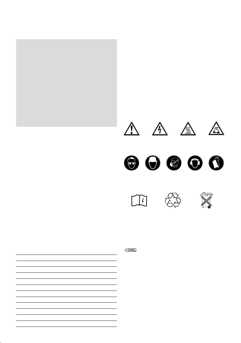
– Use bits with a standard
1
/4″ hex. shank.
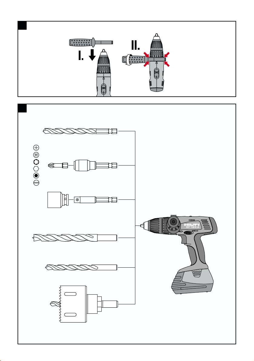
6.1 Fitting the side handle
1. Open the side handle clamping band by turning the
handle.
Page 9

7.4 Hammer drilling
Turn the torque clutch setting ring to the hammer drilling
symbol.
7.5 Drilling
Turn the torque clutch setting ring to the drilling sym bol.
-CAUTION-
A high torque is experienced if the insert tool sticks while
drilling with large-diameter drill bits and hole saws.
Accordingly, use the side handle and hold the tool with
both hands (one hand on the grip and one hand on the
side handle).
7.6 Switching on and off
Should a sticking drill bit cause the motor to stall for
longer than 2–3 seconds, the tool must be switched off
in order to avoid damage to it.
1. Use the forward / reverse switch to select the direc-
tion of rotation.
2. The speed of the tool can be controlled smoothly
between zero and maximum by pressing the on / off
switch slowly.
7.7 Removing the battery (2-finger operation)
1. Press in both release buttons.
2. Pull the battery downwards out of the tool.
7.8 Fitting the battery
Use only Hilti SFB 180 or SFB 185 batteries.
Push the battery into the tool from below until it is heard
to engage.
7.9 Charging the battery
The battery cannot be charged through the belt adaptor.
Use only the Hilti SFC7/18H, SFC7/18 or TCU7/36 charger.
Incorrect use may lead to electric shocks, overheating
of the battery or leakage of a caustic liquid from the battery.
Read the operating instructions for the charger before
beginning charging.
7.10 Changing the bit
13
-CAUTION-
■ Noise is emitted by the tool and the
screwdriving / drilling / hammer
drilling procedure.
■ Excessive noise may damage the
hearing.
■ Wear ear protection.
2. Slide the side handle clamping band over the chuck
and onto the tool.
3. Pivot the side handle into the desired position.
4. Secure the side handle by turning the handle.
7. Operation
-CAUTION-
■ The screwdriving procedure may
cause the material to splinter .
■ Splintering material may cause injury
to the body, respiratory passages
and the eyes.
■ Wear eye protection, breathing protection and a safety helmet.
7.1 Setting forwards or reverse rotation
The direction of rotation of the driving spindle can be
selected by operating the forward / reverse push switch.
An interlock prevents operation of the switch while the
motor is running. When in the middle position, the on /
off switch is locked.
– Push the forward / reverse switch to the right (tool in
the working position) = reverse.
– Push the forward / reverse switch to the left (tool in
the working position) = forwards.
7.2 Setting the speed
(2-speed gear selector switch)
-CAUTION-
Operate the gear selector switch only when rotation has
stopped.
Select position 1 for a speed range of 0–460 r .p.m. or
position 2 for a speed range of 0–1600 r.p.m.
7.3 Screwdriving
Set the desired direction of rotation by way of the forward / reverse switch.
7.3.1 Torque setting
Set the torque by turning the torque clutch setting ring
to the desired torque setting (1–13).
-CAUTION-
■ The insert tool may become hot during use.
■ There is a risk of burning the hands.
■ Wear protective gloves when chang-
ing insert tools.
Page 10

14
8. Care and maintenance
8.1 Care of insert tools
Remove any dirt adhering to the surface of the insert
tools and protect them from corrosion by rubbing them
with an oily cloth from time to time.
8.2 Care of the tool
Before cleaning, remove the battery from the tool in order
to prevent inadvertent starting.
The outer casing of the tool is manufactured from impactresistant plastic. The grip comprises a synthetic rubber
section.
The ventilation slots must be unobstructed and kept clean
at all times. Use a dry brush to clean the ventilation slots
carefully. Do not permit foreign objects to enter the inte rior of the tool. Use a slightly damp cloth to clean the outside of the tool at regular intervals. Do not use a spray,
steam-cleaning system or running water for cleaning.
This may negatively affect the electrical safety of the tool.
Always keep the grip sections of the tool free from oil
and grease. Do not use cleaning agents or polishes, etc.
containing silicone.
8.3 Maintenance
Check all external parts of the tool for damage at regular
intervals and check that all controls operate faultlessly.
Do not operate the tool when parts are damaged or when
the controls do not operate faultlessly. If necessary , have
the tool repaired at a Hilti service center.
Electrical parts of the tool may be repaired only by trained
electrical specialists.
8.4 Care of the battery
Keep the electrical contacts free from dust, oil and grease.
If necessary, use a clean cloth to clean the contact surfaces.
Do not continue to operate the tool until the battery is
completely discharged as this may damage the battery
cells. Recharge the battery as soon as a drop in performance is noticed.
At monthly intervals or, at the latest, when battery capacity drops significantly, the battery should be conditioned
as follows:
– by charging with the SFC 7/8 H charger for 24 hours
in normal charging mode, or
– by charging with the SFC 7/18 or TCU 7/36 charger for
12 hours in conditioning mode.
If, after conditioning, battery capacity is still unsatisfactory, we recommend returning the battery to Hilti for diagnosis.
8.5 Checking the tool after care and maintenance
After carrying out care and maintenance work on the tool,
check that all protective and safety devices are fitted and
that they function faultlessly.
Page 11

15
9. T roubleshooting
Fault Possible cause Remedy
Tool doesn‘t run Battery is discharged or not correctly Refit the battery. It must be heard
fitted to engage with an audible "click".
Charge the battery if necessary.
Electrical fault Remove the battery and contact
your nearest Hilti service center.
Tool runs too fast / too slow Speed selector in wrong position Move the speed selector switch to
the desired position.
No hammering action Tool set to the wrong mode Set the tool to hammering
mode.
Clutch releases while drilling Tool set to screwdriving mode Set the tool to drilling mode.
On / off switch cannot be pressed Forward / reverse switch is set to Move the forward / reverse switch
middle position to the left/right.
Speed suddenly drops The battery is almost exhausted. Stop working with the exhausted
battery and charge it fully.
Battery becomes discharged Battery condition is not optimal. Charge the battery using condi-
faster than usual tioning mode (see battery charger
operating instructions).
Battery does not engage with an Dirt on battery locking mechanism Clean battery locking mechanism
audible "click" and refit the battery. Contact your
nearest Hilti service center if the
problem persists.
Tool or battery overheats Electrical fault Switch off the tool immediately.
Remove the battery and contact
your nearest Hilti service center.
Overload due to exceeding application Select the right tool for the applilimit cation.
Drill bit or screw gets stuck Release the drill bit or screw .
Drill bit or screwdriving bit slips Chuck not tightened correctly Tighten the chuck securely by
in the chuck applying reasonable force.
Page 12

16
11. Warranty
Hilti warrants that the tool supplied is free of defects in
material and workmanship. This warranty is valid as long
as the tool is operated and handled correctly, cleaned
and serviced properly and in accordance with the Hilti
Operating Instructions, all warranty claims are made
within 12 months from the date of the sale (invoice date),
and the technical system is maintained. This means that
only original Hilti consumables, components and spare
parts may be used in the tool.
This warranty provides the free-of-charge repair or
replacement of defective parts only. Parts requiring repair
or replacement as a result of normal wear and tear are
not covered by this warranty.
Additional claims are excluded, unless stringent
national rules prohibit such exclusion. In particular,
Hilti is not obligated for direct, indirect, incidental or
10. Disposal
Return waste material for recycling.
Most of the materials from which Hilti power tools are manufactured can be recycled. The materials must be correctly separated before they can be recycled. In many countries, Hilti has already made arrangements for taking back
your old electric tools for recycling. Please ask your Hilti customer service department or Hilti sales representative
for further information.
Should you wish to return the electric tool yourself to a disposal facility for recycling, proceed as follows: Dismantle the tool as far as possible without the need for special tools. Use absorbent paper to wipe greasy parts clean and
collect any grease that runs out. This paper should also be disposed of correctly. On no account should grease be
allowed to enter the waste water system or find its way into the ground.
Separate the individual parts as follows:
Part / assembly Main material Recycling
Toolbox Plastic Plastics recycling
Outer casing Plastic / synthetic rubber Plastics recycling
Electronic switch Various Electronics scrap
Motor Steel, copper Scrap metal
Gearing parts Steel Scrap metal
Battery Nickel-cadmium *
Nickel-metal hydride
Screws, small parts Steel Scrap metal
* Dispose of the battery in accordance with national regulations or return used batteries to Hilti for recycling.
consequential damages, losses or expenses in connection with, or by reason of, the use of, or inability
to use the tool for any purpose. Implied warranties of
merchantability or fitness for a particular purpose are
specifically excluded.
For repair or replacement, send tool and/or related parts
immediately upon discovery of the defect to the address
of the local Hilti marketing organization provided.
This constitutes Hilti’s entire obligation with regard to
warranty and supersedes all prior or contemporaneous
comments and oral or written agreements concerning
warranties.
Page 13

12. EC declaration of conformity
Designation: Hammer drill driver
Type designation: SF 180-A
Year of design: 2002
We declare, on our sole responsibility, that this product
complies with the following directives and standards:
98/37/EC, 89/336/EEC, 91/157/EEC, 93/86/EEC, EN
50260-1, EN 50260-2, EN 55014-1, EN 55014-2
12. Konformitätserklärung
Bezeichnung: Schlagbohrschrauber
Typenbezeichnung: SF180-A
Konstruktionsjahr: 2002
Wir erklären in alleiniger Verantwortung, dass dieses
Produkt mit den folgenden Richtlinien und Normen
übereinstimmt: 98/37/EG, 89/336/EWG, 91/157/EWG,
93/86/EWG, EN 50260-1, EN 50260-2, EN 55014-1,
EN 55014-2
12. Déclaration de conformité CE
Désignation: Visseuse-perceuse à percussion
Modèle: SF 180-A
Année de conception: 2002
Nous déclarons sous notre seule et unique responsabilité que ce produit est conforme aux directives et
normes suivantes: 98/37/CE, 89/336/CEE, 91/157/CEE,
93/86/CEE, EN 50260-1, EN 50260-2, EN 55014-1, EN
55014-2
12. EG-conformiteitsverklaring
Product: Slagboorschroefmachine
Type: SF 180-A
Bouwjaar: 2002
Wij verklaren, op onze eigen verantwoording, dat dit
product voldoet aan de volgende richtlijnen en normen:
98/37/EG, 89/336/EEG, 91/157/EEG, 93/86/EEG, EN
50260-1, EN 50260-2, EN 55014-1, EN 55014-2
12. EU konformitetserklæring
Betegnelse: Bore-/skruemaskine
Typebetegnelse: SF180-A
Konstruktionsår: 2002
Vi påtager os det fulde ansvar for, at dette produkt er i
overensstemmelse med følgende normer eller
98/37/EF, 89/336/EØF, 91/157/EØF, 93/86/EØF, EN
50260-1, EN 50260-2, EN 55014-1, EN 55014-2
12. Declaración de conformidad de la UE
Denominación: Taladro atornillador de percusión
Identificación de tipo: SF180-A
Año de construcción: 2002
Declaramos, bajo nuestra exclusiva responsabilidad,
que este producto cumple las siguientes normas y
directrices: 98/37/EG, 89/336/EWG, 91/157/EWG,
93/86/EWG, EN 50260-1, EN 50260-2, EN 55014-1,
EN 55014-2
12. Dichiarazione di conformità CE
Denominazione: Trapano avvitatore a percussione
Denominazione del tipo: SF180-A
Anno di costruzione: 2002
Sotto la nostra piena responsabilità dichiariamo che
questo prodotto è conforme alle seguenti direttive e
norme: 98/37/CE, 89/336/CEE, 91/157/CEE,
93/86/CEE, EN 50260-1, EN 50260-2, EN 55014-1, EN
55014-2
12. Declaração de conformidade CE
Designação: Aparafusadora com percussão
Tipo: SF180-A
Ano de fabrico: 2002
Declaramos sob nossa exclusiva responsabilidade que
este produto cumpre as seguintes normas ou documentos normativos: 98/37/EG, 89/336/EEG,
91/157/EEG, 93/86/EEG, EN 50260-1, EN 50260-2, EN
55014-1, EN 55014-2
Page 14

Hilti Corporation
Dr. Joachim Schneider Josef Obermeier
Head Business Unit Head Development
Cutting and Sanding / Screw Fastening Screw Fastening
September 2002 September 2002
12. Försäkran om EU-överensstämmelse
Beteckning: Batteridriven borrskruvdragare med slag
Typ: SF180-A
Konstruktionsår: 2002
Vi intygar på eget ansvar att denna produkt överensstämmer med följande direktiv och standarder:
98/37/EG, 89/336/EWG, 91/157/EWG, 93/86/EWG, EN
50260-1, EN 50260-2, EN 55014-1, EN 55014-2
12. Vaatimustenmukaisuusvakuutus
Merkintä: Akkuporakone/-ruuvain
Tyyppi: SF180-A
Suunnitteluvuosi: 2002
Vakuutamme omalla vastuullamme, että tässä käyttöohjeessa kuvattu tuote täyttää seuraavien direktiivien ja normien vaatimukset: 98/37/EG, 89/336/EWG,
91/157/EWG, 93/86/EWG, EN 50260-1, EN 50260-2,
EN 55014-1, EN 55014-2
12. Samsvarserklæring
Betegnelse: Batteridrill med slag
Modell / type: SF180-A
Konstruksjons år: 2002
Vi garanterer at dette produktet overensstemmer med
følgende stander og standeriseringer: 98/37/EG,
89/336/EWG, 91/157/EWG, 93/86/EWG, EN 50260-1,
EN 50260-2, EN 55014-1, EN 55014-2
12.
∆ήλωση συµβαττητας
Ονοµασία: κρουστικ δραπανοκατσάβιδο
µπαταρίας
Τύπος:
SF180-A
Έτος σχεδιασµού:
2002
∆ηλώνουµε υπεύθυνα τι το συγκεκριµένο προϊν
συµµορφώνεται µε τα ακλουθα κριτήρια ή έγγραφα
προδιαγραφών:
98/37/EG, 89/336/EWG, 91/157/EWG,
93/86/EWG, EN 50260-1, EN 50260-2, EN 55014-1,
EN 55014-2
12. EN-i vastavusdeklaratsioon
Tähis: Lööktrell-kruvikeeraja
Tüübitähis: SF 180-A
Konstrueerimise aasta: 2002
Me deklareerime oma ainuvastutusel, et see toode
vastab järgmistele standarditele ja standardiseerimisdokumentidele: 98/37/EC, 89/336/EEC, 91/157/EEC,
93/86/EEC, EN 50260-1, EN 50260-2, EN 55014-1, EN
55014-2
12. ES – atbilstîbas deklaråcija
Nosaukums: Akumulatora triecienurbmaßîna
Instrumenta kods: SF 180-A
Gads: 2002 atbilst
Més, uzñemoties pilnu atbildîbu, deklaréjam, ka ßis
produkts atbilst sekojoßiem standartiem vai standartu
dokumentiem. EC vadlînijai 98/37/EC, 89/336/EEC,
91/157/EEC, 93/86/EEC, EN 50260-1, EN 50260-2, EN
55014-1, EN 55014-2
12. ES atitikties deklaracija
R‰is: Plaktukinis perforatorius-atsuktuvas
Îymòjimas: SF 180-A
Suprojektavimo metai: 2002
Prisiimdami sau atsakomyb´, parei‰kiame, kad ‰is
gaminys atitinka Ïemiau nurodytas direktyvas ir
standartus: 98/37/EC, 89/336/EEC, 91/157/EEC,
93/86/EEC, EN 50260-1, EN 50260-2, EN 55014-1, EN
55014-2
Page 15

Hilti = registered trademark of Hilti Corp., Schaan W 2729 0103 10-Pos. 1 1 Printed in Liechtenstein © 2003
Right of technical and programme changes reserved S. E. & O.
375007/B
Hilti Corporation
FL-9494 Schaan
Tel.:+423 / 2342111
Fax: +423 /234 2965
www.hilti.com
 Loading...