

Page 1

0
Quick Start Guide
Network Bullet Camera
Page 2

Network Bullet Camera·Quick Start Guide
1
1
Quick Start Guide
COPYRIGHT © 2017 Hangzhou Hikvision Digital Technology Co., Ltd.
ALL RIGHTS RESERVED.
Any and all information, including, among others, wordings, pictures,
graphs are the properties of Hangzhou Hikvision Digital Technology
Co., Ltd. or its subsidiaries (hereinafter referred to be “Hikvision”).
This user manual (hereinafter referred to be “the Manual”) cannot
be reproduced, changed, translated, or distributed, partially or
wholly, by any means, without the prior written permission of
Hikvision. Unless otherwise stipulated, Hikvision does not make any
warranties, guarantees or representations, express or implied,
regarding to the Manual.
About this Manual
This manual is applicable to B1XX Network Bullet Camera.
The Manual includes instructions for using and managing the
product. Pictures, charts, images and all other information
hereinafter are for description and explanation only. The
information contained in the Manual is subject to change, without
notice, due to firmware updates or other reasons. Please find the
latest version in the company website
(http://overseas.hikvision.com/en/).
Please use this user manual under the guidance of professionals.
Trademarks Acknowledgement
and other Hikvision’s trademarks and logos are the
properties of Hikvision in various jurisdictions. Other trademarks and
logos mentioned below are the properties of their respective
owners.
Page 3

Network Bullet Camera·Quick Start Guide
2
2
Legal Disclaimer
TO THE MAXIMUM EXTENT PERMITTED BY APPLICABLE LAW, THE
PRODUCT DESCRIBED, WITH ITS HARDWARE, SOFTWARE AND
FIRMWARE, IS PROVIDED “AS IS”, WITH ALL FAULTS AND ERRORS,
AND HIKVISION MAKES NO WARRANTIES, EXPRESS OR IMPLIED,
INCLUDING WITHOUT LIMITATION, MERCHANTABILITY,
SATISFACTORY QUALITY, FITNESS FOR A PARTICULAR PURPOSE, AND
NON-INFRINGEMENT OF THIRD PARTY. IN NO EVENT WILL
HIKVISION, ITS DIRECTORS, OFFICERS, EMPLOYEES, OR AGENTS BE
LIABLE TO YOU FOR ANY SPECIAL, CONSEQUENTIAL, INCIDENTAL, OR
INDIRECT DAMAGES, INCLUDING, AMONG OTHERS, DAMAGES FOR
LOSS OF BUSINESS PROFITS, BUSINESS INTERRUPTION, OR LOSS OF
DATA OR DOCUMENTATION, IN CONNECTION WITH THE USE OF
THIS PRODUCT, EVEN IF HIKVISION HAS BEEN ADVISED OF THE
POSSIBILITY OF SUCH DAMAGES.
REGARDING TO THE PRODUCT WITH INTERNET ACCESS, THE USE OF
PRODUCT SHALL BE WHOLLY AT YOUR OWN RISKS. HIKVISION SHALL
NOT TAKE ANY RESPONSIBILITIES FOR ABNORMAL OPERATION,
PRIVACY LEAKAGE OR OTHER DAMAGES RESULTING FROM CYBER
ATTACK, HACKER ATTACK, VIRUS INSPECTION, OR OTHER INTERNET
SECURITY RISKS; HOWEVER, HIKVISION WILL PROVIDE TIMELY
TECHNICAL SUPPORT IF REQUIRED.
SURVEILLANCE LAWS VARY BY JURISDICTION. PLEASE CHECK ALL
RELEVANT LAWS IN YOUR JURISDICTION BEFORE USING THIS
PRODUCT IN ORDER TO ENSURE THAT YOUR USE CONFORMS THE
APPLICABLE LAW. HIKVISION SHALL NOT BE LIABLE IN THE EVENT
THAT THIS PRODUCT IS USED WITH ILLEGITIMATE PURPOSES.
Page 4

Network Bullet Camera·Quick Start Guide
3
3
IN THE EVENT OF ANY CONFLICTS BETWEEN THIS MANUAL AND THE
APPLICABLE LAW, THE LATER PREVAILS.
Regulatory Information
FCC Information
Please take attention that changes or modification not expressly
approved by the party responsible for compliance could void the
user’s authority to operate the equipment.
FCC compliance: This equipment has been tested and found to
comply with the limits for a Class B digital device, pursuant to part
15 of the FCC Rules. These limits are designed to provide reasonable
protection against harmful interference in a residential installation.
This equipment generates, uses and can radiate radio frequency
energy and, if not installed and used in accordance with the
instructions, may cause harmful interference to radio
communications. However, there is no guarantee that interference
will not occur in a particular installation. If this equipment does
cause harmful interference to radio or television reception, which
can be determined by turning the equipment off and on, the user is
encouraged to try to correct the interference by one or more of the
following measures:
—Reorient or relocate the receiving antenna.
—Increase the separation between the equipment and receiver.
—Connect the equipment into an outlet on a circuit different from
that to which the receiver is connected.
—Consult the dealer or an experienced radio/TV technician for help
FCC Conditions
Page 5
Network Bullet Camera·Quick Start Guide
4
4
This device complies with part 15 of the FCC Rules. Operation is
subject to the following two conditions:
1. This device may not cause harmful interference.
2. This device must accept any interference received, including
interference that may cause undesired operation.
EU Conformity Statement
This product and - if applicable - the supplied
accessories too are marked with "CE" and comply
standards listed under the EMC Directive 2014/30/EU, the RoHS
Directive 2011/65/EU.
upon the purchase of equivalent new equipment, or dispose of it at
designated collection points. For more information see:
www.recyclethis.info
which may include lettering to indicate cadmium (Cd), lead (Pb), or
mercury (Hg). For proper recycling, return the battery to your
supplier or to a designated collection point. For more information
see: www.recyclethis.info
therefore with the applicable harmonized European
2012/19/EU (WEEE directive): Products marked
with this symbol cannot be disposed of as unsorted
municipal waste in the European Union. For proper
recycling, return this product to your local supplier
2006/66/EC (battery directive): This product
contains a battery that cannot be disposed of as
unsorted municipal waste in the European Union.
See the product documentation for specific battery
information. The battery is marked with this symbol,
Page 6
Network Bullet Camera·Quick Start Guide
5
5
Warnings Follow these
safeguards to prevent
serious injury or death.
Cautions Follow these
precautions to prevent
potential injury or material
damage.
Industry Canada ICES-003 Compliance
This device meets the CAN ICES-3 (B)/NMB-3(B) standards
requirements.
Safety Instruction
These instructions are intended to ensure that user can use the
product correctly to avoid danger or property loss.
The precaution measure is divided into “Warnings” and “Cautions”
Warnings: Serious injury or death may occur if any of the warnings
are neglected.
Cautions: Injury or equipment damage may occur if any of the
cautions are neglected.
Warnings
● Proper configuration of all passwords and other security
settings is the responsibility of the installer and/or end-user.
Page 7

Network Bullet Camera·Quick Start Guide
6
6
● In the use of the product, you must be in strict compliance with
the electrical safety regulations of the nation and region. Please
refer to technical specifications for detailed information.
● Input voltage should meet both the SELV (Safety Extra Low
Voltage) and the Limited Power Source with 12 VDC according
to the IEC60950-1 standard. Please refer to technical
specifications for detailed information.
● Do not connect several devices to one power adapter as
adapter overload may cause over-heating or a fire hazard.
● Please make sure that the plug is firmly connected to the power
socket. When the product is mounted on wall or ceiling, the
device shall be firmly fixed.
● If smoke, odor or noise rise from the device, turn off the power
at once and unplug the power cable, and then please contact
the service center.
Cautions
● Make sure the power supply voltage is correct before using the
camera.
● Do not drop the camera or subject it to physical shock.
● Do not touch sensor modules with fingers. If cleaning is
necessary, use clean cloth with a bit of ethanol and wipe it
gently. If the camera will not be used for an extended period,
please replace the lens cap to protect the sensor from dirt.
● Do not aim the camera at the sun or extra bright places.
Blooming or smearing may occur otherwise (which is not a
Page 8

Network Bullet Camera·Quick Start Guide
7
7
malfunction), and affect the endurance of sensor at the same
time.
● The sensor may be burned out by a laser beam, so when any
laser equipment is in using, make sure that the surface of
sensor will not be exposed to the laser beam.
● Do not place the camera in extremely hot, cold (the operating
temperature shall be -30 °C to +60 °C , or -40 °C to +60 °C if the
camera model has an “H” in its suffix), dusty or damp locations,
and do not expose it to high electromagnetic radiation.
● To avoid heat accumulation, good ventilation is required for
operating environment.
● Keep the camera away from liquid while in use.
● While in delivery, the camera shall be packed in its original
packing, or packing of the same texture.
● Regular part replacement: a few parts (e.g. electrolytic
capacitor) of the equipment shall be replaced regularly
according to their average enduring time. The average time
varies because of differences between operating environment
and using history, so regular checking is recommended for all
the users. Please contact with your dealer for more details.
● Improper use or replacement of the battery may result in
hazard of explosion. Replace with the same or equivalent type
only. Dispose of used batteries according to the instructions
provided by the battery manufacturer.
● If the product does not work properly, please contact your
dealer or the nearest service center. Never attempt to
disassemble the camera yourself. (We shall not assume any
Page 9

Network Bullet Camera·Quick Start Guide
8
8
responsibility for problems caused by unauthorized repair or
maintenance.)
0505021071124
Page 10

Network Bullet Camera·Quick Start Guide
9
9
Table of Contents
1 Appearance Description ............................................................... 10
2 Installation .................................................................................... 11
Ceiling/Wall Mounting .................................................. 11 2.1
Ceiling/Wall Mounting with Junction Box ..................... 14 2.2
Installation of Waterproof Jacket .................................. 17 2.3
3 Set the Network Camera over the LAN ......................................... 19
Wiring ........................................................................... 19 3.1
Activate the Camera ...................................................... 20 3.2
Activation via Web Browser ................................ 20 3.2.1
Activation via SADP Software ............................. 22 3.2.2
Modify the IP Address ................................................... 23 3.3
4 Access via Web Browser ............................................................... 26
5 Operate via Hik-Connect App ....................................................... 28
Enable Hik-Connect Service on Camera ......................... 28 5.1
Enable Hik-Connect Service via SADP Software .. 28 5.1.1
Enable Hik-Connect Service via Web Browser .... 29 5.1.2
Hik-Connect Setup ........................................................ 31 5.2
Add Camera to Hik-Connect .......................................... 31 5.3
Initialize the Memory Card ............................................ 33 5.4
Page 11
Network Bullet Camera·Quick Start Guide
10
10
D
C
1
2
V
I
N
5
6
1
2
4
3
No.
Description
1
Lens
2
Front Cover
3
Back Cover
4
Fix Ring
5
Power Cord
6
Network Cable
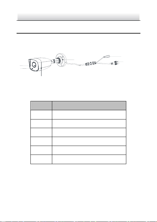
1 Appearance Description
This network bullet camera appearance is shown as the figures
below.
Network Bullet Camera Overview Figure 1-1
Description Table 1-1
Note:
For cameras support power over Ethernet (PoE), the power is passed
along with data on Ethernet cabling. And a switch supports PoE
function is required.
Page 12

Network Bullet Camera·Quick Start Guide
11
11
2 Installation
Before you start:
● Make sure the device in the package is in good condition and all
the assembly parts are included.
● The standard power supply is 12 VDC, please make sure your
power supply matches with your camera.
● Make sure all the related equipment is power-off during the
installation.
● Check the specification of the products for the installation
environment.
● Make sure that the wall is strong enough to withstand four
times the weight of the camera and the bracket.
● Make sure that there is no reflective surface too close to the
camera lens. The IR light from the camera may reflect back into
the lens causing reflection.
Ceiling/Wall Mounting 2.1
Before you start:
Both wall mounting and ceiling mounting are suitable for the bullet
camera. Ceiling mounting will be taken as an example in this section.
And you can take steps of ceiling mounting as a reference for wall
mounting.
Page 13
Network Bullet Camera·Quick Start Guide
12
12
3-Φ 4 mm
Cable Hole
Side
Opening
Screw Hole
template
Φ 55 mm
Φ 68 mm
Φ 18 mm
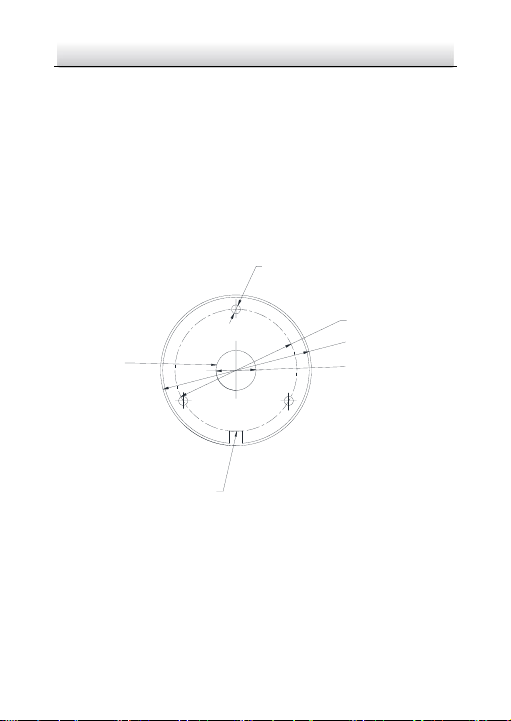
Steps:
1. Paste the drill template (supplied) to the desired mounting
position on the ceiling/wall.
2. Drill the screw holes in the ceiling/wall according to the supplied
drill template.
Note:
Drill the cable hole, if adopting ceiling outlet to route the cable.
Figure 2-1 The Drill Template
3. Route the cables through the cable hole (optional), or the side
opening.
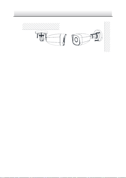
4. Fix the camera on the ceiling/wall with supplied screws.
Page 14
Network Bullet Camera·Quick Start Guide
13
13
Figure 2-2 Fix the Camera on the Ceiling/Wall
Note:
In the supplied screw package, both self-tapping screws, and
expansion bolts are contained.
If the ceiling is cement, expansion bolts are required to fix the
camera. If the ceiling is wooden, self-tapping screws are required.
5. Connect the corresponding power cord, and network cable.
6. Power on the camera, and set the network configuration (for
details, refer to 3 Set the Network Camera over the LAN and 4
Access via Web Browser) to check whether the image is gotten
from the optimum angle. If not, adjust the surveillance angle.
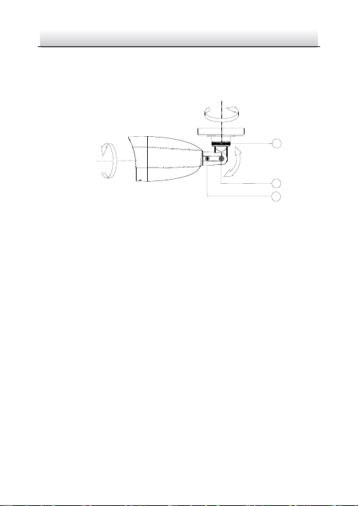
1) Loosen the No.1 adjusting screw to adjust the rotation
position [0° to 360°].
2) Tighten the No.1 adjusting screw.
3) Loosen the No.2 adjusting screw to adjust the tilting position
[-90° to 90°].
4) Tighten the No. 2 adjusting screw.
Page 15
Network Bullet Camera·Quick Start Guide
14
14
R: 0° to 360°
T: -90° to 90°
P: 0° to 360°
3
2
1
5) Loosen the No.3 fix ring to adjust the pan position [0° to
360°].
6) Tighten the No.3 fix ring.
Figure 2-3 3-aix Adjustment
7. (Optional) Install the waterproof jacket. Refer to 2.3 Installation of
Waterproof Jacket for details.
Ceiling/Wall Mounting with Junction Box 2.2
Before you start:
Both wall mounting and ceiling mounting are suitable for the
bullet camera. Wall mounting will be taken as an example in this
section. And you can take steps of wall mounting as a reference
for ceiling mounting.
You need to purchase a junction box first.
Steps:
1. Paste the drill template (supplied) to the desired mounting
position on the wall/ceiling.
Page 16
Network Bullet Camera·Quick Start Guide
15
15
Screw
Hole
Cable Hole
3 - Φ 4 mm
Φ 70 mm
Junction Box
Cover
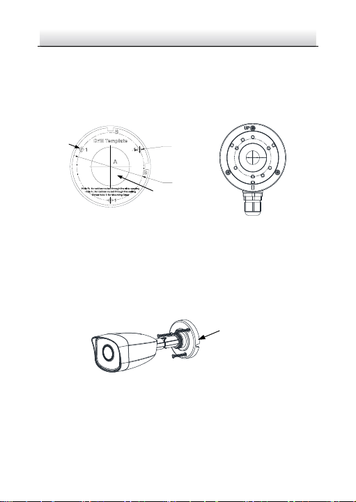
2. Drill the screw holes and the cable hole (optional) in the
wall/ceiling according to the drill template.
Note:
Drill the cable hole, if adopting ceiling outlet to route the cable.
Figure 2-4 The Drill Template
3. Take apart the junction box, and align the screw holes of the bullet
camera with those on the junction box’ cover.
4. Fix the camera on the junction box’s cover with three PM4 × 10
screws.
Figure 2-5 Fix the Camera on Junction Box’s Cover
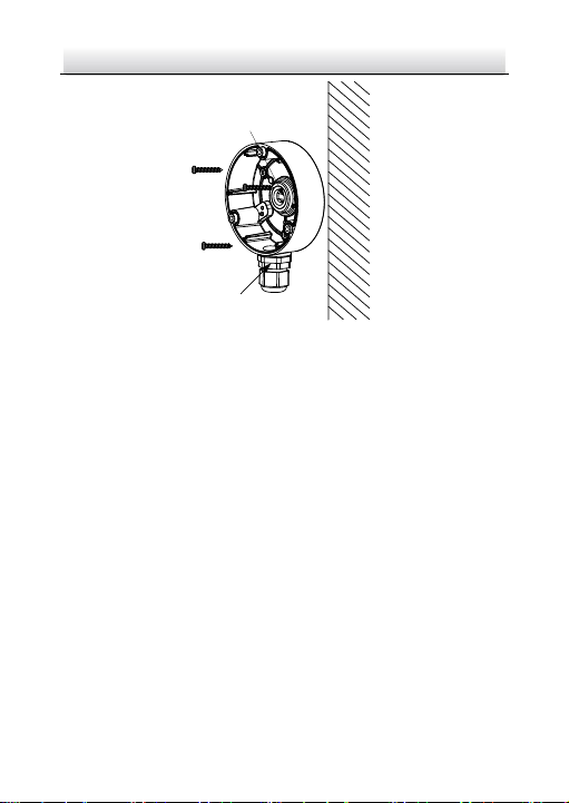
5. Secure the junction box’s body with three supplied screws on the
wall.
Page 17
Network Bullet Camera·Quick Start Guide
16
16
Cable Gland
Waterproof
Cover
Figure 2-6 Fix the Junction Box on the Wall
6. Route the cables through the cable hole. Here we take bottom
cable hole as the example to describe the installation.
1). Separate the waterproof cover and the cable gland from the
junction box.
2). Route the cable through the bottom cable hole and the
cable gland.
3). Screw the cable gland back on the bottom cable hole.
4). Screw the waterproof cover back on the side cable hole.
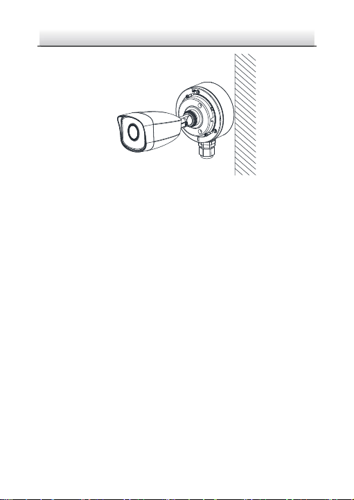
7. Combine the junction box cover with its body with three screws
on the junction box’s cover.
Page 18
Network Bullet Camera·Quick Start Guide
17
17
Figure 2-7 Combine Junction Box’s Cover with its Body
8. Repeat steps 5 to 7 of 2.1 Ceiling/Wall Mounting to complete the
installation.
Installation of Waterproof Jacket 2.3
Purpose:
It is recommended to adopt the waterproof jacket (supplied) for the
network interface when the camera is installed outdoor.
Steps:
1. If the network cable has been settled down, cut off the plug of the
network cable first.
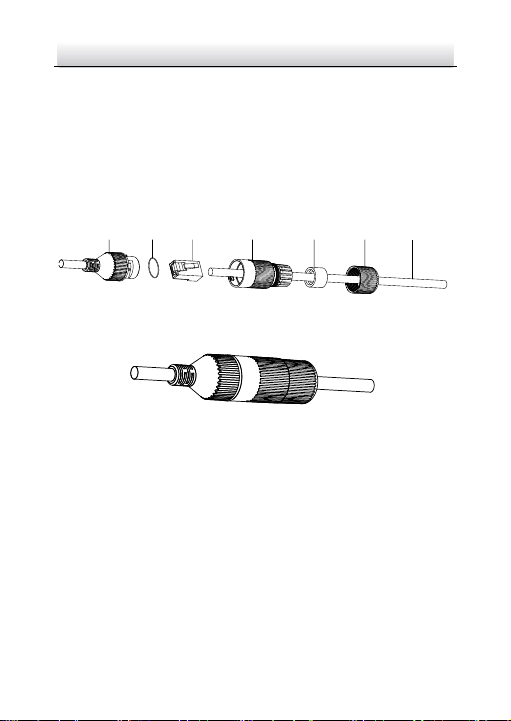
2. Route the network cable through the following components in
sequence: fix nut, waterproof ring, and the main body of the
waterproof jacket, as shown in the figure below.
3. Insert the waterproof ring into the main body of the waterproof
jacket, to increase the sealing ability of the components.
Page 19
Network Bullet Camera·Quick Start Guide
18
18
Network Interface
O-ring Plug
Waterproof Jacket Waterproof Ring Fix Nut Network Cable
4. Wire the plug and network cables up.
5. Fix the O-ring to the network interface of the camera, and then
connect the network cables.
6. Wrap the network interface with the main body of the waterproof
jacket, and then rotate the fix nut clockwise to assemble it to the
main body of the waterproof jacket.
Components of Waterproof Jacket Figure 2-8
Install Waterproof Jacket Figure 2-9
Page 20
Network Bullet Camera·Quick Start Guide
19
19
Network Cable
or
Network Camera
Computer
Network Cable
Network Cable
or
or
Network Camera Computer
3 Set the Network Camera over the
LAN
Note:
You shall acknowledge that the use of the product with Internet
access might be under network security risks. For avoidance of any
network attacks and information leakage, please strengthen your
own protection.
If the product does not work properly, contact your dealer or the
nearest service center for help.
Wiring 3.1
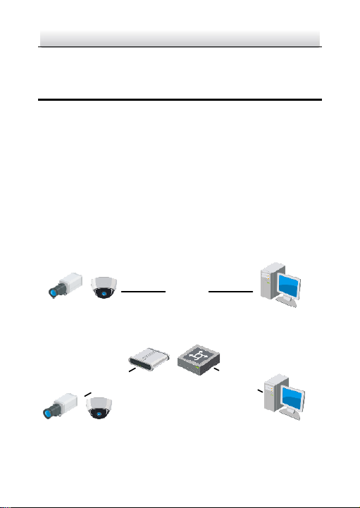
Connect the camera to network according to the following figures.
Connect Directly Figure 3-1
Connect via a Switch or a Router Figure 3-2
Page 21

Network Bullet Camera·Quick Start Guide
20
20
Activate the Camera 3.2
You are required to activate the camera first by setting a strong
password for it before you can use the camera.
Activation via web browser, activation via SADP, and activation via
client software are all supported. We will take activation via SADP
software and activation via web browser as examples to introduce
the camera activation.
Note:
Refer to the User Manual of Network Camera for activation via client
software.
Activation via Web Browser 3.2.1
Steps:
1. Power on the camera. Connect the camera to your computer or
the switch/router which your computer connects to.
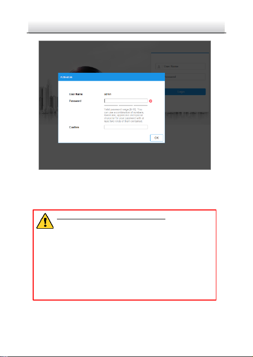
2. Input the IP address into the address bar of the web browser, and
press Enter to enter the activation interface.
Notes:
The default IP address of the camera is 192.168.1.64.
The computer and the camera should belong to the same
subnet.
For the camera enables the DHCP by default, you need to use
the SADP software to search the IP address.
Page 22
Network Bullet Camera·Quick Start Guide
21
21
Activation Interface (Web) Figure 3-3
3. Create a password and input the password into the password
field.
STRONG PASSWORD RECOMMENDED– W e highly
recommend you create a strong password of your own
choosing (using a minimum of 8 characters, including
upper case letters, lower case letters, numbers, and
special characters) in order to increase the security of
your product. And we recommend you reset your
password regularly, especially in the high security
system, resetting the password monthly or weekly can
better protect your product.
4. Confirm the password.
Page 23
Network Bullet Camera·Quick Start Guide
22
22
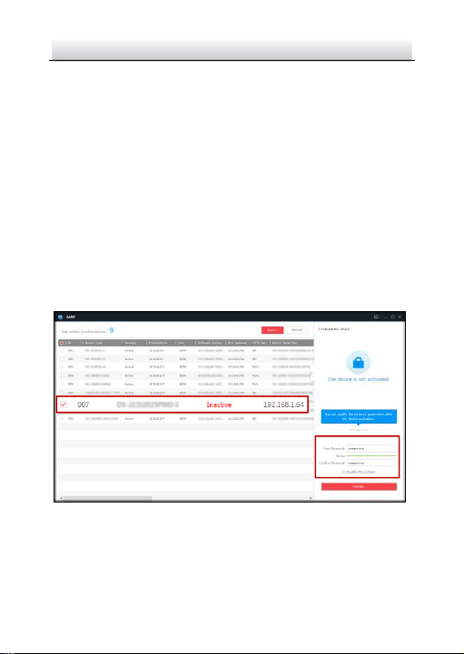
Select inactive device.
Input and confirm
password.
5. Click OK to save the password and enter the live view interface.
Activation via SADP Software 3.2.2
SADP software is used for detecting the online device, activating the
camera, and resetting the password.
Get the SADP software from the supplied disk or the official website,
and install the SADP according to the prompts.
Follow the steps to activate the camera.
Steps:
1. Run the SADP software to search the online devices.
2. Check the device status from the device list, and select the
inactive device.
SADP Interface Figure 3-4
Note:
The SADP software supports activating the camera in batch. Refer
to the user manual of SADP software for details.
Page 24

Network Bullet Camera·Quick Start Guide
23
23
3. Create and input the new password in the password field, and
confirm the password.
STRONG PASSWORD RECOMMENDED– W e highly
recommend you create a strong password of your own
choosing (using a minimum of 8 characters, including
upper case letters, lower case letters, numbers, and
special characters) in order to increase the security of
your product. And we recommend you reset your
password regularly, especially in the high security
system, resetting the password monthly or weekly can
better protect your product.
Note:
You can enable the Hik-Connect service for the device during
activation. Refer to Chapter 5.1 for detailed information.
4. Click Activate to start activation.
You can check whether the activation is completed on the popup
window. If activation failed, make sure that the password meets
the requirement and try again.
Modify the IP Address 3.3
Purpose:
To view and configure the camera via LAN (Local Area Network), you
need to connect the network camera in the same subnet with your
PC.
Use the SADP software or client software to search and change the
IP address of the device. We take modifying the IP Address via SADP
software as an example to introduce the IP address modification.
Page 25
Network Bullet Camera·Quick Start Guide
24
24
For IP address modification via client software, refer to the user
manual of client software.
Steps:
1. Run the SADP software.
2. Select an active device.
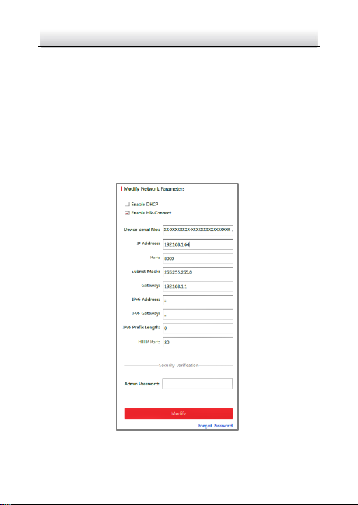
3. Change the device IP address to the same subnet with your
computer by either modifying the IP address manually or checking
the checkbox of Enable DHCP.
Modify the IP Address Figure 3-5
Page 26

Network Bullet Camera·Quick Start Guide
25
25
Note:
You can enable the Hik-Connect service for the device during
activation. Refer to Chapter 5.1 for detailed information.
4. Input the admin password and click Modify to activate your IP
address modification.
The batch IP address modification is supported by the SADP. Refer to
the user manual of SADP for details.
Page 27

Network Bullet Camera·Quick Start Guide
26
26
4 Access via Web Browser
System Requirement:
Operating System: Microsoft Windows XP SP1 and above version
CPU: 2.0 GHz or higher
RAM: 1G or higher
Display: 1024×768 resolution or higher
Web Browser: Internet Explorer 8.0 and above version, Apple Safari
5.0.2 and above version, Mozilla Firefox 5.0 and above version and
Google Chrome 18 and above version
Steps:
1. Open the web browser.
2. In the browser address bar, input the IP address of the network
camera, and press the Enter key to enter the login interface.
Note:
The default IP address is 192.168.1.64. You are recommended
to change the IP address to the same subnet with your
computer.
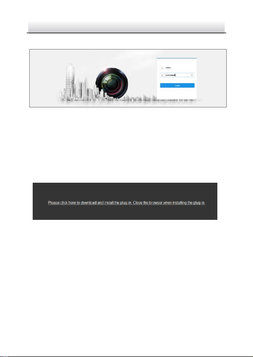
3. Input the user name and password.
The admin user should configure the device accounts and
user/operator permissions properly. Delete the unnecessary
accounts and user/operator permissions.
Note:
The device IP address gets locked if the admin user performs 7
failed password attempts (5 attempts for the user/operator).
Page 28
Network Bullet Camera·Quick Start Guide
27
27
4. Click Login.
Login Interface Figure 4-1
5. Install the plug-in before viewing the live video and managing the
camera. Follow the installation prompts to install the plug-in.
Note:
You may have to close the web browser to finish the installation of
the plug-in.
Download Plug-in Figure 4-2
6. Reopen the web browser after the installation of the plug-in and
repeat steps 2 to 4 to login.
Note:
For detailed instructions of further configuration, please refer to
the user manual of network camera.
Page 29

Network Bullet Camera·Quick Start Guide
28
28
5 Operate via Hik-Connect App
Purpose:
Hik-Connect is an application for mobile devices. With the App, you
can view live image of the camera, receive alarm notification and so
on.
Note:
Hik-Connect service is not supported by certain camera models.
Enable Hik-Connect Service on Camera 5.1
Purpose:
Hik-Connect service should be enabled on your camera before using
the service.
You can enable the service through SADP software or web browser.
Enable Hik-Connect Service via SADP Software 5.1.1
Steps:
1. Check the checkbox of Enable Hik-Connect on:
1). "Activate the Device" page during camera activation, refer to
Chapter 3.2.2.
2). Or "Modify Network Parameters" page during modifying IP
address, refer to Chapter 3.3.
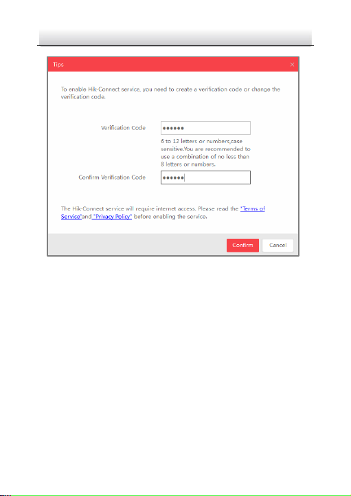
2. Create a verification code or change the verification code.
Page 30
Network Bullet Camera·Quick Start Guide
29
29
Verification Code Setting (SADP) Figure 5-1
Note:
The verification code is required when you add the camera to
Hik-Connect app.
3. Click and read "Terms of Service" and "Privacy Policy".
4. Confirm the settings.
Enable Hik-Connect Service via Web Browser 5.1.2
Before you start:
You need to activate the camera before enabling the service. Refer to
Chapter 3.2.
Page 31
Network Bullet Camera·Quick Start Guide
30
30
Steps:
1. Access the camera via web browser. Refer to Chapter 4.
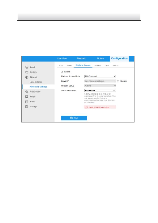
2. Enter platform access configuration interface: Configuration >
Network > Advanced Settings > Platform Access.
Platform Access Configuration (Web) Figure 5-2
3. Select Platform Access Mode as Hik-Connect.
4. Check the checkbox of Enable.
5. Click and read "Terms of Service" and "Privacy Policy" in pop-up
window.
6. Create a verification code or change the verification code for the
camera.
Note:
The verification code is required when you add the camera to
Hik-Connect app.
Page 32
Network Bullet Camera·Quick Start Guide
31
31
7. Save the settings.
Hik-Connect Setup 5.2
Steps:
1. Download and install the Hik-Connect app by searching
“Hik-Connect” in App Store or Google PlayTM.
2. Launch the app and register for a Hik-Connect user account.
3. Log in Hik-Connect app after registration.
Add Camera to Hik-Connect 5.3
Before you start:
You need to enable the Hik-Connect service on camera before
adding it to your Hik-Connect account. Refer to Chapter 5.1.
Steps:
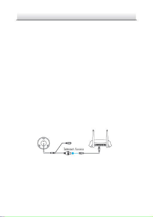
1. Use a network cable to connect the camera with a router if the
camera does not support Wi-Fi.
Figure 5-3 Connect a Router
Note:
After the camera connects to the network, please wait one minute
before any operation on the camera using Hik-Connect app.
Page 33
Network Bullet Camera·Quick Start Guide
32
32
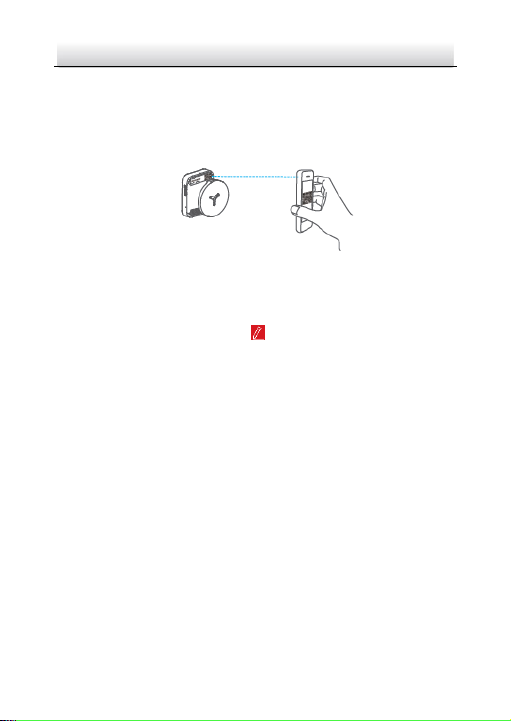
2. In the Hik-Connect app, tap “+” on the upper-right corner and
then scan the QR code of the camera to add the camera.
You can find the QR code on the camera or on the cover of the
Quick Start Guide of the camera in the package.
Figure 5-4 Scan QR Code
Note:
If the QR code is missing or too blur to be recognized, you can also
add the camera by tapping the icon and inputting the
camera's serial number.
3. Input the verification code of your camera.
Note:
● The required verification code is the code you create or
change when you enabling Hik-Connect service on camera.
● If you forget the verification code, you can check the current
verification code on Platform Access configuration page via
web browser.
4. Follow the prompts to set the network connection and add the
camera to your Hik-Connect account.
Note:
For detailed information, refer to the user manual of the
Hik-Connect app.
Page 34

Network Bullet Camera·Quick Start Guide
33
33
Initialize the Memory Card 5.4
Steps:
Check the memory card status by tapping on the Storage Status in
the Device Settings interface.
If the memory card status displays as Uninitialized, tap to initialize
it. The status will then change to Normal. You can then start
recording any event triggered video in the camera such as motion
detection.
Page 35

0
UD06935B-A
 Loading...