

Page 1

Video Access Control Terminal
User Manual
Page 2

Video Access Control Terminal User Manual
i
User Manual
©2019 Hangzhou Hikvision Digital Technology Co., Ltd.
It includes instructions on how to use the Product. The software embodied in the Product is governed by the user
license agreement covering that Product.
About this Manual
This Manual is subject to domestic and international copyright protection. Hangzhou Hikvision Digital Technology Co.,
Ltd. (“Hikvision”) reserves all rights to this manual. This manual cannot be reproduced, changed, translated, or
distributed, partially or wholly, by any means, without the prior written permission of Hikvision.
Trademarks
and other Hikvision marks are the property of Hikvision and are registered trademarks or the subject of
applications for the same by Hikvision and/or its affiliates. Other trademarks mentioned in this manual are the
properties of their respective owners. No right of license is given to use such trademarks without express permission.
Disclaimer
TO THE MAXIMUM EXTENT PERMITTED BY APPLICABLE LAW, HIKVISION MAKES NO WARRANTIES, EXPRESS OR
IMPLIED, INCLUDING WITHOUT LIMITATION THE IMPLIED WARRANTIES OF MERCHANTABILITY AND FITNESS FOR A
PARTICULAR PURPOSE, REGARDING THIS MANUAL. HIKVISION DOES NOT WARRANT, GUARANTEE, OR MAKE ANY
REPRESENTATIONS REGARDING THE USE OF THE MANUAL, OR THE CORRECTNESS, ACCURACY, OR RELIABILITY OF
INFORMATION CONTAINED HEREIN. YOUR USE OF THIS MANUAL AND ANY RELIANCE ON THIS MANUAL SHALL BE
WHOLLY AT YOUR OWN RISK AND RESPONSIBILITY.
REGARDING TO THE PRODUCT WITH INTERNET ACCESS, THE USE OF PRODUCT SHALL BE WHOLLY AT YOUR OWN
RISKS. OUR COMPANY SHALL NOT TAKE ANY RESPONSIBILITIES FOR ABNORMAL OPERATION, PRIVACY LEAKAGE OR
OTHER DAMAGES RESULTING FROM CYBER ATTACK, HACKER ATTACK, VIRUS INSPECTION, OR OTHER INTERNET
SECURITY RISKS; HOWEVER, OUR COMPANY WILL PROVIDE TIMELY TECHNICAL SUPPORT IF REQUIRED.
SURVEILLANCE LAWS VARY BY JURISDICTION. PLEASE CHECK ALL RELEVANT LAWS IN YOUR JURISDICTION BEFORE
USING THIS PRODUCT IN ORDER TO ENSURE THAT YOUR USE CONFORMS THE APPLICABLE LAW. OUR COMPANY SHALL
NOT BE LIABLE IN THE EVENT THAT THIS PRODUCT IS USED WITH ILLEGITIMATE PURPOSES.
IN THE EVENT OF ANY CONFLICTS BETWEEN THIS MANUAL AND THE APPLICABLE LAW, THE LATER PREVAILS.
Support
Should you have any questions, please do not hesitate to contact your local dealer.
Data Protection
During the use of device, personal data will be collected, stored and processed. To protect data, the development of
Hikvision devices incorporates privacy by design principles. For example, for device with facial recognition features,
biometrics data is stored in your device with encryption method; for fingerprint device, only fingerprint template will
be saved, which is impossible to reconstruct a fingerprint image.
As data controller, you are advised to collect, store, process and transfer data in accordance with the applicable data
protection laws and regulations, including without limitation, conducting security controls to safeguard personal data,
such as, implementing reasonable administrative and physical security controls, conduct periodic reviews and
assessments of the effectiveness of your security controls.
Page 3

Video Access Control Terminal User Manual
ii
Regulatory Information
FCC Information
Please take attention that changes or modification not expressly approved by the party responsible for compliance
could void the user’s authority to operate the equipment.
FCC compliance: This equipment has been tested and found to comply with the limits for a Class B digital device,
pursuant to part 15 of the FCC Rules. These limits are designed to provide reasonable protection against harmful
interference in a residential installation. This equipment generates, uses and can radiate radio frequency energy and, if
not installed and used in accordance with the instructions, may cause harmful interference to radio communications.
However, there is no guarantee that interference will not occur in a particular installation. If this equipment does cause
harmful interference to radio or television reception, which can be determined by turning the equipment off and on,
the user is encouraged to try to correct the interference by one or more of the following measures:
—Reorient or relocate the receiving antenna.
—Increase the separation between the equipment and receiver.
—Connect the equipment into an outlet on a circuit different from that to which the receiver is connected.
—Consult the dealer or an experienced radio/TV technician for help.
This equipment should be installed and operated with a minimum distance 20cm between the radiator and your body.
FCC Conditions
This device complies with part 15 of the FCC Rules. Operation is subject to the following two conditions:
1. This device may not cause harmful interference.
2. This device must accept any interference received, including interference that may cause undesired operation.
EU Conformity Statement
This product and - if applicable - the supplied accessories too are marked with "CE" and comply therefore
with the applicable harmonized European standards listed under the RE Directive 2014/53/EU, the EMC
Directive 2014/30/EU, the RoHS Directive 2011/65/EU.
2012/19/EU (WEEE directive): Products marked with this symbol cannot be disposed of as unsorted
municipal waste in the European Union. For proper recycling, return this product to your local supplier
upon the purchase of equivalent new equipment, or dispose of it at designated collection points. For more
information see: www.recyclethis.info
2006/66/EC (battery directive): This product contains a battery that cannot be disposed of as unsorted
municipal waste in the European Union. See the product documentation for specific battery information.
The battery is marked with this symbol, which may include lettering to indicate cadmium (Cd), lead (Pb), or
mercury (Hg). For proper recycling, return the battery to your supplier or to a designated collection point.
For more information see: www.recyclethis.info
Industry Canada ICES-003 Compliance
This device meets the CAN ICES-3 (B)/NMB-3(B) standards requirements.
This device complies with Industry Canada licence-exempt RSS standard(s). Operation is subject to the following two
conditions:
(1) this device may not cause interference, and
(2) this device must accept any interference, including interference that may cause undesired operation of the device.
Le présent appareil est conforme aux CNR d'Industrie Canada applicables aux appareils radioexempts de licence.
L'exploitation est autorisée aux deux conditions suivantes :
(1) l'appareil ne doit pas produire de brouillage, et
(2) l'utilisateur de l'appareil doit accepter tout brouillage radioélectrique subi, même si le brouillage est susceptible
d'en compromettre le fonctionnement.
Page 4
Video Access Control Terminal User Manual
iii
Under Industry Canada regulations, this radio transmitter may only operate using an antenna of a type and maximum
(or lesser) gain approved for the transmitter by Industry Canada. To reduce potential radio interference to other users,
the antenna type and its gain should be so chosen that the equivalent isotropically radiated power (e.i.r.p.) is not more
than that necessary for successful communication.
Conformément à la réglementation d'Industrie Canada, le présent émetteur radio peut
fonctionner avec une antenne d'un type et d'un gain maximal (ou inférieur) approuvé pour l'émetteur par Industrie
Canada. Dans le but de réduire les risques de brouillage radioélectrique à l'intention des autres utilisateurs, il faut
choisir le type d'antenne et son gain de sorte que la puissance isotrope rayonnée équivalente (p.i.r.e.) ne dépasse pas
l'intensité nécessaire à l'établissement d'une communication satisfaisante.
This equipment should be installed and operated with a minimum distance 20cm between the radiator and your body.
Cet équipement doit être installé et utilisé à une distance minimale de 20 cm entre le radiateur et votre corps.
Safety Instruction
These instructions are intended to ensure that user can use the product correctly to avoid danger or property loss.
The precaution measure is divided into Warnings and Cautions:
Warnings: Neglecting any of the warnings may cause serious injury or death.
Cautions: Neglecting any of the cautions may cause injury or equipment damage.
Warnings
All the electronic operation should be strictly compliance with the electrical safety regulations, fire prevention
regulations and other related regulations in your local region.
Please use the power adapter, which is provided by normal company. The power consumption cannot be less than
the required value.
Do not connect several devices to one power adapter as adapter overload may cause over-heat or fire hazard.
Please make sure that the power has been disconnected before you wire, install or dismantle the device.
When the product is installed on wall or ceiling, the device shall be firmly fixed.
If smoke, odors or noise rise from the device, turn off the power at once and unplug the power cable, and then
please contact the service center.
If the product does not work properly, please contact your dealer or the nearest service center. Never attempt to
disassemble the device yourself. (We shall not assume any responsibility for problems caused by unauthorized repair
or maintenance.)
Cautions
Do not drop the device or subject it to physical shock, and do not expose it to high electromagnetism radiation.
Avoid the equipment installation on vibrations surface or places subject to shock (ignorance can cause equipment
damage).
Do not place the device in extremely hot (refer to the specification of the device for the detailed operating
temperature), cold, dusty or damp locations, and do not expose it to high electromagnetic radiation. The
appropriate operation temperature is 0℃ to +45℃, and the storage temperature should be -10℃ to +55℃.
The device cover for indoor use shall be kept from rain and moisture.
Warnings Follow
these safeguards
to prevent
serious injury or
death.
Cautions Follow these
precautions to
prevent potential
injury or material
damage.
Page 5

Video Access Control Terminal User Manual
iv
Exposing the equipment to direct sun light, low ventilation or heat source such as heater or radiator is forbidden
(ignorance can cause fire danger).
Do not aim the device at the sun or extra bright places. A blooming or smear may occur otherwise (which is not a
malfunction however), and affecting the endurance of sensor at the same time.
Please use the provided glove when open up the device cover, avoid direct contact with the device cover, because
the acidic sweat of the fingers may erode the surface coating of the device cover.
Please use a soft and dry cloth when clean inside and outside surfaces of the device cover, do not use alkaline
detergents.
Please keep all wrappers after unpack them for future use. In case of any failure occurred, you need to return the
device to the factory with the original wrapper. Transportation without the original wrapper may result in damage on
the device and lead to additional costs.
Improper use or replacement of the battery may result in hazard of explosion. Replace with the same or equivalent
type only. Dispose of used batteries according to the instructions provided by the battery manufacturer.
Please take care of your card and report card loss in time when card is lost.
If you require a higher security level, use multiple authentication modes.
Multiple card types are supported. Please select an appropriate card type according to the card performance and
the usage scenarios.
Page 6

Video Access Control Terminal User Manual
1
Table of Contents
1 Overview ................................................................................................................................................................. 3
1.1 Introduction ....................................................................................................................................................... 3
1.2 Main Features .................................................................................................................................................... 3
2 Appearance.............................................................................................................................................................. 4
2.1 Appearanceof DS-K1T500S Model ...................................................................................................................... 4
2.2 Video Access Control Terminal Connector ........................................................................................................... 5
3 Installation ............................................................................................................................................................... 6
4 Terminal Connection ................................................................................................................................................ 7
5 Wiring Description ................................................................................................................................................... 9
5.1 External Device Wiring Overview ........................................................................................................................ 9
5.2 The Wiring of External Card Reader ...................................................................................................................10
5.2.1 The Wiring of External RS-485 Card Reader .................................................................................................10
5.3 Card Reader Connection ....................................................................................................................................10
5.3.1 The Wiring of Wiegand................................................................................................................................11
5.3.2 The Wiring of RS-485 Output .......................................................................................................................11
6 Activating the Access Control Terminal ...................................................................................................................12
6.1 Activating via SADP Software .............................................................................................................................12
6.2 Activating via Client Software ............................................................................................................................13
7 iVMS-4200 Access Control Client Operation ............................................................................................................16
7.1 Overview of iVMS-4200 Client Software ............................................................................................................16
7.1.1 Description .................................................................................................................................................16
7.1.2 Running Environment..................................................................................................................................16
7.1.3 Client Performance .....................................................................................................................................16
7.2 Resource Management .....................................................................................................................................17
7.2.1 Access Control Device Management ............................................................................................................17
7.2.2 Network Settings ........................................................................................................................................38
7.2.3 Capture Settings..........................................................................................................................................40
7.2.4 RS-485 Settings ...........................................................................................................................................41
7.2.5 Door Group Management ...........................................................................................................................42
7.3 Permission Configuration ..................................................................................................................................45
7.3.1 Person Management ...................................................................................................................................45
7.3.2 Card Management ......................................................................................................................................51
7.3.3 Schedule Template ......................................................................................................................................57
7.3.4 Door Status Management ...........................................................................................................................62
7.3.5 Linkage Configuration .................................................................................................................................66
7.3.6 Permission Configuration ............................................................................................................................70
7.3.7 Advanced Functions ....................................................................................................................................74
7.4 Event and Alarm Management ..........................................................................................................................87
7.4.1 Real-Time Access Control Event and Alarm ..................................................................................................87
7.4.2 Event Management .....................................................................................................................................88
7.5 System Maintenance .........................................................................................................................................90
7.5.1 Log Management ........................................................................................................................................90
7.5.2 Account Management .................................................................................................................................91
7.5.3 Auto Backup Settings ..................................................................................................................................92
7.5.4 System Configuration ..................................................................................................................................92
8 iVMS-4200 Control Client Operation .......................................................................................................................97
8.1 Importing Access Control Device .......................................................................................................................97
8.2 Live View and Playcak Settings ...........................................................................................................................97
8.3 Group Management ..........................................................................................................................................99
8.3.1 Adding the Group........................................................................................................................................99
8.3.2 Importing Encoding Device to Group ......................................................................................................... 100
8.3.3 Editing the Group/Camera......................................................................................................................... 101
8.3.4 Removing Cameras from the Group ........................................................................................................... 101
Page 7

Video Access Control Terminal User Manual
2
8.3.5 Deleting the Group ................................................................................................................................... 102
8.4 Live View......................................................................................................................................................... 102
8.4.1 Starting and Stopping the Live View .......................................................................................................... 105
8.4.2 Manual Recording and Capture ................................................................................................................. 107
8.4.3 Instant Playback ........................................................................................................................................ 109
8.4.4 Custom Window Division .......................................................................................................................... 111
8.4.5 Other Functions in Live View ..................................................................................................................... 112
8.5 Playback.......................................................................................................................................................... 113
8.5.1 Storing on Storage Device ......................................................................................................................... 113
8.5.2 Normal Playback ....................................................................................................................................... 115
8.5.3 Event Playback .......................................................................................................................................... 122
9 Appendix .............................................................................................................................................................. 125
9.1 DIP Switch Introduction ................................................................................................................................... 125
9.2 Indicator and Buzzer Description ..................................................................................................................... 126
9.3 Access Controller Model List............................................................................................................................ 127
Page 8

Video Access Control Terminal User Manual
3
1 Overview
1.1 Introduction
DS-K1T500S is a series video access control terminal with multiple advanced technologies including face detection, WiFi, smart card recognition, and HD camera (2 MP optional). It supports offline operation.
1.2 Main Features
Transmission modes of wired network (TCP/TP), Wi-Fi, RS-485, and Wiegand
Face detection and picture capturing function implemented by built-in camera (2 MP optional)
Supports RS-485 communication for connecting external card reader
Supports working as a card reader, and supports Wiegand interface and RS-485 interface for accessing the
controller
Supports EHome
Max. 50,000 cards Max. and 200,000 access control events records
Supports multiple authentication modes including card, card + password, and so on.
Supports Mifare card/ QR Code reading
Tampering detection, unlocking overtime alarm, invalid card swiping over times alarm, duress card alarm,
and so on
Supports security door control unit connection
Protection level: IP65
Data can be permanently saved after power-off
Page 9

Video Access Control Terminal User Manual
4
2 Appearance
2.1 Appearanceof DS-K1T500S Model
Please refer to the following content for detailed information of DS-K1T500S series model
Table 2-1 Description of DS-K1T500S Series Model
No.
Description
1
Mic
2
Camera
3
LED Indicator
4
Card Swiping Area
5
Doorbell Button
6
Voice Talk Button
7
Loud Speaker
In the Event Card Interact interface in the iVMS-4200 Client Software, choose the alarm output of Event Bell. You
can connect a bell at the alarm output terminal. For details about configuring the Event Bell alarm output, see
the User Manual of iVMS- 4200 Client Software.
Page 10
Video Access Control Terminal User Manual
5
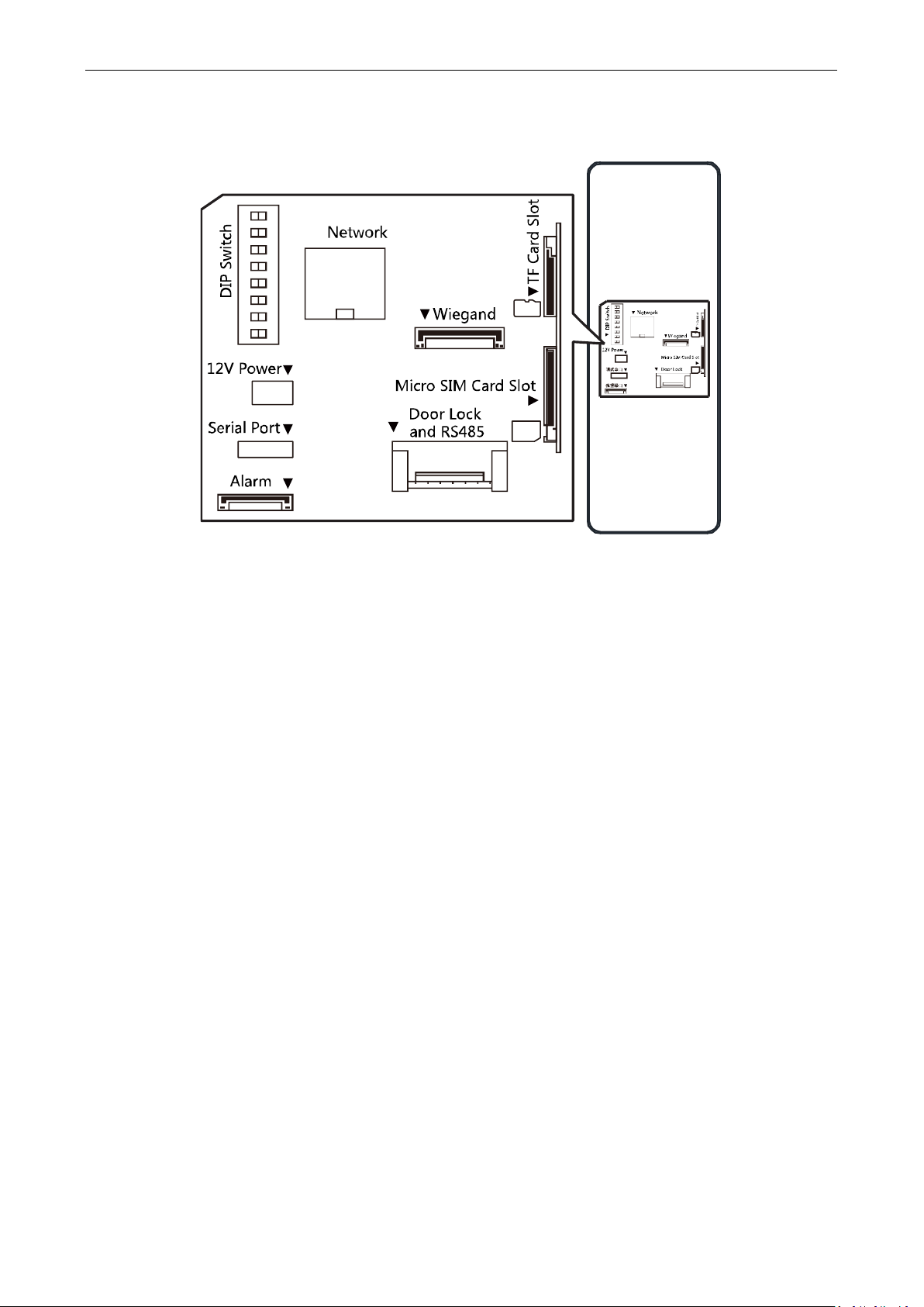
2.2 Video Access Control Terminal Connector
Page 11
Video Access Control Terminal User Manual
6
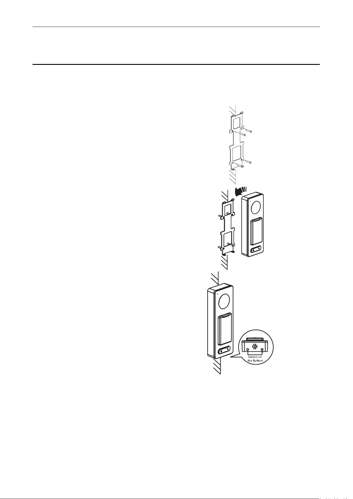
3 Installation
Before You Start:
Make sure that the device in the package is in good condition and all the assembly parts are included.
Make sure that the wall is strong enough to withstand three times the weight of the terminal.
Set the DIP address before installation.
Steps:
1. Connect the cables with the connecter on the
rear panel of the device. Route the cables
through the cable hole of the mounting plate.
The cable holes are on the right side, left side
and lower side of the rear cover. If the
right/left side cable hole is selected, remove
the plastic sheet of the cable hole.
2. Secure the mounting plate on the wall with 4
supplied screws.
3. Connect the corresponding cables.
4. Push the terminal in the mounting plate from
bottom up.
5. Tighten the screws on the bottom of the
terminal to fix the terminal on the mounting
plate and complete the installation.
Page 12
Video Access Control Terminal User Manual
7
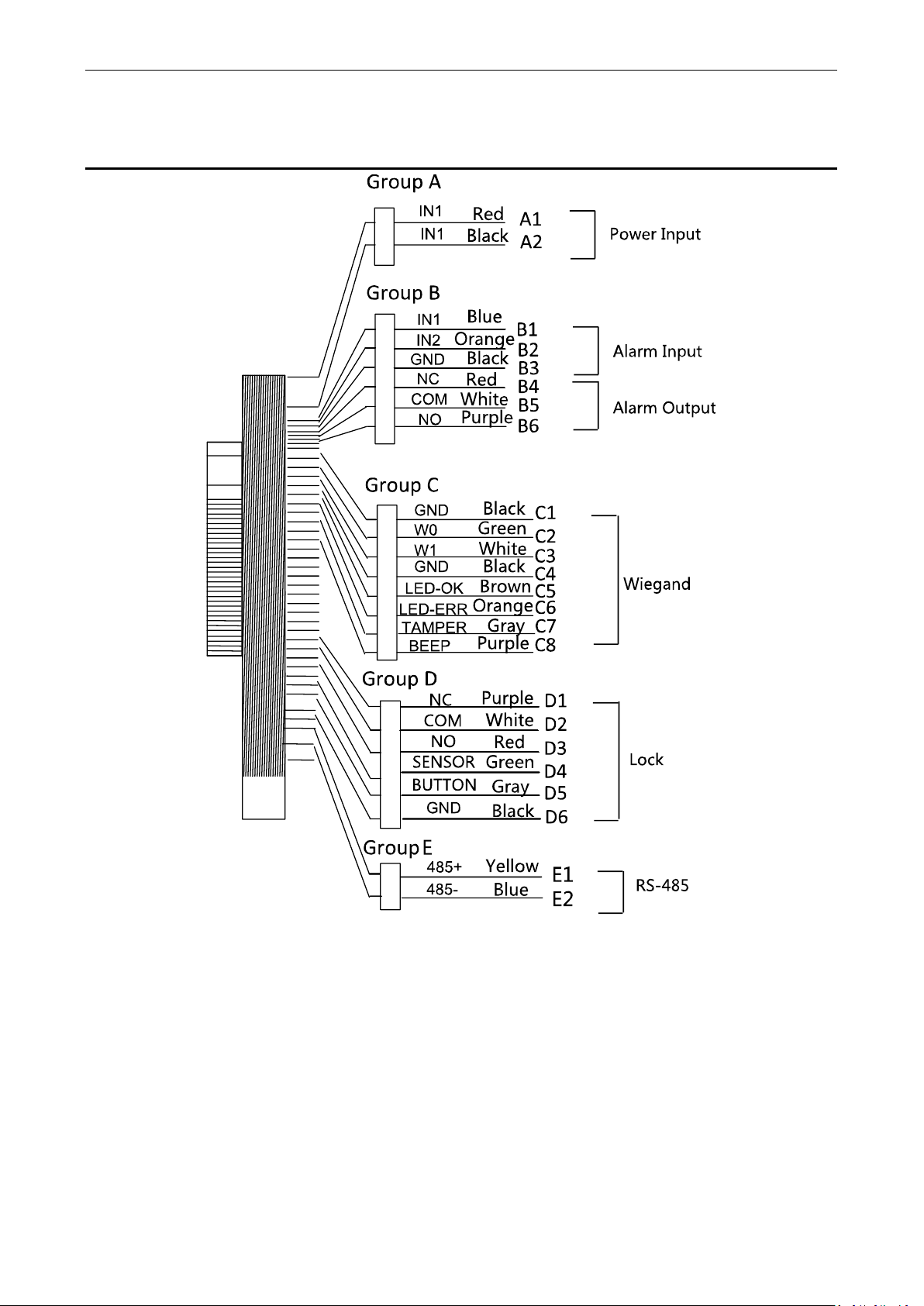
4 Terminal Connection
Page 13

Video Access Control Terminal User Manual
8
Table 4-1 Terminal Description
Group
No.
Function
Color
Terminal
Name
Description
Group A
A1
Power Input
Red
+12V
12V DC Power Supply
A2
Black
GND
GND
Group B
B1
Alarm Input
Yellow
IN1
Alarm Input 1
B2
Orange
IN2
Alarm Input 2
B3
Black
GND
GND
B4
Alarm Output
Red
NC
Alarm Output Wiring
B5
White
COM
B6
Purple
NO
Group C
C1
Wiegand
Black
GND
GND
C2
Green
W0
Wiegand Wiring 0
C3
White
W1
Wiegand Wiring 1
C4
Black
GND
GND
C5
Brown
LED-OK
Wiegand
Authenticated
C6
Orange
LED-ERR
Wiegand
Authentication Failed
C7
Gray
TAMPER
Tampering Alarm
Wiring
C7
Purple
BEEP
Buzzer Wiring
Group D
D1
Lock
Purple
NC
Lock Wiring
D2
White
COM
D3
Red
NO
D4
Green
SENSOR
Door Magnetic Signal
Input
D5
Gray
BUTTON
Exit Door Wiring
D6
Black
GND
GND
Group E
E1
RS-485
Yellow
485 +
RS-485 Wiring
E2
Blue
485 -
Page 14

Video Access Control Terminal User Manual
9
5 Wiring Description
5.1 External Device Wiring Overview
Notes:
If set the working mode as the controller mode, the terminal can connect the RS-485 card reader or security control
unit via RS-485 protocol. For details about wiring of RS-485 card reader, see 5.2.1 The Wiring of External RS-485
Card Reader.
If set the working mode as the controller mode, the terminal cannot connect the Wiegand card reader.
The security control unit can also connect the external devices. For details, see the specified user manual of security
control unit.
Page 15
Video Access Control Terminal User Manual
10
5.2 The Wiring of External Card Reader
5.2.1 The Wiring of External RS-485 Card Reader
If set the working mode as the controller mode, the DIP switch No.6 should be set as OFF.
If set the working mode as card reader mode, the DIP switch No. from 1 to 4 should be set as OFF.
Set the external card reader’s RS-485 DIP switch to 2. For details about DIP switch configuration, see 9.1 DIP
Switch Introduction.
5.3 Card Reader Connection
The access control terminal can be switched into the card reader mode. It can access to the access control as a
card reader, and supports Wiegand communication port and RS-485 communication port.
When the access control terminal works as a card reader, it only supports being connected to the controller, but
does not support alarm input or output, or the connection of external devices.
Page 16
Video Access Control Terminal User Manual
11
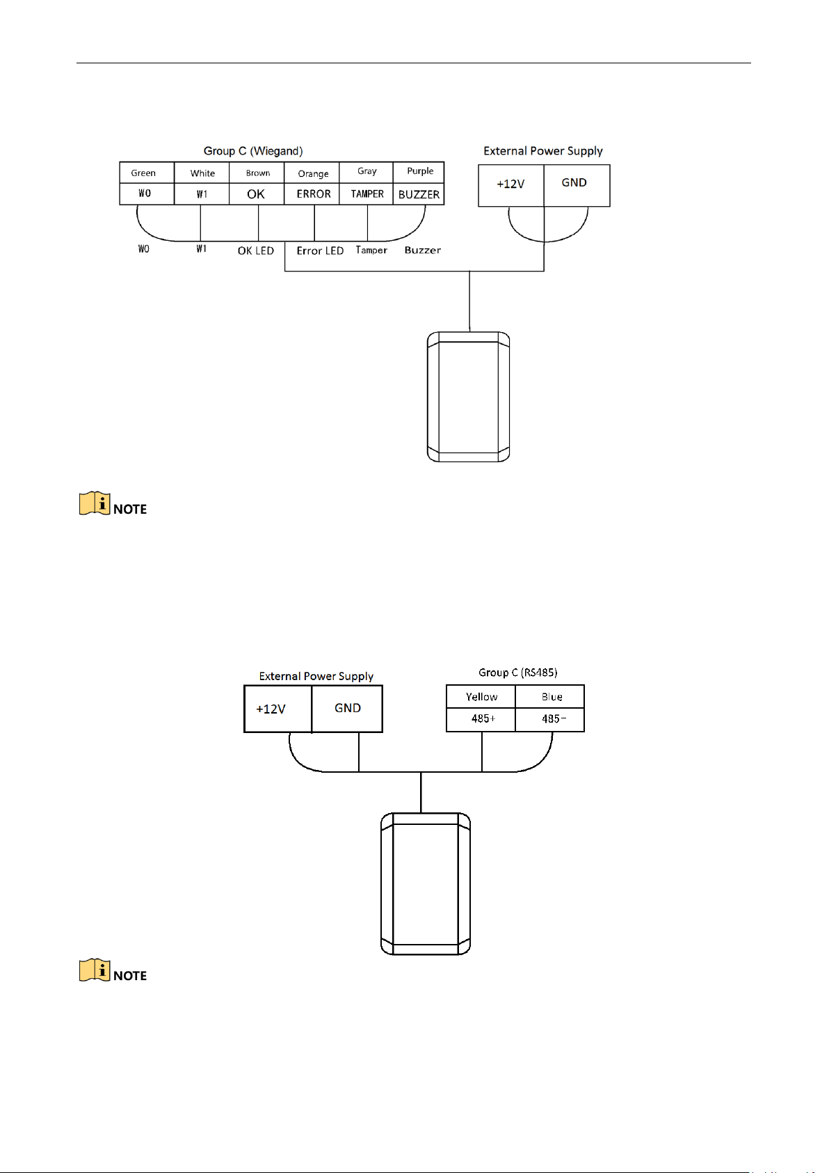
5.3.1 The Wiring of Wiegand
When the access control terminal works as a card reader, you must the WG_ERR, BUZZER and WG_OK
interfaces if you want to control the LED and buzzer of the Wiegand card reader.
Set the working mode of the terminal as card reader, if the terminal is required to work as a card reader. The
card reader mode support to communicate by Wiegand or RS-485.
The distance of Wiegand communication should be no longer than 80 m.
The external power supply and the access control terminal should use the same GND cable.
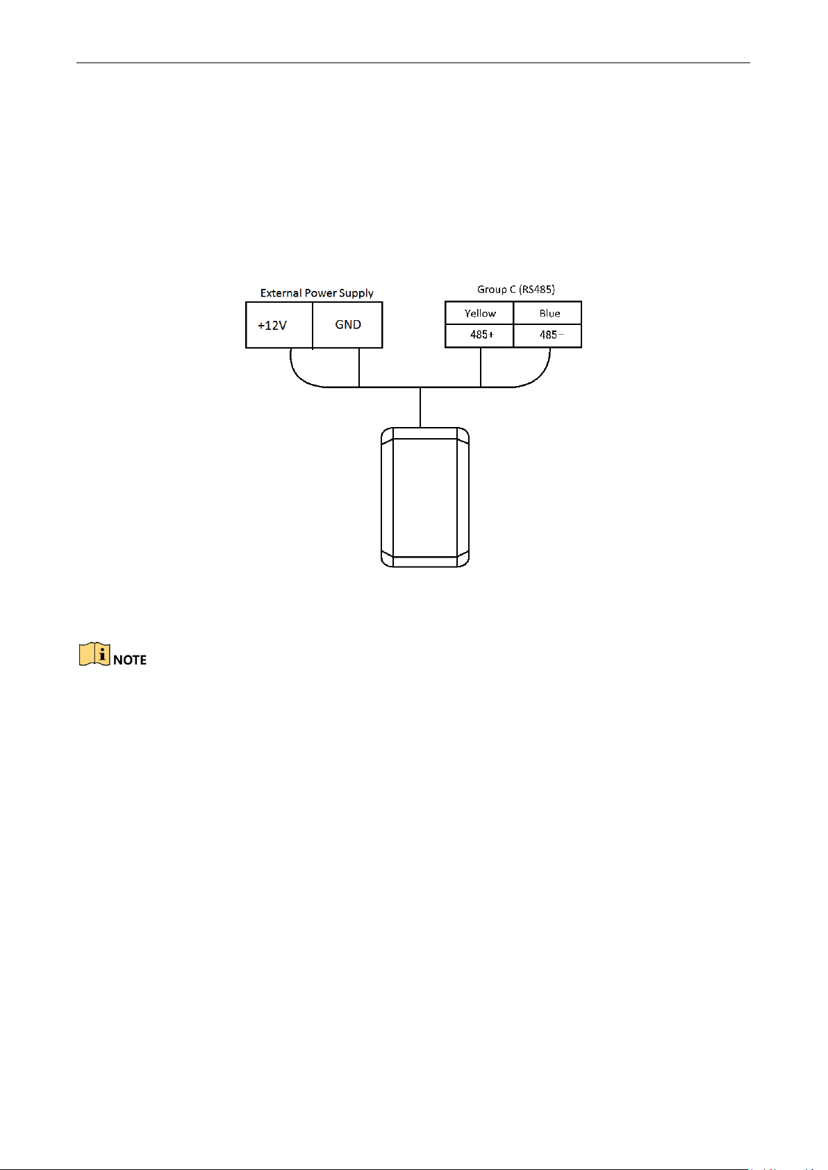
5.3.2 The Wiring of RS-485 Output
Set the working mode of the terminal as card reader, if the terminal requires working as a card reader.
When the access control terminal works as a RS-485 card reader, you can set the RS-485 address via the DIP
switch.
The external power supply and the access control terminal should use the same GND cable.
Page 17
Video Access Control Terminal User Manual
12
6 Activating the Access Control Terminal
Purpose:
You are required to activate the terminal first before using it.
Activation via SADP, and Activation via client software are supported.
The default values of the control terminal are as follows.
The default IP address: 192.0.0.64.
The default port No.: 8000.
The default user name: admin.
6.1 Activating via SADP Software
SADP software is used for detecting the online device, activating the device, and resetting the password.
Get the SADP software from the supplied disk or the official website, and install the SADP according to the
prompts. Follow the steps to activate the control panel.
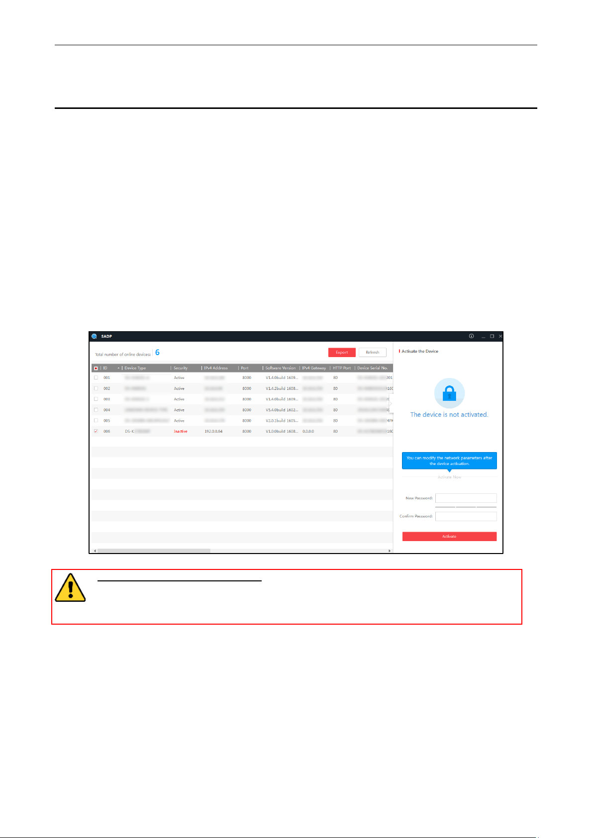
Steps:
1. Run the SADP software to search the online devices.
2. Check the device status from the device list, and select an inactive device.
3. Create a password in the password field, and confirm the password.
STRONG PASSWORD RECOMMENDED– We highly recommend you create a strong password of
your own choosing (using a minimum of 8 characters, including upper case letters, lower case
letters, numbers, and special characters) in order to increase the security of your product. And we
recommend you reset your password regularly, especially in the high security system, resetting the
password monthly or weekly can better protect your product.
4. Click Activate to activate the device.
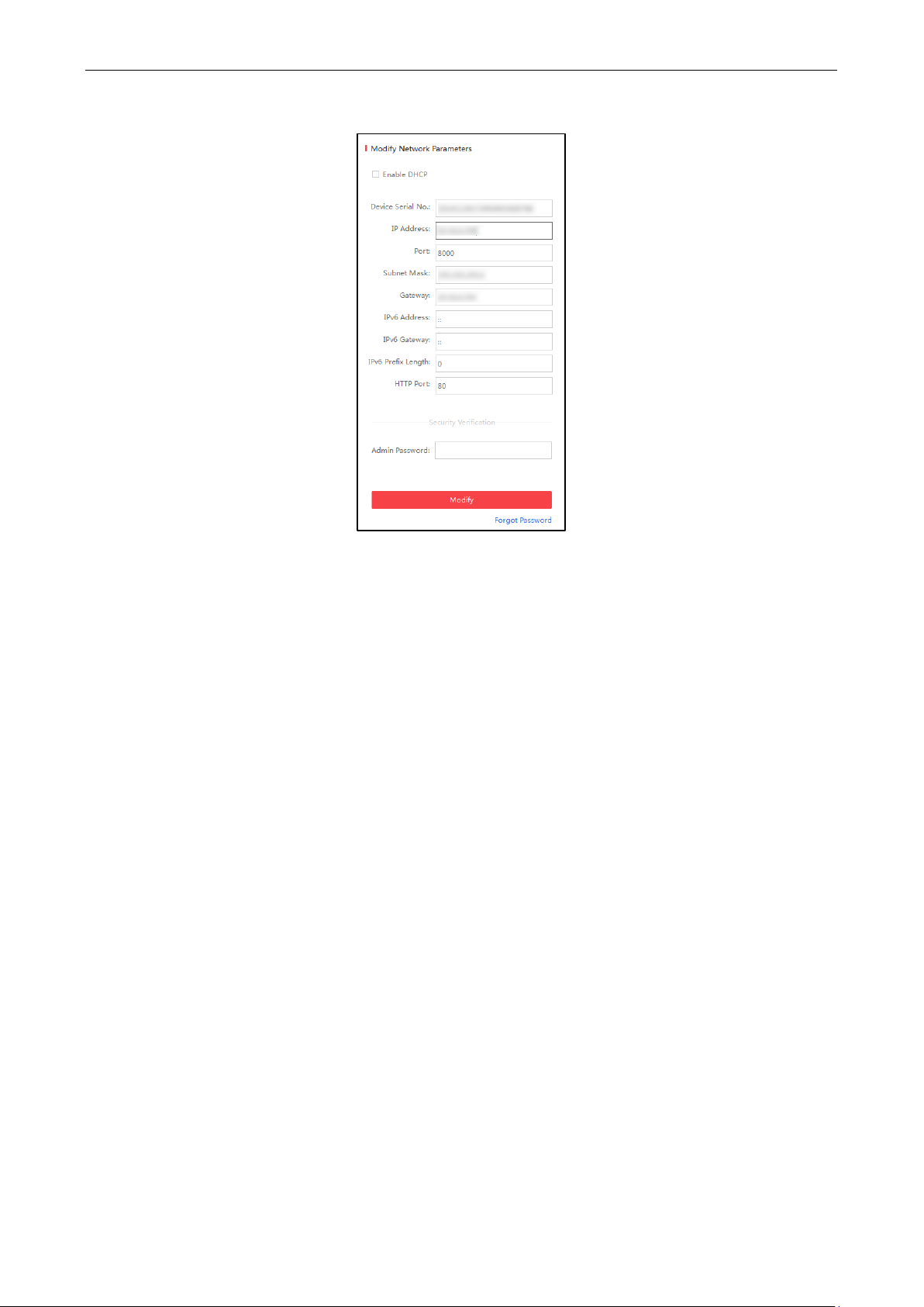
5. Check the activated device, you can change the device IP address to the same network segment with your
computer by either modifying the IP address manually or checking the checkbox of Enable DHCP.
Page 18
Video Access Control Terminal User Manual
13
6. Input the password and click the Modify button to activate your IP address modification.
6.2 Activating via Client Software
The client software is versatile video management software for multiple kinds of devices.
Get the client software from the supplied disk or the official website, and install the software according to the
prompts. Follow the steps to activate the control panel.
Steps:
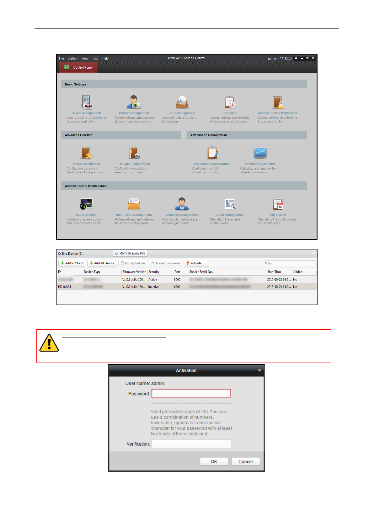
1. Run the client software and the control panel of the software pops up, as shown in the figure below.
Page 19
Video Access Control Terminal User Manual
14
2. Click the Device Management to enter the Device Management interface.
3. Check the device status from the online device list, and select an inactive device.
4. Click the Activate button to pop up the Activation interface.
5. In the pop-up window, create a password in the password field, and confirm the password.
STRONG PASSWORD RECOMMENDED– We highly recommend you create a strong password of
your own choosing (using a minimum of 8 characters, including upper case letters, lower case
letters, numbers, and special characters) in order to increase the security of your product. And we
recommend you reset your password regularly, especially in the high security system, resetting the
password monthly or weekly can better protect your product.
Page 20
Video Access Control Terminal User Manual
15
6. Click OK button to activate.
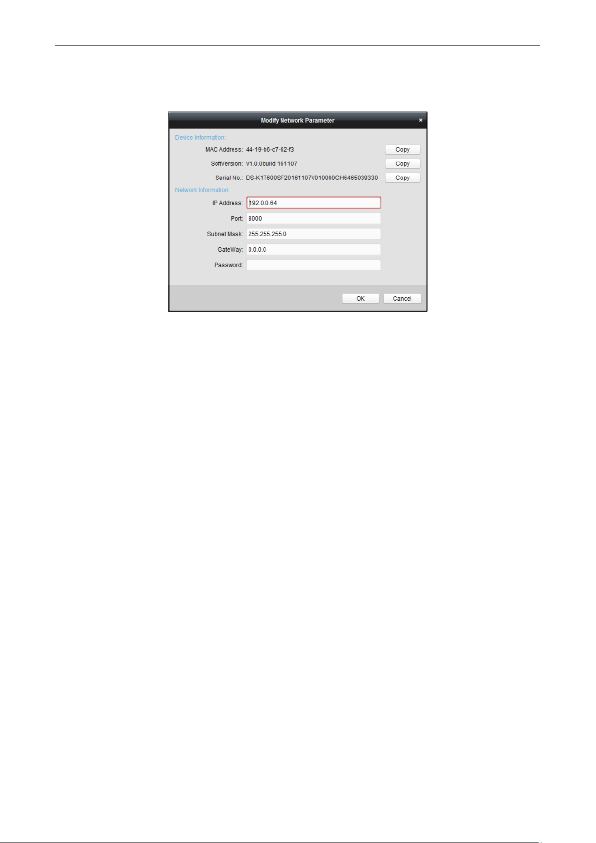
7. Click the Modify Netinfor button to pop up the Network Parameter Modification interface.
8. Change the device IP address to the same network segment with your computer by either modifying the IP
address manually.
9. Input the password and click the OK button to save the settings.
Page 21

Video Access Control Terminal User Manual
16
7 iVMS-4200 Access Control Client Operation
7.1 Overview of iVMS-4200 Client Software
7.1.1 Description
The iVMS-4200 Access Control Client is a client-based access control system for management of access control
devices. With intuitive and easy-to-use operations, it provides multiple functionalities, including access control
device management, person/card management, permission configuration, door status management, attendance
management, event search, etc.
This user manual describes the function, configuration and operation steps of iVMS-4200 Access Control Client.
To ensure the properness of usage and stability of the client, please refer to the contents below and read the
manual carefully before installation and operation.
7.1.2 Running Environment
Operating System: Microsoft Windows 7/Windows 2008 R2/Windows 8.1/Windows 10 (32-bit or 64-bit), Windows
XP SP3 (32-bit)
CPU: Intel Pentium IV 3.0 GHz or above
Memory: 2G or above
Video Card: RADEON X700 Series or above
GPU: 256 MB or above
For high stability and good performance, these above system requirements must be met.
The software does not support 64-bit operating system; the above mentioned 64-bit operating system refers
to the system which supports 32-bit applications as well.
7.1.3 Client Performance
The client performance is shown as follows:
Client Performance
Quantity
User Account
Up to 16 user accounts (including super user) supported
Access Control Device
Up to 16 access control devices supported
Access Control Point
Up to 64 access control points (doors) supported
Person
Up to 2,000 persons supported
Card
Up to 2,000 cards supported
Department
Up to 10 levels of departments supported
Page 22

Video Access Control Terminal User Manual
17
7.2 Resource Management
After running the iVMS-4200 Access Control Client, the access control device should be added to the client for
the remote configuration and management.
7.2.1 Access Control Device Management
Click icon on the control panel to enter the access control device management interface.
The interface is divided into two parts: Device Management area and Online Device Detection area.
Device Management
Manage the access control devices, including adding, editing, deleting, and batch time synchronizing
functions.
Online Device Detection
Automatically detect online devices in the same subnet with the client, and the detected devices can be
added to the client in an easy way.
Note: The client can manage up to 16 access control devices and 64 access control points.
Page 23
Video Access Control Terminal User Manual
18
Activating Device and Creating Password
Purpose:
If the access control device is not activated, you are required to create the password to activate them before they
can be added to the software and work properly.
Steps:
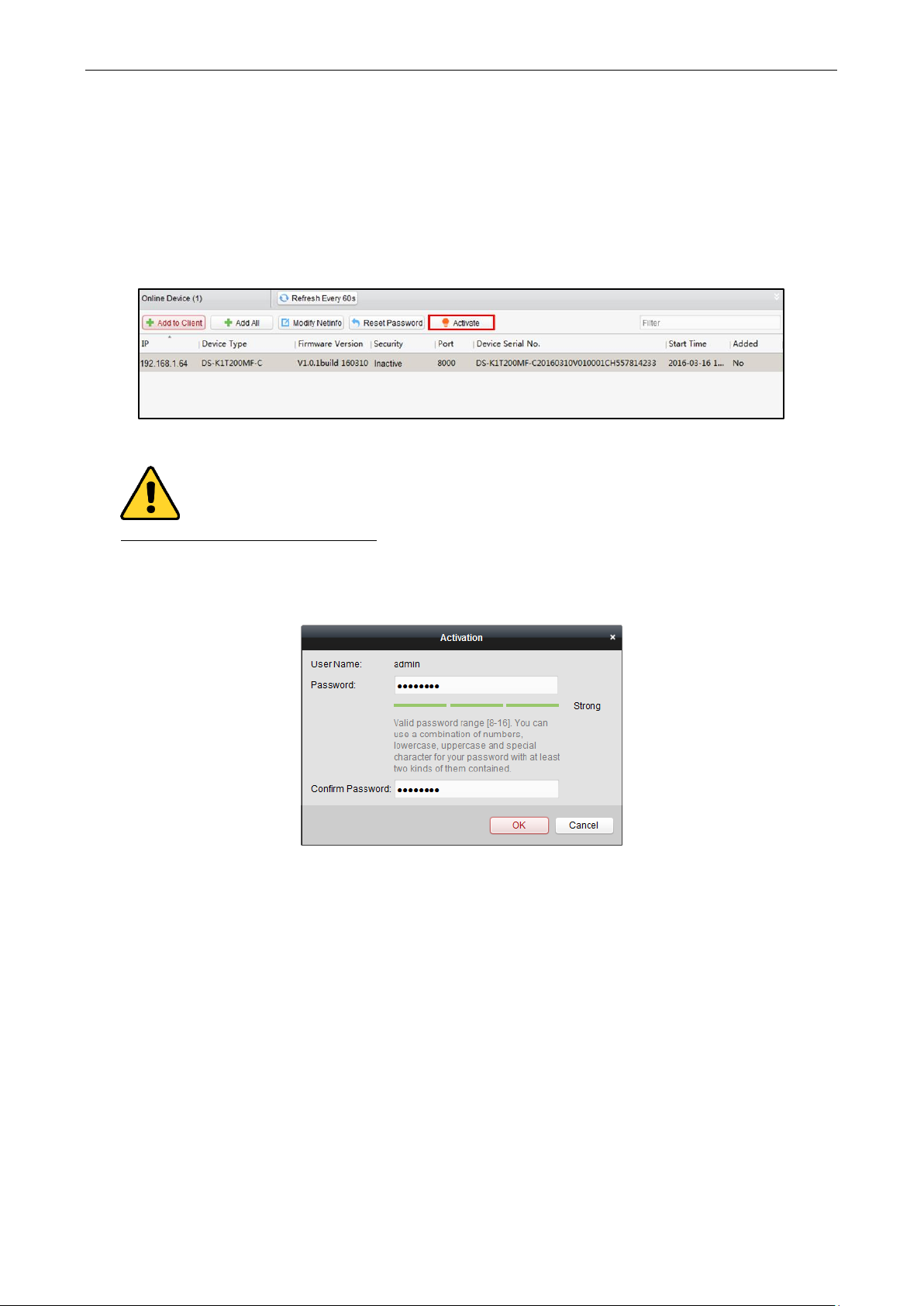
1. On the Device for Management or Online Device area, check the device status (shown on Security column)
and select an inactive device.
2. Click the Activate button to pop up the Activation interface.
3. Create a password in the password field, and confirm the password.
STRONG PASSWORD RECOMMENDED– We highly recommend you create a strong password of your own
choosing (using a minimum of 8 characters, including upper case letters, lower case letters, numbers, and
special characters) in order to increase the security of your product. And we recommend you reset your
password regularly, especially in the high security system, resetting the password monthly or weekly can
better protect your product.
4. Click OK to create the password for the device. A “The device is activated.” window pops up when the
password is set successfully.
5. Perform the following steps to edit the device’s network parameters.
1) Click Modify Netinfo to pop up the Modify Network Parameter interface.
Note: This function is only available on the Online Device area. You can change the device IP address to
the same subnet with your computer if you need to add the device to the software.
2) Input the password set in step 3 and click OK to complete the network settings.
Page 24

Video Access Control Terminal User Manual
19
3) Click OK to save the settings.
Adding Online Devices
Purpose:
The active online access control devices in the same local subnet with the client will be displayed on the Online
Device area. You can click the Refresh Every 60s button to refresh the information of the online devices.
Note: You can click to hide the Online Device area.
Steps:
1. Select the devices to be added from the list.
Note: For the inactive device, you need to create the password for it before you can add the device properly.
For detailed steps, please refer to 3.1.1 Activating Device and Creating Password.
2. Click Add to Client to open the device adding dialog box.
3. Input the required information.
Nickname: Edit a name for the device as you want.
Connection Type: Select TCP/IP as the connection type.
IP Address: Input the device’s IP address. The IP address of the device is obtained automatically in this
adding mode.
Page 25
Video Access Control Terminal User Manual
20
Port: Input the device port No.. The default value is 8000.
User Name: Input the device user name. By default, the user name is admin.
Password: Input the device password.
4. Click Add to add the device to the client.
5. (Optional) If you want to add multiple online devices to the client software, click and hold Ctrl key to select
multiple devices, and click Add to Client to open the device adding dialog box. In the pop-up message box,
enter the user name and password for the devices to be added.
If you want to add all the online devices to the client software, click Add All and click OK in the pop-up
message box. Then enter the user name and password for the devices to be added.
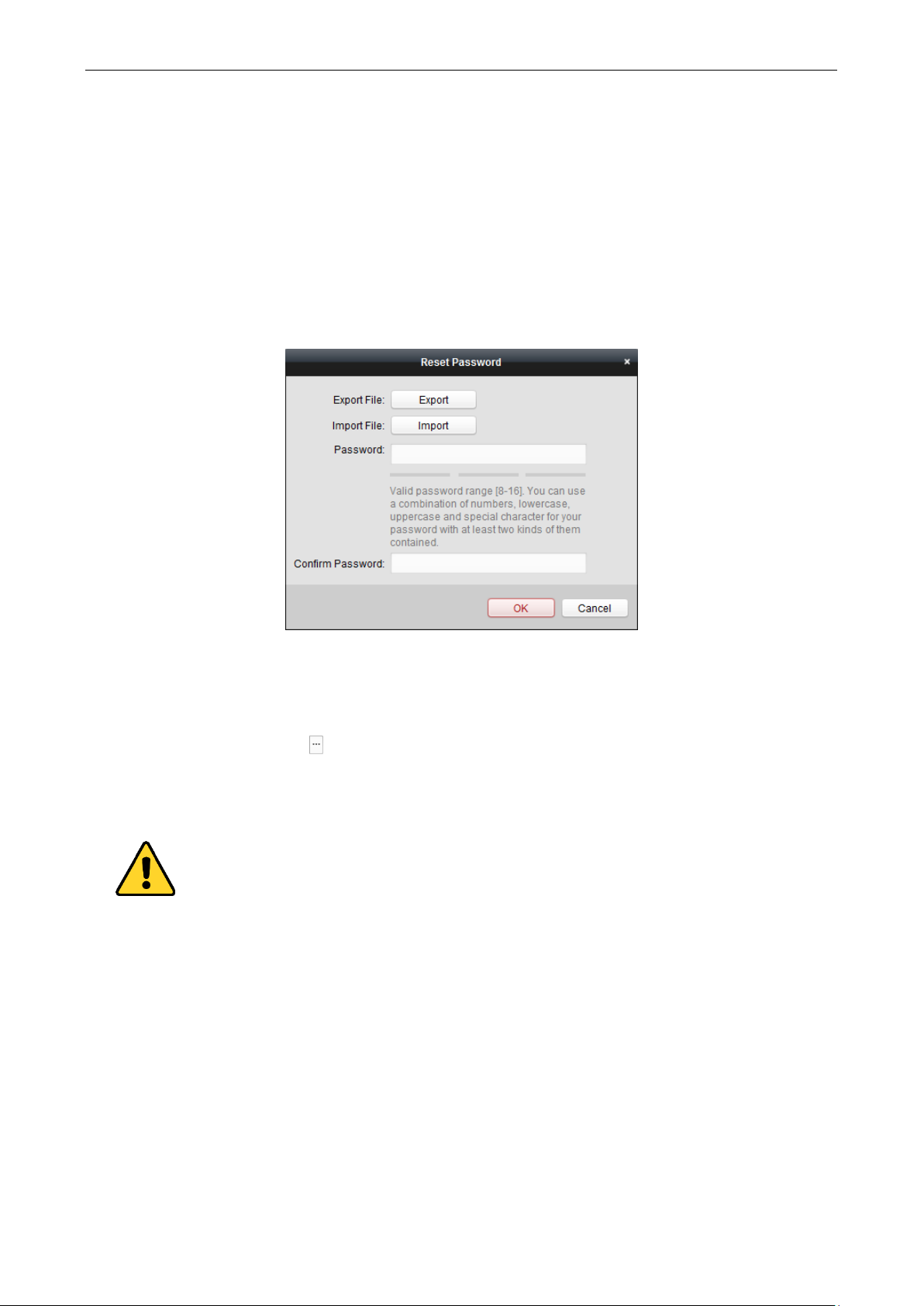
6. You can select the device from the list and click Reset Password to reset the device password.
Perform the following steps to reset the device password.
1) Click Export to save the device file on your PC.
2) Send the file to our technical engineers.
3) Our technical engineer will send you a file or an eight-digit number to you.
If you receive a file from the technical engineer, select Import File from Key Importing Mode drop-
down list and click to import the file.
If you receive an eight-digit number from the technical engineer, select Input Key from Key
Importing Mode drop-down list and input the number.
4) Input new password in text fields of Password and Confirm Password.
5) Click OK to reset the password.
The password strength of the device can be checked by the software. For your privacy, we strongly
recommend changing the password to something of your own choosing (using a minimum of 8 characters,
including upper case letters, lower case letters, numbers, and special characters) in order to increase the
security of your product. And we recommend you reset your password regularly, especially in the high
security system, resetting the password monthly or weekly can better protect your product.
Adding Access Control Device Manually
Steps:
1. Click Add Device on the Device for Management panel to enter the Add Device interface.
Page 26

Video Access Control Terminal User Manual
21
2. Input the device name.
3. Select the connection type in the dropdown list: TCP/IP, COM port (1 to 5), or EHome protocol.
TCP/IP: Connect the device via the network.
COM1 to COM5: Connect the device via the COM port.
EHome: Connect the device via EHome Protocol.
Note: For connection type of EHome protocol, please set the network center parameter first. For details,
refer to 3.2.2 Network Center Settings.
4. Set the parameters of connecting the device.
If you select the connection type as TCP/IP, you should input the device IP Address, Port No., User Name,
and Password.
If you select the connection type as COM port, you should input the Baud Rate and Dial-up value.
If you select the connection type as EHome, you should input the Account.
5. Click Add button to finish adding.
Editing Access Control Device
Purpose:
After adding the device, you can configure the added access control device’s parameters, its access control point
(door)’s parameters, and its card readers’ parameters.
Click to select the added access control device from the list, and then click Modify button to enter the Edit
Access Controller interface.
Notes:
After editing the device, you can click Apply Parameters to apply the configured parameters to the device to
take effect.
You can also click Read Parameters to get the device parameters from the device itself.
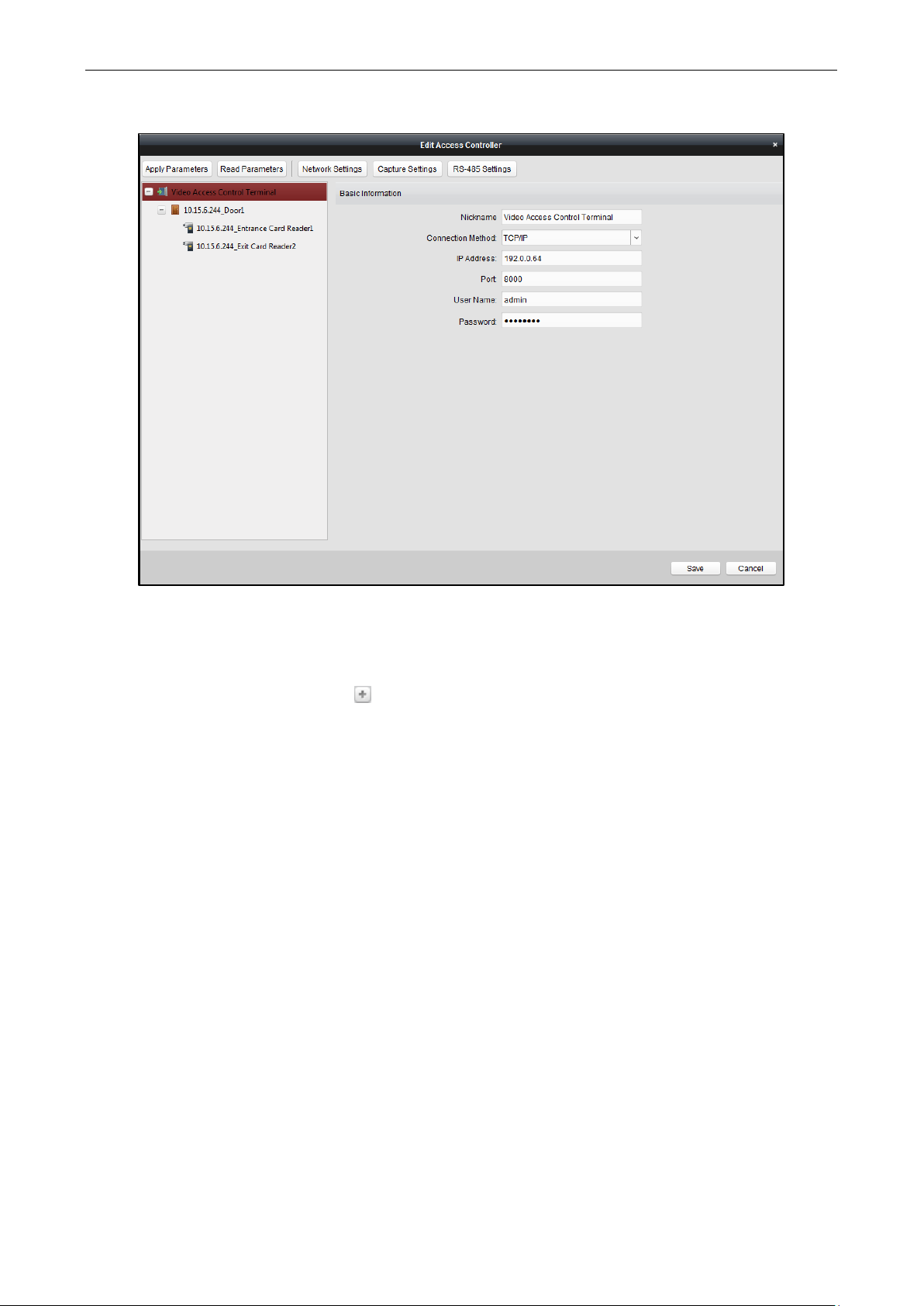
Editing Basic Information
You can configure the device basic information including IP address, port No., etc.
Steps:
1. In the device list on the left, select the access control device and you can edit its basic parameters on your
demand, which are the same as the ones when adding the device.
Page 27
Video Access Control Terminal User Manual
22
2. Click Save button to save the settings.
3. You can click Apply Parameters button to apply the updated parameters to the local memory of the device.
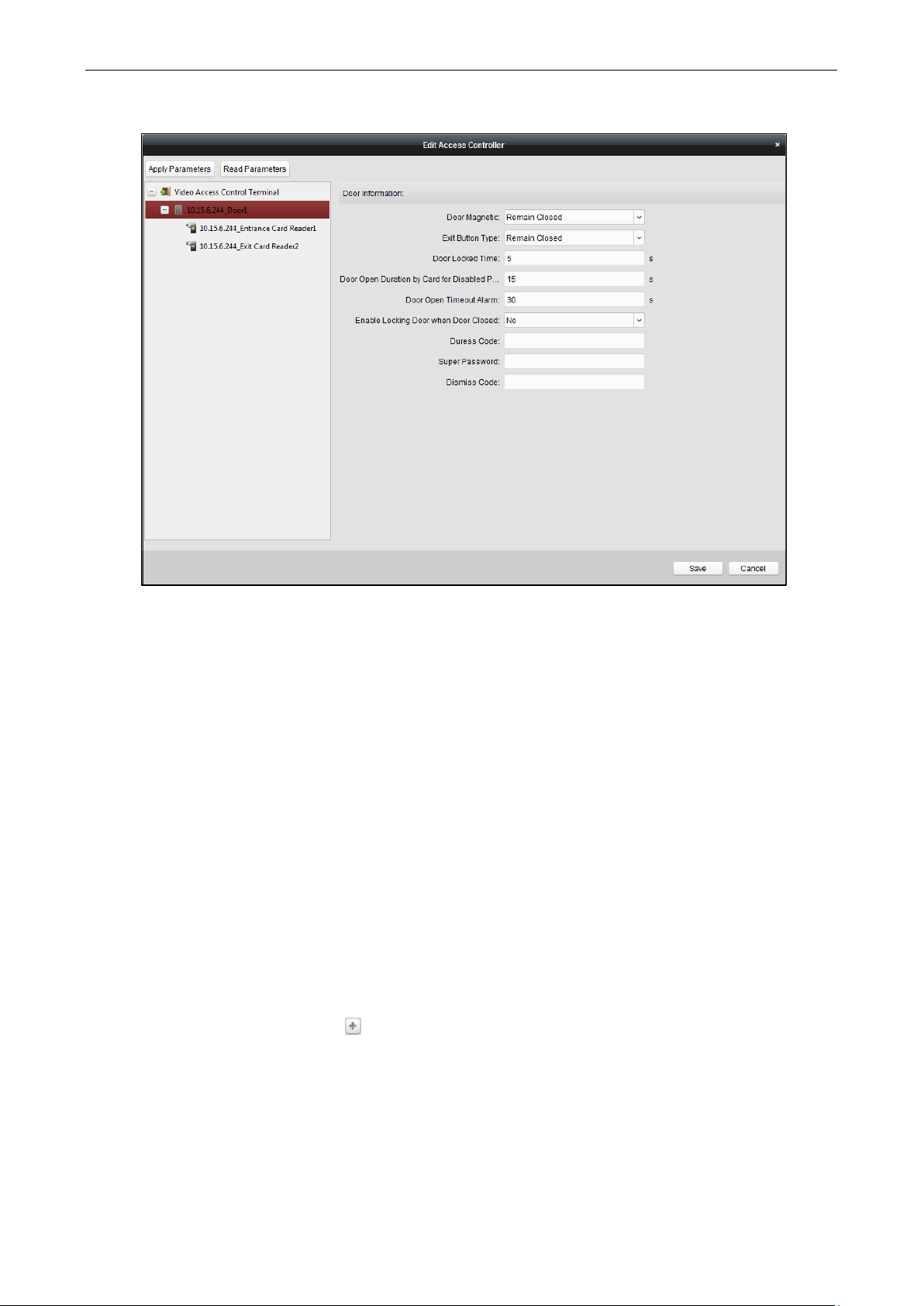
Editing Door Information
Steps:
1. In the device list on the left, click to expand the access control device, select the door (access control
point) and you can edit the information of the selected door on the right.
Page 28
Video Access Control Terminal User Manual
23
2. You can editing the following parameters:
Door Magnetic: The Door Magnetic is in the status of Normal Closed (excluding special conditions).
Exit Button Type: The Exit Button Type is in the status of Remain Open (excluding special conditions).
Door Locked Time: After swiping the normal card and relay action, the timer for locking the door starts
working.
Door Open Duration by Card for Door Extended Opening: The door magnetic can be enabled with
appropriate delay after card holder swipes the card.
Door Open Timeout Alarm: The alarm can be triggered if the door has not been close
Enable Locking Door when Door Closed: The door can be locked once it is closed even if the Door Locked
Time is not reached.
Duress Code: The door can open by inputting the duress code when there is duress. At the same time, the
client can report the duress event.
Super Password: The specific person can open the door by inputting the super password.
Dismiss Code: Input the dismiss code to stop the buzzer of the card reader.
Note: The Duress Code, Super Code, and Dismiss Code should be different.
3. Click Save button to save parameters.
4. Click Apply Parameters button to apply the updated parameters to the local memory of the device.
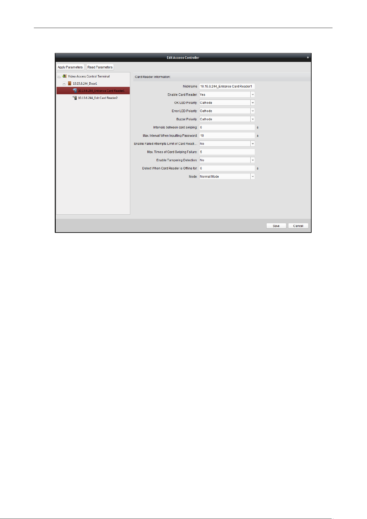
Editing Card Reader Information
Steps:
1. In the device list on the left, click to expand the door, select the card reader name and you can edit the
card reader information on the right.
Page 29
Video Access Control Terminal User Manual
24
2. You can editing the following parameters:
Enable Card Reader: Select Yes to enable the card reader.
OK LED Polarity: Select the OK LED Polarity of the card reader mainboard.
Error LED Polarity: Select the Error LED Polarity of the card reader mainboard
Buzzer Polarity: Select the Buzzer LED Polarity of the card reader mainboard
Interval between Card Swiping: If the interval between card swiping of the same card is less than the set value,
the card swiping is invalid. You can set it as 0 to 255.
Max. Interval When Inputting Password: When you inputting the password on the card reader, if the interval
between pressing two digits is larger than the set value, the digits you pressed before will be cleared
automatically.
Enable Failed Attempts Limit of Card Reading: Enable to report alarm when the card reading attempts reach
the set value.
Max. Times of Card Swiping Failure: Set the max. failure attempts of reading card.
Enable Tampering Detection: Enable the anti-tamper detection for the card reader.
Detect When Card Reader is Offline for: When the access control device cannot connect with the card reader
for longer than the set time, the card reader will turn offline automatically.
Mode: Select the card reader mode as normal mode (reading card) or issuing card mode (getting the card No.).
3. Click the Save button to save parameters.
4. Click Apply Parameters button to apply the updated parameters to the local memory of the device.
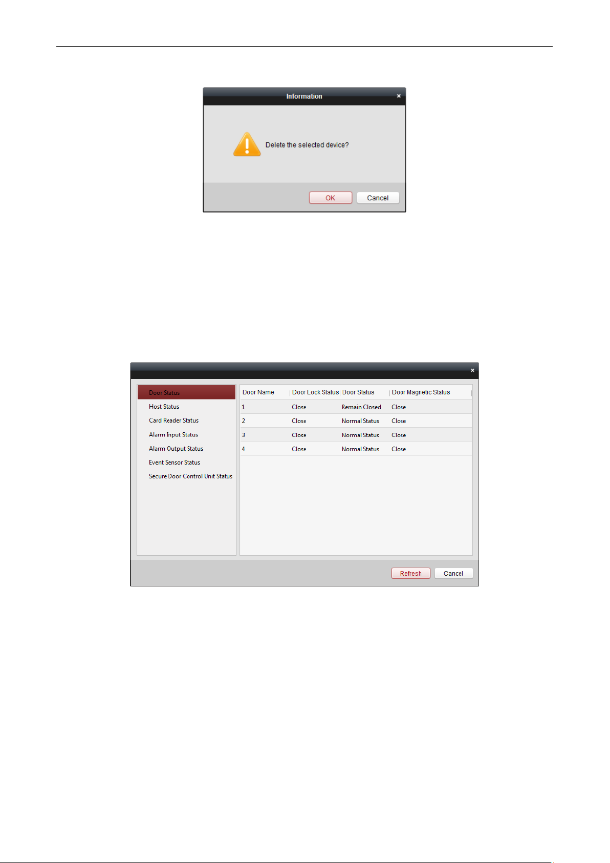
Deleting Device
Steps:
1. In the device list, click to select a single device, or select multiple devices by pressing Ctrl button on your
keyboard and clicking them one by one.
2. Click Remove button to delete the selected device(s).
3. Click OK button in the pop-up confirmation dialog to finish deleting.
Page 30
Video Access Control Terminal User Manual
25
Time Synchronization
Steps:
1. In the device list, click to select a single device, or select multiple devices by pressing Ctrl button on your
keyboard and clicking them one by one.
2. Click Synchronization button to start time synchronization.
A message box will pop up on the lower-right corner of the screen when the time synchronization is
compeleted.
Viewing Device Status
In the device list, you can select the device and then click Status button to enter view its status.
Door Status: The status of the connected door.
Host Status: The status of the host, including Storage Battery Power Voltage, Device Power Supply Status, Multi-
door Interlocking Status, Anti-passing Back Status, and Host Anti-Tamper Status.
Card Reader Status: The status of card reader.
Alarm Input Status: The alarm input status of each port.
Alarm Output Status: The alarm output status of each port.
Event Sensor Status: The event status of each port.
Secure Door Control Unit Status: The online status and tamper status of the Secure Door Control Unit.
Remote Configuration
Purpose:
In the device list, select the device and click Remote Configuration button to enter the remote configuration
interface. You can set the detailed parameters of the selected device.
Page 31

Video Access Control Terminal User Manual
26
Checking Device Information
Steps:
1. In the device list, you can click Remote Configuration to enter the remote configuration interface.
2. Click System -> Device Information to check the device basic information and the device version
information.
Editing Device Name
In the Remote Configuration interface, click System -> General to configure the device name and overwrite
record files parameter. Click Save to save the settings.
Editing Time
Steps:
1. In the Remote Configuration interface, click System -> Time to configure the time zone.
2. (Optional) Check Enable NTP and configure the NTP server address, the NTP port, and the synchronization
interval.
3. (Optional) Check Enable DST and configure the DST star time, end time and the bias.
Page 32

Video Access Control Terminal User Manual
27
4. Click Save to save the settings.
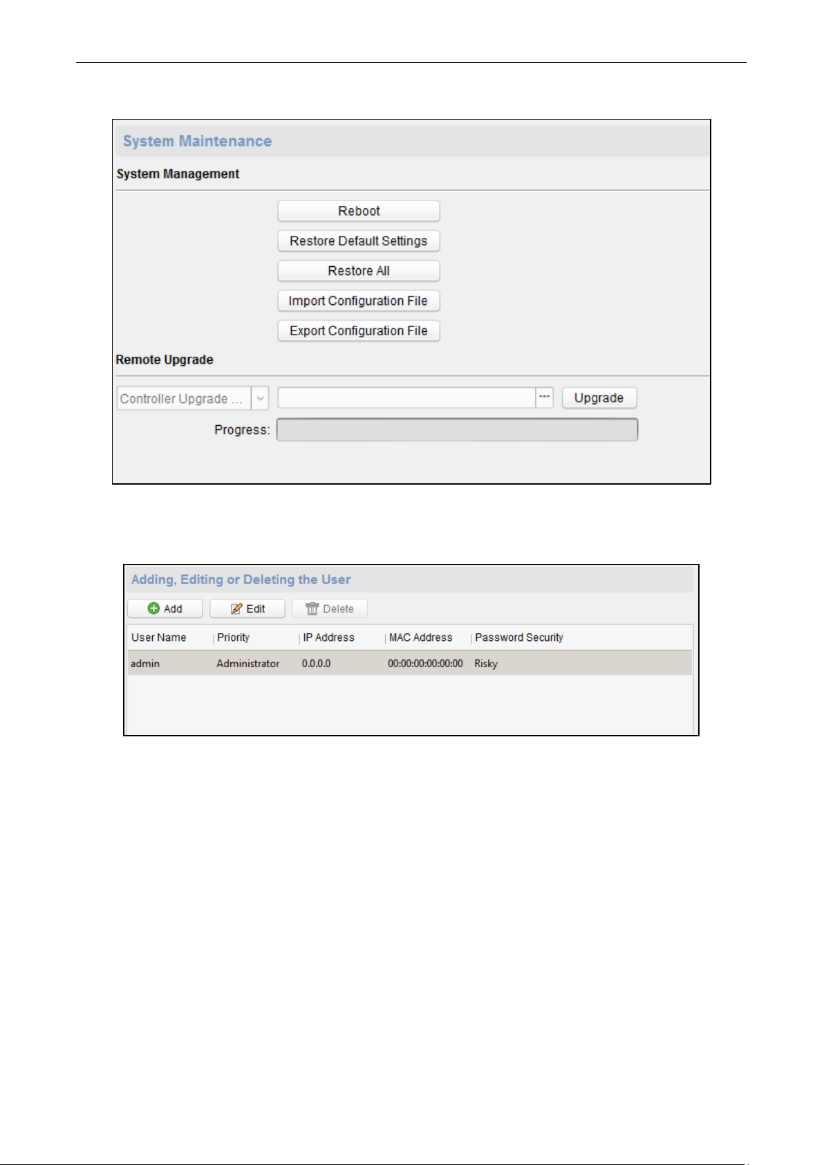
System Maintenance Settings
Steps:
1. In the Remote Configuration interface, click System -> System Maintenance.
2. Click Reboot to reboot the device.
Or click Restore Default Settings to restore the device settings to the default ones, excluding the IP address.
Or click Restore All to restore the device parameters to the default ones. The device should be activated
after restoring.
Or click Import Configuration File to import the configuration file from the local PC to the device.
Or click Export Configuration File to export the configuration file form the device to the local PC.
The configuration file contains the device parameters.
3. In the Remote Upgrade part, select a upgrade file type in the dropdown list. Click to select the upgrade
file. Click Upgrade to start upgrading.
You are able to select Controller Upgrade File, Card Reader Upgrade File and Distributed Controller Upgrade
File in the drop-down list.
Page 33
Video Access Control Terminal User Manual
28
Managing User
Steps:
1. In the Remote Configuration interface, click System -> User.
2. Click Add to add the user (Do not support by the elevator controller.).
Or select a user in the user list and click Edit to edit the user. You are able to edit the user password, the IP
address, the MAC address and the user permission. Cilck OK to confirm editing.
Page 34

Video Access Control Terminal User Manual
29
Setting Security
Steps:
1. Click System -> Security.
2. Select the encryption mode in the dropdown list. You are able to select Compatible Mode or Encryption
Mode.
3. (Optional) You can check Enable SSH or Enalbe Illegal Login Lock in the Software part.
4. Click Save to save the settings.
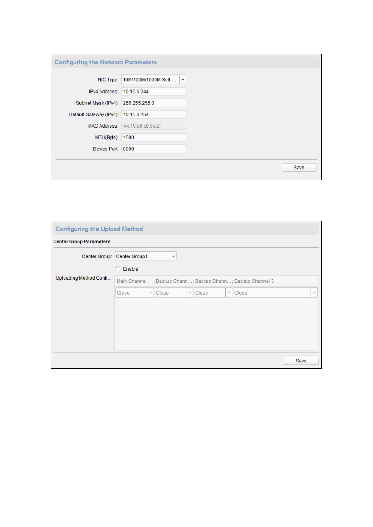
Configuring Network Parameters
Click Network -> General. You can configure the NIC type, the IPv4 address, the subnet mask (IPv4), the default
gateway (IPv4), MTU address, the MTU, and the device port. Click Save to save the settings.
Page 35
Video Access Control Terminal User Manual
30
Confiugring Upload Method
Steps:
1. Click Network -> Uploading Method Settings.
2. Select a Center Group from the drop-down list.
3. Check the Enable check box and set the uploading method.
4. Click Save to save the settings.
Configuring Network Center Parameters
Click Network -> Network Center Settings. You can set the notify surveillance center, the IP addres, the port No.
the protocol type and the user name. Click Save to save thesettings.
Page 36

Video Access Control Terminal User Manual
31
Configuring Avdanced Network
Click Network -> Advanced Settings. You can configure the DNS address 1, the DNS address 2, the alarm host IP
and the alarm host port. Click Save to save the settings.
Configuring Wi-Fi Parameter
Step:
1. Click Network -> Wi-Fi.
Page 37

Video Access Control Terminal User Manual
32
2. Check the Enable checkbox to enable the Wi-Fi function.
You can set the hot spot name and the password. Click Select to select the hot sport. Click Refresh to
refresh the Wi-Fi staus.
You can also set the NIC type.
Check the Enable DHCP checkbox to auto allocate the IP address, the subnet mask, the default gateway, the
MAC address the DNS1 IP address and the DNS2 IP address.
3. Click Save to save the settings.
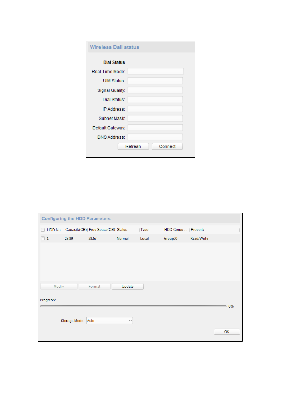
Configuring Wireless Dail Status
Steps:
1. Click Network -> Wireless Dial.
Page 38
Video Access Control Terminal User Manual
33
2. Edit the dial status, including the real-time mode, the UIM status, the signal quality, the dial status, the IP
address, the subnet mask the default gateway and the DNS address.
3. Click Conenct to start connecting.
Or click Refresh to refresh the status.
Configuring HDD Parameters
Steps:
1. Click Storage -> General.
2. Check the HDD (SD card) No., capacity, the free space, the status and so on.
You can also edit and format the HDD (SD card). Or click Update to refresh the data.
Page 39

Video Access Control Terminal User Manual
34
3. Select the storage mode.
4. Click Save to save the settings.
Configuring Trigger Parameters
Steps:
1. Click Alarm -> Trigger. You can check the trigger parameters.
2. Click the icon to enter the Trigger Parameters Settings window. You can configure the trigger name and
the output delay.
3. Click Save to save the paramters.
4. (Optional) Click Copy to… to copy the trigger information to other triggers.
Configuring Access Control
In the Remote Configuration interface, click Other -> Access Control Parameters. Check Superimposed user
information, Enable voice prompts, Upload picture to capture whether the linkage, Save Linked Captured
Pictures, Whether to allow key input card number, Enable WiFi detect, and Enable 3G/4G. Click Save to save
the settings.
Page 40
Video Access Control Terminal User Manual
35
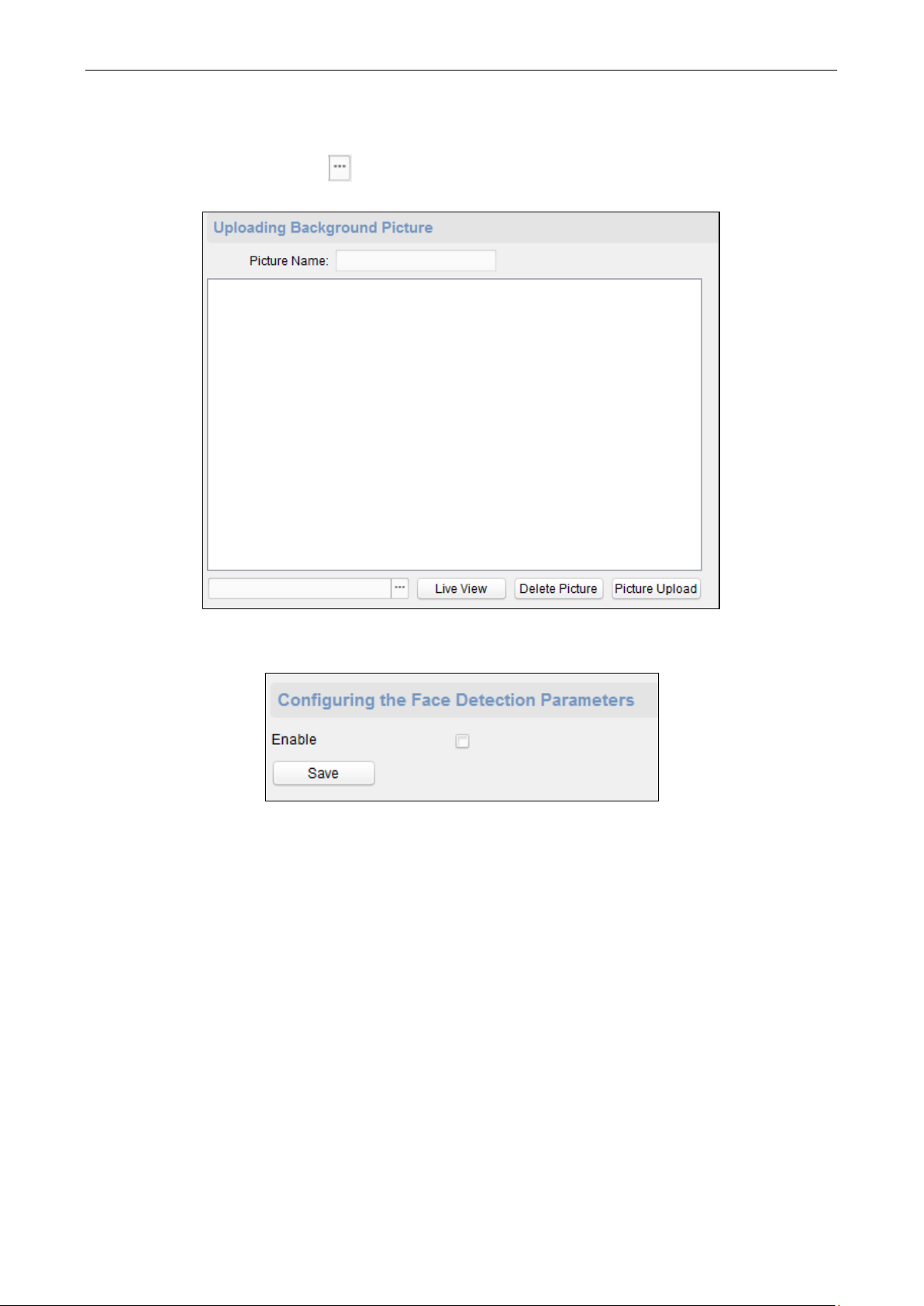
Uploading Backgroup Picture
Click Other -> Picture Upload. Click to select the picture from the local. You can also click Live View to
preview the picture. Click Picture Upload to upload the picture.
Configuring Face Detection Parameters
Click Other -> Face Detection. You can check the Enable checkbox to enable the device face detection function.
Configuring Video and Audio Parameters
You can set the video compression parameters.
Steps:
1. Click Image -> Video & Audio.
Page 41

Video Access Control Terminal User Manual
36
2. Select a camera in the drop-down list.
3. Set the camera video parameters, including the stream type, the bitrate type, the video quality, the frame
type , the I frame type, the video encoding type, the video type, the bitrate, the resolution, the frame rate
and the audio encoding type.
4. Click Save to save the settings.
Or click Copy to… to copy the parameters to other cameras.
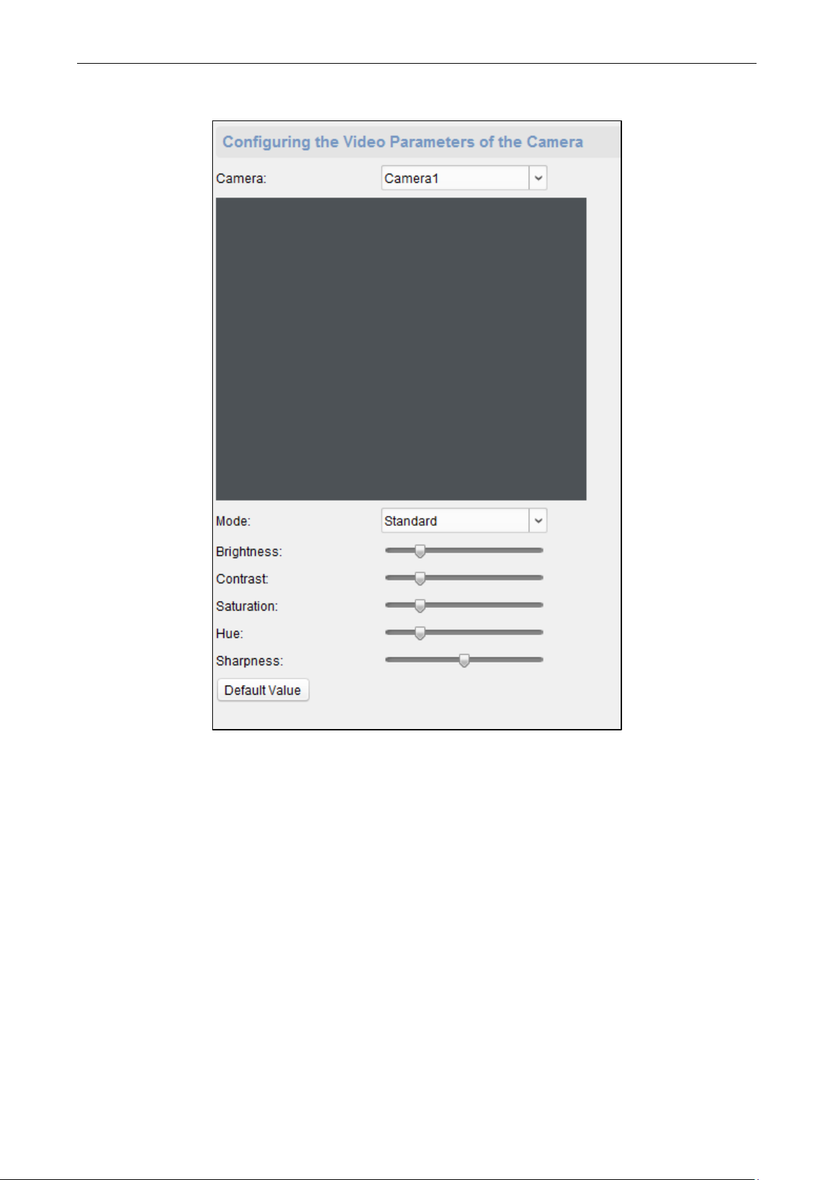
Configuring Video Image Parameters
You can set the camera mode, brightness, contrast, saturation, hue, and sharpness.
Steps:
1. Click Image -> Image Settings.
Page 42
Video Access Control Terminal User Manual
37
2. Select a camera in the dropdown list.
3. Set the camera mode, brightness, contrast, saturation, hue, and sharpness.
Or click Default Value to set the parameters to the default values.
Configuring Volume Input and Output
Click Image -> Volume Input/Output. You can set the volume input and output. Click Save to save the settings.
Page 43

Video Access Control Terminal User Manual
38
Operating Trigger
Steps:
1. Click Operation -> Trigger. You can check the trigger status.
2. Check the trigger and click Open or Close to open/close the trigger.
Checking Status
Click Status -> Alarm or Status -> Trigger to check the trigger status.
7.2.2 Network Settings
In the Edit Access Controller interface, select the access control device and click Network Settings button to
enter the Network Settings interface. You can set the uploading mode, and set the network center and wireless
communication center.
Uploading Mode Settings
Steps:
1. Click the Uploading Mode Settings tab.
Page 44

Video Access Control Terminal User Manual
39
2. Select the center group in the dropdown list.
3. Check the Enable checkbox to enable the selected center group.
4. Select the report type in the dropdown list.
5. Select the uploading mode in the dropdown list. You can enable N1/G1 for the main channel and the backup
channel, or select off to disable the main channel or the backup channel.
Note: The main channel and the backup channel cannot enable N1 or G1 at the same time.
6. Click Save button to save parameters.
Network Center Settings
You can set the account for EHome protocol in Network Settings tab page. Then you can add devices via EHome
protocol.
Steps:
1. Click the Network Center Settings tab.
2. Select the center group in the dropdown list.
3. Select an address type in the dropdown list.
4. Input IP address and port No. For EHome protocol, the default port No. for EHome is 7660.
5. Select the protocol type as EHome.
6. Set an account name for the network center.
Note: The account should contain 1 to 32 characters and only letters and numbers are allowed.
7. Click Save button to save parameters.
Page 45

Video Access Control Terminal User Manual
40
Note: The port number of the wireless network and wired network should be consistent with the port number of
EHome.
Wireless Communication Center Settings
Steps:
1. Click the Wireless Communication Center Settings tab.
2. Select the APN name as CMNET or UNINET.
3. Input the SIM Card No.
4. Select the center group in the dropdown list.
5. Input the IP address and Port No.
6. Select the protocol type as EHome. The default port No. for EHome is 7660.
7. Set an account name for the network center. A consistent account should be used in one platform.
8. Click Save button to save parameters.
Note: The port number of the wireless network and wired network should be consistent with the port number of
EHome.
7.2.3 Capture Settings
In the Edit Access Controller interface, select the access control device and click Capture Settings button to enter
the capture settings interface. You can set the parameters of capture linkage and manual capture.
Notes:
The Capture Settings should be supported by the device.
Before setting the capture setting, you should configure the storage server for picture storage. For details,
refer to 8.4.4 Storage Server Configuration.
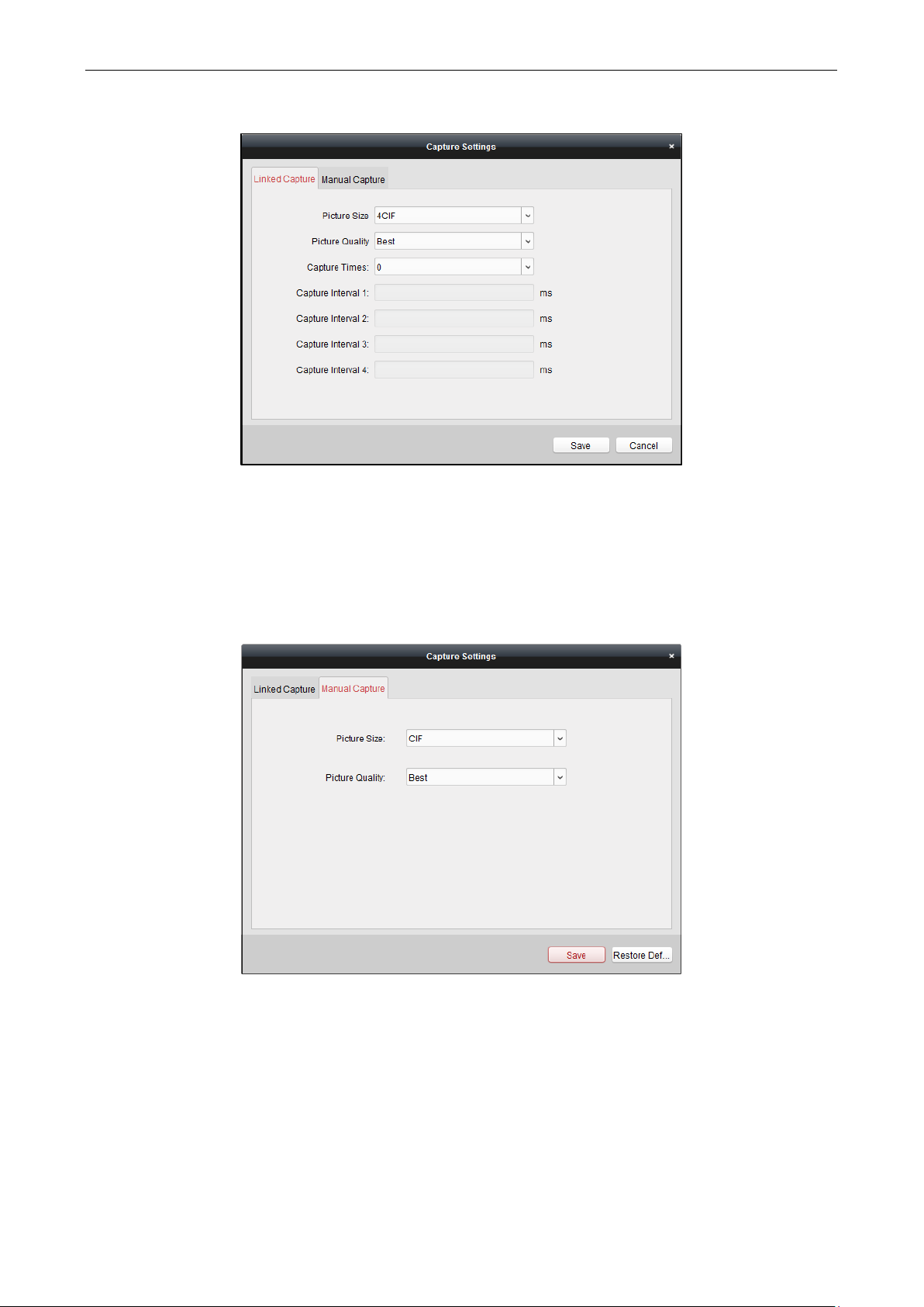
Linked Capture
Steps:
1. Select the Linked Capture tab.
Page 46
Video Access Control Terminal User Manual
41
2. Set the picture size and quality.
Set the linked capture times once triggered
Set the capture interval according to the capture times.
3. Click Save to save the settings.
Manual Capture
Steps:
1. Select the Manual Capture tab.
2. Select the resolution of the captured pictures from the dropdown list.
Note: The supported resolution types are CIF, QCIF, 4CIF/D1, SVGA, HD720P, VGA, WD1, and AUTO.
3. Select the picture quality as Best, Better, or Normal.
4. Click Save to save the settings.
5. You can click Restore Default Value to restore the parameters to default settings.
7.2.4 RS-485 Settings
Purpose:
Page 47
Video Access Control Terminal User Manual
42
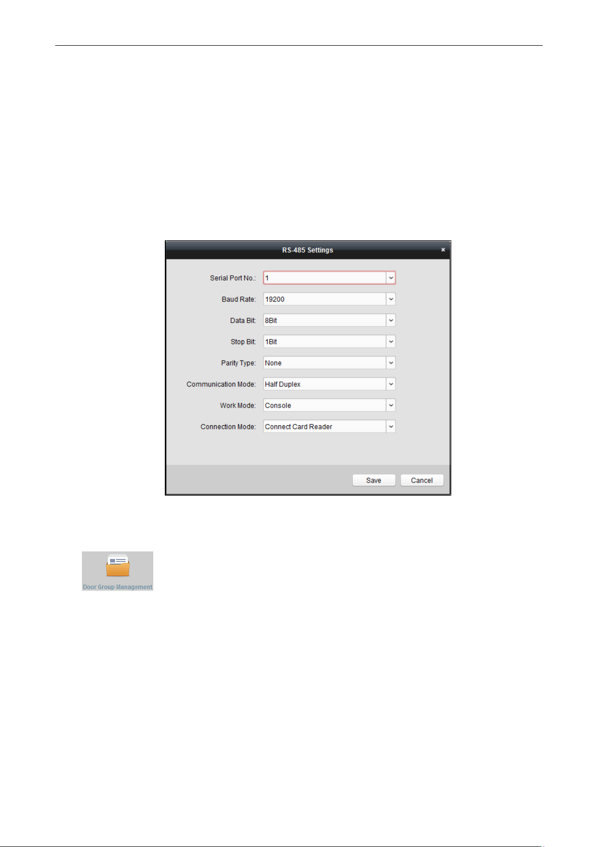
You can set the RS-485 parameters including the baud rate, data bit, the stop bit, parity type, flow control type,
communication mode, work mode, and connection mode.
Note: The RS-485 Settings should be supported by the device.
Steps:
1. In the Edit Access Controller interface, select the access control device and click the RS-485 Settings button to
enter the RS-485 Settings interface.
Note: The RS-485 Settings button is available when the device supports RS-485 port.
2. Select the serial No. of the port from the dropdown list to set the RS-485 parameters.
3. Set the baud rate, data bit, the stop bit, parity type, communication mode, work mode, and connection mode
in the dropdown list.
4. Click Save to save the settings and the configured parameters will be applied to the device automatically.
7.2.5 Door Group Management
After adding the access control device, you can add the access control points (doors ) to different groups to
realize the centralized management.
Click icon on the control panel to enter the Door Group Management interface.
Page 48

Video Access Control Terminal User Manual
43
The interface is divided into two parts: Group Management area and Access Control Point Management area.
Group Management
The access control points can be added to different groups to realize the centralized management.
Access Control Point Management
Manage the specific access control point (door) under the group, including importing, editing and deleting
access control point.
Access Control Group Management
Adding Group
Before you can manage the doors, you need to create groups first.
Steps:
1. Click Add Group button on the left to pop up the Add Group dialog.
2. Input the group name in the text field and click OK button to finish adding.
Editing Group
After adding the group, you can move the mouse to the group name and click to pop up the Edit Group
dialog box.
Or you can double click the group to edit the group name.
Deleting Group
You can move the mouse to the group name and click to delete the selected group.
Or you can click to select the group and click Delete Group to delete it.
Page 49

Video Access Control Terminal User Manual
44
Note: All the access control points in the group will be deleted.
Access Control Point (Door) Management
After adding the group, you can import the access control point of the added access control device to the group.
Importing Access Control Point
Steps:
1. Select the added group, and click Import button to pop up the access control point importing interface as
follows.
2. Select the access control point to import from the access control point list on the left.
3. Select an added group to import the access control point on the right.
4. Click Import button to import the selected access control points or you can click Import All to import all the
available access control points to the selected group.
5. (Optional) You can click button on the upper-right corner of the window to create a new group.
Move the mouse to the added group or access control point and click or to edit or delete it.
Note: Up to 64 access control points can be imported to the door group.
Editing Access Control Point
Steps:
1. Check the checkbox to select the imported access control point in the list and click Edit button to edit the
access control point.
2. You can edit the access control point name and the position.
3. You can view the card reader under the selected access control point.
4. Click OK to save the settings.
Deleting Access Control Point
Check the checkbox to select the imported access control point and click Delete button to delete the selected
access control point.
Page 50

Video Access Control Terminal User Manual
45
7.3 Permission Configuration
You can add the department and person to the client for management, and add card for access control. You can
set the schedule template and configure the access control permission via the client.
7.3.1 Person Management
Click icon on the control panel to enter the Person Management interface.
You can add, edit, and delete the department and person in Person Management module.
The interface is divided into two parts: Department Management and Person Management.
Department Management
You can add, edit, or delete the department as desired.
Person Management
After adding the department, you can add the person to the department for further management.
Department Management
Adding Department
Steps:
1. In the department list on the left, the Default Department already exists in the client as the parent department
of all departments.
2. Select the upper department and click Add Department button to pop up the adding department interface to
add the lower department.
Page 51

Video Access Control Terminal User Manual
46
3. Input the Department Name as desired.
4. Click OK to save the adding.
Notes:
You can add multiple levels of departments according to the actual needs. Click a department as the upper-
level department and click Add Department button, and then the added department will be the sub-
department of it.
Up to 10 levels can be created.
Editing and Deleting Department
You can double-click the added department to edit its name.
You can click to select a department, and click Delete Department button to delete it.
Notes:
The lower-level departments will be deleted as well if you delete a department.
Make sure there is no person added under the department, or the department cannot be deleted.
Person Management
After adding the department, you can add person to the department and manage the added person such as
issuing card in batch, importing and exporting person information in batch, etc..
Note: Up to 2000 persons can be added.
Adding Person (Basic Information)
Steps:
1. Select a department in the department list and click Add Person to pop up the adding person interface.
2. Click Basic Information tab to input the person’s basic information.
3. The Person No. will be generated automatically and is not editable.
Page 52

Video Access Control Terminal User Manual
47
4. Input the basic information including person name, gender, ID type, ID No., contact No., and address.
5. Click Upload Picture to select the person picture from the local PC to upload it to the client.
Note: The picture should be in *.jpg, or *.jpeg format.
6. Click OK to finish adding.
Adding Person (Fingerprint)
Before inputting the fingerprint, you should connect the fingerprint machine to the PC and set its parameters
first. For details, refer to 8.4.3 Fingerprint Machine Configuration.
Steps:
1. In the Add Person interface, click Fingerprint tab.
2. Click Start button, click to select the fingerprint to start collecting.
3. Lift and rest the corresponding fingerprint on the fingerprint scanner twice to collect the fingerprint to the
client.
You can click Collect from Device and select the device to scan fingerprint.
You can select the registered fingerprint and click Delete Fingerprint to delete it.
You can click Delete All to clear all fingerprints.
4. Click OK to save the fingerprints.
Editing and Deleting Person
You can double-click the added person to edit its basic information and fingerprint.
Or you can check the checkbox to select the person and click Edit Person to edit it.
You can click to select a person, and click Delete Person to delete it.
Note: If a card is associated with the current person, the association will be invalid after the person is deleted.
Importing and Exporting Person Information
The person information can be imported and exported in batch.
Steps:
1. After adding the person, you can click Export Person button to export all the added person information to
the local PC including person No., person name, gender, ID type, ID No., Department, telphone No., and
contact address.
Page 53

Video Access Control Terminal User Manual
48
Click to select the path of saving the exported Excel file.
Click OK to start exporting.
2. To import the Excel file with person information in batch from the local PC, click Import Person button.
You can click Download Person Importing Template to download the template first.
Input the person information to the downloaded template.
Click to select the Excel file with person information.
Click OK to start importing.
Getting Person Information from Access Control Device
If the added access control device has been configured with person information (including person details,
fingerprint, issued card information), you can get the person information from the device and import to the
client for further operation.
Note: This function is only supported by the device the connection mothod of which is TCP/IP when adding the
device.
Steps:
4. In the department list on the left, click to select a department to import the persons to.
5. Click Get Person button to pop up the following dialog box.
6. The added access control device will be displayed.
7. Click to select the device and then click OK to start getting the person information from the device.
You can also double click the device name to start getting the person information.
Notes:
Page 54

Video Access Control Terminal User Manual
49
The person information, including person details, person’s fingerprint information (if configured), and the
linked card (if configured), will be imported to the selected department.
After getting the person information, if the person has issued card, the card information will be added to the
Card Managment module of the client as well.
If the person name stored in the device is empty, the person name will be filled with the issued card No.
after importing to the client.
The gender of the persons will be Male by default.
Importing Person Picture
After adding the person information to the client, you can also import person picture to the client in batch.
Before you start:
The person pictures to import should be named after the corresponding person No. As a result, you can export
the persons information to get the No. of the persons first.
After naming the pictures after the person No., you can import the pictures in batch.
Steps:
1. Click Import Picture button to pop up the Import Picture dialog box..
2. Click to select the package with person pictures and click OK to start importing.
Notes:
The picture name should be the same with the person’s person No..
Each picture should be less than 2 MB and should be in .jpg format.
The package file should be .zip file.
The package file should be less than 100 MB.
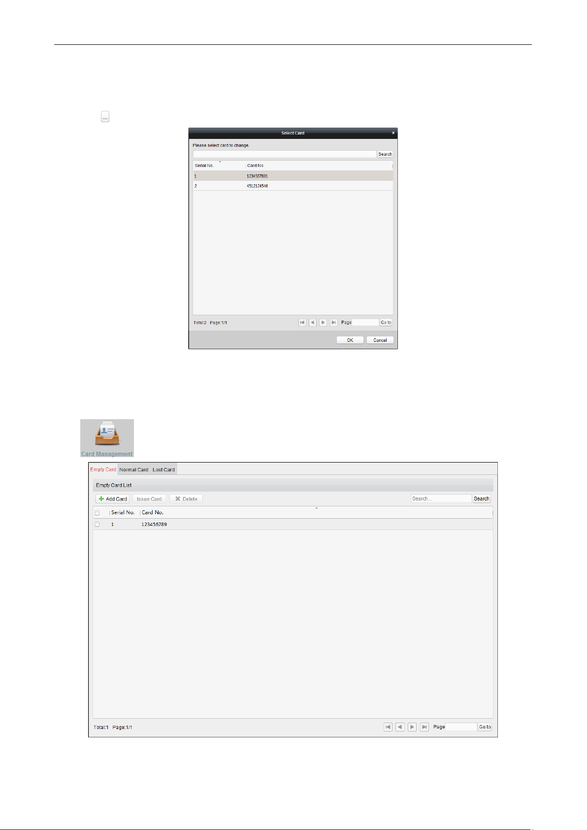
Card Operation
After adding the person and card, you can select the person and click in the Card field for further operation
such as issuing card, changing card No., , reporting card loss, card replacement, and returning card.
Page 55

Video Access Control Terminal User Manual
50
You can click More to view the person details.
For details about these operation, please refer to Chapter 4.2 Card Management.
Issuing Card in Batch
After adding the card information to the client, you can issuing card for the person in batch. For details about
adding the card, please refer to 4.2 Card Management.
Steps:
1. Check the checkbox to select the person for issuing card.
2. Click Issur Card in Batch button to enter the following interface.
3. Click to set the effective time and expiry time of the card. Click OK to save the time settings.
Page 56
Video Access Control Terminal User Manual
51
4. In the person list, you can view the selected person details including person name, department, and
telephone number.
Click to select card to be issued to the person.
Select the card from the card list and click OK to save the settings.
You can input the card No. and click Search button to search the card.
5. Click OK to complete the card issuing.
7.3.2 Card Management
Click on the control panel to enter the card management interface.
Page 57

Video Access Control Terminal User Manual
52
There are three card types: Empty Card, Normal Card, and Lost Card.
Empty Card: A card has not been issued with a person.
Normal Card: A card is issued with a person and is under normal using.
Lost Card: A card is issued with a person and is reported as lost.
Empty Card
Click Empty Card tab to manage the empty card first.
Adding Card
Before you start:
When inputting the card No. when adding the card, you can get the card No. via the following two ways:
You can get the card No. by the connected card reader. Make sure a card reader is connected to the PC and
is configured already. Refer to 8.4.2 Card Reader Configuration for details.
You can also get the card No. by scanning the card on the card reader of the access control device. For this
situation, please set the mode as Card Reader Mode in Editing Access Controller. For details, refer to 3.1.4
Editing Access Control Device.
The detected card No. will be inputted in the Card No. field automatically.
Perform the following steps to add empty card.
Steps:
1. Click Add Card button to pop up the Add Card dialog box.
2. Two adding methods are supported.
Adding Single Card
Select Single Adding as the adding mode and input the card No..
Note: Up to 20 characters are allowed in the card No., including digits or letters.
Batch Adding Cards
Select Batch Adding as the adding mode. Input the start card No. and the end card No..
Notes:
The start card No. and the last card No. should be the with same length. E.g., the last card No. is 234,
then the start card No. should be like 028.
For batch adding, the card No. should contain 1 to 10 digits and letters are not allowed.
Page 58

Video Access Control Terminal User Manual
53
3. Click OK button to finish adding.
4. You can check the checkbox of the added card and click Delete to delete the card.
Issuing Card
After adding the card to the client, you can issue it to the corresponding added person. You can also issuing the
cards to persons in batch. For details, refer to 4.1.2 Person Management.
Steps:
1. Click an added empty card in the list and click Issue Card button to issue the card with a person.
You can also double click the empty card in the card list to enter the Issue Card interface as follows.
2. Input the password of the card itself. The card password should contain 4 to 8 digits.
Note: The password will be required when the card holder swiping the card to get enter to or exit from the
door if you enable the card reader authentication mode as Card and Password, Password and Fingerprint,
and Card, Password, and Fingerprint. For details, refer to 4.7.2 Card Reader Authentication.
3. Click to set the effective time and expiry time of the card. Click OK to save the time settings.
4. Click to select a person and select a fingerprint for the card.
Note: To select the person’s fingerprint, you are required to import the fingerprint first. For details, refer to
4.1.2 Person Management.
Page 59

Video Access Control Terminal User Manual
54
5. Click OK to finish issuing card.
Notes:
The issued card will disappear from the Empty Card list, and you can check the card information in the Normal
Card list.
Up to 2000 cards can be added.
Normal Card
After adding the empty card to the client and issue the card to the person, the card will be displayed in the
Normal Card list.
Click Normal Card tab in the card managemet interface to show the Normal Card list. You can view all the issued
card information, including card No., card holder, and the department of the card holder.
Editing Card
You can double click the normal card in the list to edit the card linked person information.
You can edit the card effective time and expiry time, and you can change the person and select the
conrresponding fingerprint to issue the card again.
Note: To select the person’s fingerprint, you are required to import the fingerprint first. For details, refer to 4.1.2
Person Management.
Changing Card
You can change the linked card for the card holder.
Steps:
1. Check the checkbox to select a normal card and click Change Card button to change the associated card for
card holder.
Page 60
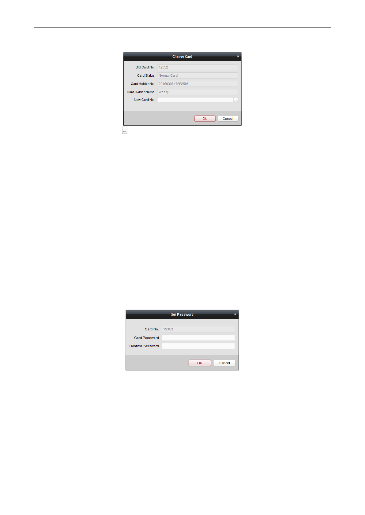
Video Access Control Terminal User Manual
55
2. In the pop-up window, click and select another card in the popup window to replace the current card.
3. Click OK to save the changes.
Note: After changing the card, the original card will turn to empty card and you can find it in the Empty Card tab
page.
Returning Card
You can return the card from normal card to empty status and cancel the linkage between the card and the
person.
Steps:
1. Check the checkbox to select an issued card and click Return Card button to cancel the assotiation of the
card.
2. Click OK to comfirm the operation.
Then the card will disappear from the Normal Card list, and you can find it in the Empty Card list.
Reporting Card Loss
Steps:
1. Check the checkbox to select an issued card and click Report Card Loss button to set the card as the Lost Card,
that is, an invalid card.
2. Click OK to comfirm the operation.
Then the card will disappear from the Normal Card list, and you can find it in the Lost Card list.
Setting Card Password
Steps:
1. Check the checkbox to select an issued card and click Set Password button to set the password for the card.
2. Input the card password and confirm the password. The card password should contain 4 to 8 digits.
3. Click OK to save the settings.
Note: The password will be required when the card holder swiping the card to get enter to or exit from the door
if you enable the card reader authentication mode of Card and Password, Password and Fingerprint, and Card,
Password, and Fingerprint. For details, refer to 4.7.2 Card Reader Authentication.
Importing and Exporting Cards
Steps:
1. To import the card and person information from the local PC, click Import button to pop up the following
dialog box.
Page 61
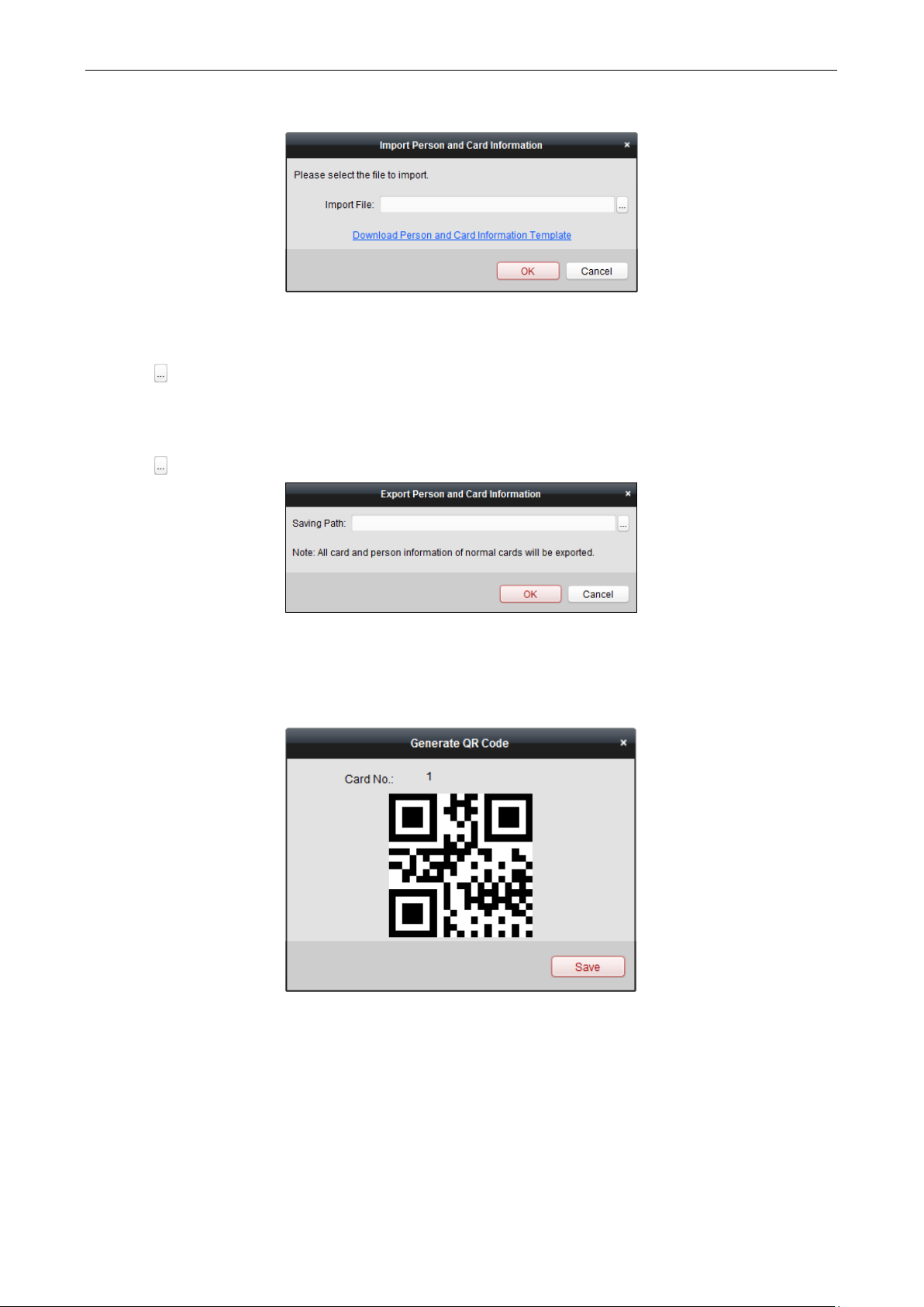
Video Access Control Terminal User Manual
56
Click Download Person and Card Infotmation Template to download the template for importing.
In the template file, input the card holder name and the corresponding card No..
Note: The Card No. should be 1 to 20 digits
Click to select the template file with card and person information.
Click OK to start importing.
2. To export all the normal card information to the local PC, click Export button to pop up the following dialog
box.
Click to select the path to save the exported file.
Click OK to start exporting. All the normal cards with card holder name and card No. will be exported to the
Excel file.
Saving QR Code Picture
Steps:
1. Click the QR code button in the Normal Card list.
2. Click Save in the pop-up QR code window.
3. Select the saving path in the pop-up window.
4. Click OK to save the picutre.
Lost Card
You can manage the card which is reported as lost, including canceling card loss and replacing card.
Click Lost Card tab in the card managemet interface to show the Lost Card list. You can view all the lost card
information, including card No., card holder, and the department of the card holder.
Page 62

Video Access Control Terminal User Manual
57
Canceling Card Loss
If the lost card is found, you can cancel the loss for the card and the lost card will turn to normal card.
Steps:
1. Check the checkbox to select the lost card in the list.
2. Click Cancel Card Loss button to resume the card to the normal card.
3. Click OK to confirm the operation.
Card Replacement
If the lost card cannot be found any more, you can replace the lost card with a new card.
Steps:
1. Check the checkbox to select the lost card in the list.
2. Click Replace Card button to issue a new card to the card holder replacing for the lost card.
3. Click button to select another card in the popup window as the new card and the predefined permissions
of the lost card will be copied to the new one automatically.
4. Click OK to save the changes.
7.3.3 Schedule Template
Purpose:
You can configure the schedule template including week schedule and holiday schedule. After setting the
templates, you can adopt the configured templates to access control permissions when setting the permission,
so that the access control permission will take effect in the time durations of the schedule template.
Click on the control panel to enter the schedule template interface.
Page 63

Video Access Control Terminal User Manual
58
You can manage the schedule of access control permission including Week Schedule, Holiday Schedule, and
Template. For permission settings, please refer to 4.6 Permission Configuration.
Week Schedule
Click Week Schedule tab to enter the Week Schedule Management interface.
The client defines two kinds of week plan by default: Whole Week Schedule and Blank Schedule, which cannot
be deleted and edited.
Whole Week Schedule: Card swiping is valid on each day of the week.
Blank Schedule: Card swiping is invalid on each day of the week.
You can define custom schedules on your demand.
Steps:
1. Click button to pop up the adding schedule interface.
2. Input the name of week schedule and click OK button to add the week schedule.
3. Select the added week schedule in the schedule list on the left and you can view its property on the right.
4. You can edit the week schedule name and input the remark information.
5. On the week schedule, click and drag on a day to draw on the schedule, which means in that period of time,
the configured permission is activated.
Note: Up to 8 time periods can be set for each day in the schedule.
6. When the cursor turns to , you can move the selected time bar you just edited. You can also edit the
displayed time point to set the accurate time period.
Page 64

Video Access Control Terminal User Manual
59
When the cursor turns to , you can lengthen or shorten the selected time bar.
7. Optionally, you can select the schedule time bar,
and then click Delete Duration to delete the selected time bar,
or click Clear to delete all the time bars,
or click Copy to Week to copy the time bar settings to the whole week.
8. Click Save to save the settings.
Holiday Group
Click Holiday Group tab to enter the Holiday Group Management interface.
Steps:
1. Click Add Holiday Group button on the left to pop up the adding holiday group interface.
2. Input the name of holiday group in the text filed and click OK button to add the holiday group.
3. Select the added holiday group and you can edit the holiday group name and input the remark information.
4. Click Add Holiday icon on the right to add a holiday period to the holiday list and configure the duration of the
holiday.
Note: Up to 16 holidays can be added to one holiday group.
Page 65

Video Access Control Terminal User Manual
60
1) On the period schedule, click and drag to draw the period, which means in that period of time, the
configured permission is activated.
Note: Up to 8 time durations can be set for each period in the schedule.
2) When the cursor turns to , you can move the selected time bar you just edited. You can also edit the
displayed time point to set the accurate time period.
3) When the cursor turns to , you can lengthen or shorten the selected time bar.
4) Optionally, you can select the schedule time bar,
and then click to delete the selected time bar,
or click to delete all the time bars of the holiday,
or click to delete the holiday directly.
5. Click Save to save the settings.
Note: The holidays cannot be overlapped with each other.
Schedule Template
After setting the week schedule and holiday group, you can configure the schedule template which contains
week schedule and holiday group schedule.
Note: The priority of holiday group schedule is higher than the week schedule.
Click Schedule Template tab to enter the Schedule Template Management interface.
Page 66

Video Access Control Terminal User Manual
61
There are two pre-defined templates by default: Whole Week Template and Blank Template, which cannot be
deleted and edited.
Whole Week Template: The card swiping is valid on each day of the week and it has no holiday group
schedule.
Blank Template: The card swiping is invalid on each day of the week and it has no holiday group schedule.
You can define custom templates on your demand.
Steps:
1. Click Add Template to pop up the adding template interface.
2. Input the template name in the text filed and click OK button to add the template.
3. Select the added template and you can edit its property on the right. You can edit the template name and
input the remark information.
4. Select a week schedule to apply to the schedule.
Click Week Schedule tab and select a schedule in the dropdown list.
You can also click Add Week Schedule to add a new week schedule. For details, refer to 4.3.1 Week Schedule.
Page 67

Video Access Control Terminal User Manual
62
5. Select holiday groups to apply to the schedule.
Note: Up to 4 holiday groups can be added.
Click to select a holiday group in the list and click Add to add it to the template. You can also click Add Holiday
Group to add a new one. For details, refer to 4.3.2 Holiday Group.
You can click to select an added holiday group in the right-side list and click Delete to delete it.
You can click Clear to delete all the added holiday groups.
6. Click Save button to save the settings.
7.3.4 Door Status Management
Purpose:
You can anti-control the door via the client and set the door status duration.
Page 68

Video Access Control Terminal User Manual
63
Click icon on the control panel to enter the Status Monitor interface.
Anti-control the Access Control Point (Door)
Purpose:
You can control the status for a single access control point (a door).
Steps:
1. Select an access control group on the left. For managing the access control group, refer to 3.6.1 Access Control
Group Management.
2. The access control points of the selected access control group will be displayed on the right.
Click icon on the Status Information panel to select a door.
3. Click the following button listed on the Status Information panel to control the door.
: Click to open the door once.
: Click to close the door once.
: Click to keep the door open.
: Click to keep the door closed.
: Click to capture the picture manually.
4. You can view the anti-control operation result in the Operation Log panel.
Notes:
If you select the status as Remain Open/Remain Closed, the door will keep open/closed until a new anti-
control command being made.
The Capture button is available when the device supports capture function. And it cannot be realized until
the storage server is configured. Refer to 8.4.4 Storage Server Configuration.
Page 69

Video Access Control Terminal User Manual
64
Status Duration Configuration
Purpose:
You can schedule weekly time periods for an access control point (door) to remain open or closed.
Click icon on the control panel and click Status Duration button to enter the Status Duration
interface.
Steps:
1. Click to select a door from the access control list on the left.
2. On the Door Status Configuration panel on the right, draw a schedule for the selected door.
1) Select a door status brush as or .
Remain open: The door will keep open during the configured time period. The brush is marked as .
Remain Closed: The door will keep closed during the configured duration. The brush is marked as .
2) Click and drag on the timeline to draw a color bar on the schedule to set the duration.
Page 70

Video Access Control Terminal User Manual
65
Note: The min. segment of the schedule is 30min.
When the cursor turns to , you can move the selected time bar you just edited. You can also edit the
displayed time point to set the accurate time period.
When the cursor turns to , you can lengthen or shorten the selected time bar.
3. Optionally, you can select the schedule time bar and click Copy to Other Day to copy the time bar settings to
the other dates
4. You can select the time bar and click Delete Duration to delete the time period.
Or you can click Clear to clear all configured durations on the schedule.
5. Click Save to save the settings.
6. You can click Copy to button to copy the schedule to other doors.
7. Click Apply Settings to pop up the Apply Status Duration Setting dialog box.
Page 71

Video Access Control Terminal User Manual
66
Select a control point and click OK to apply the settings to access control point.
Note: The door status duration settings will take effect after applying the settings to the access control point.
7.3.5 Linkage Configuration
Click on the control panel to enter the Linkage Configuration interface.
You can set alarm linkage modes of the access control device, including event alarm linkage, event card linkage,
and client linkage.
Event/Card/MAC Linkage
In the Linkage Configuration interface, click Event Card Linkage tab to enter the following interface.
Page 72
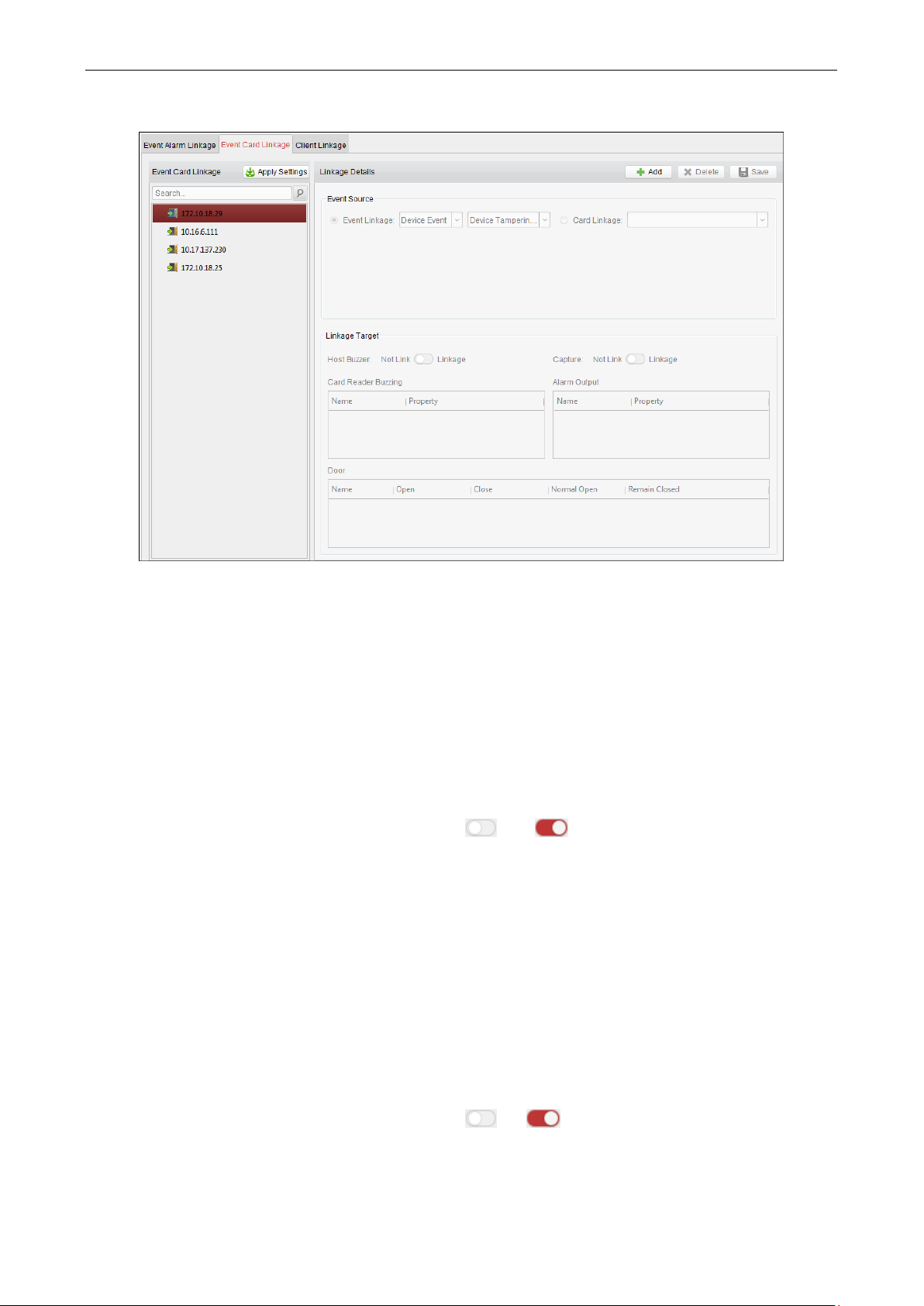
Video Access Control Terminal User Manual
67
Select the access control device from the list on the left.
Click Add button to add a new linkage. You can select the event source as Event Linkage or Card Linkage.
Event Linkage
For the event linkage, the alarm event can be divided into four types: device event, alarm input, door event, and
card reader event.
Steps:
1. Click to select the linkage type as Event Linkage, and select the event type from the dropdown list.
For Device Event, select the detailed event type from the dropdown list.
For Alarm Input, select the type as alarm or alarm recovery and select the alarm input name from the
table.
For Door Event, select the detailed event type and select the door from the table.
For Card Reader Event, select the detailed event type and select the card reader from the table.
2. Set the linkage target, and switch the property from to to enable this function.
Host Buzzer: The audible warning of controller will be triggered.
Capture: The real-time capture will be triggered.
Reader Buzzer: The audible warning of card reader will be triggered.
Alarm Output: The alarm output will be triggered for notification.
Door: The door status of open, close, remain open, and remain close will be triggered.
Note: The door status of open, close, remain open, and remain close cannot be triggered at the same time.
3. Click Save button to save parameters.
4. Click Apply Settings to apply the updated parameters to the local memory of the device to take effect.
Card Linkage
Steps:
1. Click to select the linkage type as Card Linkage.
2. Input the card No. or select the card from the dropdown list.
3. Select the card reader from the table for triggering.
4. Set the linkage target, and switch the property from to to enable this function.
Host Buzzer: The audible warning of controller will be triggered.
Page 73

Video Access Control Terminal User Manual
68
Capture: The real-time capture will be triggered.
Reader Buzzer: The audible warning of card reader will be triggered.
Alarm Output: The alarm output will be triggered for notification.
5. Click Save button to save parameters.
6. Click Apply Settings to apply the updated parameters to the local memory of the device to take effect.
MAC Linkage
You can link the device by setting the MAC address.
1. Select a device in the event card linkage list.
2. Click Add in the Linkage Details page.
3. Select MAC Linkage in the Event Source part. And input the MAC address in the text box.
4. Set the linkage target parameters, including the host buzzer the capture, the record, the card reader buzzing,
the alarm out, and the door.
5. Click Save to save the settings.
6. Click Apply Settings to apply the updated parameters to the local memory of the device to take effect.
Client Linkage
Purpose:
You can assign other access control device linkage actions to the trigger by setting up a rule in client linkage.
In the Linkage Configuration interface, click Client Linkage tab to enter the following interface.
Page 74
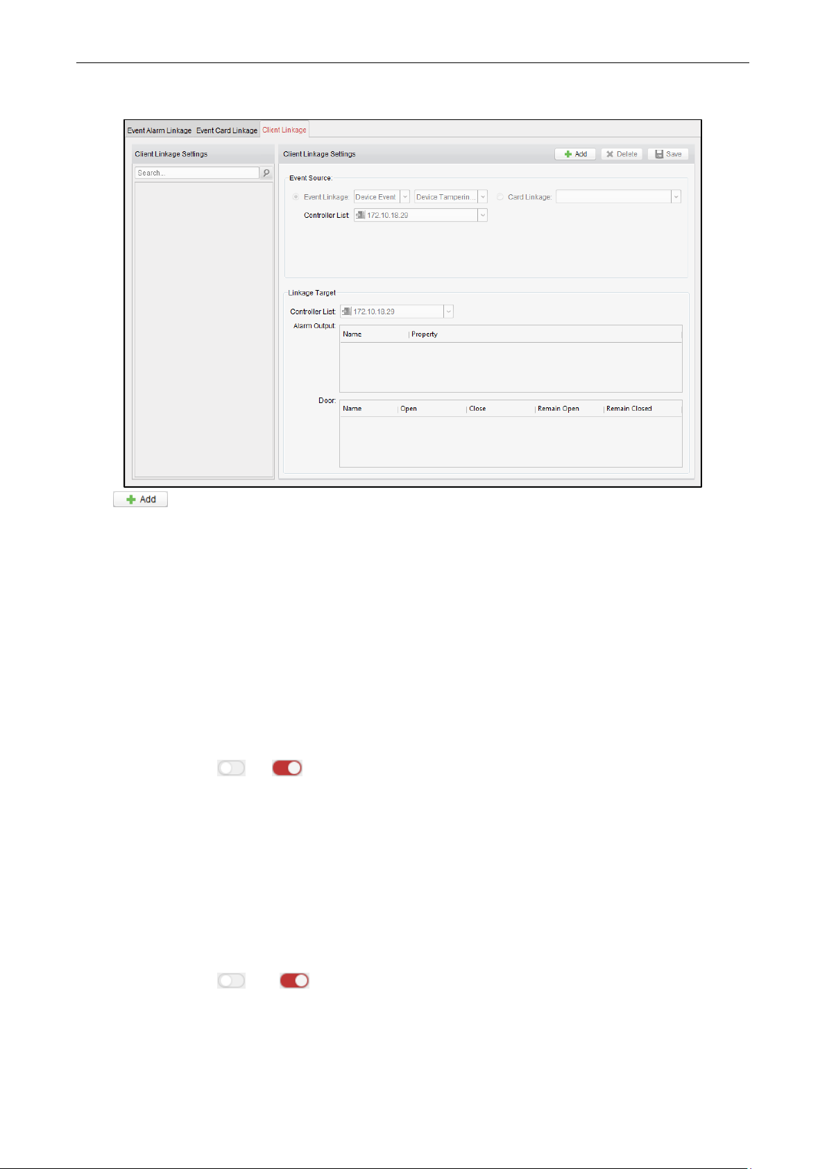
Video Access Control Terminal User Manual
69
Click button to add a new client linkage. You can select the event source as Event Linkage or Card
Linkage.
Event Linkage
For the event linkage, the alarm event can be divided into four types: device event, alarm input, door event, and
card reader event.
Steps:
1. Click to select the linkage type as Event Linkage, select the access control device as event source, and select
the event type from the dropdown list.
For Device Event, select the detailed event type from the dropdown list.
For Alarm Input, select the type as alarm or alarm recovery and select the alarm input name from the
table.
For Door Event, select the detailed event type and select the door from the table.
For Card Reader Event, select the detailed event type and select the card reader from the table.
2. Set the linkage target, select the access control device from the dropdown list as the linkage target, and switch
the property from to to enable this function.
Alarm Output: The alarm output will be triggered for notification.
Door: The door status of open, close, remain open, and remain close will be triggered. Note: The door
status of open, close, remain open, and remain close cannot be triggered at the same time.
3. Click Save button to save parameters.
Card Linkage
Steps:
1. Click to select the linkage type as Card Linkage.
2. Select the card from the dropdown list and select the access control device as event source.
3. Select the card reader from the table for triggering.
4. Set the linkage target, select the access control device from the dropdown list as the linkage target, and switch
the property from to to enable this function.
Alarm Output: The alarm output will be triggered for notification.
5. Click Save button to save parameters.
Page 75

Video Access Control Terminal User Manual
70
7.3.6 Permission Configuration
Click icon on the control panel to enter the Access Control Permission interface.
In Permission Configuration module, you can add, edit, and delete the access control permission, and then apply
the permission settings to the device to take effect.
Adding Permission
Purpose:
You can assign permission for people/department to enter/exist the control points (doors) in this section.
Steps:
1. Click Add icon on the upper-left side of the page to enter following interface.
Page 76

Video Access Control Terminal User Manual
71
2. Select the permission type.
By Person: You can select people from the list to enter/exit the door.
By Department: You can select departments from the list to enter/exit the door. Once the permission is
allocated, all the people in this department will have the permission to access the door.
By Access Control Point: You can select doors from the door list for people to enter/exit.
By Door Group: You can select groups from the door list for people to enter/exit. The permission will take
effect on the door in this group.
Note: The Door Group Permission will be available after the door group is added. For details about the
door group, refer to 3.2 Door Group Management.
3. Click Next to enter the Permission Settings interface.
4. Click on the dropdown menu to select a schedule template for the permission.
Note: The schedule template must be configured before any permission settings. You can click Add Template
button to add the schedule template. Refer to 4.3 Schedule Template for details.
5. Select people/department and corresponding doors/door groups from the appropriate lists.
6. Click Finish button to complete the permission adding.
7. (Optional) You can double click Template column of the added permission in the list to edit its permission
Page 77

Video Access Control Terminal User Manual
72
schedule template.
You can select the added permission in the list and click Delete to delete it.
Applying Permission
You can apply the added permission to the access control to take effect.
Steps:
1. Click Apply to enter the Apply Permission interface as follows.
2. Select the Applying Method.
Apply All: Apply all the permission settings in the list to the selected access control device.
Apply Changes: Apply the changed permissions to the selected access control device.
3. Select an access control device and click OK button to start applying the permission to the device.
Importing/Exporting Permission
You can also export the added permissions information to the local PC and import the permissions in batch from
the local PC.
Steps:
1. To import the permission in batch, click Import button to pop up the following dialog box.
Page 78
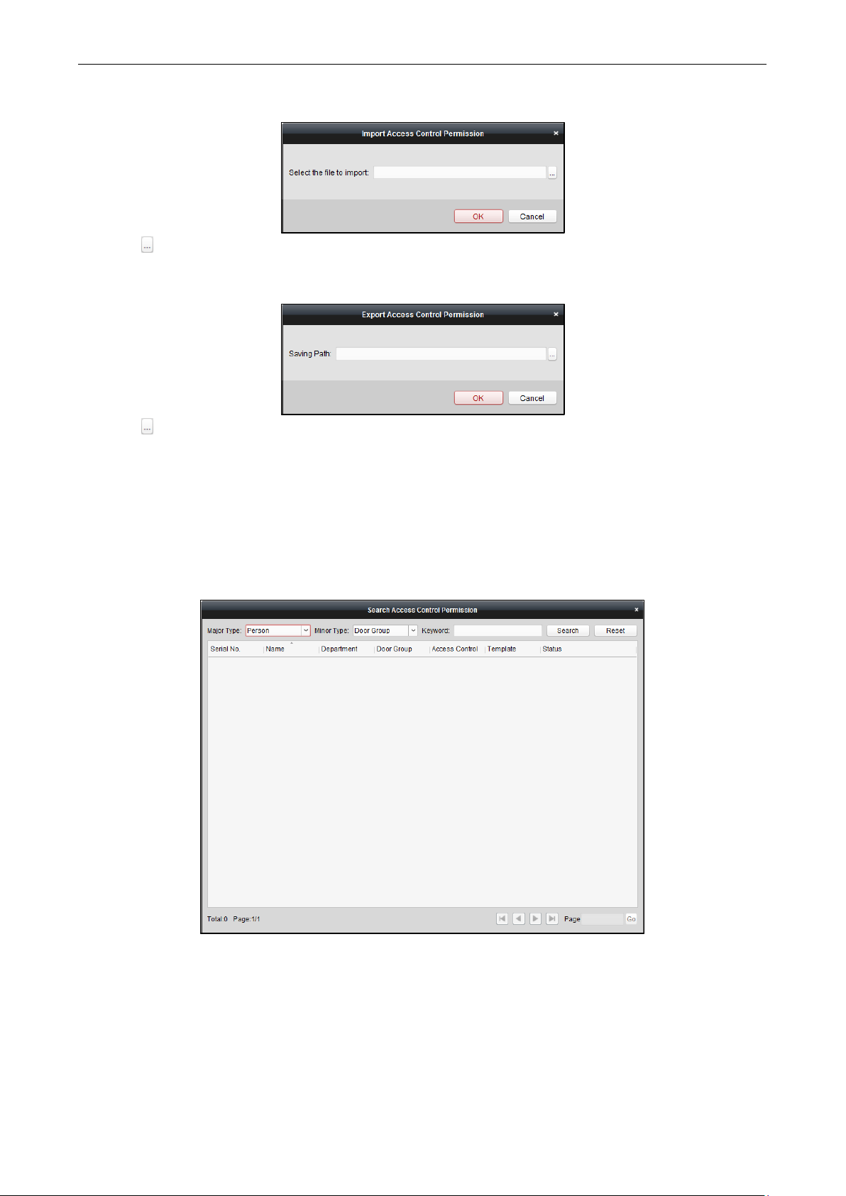
Video Access Control Terminal User Manual
73
Click to select the package file containing the permission information.
Click OK to start importing.
2. To export the permissions to the local PC, click Export button to pop up the following dialog box.
Click , input the permission file name as desired and select the saving path of the exported package file
containing the permission information.
Click OK to start exporting.
Note: The exported permission file is not editable.
Searching Access Control Permission
You can search the added access control permission via the client.
Steps:
1. Click Tool->Search Access Control Permission on the menu to enter the following interface.
2. Set the major type as the main search condition from the dropdown list. You can set it as by person,
department, door group, or access control point.
3. Set the minor type as the second search condition from the dropdown list. You can set it as by door group or
access control point.
4. You can also input the keyword of the permission.
5. Click Search to start searching the result.
You can click Reset the set the search condition to the default value.
Page 79
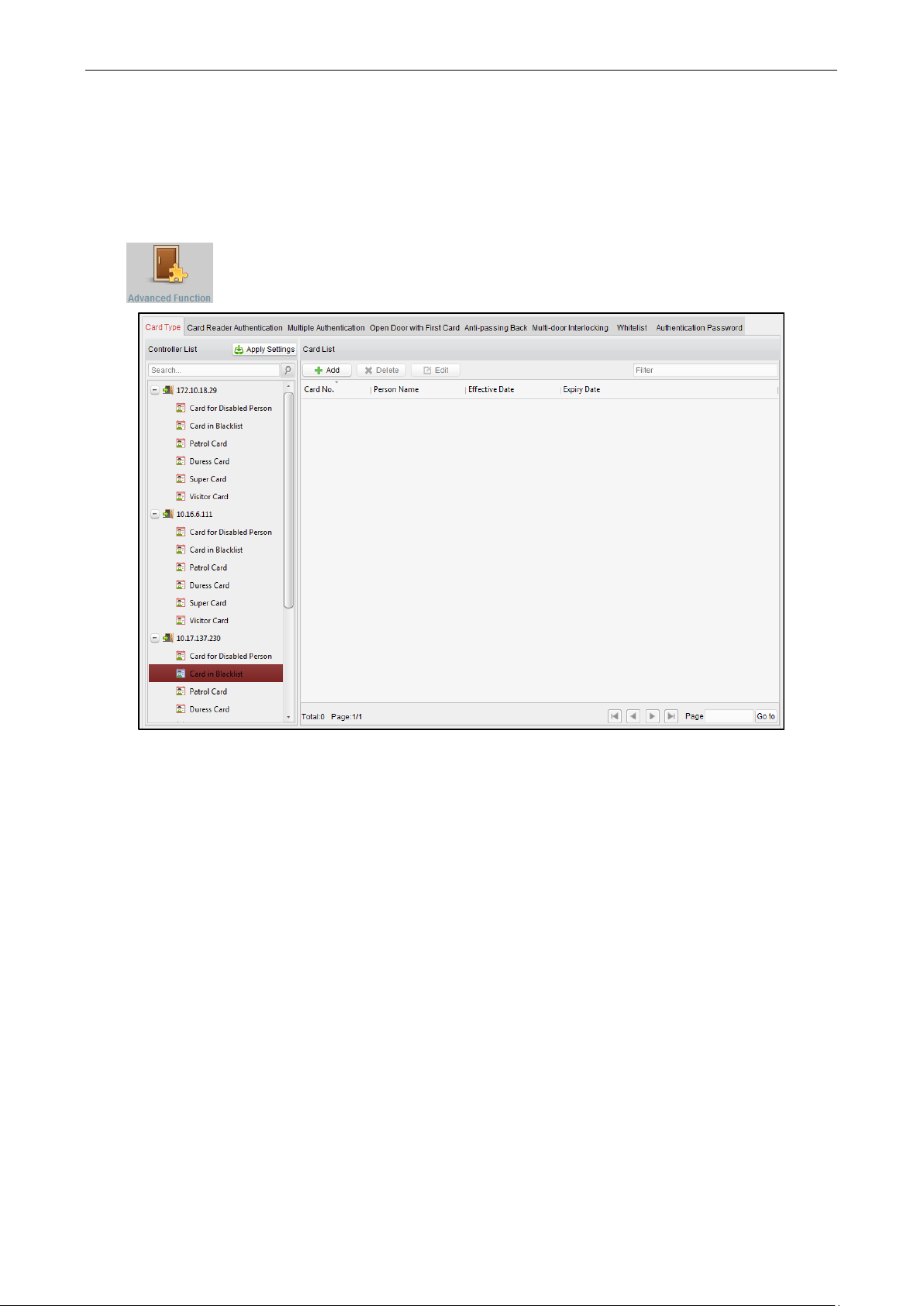
Video Access Control Terminal User Manual
74
7.3.7 Advanced Functions
Purpose:
After configuring the person, card, template, status duration, alarm linkage, and access permission, the advanced
functions of the Access Control Client can be configured, such as access control type, authentication password
and first card.
Click icon on the control panel to enter the following interface.
Card Type
Purpose:
The added cards can be assigned with different card type for the corresponding usage.
Note: Please set the card permission and apply the permission setting to the access control device first. For
details, refer to 4.6 Permission Configuration.
Steps:
1. Click Card Type tab and select a card type.
Page 80
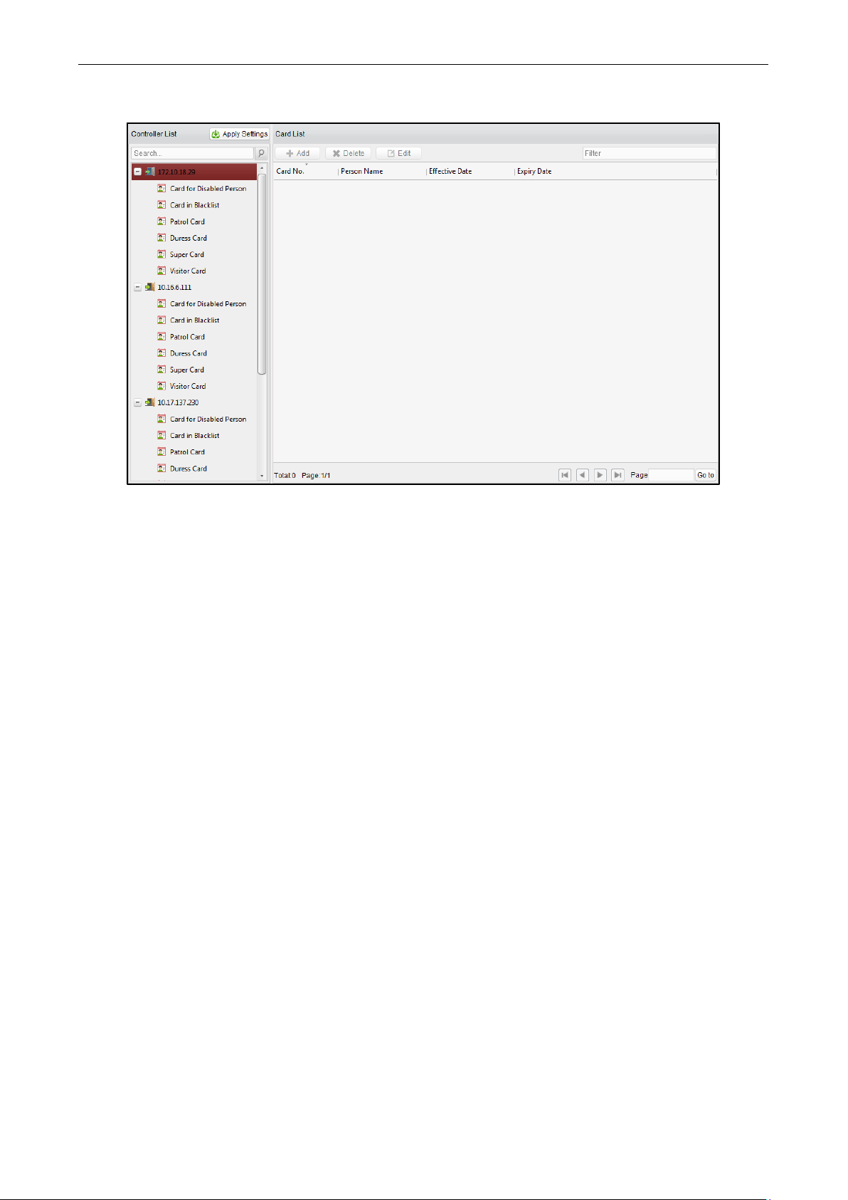
Video Access Control Terminal User Manual
75
Card for Door Extended Opening: The door will remain open for the configured time period for the card
holder.
Card in Blocklist: The card swiping action will be uploaded and the door cannot be opened.
Patrol Card: The card swiping action can used for checking the working status of the inspection staff. The
access permission of the inspection staff is configurable.
Duress Card: The door can open by swiping the duress card when there is duress. At the same time, the
client can report the duress event.
Super Card: The card is valid for all the doors of the controller during the configured schedule.
Visitor Card: The card is assigned for visitors.
Dismiss Card: The card can be swiped to stop the buzzer of the card reader.
Notes:
The available card types depend on the access control device type.
If the card is not assigned as any of the above card types, it is assigned as normal card by default.
2. Click Add and select the available card.
Page 81

Video Access Control Terminal User Manual
76
3. Click OK to confirm assigning the card(s) to the selected card type.
4. For the Visitor Card, you can click the added card and click Edit to edit the Max. Swipe Times, card Effective
Time and Expiry Time.
Note: The Max. Swipe Times should be between 0 and 255. When setting as 0, it means the card swiping is
unlimited.
5. Click Apply Settings button to take effect of the new settings.
6. (Optional) You can click Delete to remove the card from the card type and the card can be available for
being re-assigned.
Card Reader Authentication
You can set the passing rules for the card reader.
Steps:
1. Click Card Reader Authentication tab and select a card reader on the left.
2. Select a card reader authentication mode. The available authentication modes depend on the card reader
type:
Card and Password: The door can open by both inputting the card password and swiping the card.
Note: Here the password refers to the password set when issuing the card. Refer to 4.2.1 Empty Card.
Card or Authentication Password: The door can open by inputting the authentication password or
swiping the card.
Note: Here the authentication password refers to the password set to open the door. Refer to
4.7.8 Multi-door Interlocking
Page 82

Video Access Control Terminal User Manual
77
You can set the multi-door interlocking between multiple doors of the same access control device. To open one
of the doors, other doors must keep closed. That means in the interlocking combined door group, up to one door
can be opened at the same time.
Notes:
The Multi-door Interlocking function is only supported by the access control device which has more than
one access control points (doors).
Either the anti-passing back or multi-door interlocking function can be configured for an access control
device at the same time.
Steps:
1. Click Multi-door Interlocking tab and select an access control point from the list.
2. Click Add to pop up the Add Access Control Point to Interlock interface.
3. Select the access control point (door) from the list.
Note: Up to four doors can be added in one multi-door interlocking combination.
4. Click OK to save the adding.
5. (Optional) After adding the multi-door interlocking combination, you can select it from the list and click
Delete to delete the combination.
Click Apply Settings button to take effect of the new settings.
White List
You can add the mobile phone number to the access control device for access permissions. The mobile phone
can control the door and the zones by sending SMS control instructions.
Steps:
1. Click the White List tab to enter the white list interface.
Page 83
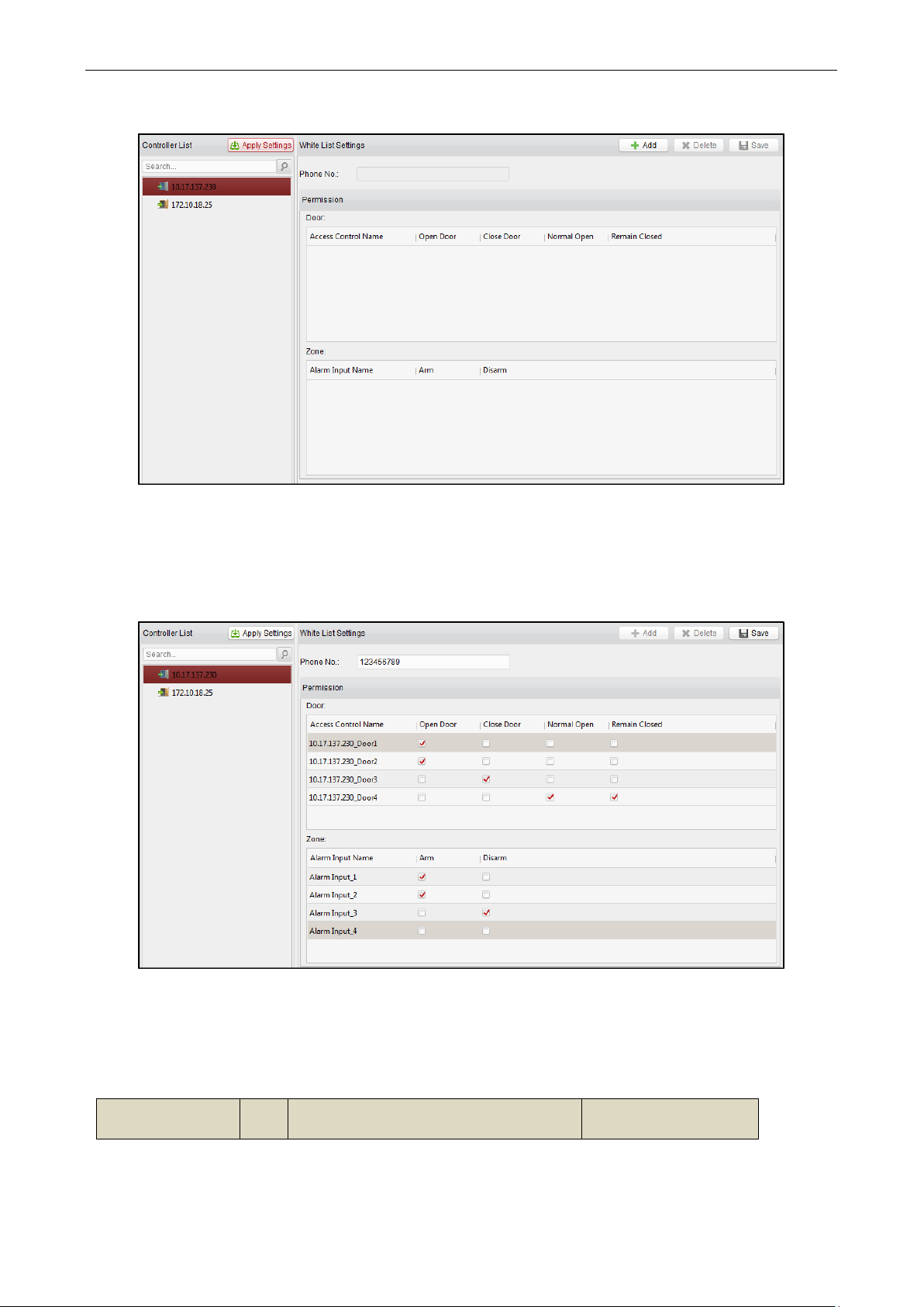
Video Access Control Terminal User Manual
78
2. Select the access control device from the list and click Add button.
3. Input the mobile number.
4. Select the access control permission. You can check the corresponding checkbox to enable the permission.
Door: The mobile can control the door (open, closed, remain open, or remain closed).
Zone: The mobile can arm and disarm the zone.
5. Click Save button to save parameters.
6. You can select the added white list and click Delete button to delete it.
7. Click Apply Settings button to take effect of the new settings.
Notes:
Up to 8 white lists can be added for one access control device.
The mobile can control the door and the zones by sending SMS control instructions. The SMS control
instruction is composed of Command, Operation Range, and Operation Object.
Instruction
Content
Digit
Description
Format
Page 84

Video Access Control Terminal User Manual
79
Command
3
010-Open, 011-Closed, 020-Remain open,
021-Remain Closed, 120-Disarm, 121-Arm
Operation Range
1
1-all objects with permission, 2-single
operation
Command#1#
Operation Object
3
Starts from 1 (corresponding to different
doors or arming regions according to
commands)
Command#2#Operation
Object#
Authentication Password.
Fingerprint: The door can open by only inputting the fingerprint.
Card: The door can open by only swiping the card.
Card or Fingerprint: The door can open by inputting the fingerprint or swiping the card.
Password and Fingerprint: The door can open by both inputting the card password and inputting the
fingerprint.
Note: Here the password refers to the password set when issuing the card. Refer to 4.2.1 Empty Card.
Card and Fingerprint: The door can open by both inputting the fingerprint and swiping the card.
Card, Password and Fingerprint: The door can open by both inputting the fingerprint, inputting the
card password, and swiping the card.
Note: Here the password refers to the password set when issuing the card. Refer to 4.2.1 Empty Card.
3. Click and drag your mouse on a day to draw a color bar on the schedule, which means in that period of time,
the card reader authentication is valid.
4. Repeat the above step to set other time periods.
Or you can select a configured day and click Copy to Week button to copy the same settings to the whole
week.
You can click Delete button to delete the selected time period or click Clear button to delete all the
configured time periods.
5. (Optional) Click Copy to button to copy the settings to other card readers.
Page 85

Video Access Control Terminal User Manual
80
6. Click Save button to save parameters.
7. Click Apply Settings button to take effect of the new settings.
Multiple Authentication
You can manage the cards by group and set the authentication for multiple cards for one access control point
(door).
Note: Please set the card permission and apply the permission setting to the access controller first. For details,
refer to 4.6 Permission Configuration.
Steps:
1. Click Multiple Authentication tab and select an access control point (door) from the list on the left.
2. Click Add Authentication Group button to pop up the following interface:
3. Click the card group from the list, and Add to select the card to add the card group.
Note: Please set the card permission and apply the permission setting to the access control device first. For
details, refer to 4.6 Permission Configuration.
You can click of the card group to edit the group name.
4. Input the Card Swiping Times for the selected card group.
Page 86
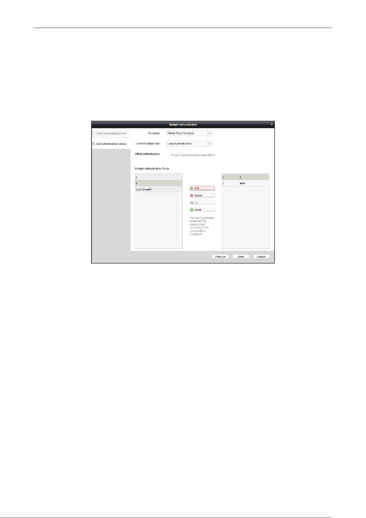
Video Access Control Terminal User Manual
81
Notes:
The Card Swiping Times should be larger than 0 and smaller than the added card number in the card
group.
The upper limit of Card Swiping Times is 16.
5. Select the effective time and expiry time for the selected card group.
Note: You can also click Card Group Management button on the Multiple Authentication tab page to set the
card group.
6. Click Next to enter the Add Authentication Group interface.
7. Select the template of the authentication group from the dropdown list. For details about setting the
template, refer to 4.3 Schedule Template.
8. Select the authentication type of the authentication group from the dropdown list.
Local Authentication: Authentication by the access control device.
Local Authentication and Remotely Open Door: Authentication by the access control device and by the
client.
For Local Authentication and Remotely Open Door type, you can check the checkbox to enable the
super password authentication when the access control device is disconnected with the client.
Local Authentication and Super Password: Authentication by the access control device and by the
super password.
9. In the list on the left, the card group name will be displayed. You can click the card group and click Add to
add the group to the authentication group.
You can click the added card group and click Delete to remove it from the authentication group.
You can also click Up or Down to set the card swiping order.
10. Click Done to save the settings.
11. Click Apply Settings button to take effect of the new settings.
Notes:
For each access control point (door), up to four authentication groups can be added.
For the authentication group which certificate type is Local Authentication, up to 8 card groups can be
added to the authentication group.
For the authentication group which certificate type is Local Authentication and Super Password or Local
Authentication and Remotely Open Door, up to 7 card groups can be added to the authentication group.
Page 87

Video Access Control Terminal User Manual
82
Open Door with First Card
Purpose:
The door remains open for the configured time duration after the first card swiping until the remain open
duration ends.
Steps:
1. Click Open Door with First Card tab and select an access control device from the list on the left.
2. Check the checkbox of Enable First Card Remain Open to enable this function.
3. In the Remain Open Duration (min), input the time duration for remaining open the door.
Note: The Remain Open Duration should be between 0 and 1440 minutes. By default, it is 10 minutes.
4. In the First Card list, Click Add button to pop up the following dialog box.
1) Select the cards to add as first card for the door and click OK button.
Page 88

Video Access Control Terminal User Manual
83
Note: Please set the card permission and apply the permission setting to the access control device first.
For details, refer to 4.6 Permission Configuration.
2) You can click Delete button to remove the card from the first card list.
5. Click Save and then click Apply Settings button to take effect of the new settings.
Anti-Passing Back
Purpose:
You can set to only pass the access control point according to the specified path and only one person could pass
the access control point after swiping the card.
Notes:
Either the anti-passing back or multi-door interlocking function can be configured for an access control
device at the same time.
You should enable the anti-passing back function on the access control device first.
Setting the Path of Swiping Card (Card Reader Order)
Steps:
1. Click Anti-passing Back tab and select an access control point.
2. You can select the card reader as the beginning of the path.
3. In the list, click the text filed of Card Reader Afterward and select the linked card readers.
Example: If you select Reader In_01 as the beginning, and select Reader In_02, Reader Out_04 as the linked
card readers. Then you can only get through the access control point by swiping the card in the order as
Reader In_01, Reader In_02 and Reader Out_04.
Note: Up to four afterward card readers can be added for one card reader.
4. Check the Enable Anti-Passing Back checkbox to enable the anti-passing back function of the card reader.
5. (Optional) You can enter the Select Card Reader dialog box again to edit its afterward card readers.
6. Click Save and then click Apply Settings button to take effect of the new settings.
Page 89
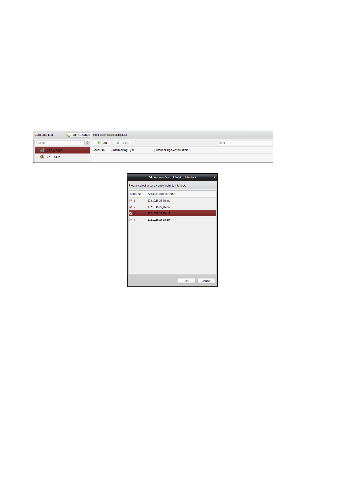
Video Access Control Terminal User Manual
84
Multi-door Interlocking
You can set the multi-door interlocking between multiple doors of the same access control device. To open one
of the doors, other doors must keep closed. That means in the interlocking combined door group, up to one door
can be opened at the same time.
Notes:
The Multi-door Interlocking function is only supported by the access control device which has more than
one access control points (doors).
Either the anti-passing back or multi-door interlocking function can be configured for an access control
device at the same time.
Steps:
6. Click Multi-door Interlocking tab and select an access control point from the list.
7. Click Add to pop up the Add Access Control Point to Interlock interface.
8. Select the access control point (door) from the list.
Note: Up to four doors can be added in one multi-door interlocking combination.
9. Click OK to save the adding.
10. (Optional) After adding the multi-door interlocking combination, you can select it from the list and click
Delete to delete the combination.
Click Apply Settings button to take effect of the new settings.
White List
You can add the mobile phone number to the access control device for access permissions. The mobile phone
can control the door and the zones by sending SMS control instructions.
Steps:
8. Click the White List tab to enter the white list interface.
Page 90

Video Access Control Terminal User Manual
85
9. Select the access control device from the list and click Add button.
10. Input the mobile number.
11. Select the access control permission. You can check the corresponding checkbox to enable the permission.
Door: The mobile can control the door (open, closed, remain open, or remain closed).
Zone: The mobile can arm and disarm the zone.
12. Click Save button to save parameters.
13. You can select the added white list and click Delete button to delete it.
14. Click Apply Settings button to take effect of the new settings.
Notes:
Up to 8 white lists can be added for one access control device.
The mobile can control the door and the zones by sending SMS control instructions. The SMS control
instruction is composed of Command, Operation Range, and Operation Object.
Instruction
Content
Digit
Description
Format
Page 91
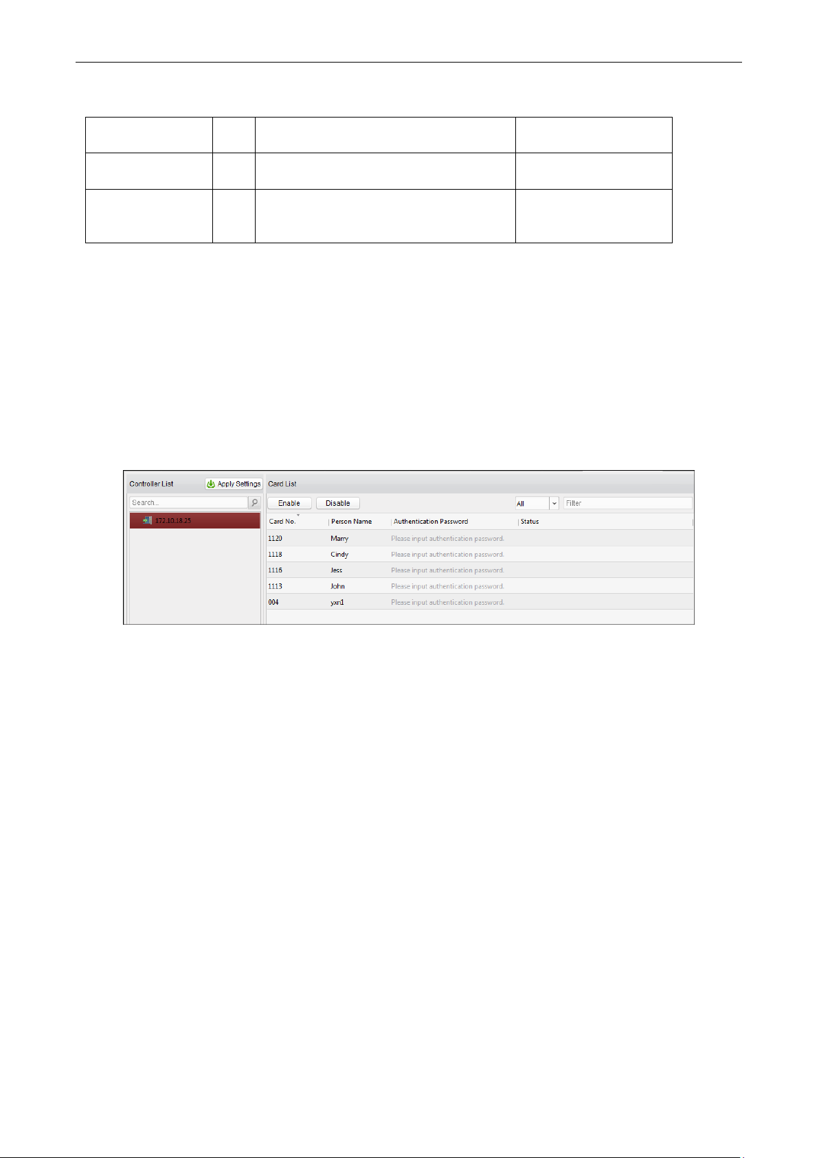
Video Access Control Terminal User Manual
86
Command
3
010-Open, 011-Closed, 020-Remain open,
021-Remain Closed, 120-Disarm, 121-Arm
Operation Range
1
1-all objects with permission, 2-single
operation
Command#1#
Operation Object
3
Starts from 1 (corresponding to different
doors or arming regions according to
commands)
Command#2#Operation
Object#
Authentication Password
Purpose:
You can open the door by inputting the authentication password on the card reader keypad after finishing the
operation of setting authentication password.
Notes:
This authentication password function is only valid during the schedules when the card reader
authentication mode for the access control device is set as Card or Authentication Password. For details,
please refer to 4.7.2 Card Reader Authentication.
This function should be supported by the access control device.
Steps:
1. Click Authentication Password tab and select an access control device from the list.
All the cards and persons which have been applied to the device will be displayed.
2. Click the Authentication Password field of the card and input the authentication password for the card.
Note: The authentication password should contain 4 to 8 digits.
3. After setting the authentication password, the authentication password function of the card will be enabled
by default.
You can click Disable to disable the card’s authentication password.
You can also click Enable to enable it again.
4. (Optional) You can input the keywords of card No., person name, or authentication password to search.
You can also set the condition to filter the cards which have enabled the authentication password function
and the cards which haven’t.
Note: Up to 500 cards with authentication password can be added to one access control device. The password
should be unique and cannot be same with each other.
Page 92
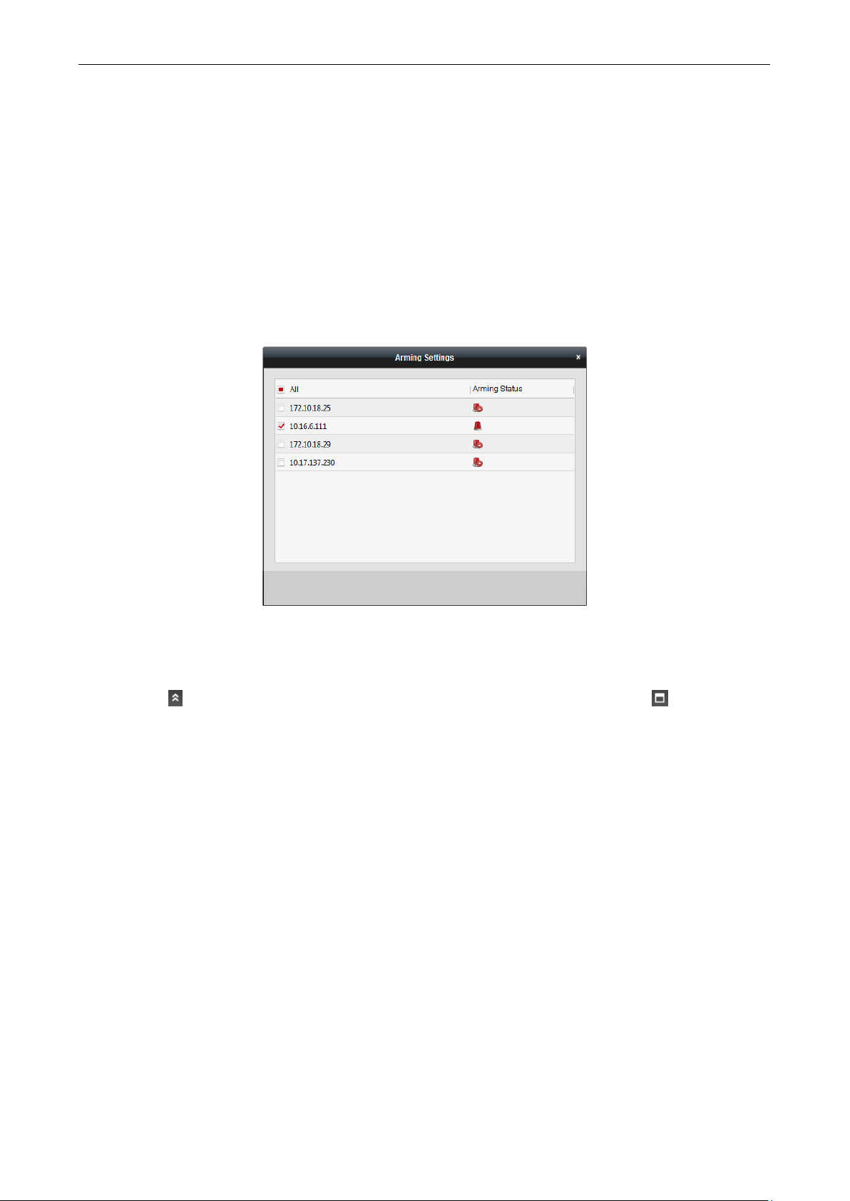
Video Access Control Terminal User Manual
87
7.4 Event and Alarm Management
Purpose:
In this section, you are able to check the real-time events and alarms, and view the event report of the access
control point.
7.4.1 Real-Time Access Control Event and Alarm
Purpose:
You can view the real-time alarm and event information received by the client.
Before you start:
Before you can receive the alarm information from the device, you need to click Tool -> Arming Settings and arm
the device by checking the corresponding checkbox.
Note: The device will be armed by default after being added to the client.
After enabling the arming control of the access control device, the client can receive the alarms and events once
triggered.
Click the icon in Alarms and Events Toolbar to show the Alarms and Events panel. Or click to display the
Alarm Event interface.
Page 93
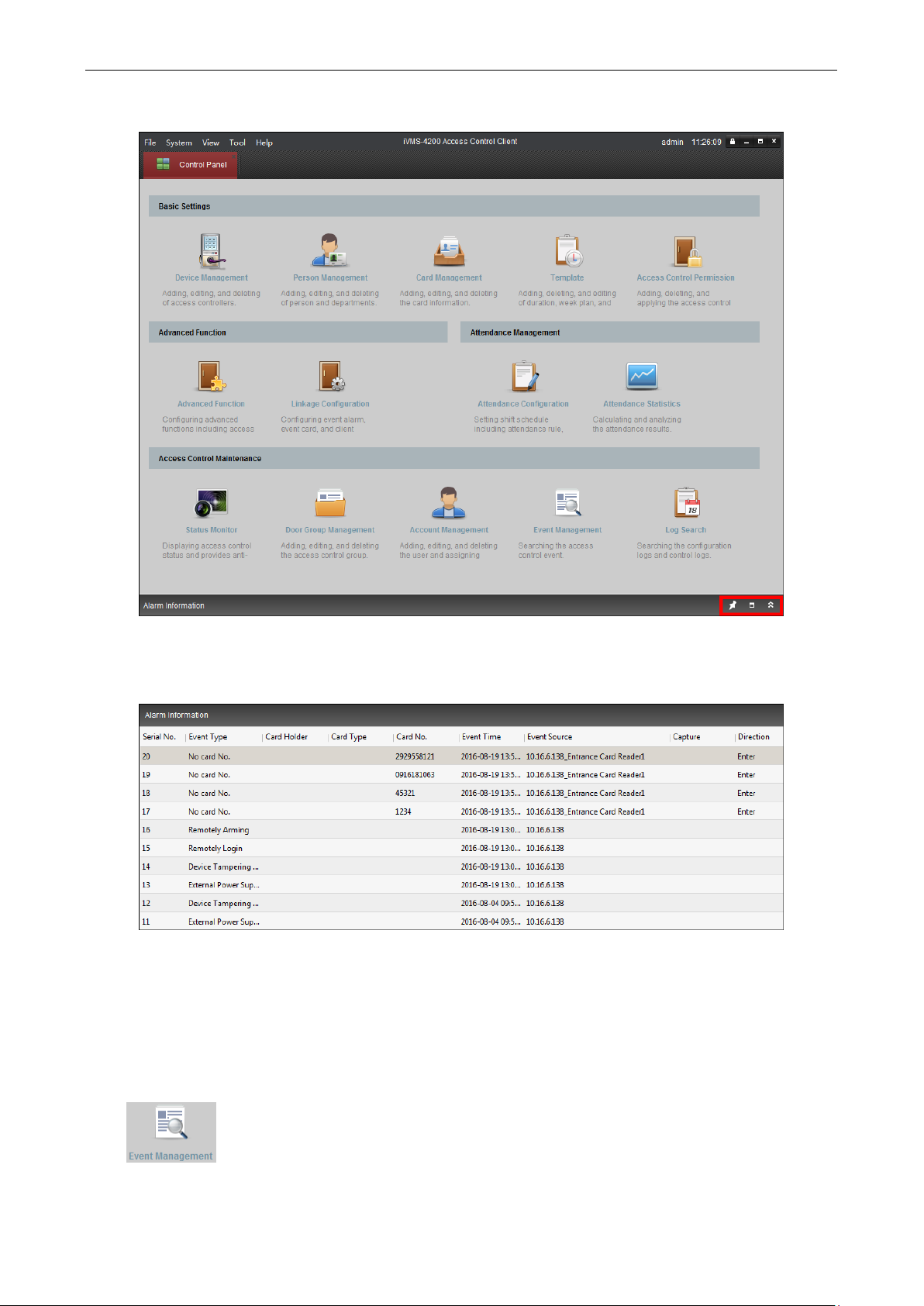
Video Access Control Terminal User Manual
88
You can view real-time access event (such as swiping to open the door, unrecognized card number, duration
group error, etc.) information and other operation events in Alarm Event interface.
Note: If you cannot receive the event and alarm information of the access control device, you can check the
arming status of the device in Tool -> Arming Settings.
You can click the card swiping event to view the card holder information.
You can click to view the captured alarm pictures if the storage server is configured. For configuring the storage
server, please refer to 8.4.4 Storage Server Configuration.
7.4.2 Event Management
Purpose:
You can search historical access event according to the search conditions (such as event type, name of the
person, card No. or start/end time).
Click icon on the control panel to enter the interface.
Page 94

Video Access Control Terminal User Manual
89
Steps:
1. Select the source.
You can select Client or Device.
2. Enter the search condition (source, event type/card holder name/card No./capture/start & end time).
3. Click Search to get the search results.
4. View the event information in the event list.
5. Click an event to view the information of the card holder on the Card Holder Information panel on the left
side of the page.
6. You can click Export button to export the search results to the local PC.
Page 95

Video Access Control Terminal User Manual
90
7.5 System Maintenance
7.5.1 Log Management
Purpose:
The log files of the Access Control Client and the devices that connected to the Access Control Client can be
searched for checking.
Click icon on the control panel to open the Log Search page.
Searching Configuration Logs
Purpose:
The operation logs via the Access Control Client can be searched by time.
Steps:
1. Open the Log Search page.
2. Select the radio button of Configuration Logs.
3. Select the Operation Type of log files. For cofiguration log, the operation type includes department
management, card managemene, access control permission configuration, ect..
4. Click to specify the start time and end time.
5. Click Search. The matched log files will display on the right.
You can check the operation time, log type and other information of the logs.
6. You can click Export to export the search result to the local PC.
Note: Please narrow the search condition if there are too many log files.
Searching Control Logs
Purpose:
The logs of controlling access control point via the client can be searched by time.
Steps:
1. Open the Log Search page.
Page 96
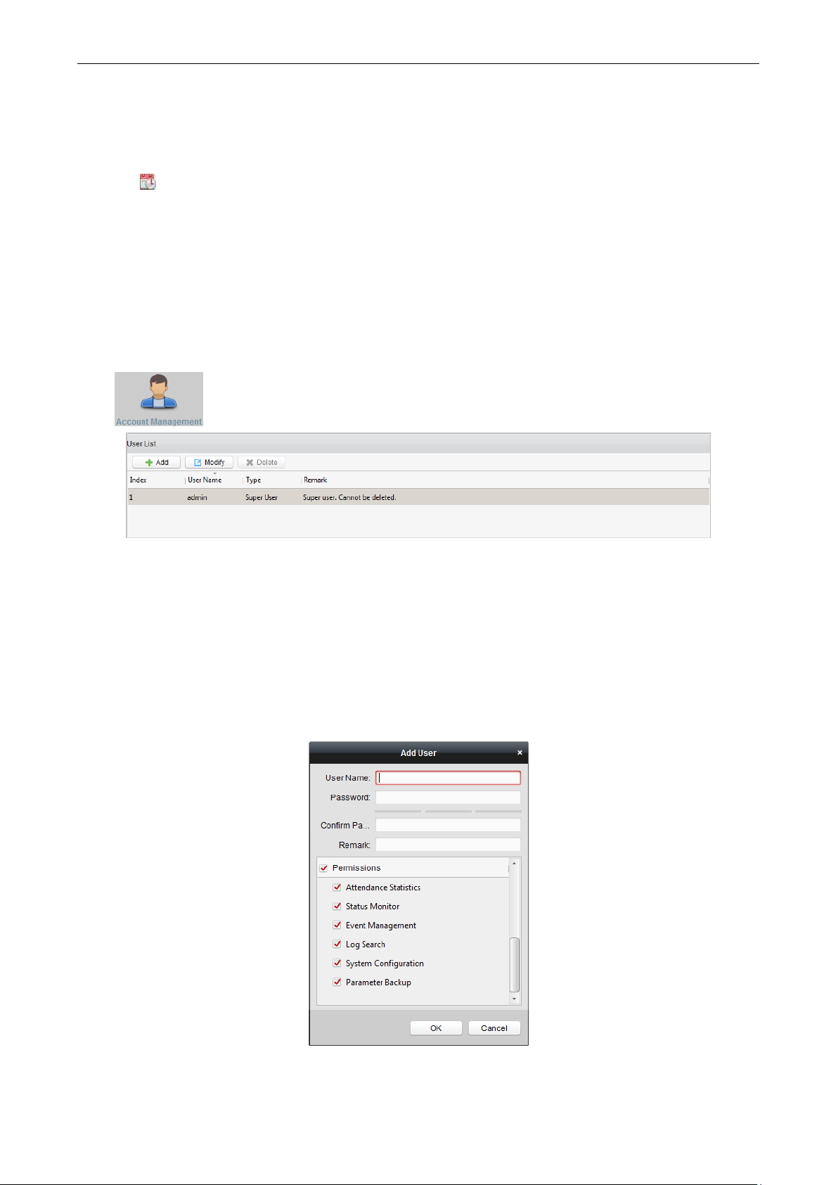
Video Access Control Terminal User Manual
91
2. Select the radio button of Control Logs.
3. Select the Operation Type of log files. For control log, the operation type includes opening door, closing door,
remaining open, remaining closed, and capture.
4. Click to specify the start time and end time.
5. Click Search. The matched log files will display on the right.
You can check the operation time, log type and other information of the logs.
6. You can click Export to export the search result to the local PC.
Note: Please narrow the search condition if there are too many log files.
7.5.2 Account Management
Purpose:
Multiple user accounts can be added to the client software, and you are allowed to assign different permissions
for different users if needed.
Click icon on the control panel to open the Account Management page.
Note: The user account you registered to log in to the software is set as the super user.
Adding the User
Steps:
1. Open the Account Management page.
2. Click Add to open the Add User dialog box.
3. Input the user name, password and confirm password as desired. The software will judge password strength
automatically, and we highly recommend you to use a strong password to ensure your data security.
4. Check the checkboxes to assign the permissions for the created user.
5. Click OK to save the settings.
Note: Up to 16 user accounts can be added to the client.
Page 97

Video Access Control Terminal User Manual
92
A user name cannot contain any of the following characters: / \ : * ? “ < > |. And the length of the
password cannot be less than 8 characters.
For your privacy, we strongly recommend changing the password to something of your own choosing
(using a minimum of 8 characters, including upper case letters, lower case letters, numbers, and special
characters) in order to increase the security of your product.
Proper configuration of all passwords and other security settings is the responsibility of the installer
and/or end-user.
Managing the User
Purpose:
After created successfully, the user account is added to the user list on the Account Management page. You can
edit or delete the information of the user accounts.
To edit the information of the user, select the user from the list, and click Modify.
To delete the information of the user, select the user from the list, and click Delete.
Note: The super user cannot be deleted and its permission cannot be modified.
7.5.3 Auto Backup Settings
Purpose:
You can set to enable the auto backup function to back up the client database automatically such as person,
attendance data, permission data, etc.
Steps:
1. Click System -> Auto Backup to open the Auto Backup window as follows.
2. Check the Enable checkbox to enable the Auto Backup function.
3. Click to set the path for saving the backed file.
4. Set the date and time for backing up the database.
5. Click OK to save the settings.
7.5.4 System Configuration
Purpose:
The general parameters, card reader, fingerprint machine, and storage server can be configured.
General Settings
Steps:
1. Click Tool->System Configuration to open the System Configuration page.
Page 98
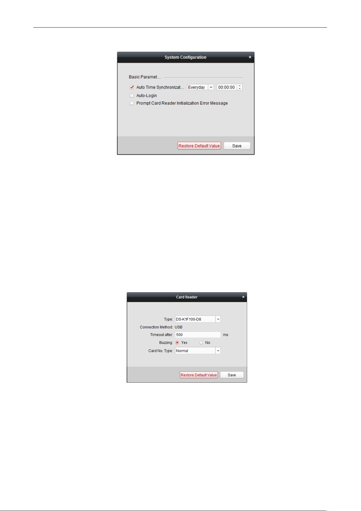
Video Access Control Terminal User Manual
93
2. Check the checkbox to enable Automatic Time Synchronization.
The Automatic Time Synchronization can operate auto time adjustment to all access control devices added
to the Access Control Client according to specified period and time.
Select the matched day and input the time to operate the time adjustment.
3. You can check the checkbox to enable auto-login.
4. You can click the checkbox to enable the message prompt when the card reader initialization is error.
5. Click Save button to save the settings.
Note: You can click Restore Default Value button to restore the defaults of the general settings.
Card Reader Configuration
Purpose:
The Card Reader should connect with the PC running the client to read the card No..
You should configure the card reader before setting the card.
Note: Currently, the supported card reader types include DS-K1F100-D8, DS-K1F100-M, and DS-K1F100-D8E.
Steps:
1. Click Tool->Card Reader on the menu to pop up the card reader configuration dialog box.
2. Set the parameters about the connected card reader.
3. Click Save button to save the settings.
You can click Restore Default Value button to restore the defaults.
Fingerprint Machine Configuration
The fingerprint machine should connect with the PC running the client for collecting the fingerprint.
Steps:
1. Click Tool->Fingerprint Machine on the menu to open the Fingerprint Machine Configuration page.
Page 99
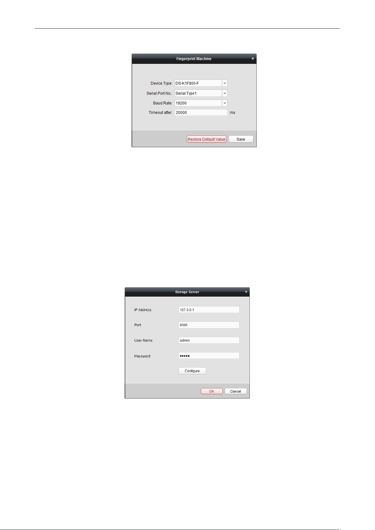
Video Access Control Terminal User Manual
94
2. Select the device type.
Currently, the supported fingerprint machine types include DS-K1F800-F, DS-K1F300-F, and DS-K1F810-F.
3. For fingerprint machine type DS-K1F800-F, you can set the serial port number, baud rate, and overtime
parameters of the fingerprint machine.
4. Click Save button to save the settings.
You can click Restore Default Value button to restore the default settings.
Notes:
The serial port number should correspond to the serial port number of PC.
The baud rate should be set according to the external fingerprint card reader. The default value is 19200.
Overtime refers to the valid fingerprint collecting time. If the user does not input a fingerprint or inputs a
fingerprint unsuccessfully, the device will indicate that the fingerprint collecting is over.
Storage Server Configuration
You should configure the storage server before capturing the pictures for the storage of captured pictures.
Steps:
1. Click Tool->Storage Server on the menu to enter the storage server configuration interface.
2. Input the storage server parameters including IP address, port No., user name, and password.
3. Click Configure button to enter the Remote Configuration interface as follows.
Page 100

Video Access Control Terminal User Manual
95
4. The HDDs of the storage server need to be formatted for the video file and picture storage.
1) Click Storage->General, to enter the HDD Formatting interface.
2) Select the HDD from the list and click Format. You can check the formatting process from the process
bar and the status of the formatted HDD changes from Unformatted to Normal Status.
Note: Formatting the HDDs is to pre-allocate the disk space for storage and the original data of the
formatted HDDs will not be deleted.
5. After formatting of the HDD, you can set the picture storage quota in the Remote Configuration interface.
 Loading...