

Page 1

4 Inch Speed Dome
Installation Manual
V2.0.0
2010-01
Page 2

4 Inch Speed Dome Installation Manual V2.0.0
1
Thank you for purchasing our product. If there is any question or request, please do not hesitate to contact dealer.
This manual is applicable to 4 Inch Speed Dome.
This manual may contain several technically incorrect places or printing errors, and the content is subject to change without notice.
The updates will be added into the new version of this manual. We will readily improve or update the products or procedures described
in the manual.
Page 3
4 Inch Speed Dome Installation Manual V2.0.0
2
Safety Instruction
These instructions are intended to ensure that user can use the product correctly to avoid danger or property loss. The precaution
measure is divided into “Warnings” and “Cautions”:
Warnings: Neglecting any of the warnings may cause serious injury or death.
Cautions: Neglecting any of the cautions may cause injury or equipment damage.
Warnings Follow these safeguards to prevent serious
injury or death.
Cautions Follow these precautions to
prevent potential injury or material
damage.
Warnings
1. In the use of the product, you must be strict compliance with the electrical safety regulations of the nation and region.
2. Please use the power adapter, which is provided by normal company. The standard of the power adapter is AC24V/3A or
DC12V/3.3A.
3. Do not connect several devices to one power adapter as adapter overload may cause over-heat or fire hazard.
4. Please make sure that the plug is firmly connected on the power socket.
5. When the product is installed on wall or ceiling, the device shall be firmly fixed.
6. If smoke, odors or noise rise from the device, turn off the power at once and unplug the power cable, and then please contact the
service center.
7. If the product does not work properly, please contact your dealer or the nearest service center. Never attempt to disassemble the
camera yourself. (We shall not assume any responsibility for problems caused by unauthorized repair or maintenance.)
Warnings
1. Do not drop the dome or subject it to physical shock, and do not expose it to high electromagnetism radiation. Avoid the equipment
installation on vibrations surface or places subject to shock (ignorance can cause equipment damage).
2. Do not place the dome in extremely hot, cold (the operating temperature shall be -10°C ~ +50°C), dusty or damp locations, or fire or
electrical shock will occur otherwise.
3. The dome cover for indoor use shall be kept from rain and moisture.
4. Exposing the equipment to direct sun light, low ventilation or heat source such as heater or radiator is forbidden (ignorance can
cause fire danger).
5. Do not aim the camera at the sun or extra bright places. A blooming or smear may occur otherwise (which is not a malfunction
however), and affecting the endurance of CCD at the same time.
6. Please use the provided glove when open up the dome cover, avoid direct contact with the dome cover, because the acidic sweat of
the fingers may erode the surface coating of the dome cover.
7. Please use a soft and dry cloth when clean inside and outside surfaces of the dome cover, not to use alkaline detergents.
Page 4

4 Inch Speed Dome Installation Manual V2.0.0
3
Preparation for Installation
1. Basic requirements
1) All the electronic operation should be strict compliance with the local electrical safety regulations, fire prevention
regulations and other related regulations at the installation place.
2) Check whether all the accessories are there according to the packing list, make sure that the place and installation mode are
conform to the demands, if not, please contact the supplier.
3) Please use this product according to the working environment.
2. Check installation space.
Make sure the place have enough space to install the speed domes and its accessories.
3. Check the intensity of conformation at the installation scene.
Please make sure that the endure ability of ceilings or walls is 4 times as the weight of speed dome and its accessories.
4. Preparation of cables
Choose the video cable according to the transmission length. The video should meet the least demands as:
1. 75Ω resistance
2. 100% copper core conducting wire.
3. 95% weaving copper shield.
RS485 communi
cation cable, please refer to Appendix 2
24V AC power cable, please refer to Appendix 3
5. Please keep all wrappers
Please keep all wrappers after unpack them for future use. In case of any failure occurred, please return the speed dome to the
factory with the original wrapper.
Note: Transportation without the original wrapper may result in damage on the speed dome and cost additional charge.
Page 5

4 Inch Speed Dome Installation Manual V2.0.0
4
Table of Contents
Table of Contents......................................................................................................................................................... 4
Chapter 1 Installation...................................................................................................................................................
5
1.1 .............................................................................................................................................
5 Check Parts List
1.2 .....................................................................................................................................................
5 Installation
1.3 ................................................................................................................................................
8 Initial Settings
1.4 .......................................................................................................................................
9 DIP Switch Settings
1.4.1 .......................................................................................................................... 9 Address Settings
1.4.2 ......................................................................................................................11 Baud Rate Settings
1.4.3 ........................................................................................11 Protocol Settings (High Speed Dome)
1.4.4 ..................................................11 Parity and Manchester Code Settings (Network Speed Dome)
1.4.5 .....................................................................................................11 Terminating Resistor Settings
1.5 ............................................................................................................................11 Alarm In/Out Connections
Chapter 2 Mounts Dimension....................................................................................................................................
13
2.1 Long-arm Wall Mount .................................................................................................................................
13
2.2 Short-arm Wall Mount.................................................................................................................................
14
2.3 Corner Adapter.............................................................................................................................................
14
2.4 Pole Adapter ................................................................................................................................................
15
2.5 Pendant Adapter...........................................................................................................................................
15
Chapter 3 Wall Mounting Applications ..................................................................................................................... 16
3.1 Mounting Components ................................................................................................................................
16
3.2 Wall Mounting Instructions ......................................................................................................................... 17
Chapter 4 Corner Mounting Applications.................................................................................................................. 19
4.1 Mounting Components ................................................................................................................................
19
4.2 Corner Mounting Instructions...................................................................................................................... 20
Chapter 5 Pole Mounting Applications...................................................................................................................... 22
5.1 Mounting Components ................................................................................................................................
22
5.2 .......................................................................................................................... 23 Pole Mounting Instructions
Chapter 6 Pendant Mounting Applications................................................................................................................ 26
6.1 Mounting Components ................................................................................................................................
26
6.2 Pendant Mounting Instructions .................................................................................................................... 27
Chapter 7 In-ceiling Mounting Applications ............................................................................................................. 29
7.1 Installation Conditions.................................................................................................................................
29
7.2 In-ceiling Mounting Instructions ................................................................................................................. 29
Appendix 1 RS485 Bus Connection.......................................................................................................................... 32
Appendix 2 24VAC Wire Gauge & Transmission Distance ...................................................................................... 35
Appendix 3 Table of Wire Gauge Standards.............................................................................................................. 36
Page 6

4 Inch Speed Dome Installation Manual V2.0.0
5
Chapter 1 Installation
1.1 Check Parts List
Prior to installation, unpack the dome unit and check whether it is in good condition and all parts and accessories are included by
referring to the packing list).
Note: The power supply for the speed dome is AC24V/3A or DC12V/3.3A.
1.2 Installation
Note: The following installation instructions are applicable to both high speed dome and network speed dome models, including the
surface mounting method.
1. Install the dome mount. Please refer to the related sections from Chapter2 to Chapter7 for specific installation methods of
different mounts.
2. Open the bubble and remove the expand aple poly ethylene and protective sticker from the dome drive. And then replace the
bubble to the dome.
3. Install the surface mounting base.
If the dome is installed to the wooden wall, directly use the self-tapping screws to secure the mounting base to the wall.
If the dome is installed to the cement wall, drill three Φ5 mounting holes onto the wall according to the holes locations.
And then insert the cement screws into the holes and finally use self-tapping screws to secure the mounting base to the
wall.
Figure 1.2.1 Install Key Locks
Page 7
4 Inch Speed Dome Installation Manual V2.0.0
6
Mounting Groov
e
Figure 1.2.2 In-ceiling Mounting Base
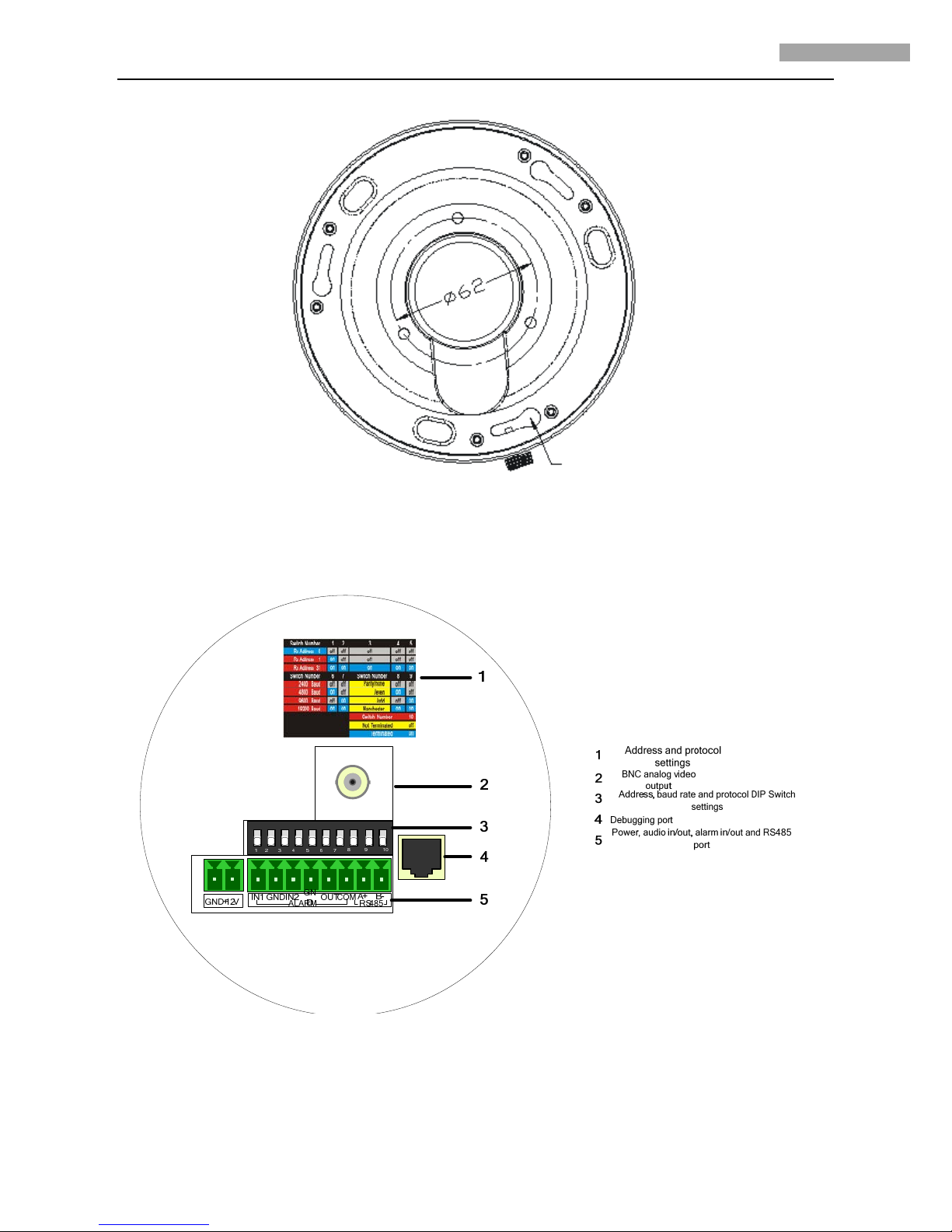
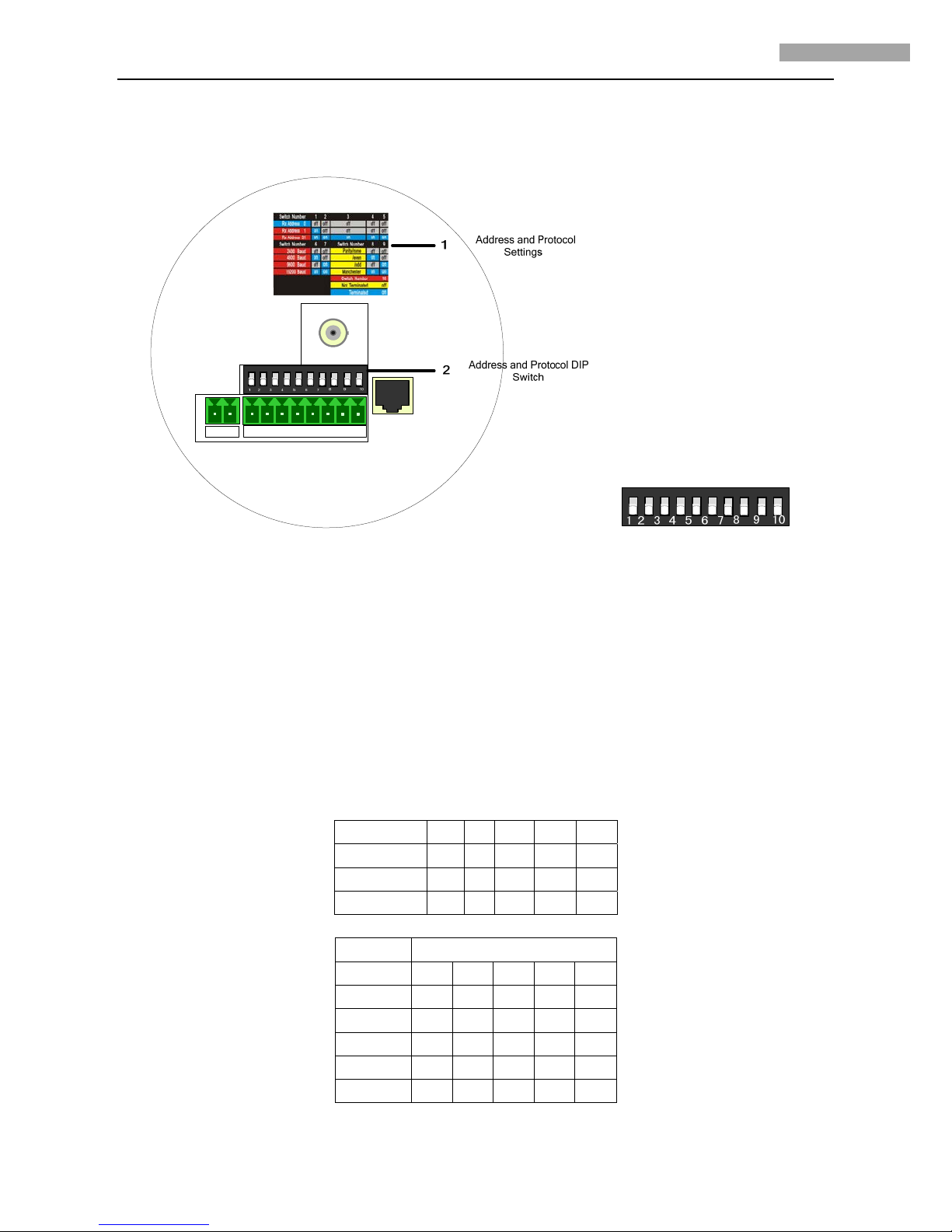
1. Configure the dome address, baud rate and other settings through DIP switch located on the bottom board of the dome drive, as
shown in Figure 1.2.3 and Figure 1.2.4. Please refer to Section 1.4 DIP Switch Settings for setting address, baud rate,
communication protocol, etc.
1: Address and protocol settings 2: BNC analog video output
3: Address, baud rate and protocol DIP Switch settings
4: Debugging port 5: Power, alarm in/out and RS485 port
Figure 1.2.3 Interconnect Board of Dome (High Speed Dome)
Page 8
4 Inch Speed Dome Installation Manual V2.0.0
7
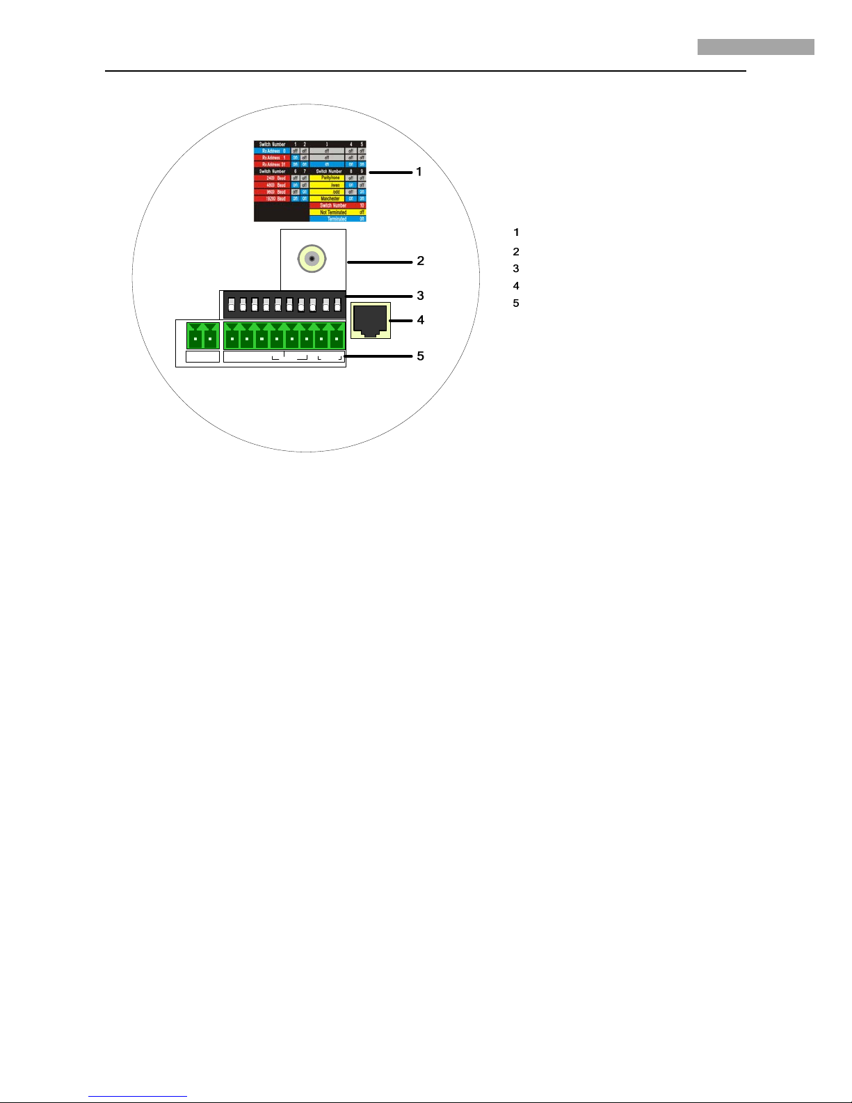
12345 67
8
10
9
AIN
OU
T
A+ B-
IN
GND
ALA
RM
RS48
5
AOU
T
GN
D
+12V
Address and protocol settings
BNC analog video output
Address, baud rate and protocol DIP Switch
settings
Network interface
Power, audio in/out, alarm in/out and RS485
port
1: Address and protocol settings 2: BNC analog video output
3: Address, baud rate and protocol DIP Switch settings
4: Network interface 5: Power, audio in/out, alarm in/out and RS485 port
Figure 1.2.4 Interconnect Board of Dome (Network Speed Dome)
2. Connect the power cord, alarm in/out lines, RS485 control line and video cable, as shown in Figure 1.2.3 and Figure 1.2.4.
Note: The high speed dome model provides 2 alarm inputs and no audio in/out; while the network speed dome model provides
audio in/out and 1 alarm input.
Operate the following steps to connect wiring:
(1) Unplug the connector (green) from the dome circuit board.
(2) Use the screwdriver to loosen the screw in the connector, insert the signal control line under the spring washer and finally
tighten the screw.
(3) Plug the pin connector into the corresponding socket (green) on the circuit board.
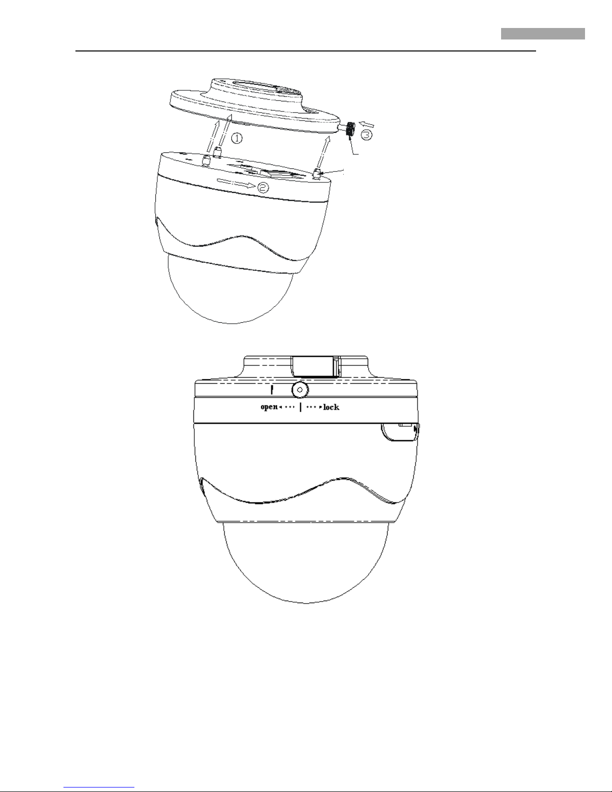
3. Install the dome drive
(1) Insert the three ball studs into the corresponding mounting grooves by lining up the I labels both on the mounting base and
the interconnect board of dome.
(2) Rotate the dome drive for approximately 15 degrees in anti-clockwise direction until it has firmly located at the mounting
base.
(3) Tighten the Philips pan head screws on the mounting base.
Page 9
4 Inch Speed Dome Installation Manual V2.0.0
8
Ball stud
Phillips pan head scre
w
Figure 1.2.5 Install Dome
Figure 1.2.6 Completion of Dome Installation
1.3 Initial Settings
Address code: 0
Baud rate: 2400
120Ω terminator: OFF
Page 10
4 Inch Speed Dome Installation Manual V2.0.0
9
1.4 DIP Switch Settings
Figure 1.2.7 DIP Switch for Address and Protocol Settings
The dome provides a DIP switch for setting the dome address, baud rate, protocol, etc. As shown in Figure 1.2.7, ON=1, OFF=0;
positions 1-5 of DIP switch are used for setting the dome address, positions 6-7 for baud rate, positions 8-9 for parity and Manchester
code, and position 10 is for setting the connection of 120-ohm terminator. Refer to the following section for the specific settings:
Note: As the high speed dome is capable of being self-adaptive to PELCO-D, PELCO-P and PRIVATE-Code protocols, no DIP switch
settings for control protocol are required.
1.4.1 Address Settings
The positions 1-5 of DIP switch is used for setting the dome address:
Dome Address 1 2 3 4 5
0 OFF OFF OFF OFF OFF
1 ON OFF OFF OFF OFF
31 ON ON ON ON ON
Settings for address 0~31 are listed as below:
DIP Switch Settings
Address 1 2 3 4 5
0 OFF OFF OFF OFF OFF
1 ON OFF OFF OFF OFF
2 OFF ON OFF OFF OFF
3 ON ON OFF OFF OFF
4 OFF OFF ON OFF OFF
Page 11
4 Inch Speed Dome Installation Manual V2.0.0
10
5 ON OFF ON OFF OFF
6 OFF ON ON OFF OFF
7 ON ON ON OFF OFF
8 OFF OFF OFF ON OFF
9 ON OFF OFF ON OFF
10 OFF ON OFF ON OFF
11 ON ON OFF ON OFF
12 OFF OFF ON ON OFF
13 ON OFF ON ON OFF
14 OFF ON ON ON OFF
15 ON ON ON ON OFF
16 OFF OFF OFF OFF ON
17 ON OFF OFF OFF ON
18 OFF ON OFF OFF ON
19 ON ON OFF OFF ON
20 OFF OFF ON OFF ON
21 ON OFF ON OFF ON
22 OFF ON ON OFF ON
23 ON ON ON OFF ON
24 OFF OFF OFF ON ON
25 ON OFF OFF ON ON
26 OFF ON OFF ON ON
27 ON ON OFF ON ON
28 OFF OFF ON ON ON
29 ON OFF ON ON ON
30 OFF ON ON ON ON
31 ON ON ON ON ON
Page 12
4 Inch Speed Dome Installation Manual V2.0.0
11
1.4.2 Baud Rate Settings
The positions 6-7 of DIP switch are used for setting the baud rate of dome, respectively as 2400bps, 4800bps, 9600bps and 19200bps.
For baud rate out of the above range, the default setting is 2400bps. Refer to the following table:
Baud Rate 6 7
2400 OFF OFF
4800 ON OFF
9600 OFF ON
19200 ON ON
1.4.3 Protocol Settings (High Speed Dome)
The positions 8-9 of DIP switch are used for setting the communication protocols of dome. Refer to the following table:
8 9
Bosch Manchester OFF ON
AD Manchester ON ON
Self-adaptive Others
1.4.4 Parity and Manchester Code Settings (Network Speed Dome)
The positions 8-9 of DIP switch are used for setting the parity and Manchester protocol of dome. Refer to the following table (network
speed dome model does not support Manchester code protocol):
Parity/Manchester 8 9
None OFF OFF
Odd ON OFF
Even OFF ON
Manchester ON ON
1.4.5 Terminating Resistor Settings
The position 10 of DIP switch is used for setting the RS-485 120-ohm terminator of dome.
Note: When multiple speed domes are connected to the control device, the last dome unit should be connected with a 120-ohm
terminator.
10
Not Terminated OFF
Terminated ON
1.5 Alarm In/Out Connections
The high speed dome can be connected with 2 alarm inputs (0~12VDC) and 1 alarm output; and the network high speed dome is
allowed to connect with 1 alarm input (0~12VDC) and 1 alarm output. Refer to the following diagram:
Page 13

12
4 Inch Speed Dome Installation Manual V2.0.0
The alarm provides the relay output (no voltage), and the external power supply is required when it connects to the alarm device. For
DC power supply (left diagram), the input voltage must be within the range of 12VDC, 30mA. For AC power supply, the external relay
must be used (right diagram) so as to prevent damages to the unit and avoid risk of electric shock.
Page 14

4 Inch Speed Dome Installation Manual V2.0.0
13
Chapter 2 Mounts Dimension
2.1 Long-arm Wall Mount
Stud
Stu d
Page 15

4 Inch Speed Dome Installation Manual V2.0.0
14
2.2 Short-arm Wall Mount
Stud
2.3 Corner Adapter
Stud
Stud
Page 16

4 Inch Speed Dome Installation Manual V2.0.0
15
2.4 Pole Adapter
Stud
2.5 Pendant Adapter
Page 17

4 Inch Speed Dome Installation Manual V2.0.0
16
Chapter 3 Wall Mounting Applications
3.1 Mounting Components
Wall Mount
Applicable to indoor/outdoor pendant domes.
Mounting Accessories
Nuts and Flat Washers
Pendant Adapter
Page 18

4 Inch Speed Dome Installation Manual V2.0.0
17
3.2 Wall Mounting Instructions
The wall mounting is applicable to the indoor/outdoor solid wall construction which should comply with the following mounting
requirements:
The wall must be thick enough to install the expansion screws.
The wall must be capable of supporting up to 8 times the total load of the dome and its accessories.
Step1: Drill mounting holes in the wall and install the expansion screws
Drill four holes in the wall according to the mounting locations, and then insert M6 expansion screws (not supplied) into the mounting
holes.
Step2: Secure the wall mount to the wall
Fasten the expansion screws through the wall mount and gasket by using four hex nuts with flat washers to secure the wall mount to
the wall.
Page 19

4 Inch Speed Dome Installation Manual V2.0.0
18
Step3: Install dome to the mount
Feed cables through the opening on top of the back box, screw the back box into the threads in the mount, and then use M3 screws to
secure the dome. Refer to Section 1.2 for installation instructions.
Note: Follow the same instructions described above for the Short-arm Wall Mount installation. For outdoor applications, please adopt
the water-proof measures. The Short-arm Wall Mount is not recommended for outdoor applications.
Page 20

4 Inch Speed Dome Installation Manual V2.0.0
19
Chapter 4 Corner Mounting Applications
4.1 Mounting Components
Wall Mount
Applicable to the indoor/outdoor pendant domes with the use of corner adapter, wall adapter or pole adapter.
Corner Adapter
For use with the wall mount in the corner mounting applications.
Mounting Accessories
Hex Screws (M8×30), Nuts, Spring Washers and Flat Washers
Pendant Adapter
Page 21

4 Inch Speed Dome Installation Manual V2.0.0
20
4.2 Corner Mounting Instructions
The corner mounting is applicable to the indoor/outdoor 90° solid corner construction which should comply with the following
mounting requirements:
The wall must be thick enough to install the expansion screws.
The wall must be capable of supporting up to 8 times the total load of the dome and its accessories.
Step1: Install the corner adapter
Drill four holes in the corner according to the mounting locations, and then insert M6 expansion screws (not supplied) into the holes.
Pull the power cord, video cable and control line through the opening of the corner adapter. Secure the corner adapter to the corner by
using nuts and washers to tighten the four expansion screws.
Note: Make sure the cables have enough length. For outdoor applications, please apply the sealant around the cable opening to prevent
water.
Page 22

4 Inch Speed Dome Installation Manual V2.0.0
21
Step2: Secure the wall mount to the corner
Apply four hex screws with the spring washers to the corner adapter through the wall mount and gasket.
Note: When tightening the screw, it is better to compress the spring washer firstly and then rotate half a round so as to maintain
required waterproof effect without damaging the threads.
Step3: Install dome to the mount
Feed the cables through the opening on top of the back box, and attach the dome to the mount. Finally, use M3 screws to secure the
two units. Refer to Section 1.2 for installation instructions.
Note: Follow the same instructions described above for the Short-arm Corner Mount installation. For outdoor applications, please
adopt the water-proof measures. The Short-arm Wall Mount is not recommended for outdoor applications.
Page 23

4 Inch Speed Dome Installation Manual V2.0.0
22
Chapter 5 Pole Mounting Applications
5.1 Mounting Components
Wall Mount
Applicable to indoor/outdoor pendant domes with the use of corner adapter, wall adapter or pole adapter.
Pole Adapter
For use with the wall mount in the pole mounting applications.
Page 24

4 Inch Speed Dome Installation Manual V2.0.0
23
Stainless Steel Straps
For use with the pole adapter, with the following dimensions selectable:
φ59-82mm, φ84-108mm, φ103-127mm, φ130-152mm, φ155-178mm, φ180-203mm, φ194-216mm;
Customized dimensions can also be provided according to user’s demand.
Mounting Accessories
Hex Screws (M8×30) and Spring Washers
Pendant Adapter
5.2 Pole Mounting Instructions
The pole mounting is applicable to the indoor/outdoor solid pole construction which should comply with the following mounting
requirements:
Page 25

4 Inch Speed Dome Installation Manual V2.0.0
24
The diameter of pole must be constituent with the mounting dimensions of the stainless steel straps.
The pole construction must be capable of supporting up to 8 times the total load of the dome and its accessories.
Step1: Assemble the pole mount adapter
Use a screwdriver to loosen the three stainless steel straps and then insert them through the rectangle holes on the pole adapter.
Step2: Install pole adapter
Feed the control line, video cable and power cable through the central opening and secure the three stainless steel straps to the pole,
and finally use the screwdriver to fasten the screws at the steel straps.
Note: For outdoor applications, please adopt the water-proof measures.
Page 26

4 Inch Speed Dome Installation Manual V2.0.0
25
Step3: Install wall mount assembly
Screw four hex screws with the spring washers to the pole adapter through the wall mount and gasket.
Step4: Install dome to the mount
Feed the cables through the opening on top of the back box, and attach the dome to the mount, and finally use M3 screws to secure the
dome. Refer to Section 1.2 for installation instructions.
Note: Follow the same instructions described above for the Short-arm Corner Mount installation. For outdoor applications, please
adopt the water-proof measures. The Short-arm Wall Mount is not recommended for outdoor applications.
Page 27

4 Inch Speed Dome Installation Manual V2.0.0
26
Chapter 6 Pendant Mounting Applications
6.1 Mounting Components
Mounting Base
Applicable to pendant domes with the use of the pendant pole and pole adapter.
Pendant Pole
Pendant Adapter
Page 28

4 Inch Speed Dome Installation Manual V2.0.0
27
6.2 Pendant Mounting Instructions
The pendant mounting is applicable to the indoor/outdoor solid ceiling construction which should comply with the following mounting
requirements:
The ceiling must be thick enough to mount the expansion screws.
The ceiling must be capable of supporting up to 8 times the total load of the dome and its accessories.
Step1: Install the mounting base
Drill four φ6 holes in the ceiling according to the fastener holes locations of the mounting base, and then insert M6 expansion screws
(not supplied) into the holes. Pull the power cord, video cable and control line through the opening at the mounting base. Secure the
mounting base to the corner by using nuts and washers to tighten the four expansion screws.
Note: Make sure the cables have enough length. For outdoor applications, please apply water-proof measures between the ceiling
surface and mounting base and around the cables opening. The pendant mounting application is not recommended for outdoor
environment where directly suffers rain.
Page 29

28
4 Inch Speed Dome Installation Manual V2.0.0
Step2: Install the pendant pole
Swivel the pendant adapter into the matching pendant pole and then use the retainer screws to secure the two parts. Pull out the cables
through the pendant pole and screw the pendant pole into the mounting base and use the set screws to secure the two parts as well.
Note: For outdoor applications, please apply the water-proof thread compound to the threads.
Step3: Install dome to the mount
Feed the cables through the opening on top of the back box, and attach the dome to the pendant pole, and finally use M3 screws to
secure the dome. Refer to Section 1.2 for installation instructions.
Note: In case of insufficient ceiling height, directly attach the dome to the mounting base without use of pendant pole, as shown in the
figure right above.
Page 30

4 Inch Speed Dome Installation Manual V2.0.0
29
Chapter 7 In-ceiling Mounting Applications
7.1 Installation Conditions
The in-ceiling mounting is applicable to the indoor ceiling construction which should comply with the following mounting
requirements:
The height above the ceiling must be more than 250mm.
The ceiling must be with the thickness of 5~40mm.
The ceiling must be capable of supporting up to 5 times the total load of the dome and its accessories.
7.2 In-ceiling Mounting Instructions
Step1: Attach dome to the mounting base
Take out the drill drawing from the package and use it as a template to draw a circle on the ceiling and then cut out the circle.
Note: The allowable tolerance of diameter is 2mm.
Drill Drawing
Page 31

4 Inch Speed Dome Installation Manual V2.0.0
30
Step2: Install the dome to the mounting hole and then tighten the key locks to secure the dome. Finally, attach the trim ring to the
dome.
Page 32

4 Inch Speed Dome Installation Manual V2.0.0
31
Step3: Connect cables
Connect all wiring to corresponding sockets located on the circuit board. Please refer to Section 1.2 for specific instructions.
Page 33

4 Inch Speed Dome Installation Manual V2.0.0
32
Appendix 1 RS485 Bus Connection
1. General Property of RS485 Bus
According to RS485 industry bus standard, RS485 is a half-duplex communication bus which has 120Ω characteristic impendence, the
maximum load ability is 32 payloads (including controller device and controlled device).
2. RS485 Bus Transmission Distance
When using 0.56mm (24AWG) twisted-pair line, according to different baud rate, the max transmission distance theory table is shown
as below:
Baud Rate Max Distance
2400BPS 1800m
4800BPS 1200m
9600BPS 800m
The transmission distance will be decreased if we use the thinner cable, or use this product under the strong electromagnetic
interference situation, or there are lots of devices are added to the bus; on the contrary, the transmission distance will be increased.
3. Connection Method and Terminal Resistance
1) RS485 industry bus standard require daisy-chain connection method between any devices, both sides have to connect a 120Ω
terminal resistance (show as Diagram 1), the simplified connection method is shown as diagram 2, but the distance of “D”
should not be too long.
Diagram 1
Diagram 2
2) Connection of 120Ω terminal resistor
The 120Ω terminal resistor can be connected through the DIP switch on the communications board, as shown in Figure3. For a new
dome, the 120Ω matching resistor is defaulted as unconnected, switch on the eighth bit of SW2, it will be connected. Conversely,
switch off the eighth bit of SW2, it will be unconnected.
Page 34

4 Inch Speed Dome Installation Manual V2.0.0
33
Figure 3
4. Problems in the Practical Application
Normally, users adopt star-shape connection method in construction, under this situation, the terminal resistors must be connected
between two farthest devices (as Figure 4, 1# and 15#), but this connection method is not satisfy the requirement of the RS485
industry standard so that it will lead to some problems such as signal reflection, anti-jamming ability decline when the devices are
faraway. At this time, the dome will be uncontrollable, or self-running, etc.
Figure 4
For such case, the best way is adding a RS485 distributor. This product can effectively change the star-shape connection to which
satisfies the requirement of RS485 industry standard, in order to avoid those problems and improve the communication reliability.
Show as figure 5.
Page 35

4 Inch Speed Dome Installation Manual V2.0.0
34
Figure 5
1. FAQ of RS485 Bus
Page 36

4 Inch Speed Dome Installation Manual V2.0.0
35
Appendix 2 24VAC Wire Gauge & Transmission Distance
The following table has described the recommended max. distance adopted for the certain wire gauge when the 24VAC voltage loss
rate is less than 10%. For the AC driven device, the maximum voltage loss rate allowable is 10%. For example, for a device with the
rating power of 80VA which is installed at a distance of 35 feet (10m) away from the transformer, then the minimum wire gauge
required is 0.8000mm.
Wire Gauge
mm
Distance
feet(m)
Power (va)
Page 37

36
4 Inch Speed Dome Installation Manual V2.0.0
Appendix 3 Table of Wire Gauge Standards
American Wire Gage
AWG
(British)Standard Wire Gauge
SW G
Bare Wire Gauge
( mm)
Cross-sec tional Area
of
mm
Bare Wire
2
 Loading...