

HIKVISION DS-9508NIRT, DS-9516NIST, DS-9532NIRT, DS-9516NIRT, DS-8508NIST Quick Operation Manual
...Page 1

Network Video Recorder
Quick Operation Guide
UD.6L0202B1351A01
Page 2

Quick Operation Guide of Network Video Recorder
1
TABLE OF CONTENTS
NVR Pre-Installation ....................................................................................................................................... 2
NVR Installation .............................................................................................................................................. 2
Hard Disk Installation ..................................................................................................................................... 2
Front Panels ...................................................................................................................................................... 6
DS-9500NI-ST/RT Front Panel .................................................................................................................. 6
DS-8500NI-ST Front Panel ........................................................................................................................ 6
Rear Panel ........................................................................................................................................................ 7
Connections ...................................................................................................................................................... 8
Wiring of Alarm Input ................................................................................................................................ 8
Wiring of Alarm Output ............................................................................................................................. 8
Using of Alarm Connectors ........................................................................................................................ 8
Specifications .................................................................................................................................................... 9
DS-9500NI-ST ........................................................................................................................................... 9
DS-9500NI-RT ......................................................................................................................................... 10
DS-8500NI-ST ......................................................................................................................................... 11
HDD Storage Calculation Chart ................................................................................................................... 12
Basic Operation .............................................................................................................................................. 13
Power On ................................................................................................................................................. 13
Power Off ................................................................................................................................................. 13
Login and Exit.......................................................................................................................................... 13
Accessing the Device by Client Software ........................................................................................ 13
Accessing the Device by Web Browser ............................................................................................ 14
Camera Management ............................................................................................................................... 15
Quick Adding IP Cameras ................................................................................................................ 15
Manually Adding IP Cameras .......................................................................................................... 16
Live View ................................................................................................................................................. 16
Getting Live View ............................................................................................................................ 17
Multi-window Division .................................................................................................................... 17
One-touch RAID Configuration ............................................................................................................... 18
Recording and Capturing ......................................................................................................................... 19
Manual Recording and Capturing .................................................................................................... 19
Schedule Recording and Capturing .................................................................................................. 19
Playback ................................................................................................................................................... 21
One-touch Backup.................................................................................................................................... 23
Page 3

Quick Operation Guide of Network Video Recorder
2
Thank you for purchasing our product. If there is any question or request, please do not hesitate to contact dealer.
This manual is applicable to the models listed in the following table.
Series
Model
Type
9500NI-ST
DS-9508NI-ST
DS-9516NI-ST
DS-9532NI-ST
DS-9564NI-ST
Network Video Recorder
9500NI-RT
DS-9508NI-RT
DS-9516NI-RT
DS-9532NI-RT
DS-9564NI-RT
Network Video Recorder
8500NI-ST
DS-8508NI-ST
DS-8516NI-ST
DS-8532NI-ST
DS-8564NI-ST
Network Video Recorder
NVR Pre-Installation
The DS-9500/8500NI-ST and DS-9500NI-RT Series NVR is highly advanced surveillance equipment that should
be installed with care. Please take into consideration the following precautionary steps before installation of the
NVR.
1. Keep all liquids away from the NVR.
2. Install the NVR in a well-ventilated and dust-free area.
3. Ensure environmental conditions meet factory specifications.
4. Install a manufacturer recommended HDD.
NVR Installation
During the installation of the NVR:
1. Use brackets for rack mounting.
2. Ensure there is ample room for audio and video cables.
3. When routing cables, ensure that the bend radius of the cables are no less than five times than its diameter.
4. Connect both the alarm and RS-485 cable.
5. Allow at least 2cm (≈0.75in) of space between racks mounted devices.
6. Ensure the NVR is grounded.
7. Environmental temperature should be within the range of -10 ºC ~ 55 ºC , 14ºF ~ 131ºF.
8. Environmental humidity should be within the range of 10% ~ 90%.
Hard Disk Installation
Disconnect the power from the NVR before installing a hard disk drive (HDD). A factory recommended HDD
should be used for this installation.
Tools Required: Screwdriver.
Steps (for DS-9500NI-ST/RT):
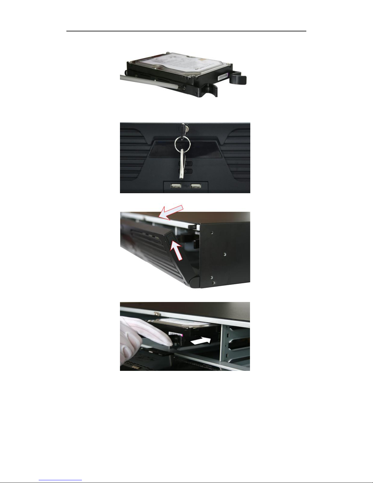
1. Fasten the hard disk mounting handle to the hard disk with screws.
Page 4
Quick Operation Guide of Network Video Recorder
3
2. Insert the key and turn in clockwise direction to open the panel lock.
3. Press the buttons on the panel of two sides and open the front panel.
4. Insert the hard disk along the slot until it is placed into position.
5. Repeat the above steps to install other hard disks onto the NVR. After having finished the installation of all
hard disks, close the front panel and lock it with the key again.
Page 5
Quick Operation Guide of Network Video Recorder
4
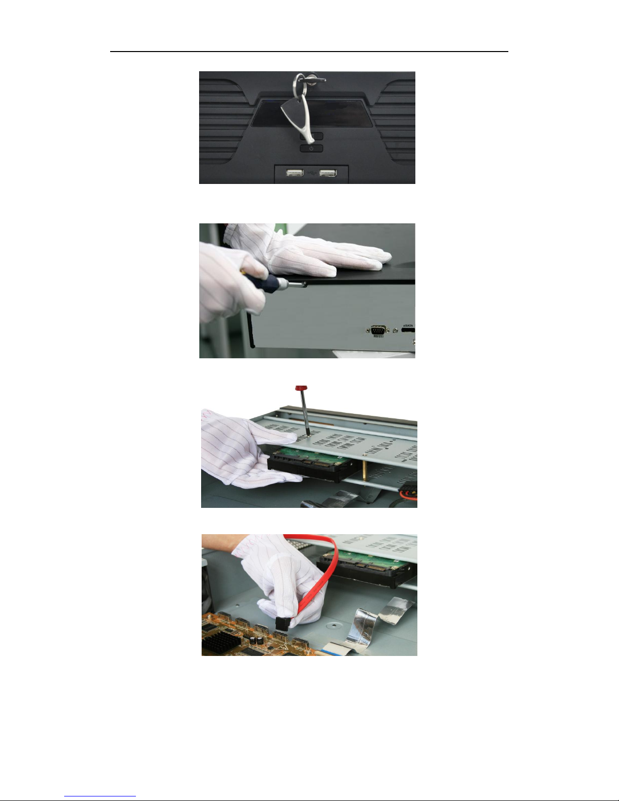
Steps (for DS-8500NI-ST):
1. Remove the cover from the NVR by unfastening the screws on the back and side.
2. Insert the HDD to the HDD rack and secure the HDD with screws.
3. Connect one end of the data cable to the motherboard of NVR and the other end to the HDD.
4. Connect the power cable to the HDD.
Page 6

Quick Operation Guide of Network Video Recorder
5
5. Re-install the cover of the NVR and fasten screws.
Page 7

Quick Operation Guide of Network Video Recorder
6
Front Panels
DS-9500NI-ST/RT Front Panel
DS-8500NI-ST Front Panel
No.
Name
Description
1
Status
LED
Indicators
Power
Turning red indicates power is connected but the system isn’t
running; turning blue indicates power is connected and the system is
running.
Alarm
Alarm LED turns red when a sensor alarm is detected.
TX/RX
TX/RX LED flashes blue when network connection is functioning
properly.
HDD
HDD LED flashes red when data is being read from or written to
HDD.
Ready
Ready LED turns blue when NVR is functioning properly.
Archive
(for DS-8500NI-ST
series)
Archive LED flashes blue when data is being backed up.
2
Backup Button
Back up video files.
3
USB Ports
Universal Serial Bus (USB) ports for additional devices such as USB
mouse and USB Hard Disk Drive (HDD).
4
Power Button
Powers NVR on/off.
5
Channel Status Indicators
Blue indicates recording, red indicates network connection, and
purple indicates recording and network connection.
6
Front Panel Lock
(for DS-9500NI-ST&RT series)
You can lock or unlock the panel by the key.
Page 8
Quick Operation Guide of Network Video Recorder
7
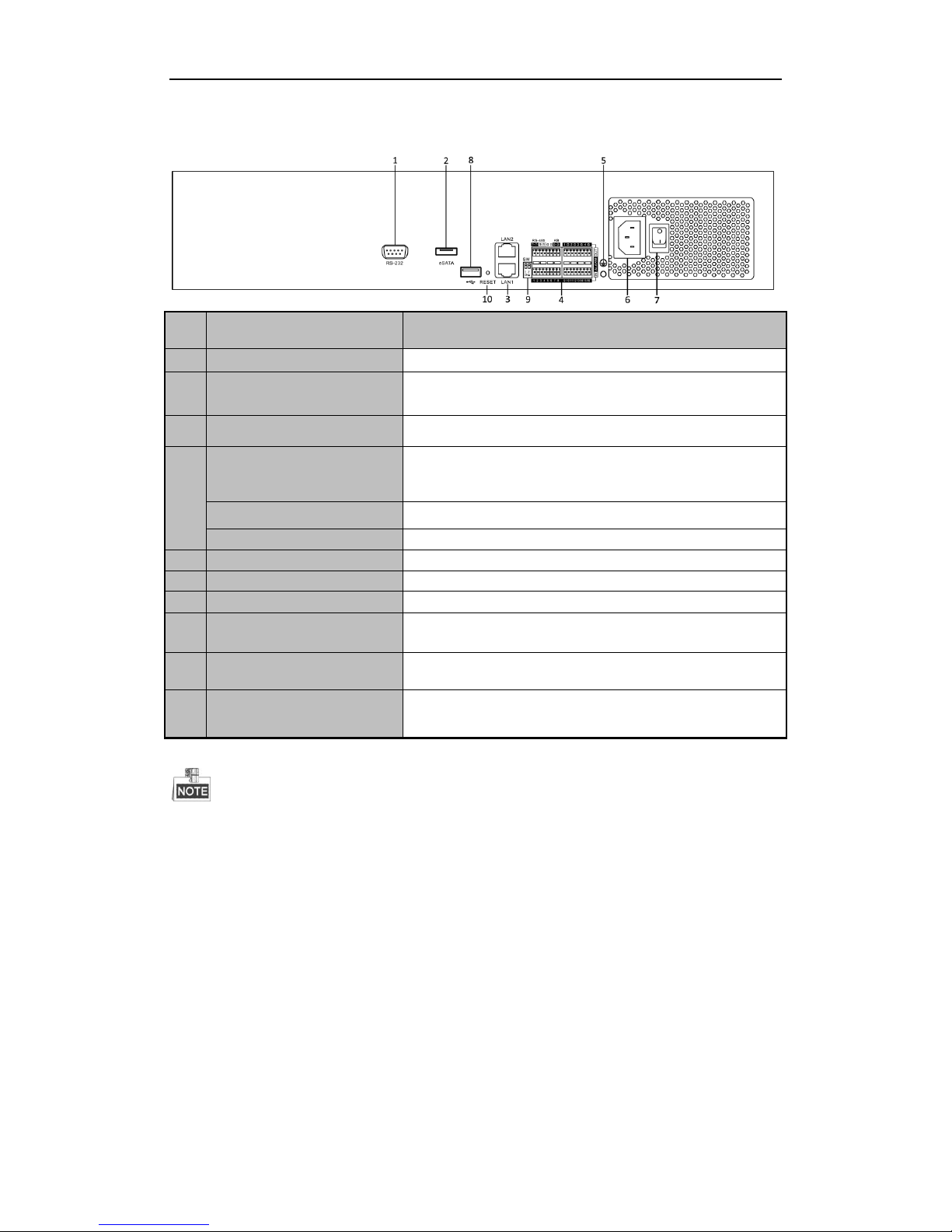
Rear Panel
No.
Item
Description
1
RS-232
Connects to RS-232 devices.
2
eSATA
Backup/extended storage interface, connect to external SATA disk,
DVD-R/W, disk array, etc.
3
LAN
2 network interfaces.
4
RS-485
Connect to RS-485 devices, e.g., P/T receiver, etc. Use the T+ and T
-terminals of RS-485 interface to connect to the R+ and Rterminals of the receiver.
ALARM IN
16 relay alarm inputs
ALARM OUT
4 relay alarm outputs
5
GND
Grounding
6
POWER
100 ~ 240 VAC power supply
7
Power Switch
Switch for turning on/off the device.
8
USB
Universal Serial Bus (USB) ports for additional devices such as USB
mouse and USB Hard Disk Drive (HDD).
9
RS-485 Matching
Resistor Switch (SW)
Connection of 120-ohm terminator for RS-485 bus. ON=connected;
OFF=disconnected.
10
RESET
Press and hold it for 10 seconds to reset all parameters to default
settings.
The RS-485 interface of the device is reserved for future use.
Page 9

Quick Operation Guide of Network Video Recorder
8
Connections
Wiring of Alarm Input
The alarm input is an open/closed relay. To connect the alarm input to the device, use the following diagram.
If the alarm input is not an open/close relay, please connect an external relay between the alarm input and the
device.
Wiring of Alarm Output
To connect to an alarm output (AC or DC load), use the following diagram:
DC Load Connection Diagram AC Load Connection Diagram
For DC load, the jumpers can be used within the limit of 12V/1A safely.
To connect an AC load, jumpers should be left open (you must remove the jumper on the motherboard in the
NVR). Use an external relay for safety (as shown in the figure above).
There are 4 jumpers (JP1, JP2, JP3, and JP4) on the motherboard, each corresponding with one alarm output. By
default, jumpers are connected. To connect an AC load, jumpers should be removed.
Example:
If you connect an AC load to the alarm output 3 of the NVR, then you must remove the JP 3.
Using of Alarm Connectors
To connect alarm devices to the NVR:
1. Disconnect pluggable block from the ALARM IN /ALARM OUT terminal block.
2. Unfasten stop screws from the pluggable block, insert signal cables into slots and fasten stop screws. Ensure
signal cables are in tight.
3. Connect pluggable block back into terminal block.
Page 10

Quick Operation Guide of Network Video Recorder
9
Specifications
DS-9500NI-ST
Model
DS-9508NIST
DS-9516NIST
DS-9532NIST
DS-9564NIST
Video input
IP video input
8-ch
16-ch
32-ch
64-ch
Recording
Parameters
Recording resolution
5MP/3MP/1080p/UXGA/720p/VGA/4CIF/DCIF/2CIF/CIF/QCIF
Frame rate
Main stream: 25 fps (P) / 30 fps (N)
Sub-stream: 25 fps (P) / 30 fps (N)
Network
Incoming bandwidth
40Mbps
80Mbpss
160Mbps
160Mbps
Outgoing bandwidth
240Mbps
240Mbps
160Mbps
160Mbps
Remote Connection
128
Hard disk
SATA
8 SATA interfaces
eSATA
1 eSATA interface
Capacity
Up to 4TB capacity for each HDD
External
interface
Network interface
2 RJ-45 10 /100 /1000 Mbps self-adaptive Ethernet interfaces
Serial interface
RS-232; RS-485 interface; Keyboard;
USB interface
3 × USB 2.0
Alarm in
16
Alarm out
4
General
Power supply
100 ~ 240 VAC, 6.3 A, 50 ~ 60 Hz
Consumption
(without hard disk)
≤ 45W
Working
temperature
-10 ºC ~ +55 ºC (14 ºF ~ 131 ºF)
Working humidity
10 % ~ 90 %
Chassis
19-inch rack-mounted 2U chassis
Dimensions
(W × D × H)
445 × 470 ×90 mm (17.5" ×18.5"× 3.5")
Weight
(without hard disk)
≤ 8 Kg (17.64 lb)
Page 11

Quick Operation Guide of Network Video Recorder
10
DS-9500NI-RT
Model
DS-9508NIRT
DS-9516NIRT
DS-9532NIRT
DS-9564NIRT
Video input
IP video input
8-ch
16-ch
32-ch
64-ch
Recording
Parameters
Recording resolution
5MP/3MP/1080p/UXGA/720p/VGA/4CIF/DCIF/2CIF/CIF/QCIF
Frame rate
Main stream: 25 fps (P) / 30 fps (N)
Sub-stream: 25 fps (P) / 30 fps (N)
Network
Incoming bandwidth
40Mbps
80Mbps
160Mbps
160Mbps
Outgoing bandwidth
240Mbps
240Mbps
160Mbps
160Mbps
Remote Connection
128
Hard disk
SATA
8 SATA interfaces
eSATA
1 eSATA interface
Capacity
Up to 4TB capacity for each HDD
Disk array
Array type
RAID0, RAID1, RAID5, RAID10
Number of array
8
Number of virtual
disk
8
External
interface
Network interface
2 RJ-45 10 /100 /1000 Mbps self-adaptive Ethernet interfaces
Serial interface
RS-232; RS-485 interface; Keyboard;
USB interface
3 × USB 2.0
Alarm in / out
16 / 4
General
Power supply
100 ~ 240 VAC, 6.3 A, 50 ~ 60 Hz
Consumption
(without hard disk)
≤ 45 W
Working
temperature
-10 ºC ~ +55 ºC (14 ºF ~ 131 ºF)
Working humidity
10 % ~ 90 %
Chassis
19-inch rack-mounted 2U chassis
Dimensions
(W × D × H)
445 × 470 ×90 mm (17.5" ×18.5"× 3.5")
Weight
(without hard disk)
≤ 8 Kg (17.64 lb)
Page 12

Quick Operation Guide of Network Video Recorder
11
DS-8500NI-ST
Model
DS-8508NIST
DS-8516NIST
DS-8532NIST
DS-8564NIST
Video input
IP video input
8-ch
16-ch
32-ch
64-ch
Recording
Parameters
Recording resolution
5MP/3MP/1080p/UXGA/720p/VGA/4CIF/DCIF/2CIF/CIF/QCIF
Frame rate
Main stream: 25 fps (P) / 30 fps (N)
Sub-stream: 25 fps (P) / 30 fps (N)
Network
Incoming bandwidth
40Mbps
80Mbps
160Mbps
160Mbps
Outgoing bandwidth
240Mbps
240Mbps
160Mbps
160Mbps
Remote Connection
128
Hard disk
SATA
8 SATA interfaces
eSATA
1 eSATA interface
Capacity
Up to 4TB capacity for each HDD
External
interface
Network interface
2 RJ-45 10 /100 /1000 Mbps self-adaptive Ethernet interfaces
Serial interface
RS-232, RS-485, Keyboard
USB interface
3 × USB 2.0
Alarm in
16
Alarm out
4
Others
Power supply
100 ~ 240 VAC, 6.3 A, 50 ~ 60 Hz
Consumption
(without hard disk)
≤ 45 W
Working
temperature
-10 ºC ~ +55 ºC (14ºF ~ 131ºF)
Working humidity
10 % ~ 90 %
Chassis
19-inch rack-mounted 2U chassis
Dimensions
(W × D × H)
445 × 470 ×90 mm (17.5" ×18.5"× 3.5")
Weight
(without hard disk)
≤ 8 Kg (17.64 lb)
Page 13

Quick Operation Guide of Network Video Recorder
12
HDD Storage Calculation Chart
The following chart shows an estimation of storage space used based on recording at one channel for an hour at a
fixed bit rate.
Bit Rate
Storage Used
96K
42M
128K
56M
160K
70M
192K
84M
224K
98M
256K
112M
320K
140M
384K
168M
448K
196M
512K
225M
640K
281M
768K
337M
896K
393M
1024K
450M
1280K
562M
1536K
675M
1792K
787M
2048K
900M
4096K
1800M
8192K
3600M
16384K
7200M
Please note that supplied values for storage space used is just for reference. The storage values in the chart
are estimated by formulas and may have some deviation from actual value.
Page 14

Quick Operation Guide of Network Video Recorder
13
Basic Operation
Power On
If the power LED indicator on the front panel is off, please check whether the power supply is plugged into an
electrical outlet and the power switch on the rear panel is turned on; the LED turns red, indicating the device is
receiving power.
When the LED is red, please press the Power button on the front panel. The Power indicator will turn blue. The
device will begin to start.
It is highly recommended that an Uninterruptible Power Supply (UPS) be used in conjunction with the
device.
When the Ready indicator turns blue, the device is powered on and works properly.
Power Off
Standard Shutdown
Press and hold the POWER button for 3 seconds; the device will enter power off process, when power indicator
turns red, turn off the power switch on the rear panel.
Other Methods of Shutdown
• Shutdown with Power Switch
Please try to avoid shutting down the device by turning off the power switch on the rear panel (especially
during recording).
• Shutdown by Unplugging Power Supply
Please try to avoid shutting down the device by unplugging power supply (especially during recording).
Login and Exit
Accessing the Device by Client Software
Steps:
1. Click “Start””All Programs”“iVMS-4200 Station”“VMS Software”“iVMS-4200 Client” to start
the client software.
2. Enter the Device Management interface and click Add Device button to pop up the detail information editing
dialog box. Edit the Nickname, Address, Port, User Name and Password, and then click the Add button to
add it.
Page 15

Quick Operation Guide of Network Video Recorder
14
3. If the SADP software has been installed on PC, you can use it to automatically search the online devices in
the same subnet with your PC.
The detected online devices are displayed on the bottom of the interface. Click to select the device and click
the Add to Client button to pop up the detail information editing dialog box.
Edit the Nickname, Address, Port, User Name and Password, and then click the Add button to add it.
For detailed instructions, please refer to the User Manual of iVMS-4200.
Accessing the Device by Web Browser
Steps:
1. Open web browser, input the IP address of the device (e.g.,172.9.1.76) and then press the Enter Button. The
system will remind you to install the plug-in control. Click and install the plug-in control.
The system then will display the login interface as shown in the following figure:
Page 16

Quick Operation Guide of Network Video Recorder
15
On the top right corner, language is selectable between Chinese and English.
2. Input the correct user name and password, click Login to enter the live view interface, or it will pop up an
error box.
You can click Logout on the top-right corner to log out and return to the login interface.
The default IP address is 192.0.0.64.
The default user name is admin, and password is 12345.
You may use one of the following listed web browsers: Internet Explorer 6.0, Internet Explorer 7.0,
Internet Explorer 8.0, Internet Explorer 9.0, Internet Explorer 10.0, Apple Safari, Mozilla Firefox, and
Google Chrome.
The supported resolutions include 1024*768 and above.
When you log in for the first time, the system will remind you to install the Plug-in control. After the installation,
you can configure and manage the device remotely.
Camera Management
Purpose:
The main function of the NVR is to connect the network cameras and record videos. So before you can get a live
view or record of the video, you should add the network cameras to the connection list of the device.
You can enter the camera management interface by:
Configuration> Remote Configuration> Camera Management> IP Camera
Quick Adding IP Cameras
DS-8500/9500NI-ST and DS-9500NI-RT series NVR provides a function of remote auto-searching IP camera.
When there are supported IP cameras in the same network segment of a LAN with NVR, you can add them with
one button configuration function with default user name, password and port number.
Before applying Quick Add function, please make sure that IP camera is compatible with NVR and default
user name, password, and port number are not changed.
Steps:
1. Click Quick Add button, the on-line IP cameras will be listed as figure below:
Page 17

Quick Operation Guide of Network Video Recorder
16
2. Check the checkbox of the listed cameras and click the OK button to finish adding.
Manually Adding IP Cameras
Steps:
1. Click the Add button, and the interface is shown below:
2. Input the IP address or domain name of the network camera in the IP Camera Address text field, and user
name and password.
Before adding the network camera by domain name, make sure you have registered it on the DDNS
server.
3. Click the OK button to finish adding.
And the camera and its information will be added in the list of cameras.
Live View
The live view interface is shown in the figure below:
Page 18

Quick Operation Guide of Network Video Recorder
17
Live View Interface Descriptions
No.
Name
Description
1
Channel List
Displays the list of channels and the playing and recording status of each
channel.
The stream type can be switched by clicking the icon before the channel name:
stands for main stream and for sub-stream.
2
Live View Window
Displays the image of channel, and multi-window division is supported.
3
Play Control Bar
Play control operations are supported.
4
PTZ Control
Pan, tilt, zoom operations are supported, as well as preset and patrol editing
and calling.
PTZ function can only be realized if the connected camera supports PTZ control.
5
Video Parameters
Configuration
Brightness, contrast, saturation and hue of the image can be edited.
Getting Live View
After choosing window division mode, select one window, and click on camera list to view the current
camera. If live view is on, the icon changes to .
Multi-window Division
When live view, the windows division can be selected by click the button on play control area.
It supports 1, 4, 9 and 16 windows division.
The change between different windows division modes will not stop the current live view.
Page 19

Quick Operation Guide of Network Video Recorder
18
One-touch RAID Configuration
Purpose:
For the DS-9500NI-RT series NVR, the disk array must be configured if you want to save recoring and log files
locally. Through one-touch configuration, you can quickly create the disk array. By default, the array type to be
created is RAID 5.
Before you start:
Install the iVMS-4200 client software, the disk array can only be configured through the client. As the default
array type is RAID 5, at least 3 HDDs must be installed in you device.
Steps:
1. Enter the HDD Management interface.
Device Management> Remote Config> Storage > Array
You can see information of physical disks.
2. Click One-touch Config to enter the One-touch Array Configuration interface.
3. Edit the array name in the Array text filed and click Apply button to start configuring array.
If you install 4 HDDs or above for one-touch configuration, a hot spare disk will be set by default. It is
recommended to set hot spare disk for automatically rebuilding the array when the array is abnormal.
There will be note if the operation is completed.
4. You can click Array tab to view the information of the successfully created array.
By default, one-key configuration creates an array and a virtual disk.
5. Click Virtual Disk tab to view the automatically created virtual disk.
Page 20

Quick Operation Guide of Network Video Recorder
19
By default, one-touch configuration adopts background initialization to initialize the RAID. By using
background initialization, the virtual disk can be used immediately.
6. You can see the information of the virtual disk in the HDD Information interface.
Recording and Capturing
Manual Recording and Capturing
Purpose:
You can manually trigger recording and capturing via the web browser, and the recording files and captured
picture will be saved in the local directory of your PC. Please refer to the User Manual for details of setting default
saving directory.
Before you start:
The channel for recording and capturing should be in the live view mode.
When the live view of the current channel is stopped, the recording or the capturing of this channel will be
stopped as well.
Manual Recording
Click icon to start recording of this channel. If the icon does not change to , it will pop up note message
“Recording failed”. When the recording is on, click to stop recording.
When multiple channels are in live view mode, you may click to start recording for all the channels, or click
to stop recording for all the channels.
If the free disk space is less than 500M, the web server will stop recording automatically.
Manual Capturing
Select a live view window, and click to capture image.
When the free disk space is less than 500M, capture image will be failed.
Schedule Recording and Capturing
In this section, we take the record schedule procedure as an example, and the same procedure can be
applied to configuring schedule for both recording and capturing. To schedule the automatic capture,
you need to choose the Capture tab in the Schedule interface.
Steps:
1. Enter Schedule Settings interface:
Configuration> Remote Configuraion> Camera Settings> Schedule Settings
2. Check the checkbox of Enable Record Schedule.
Page 21

Quick Operation Guide of Network Video Recorder
20
When IP camera is connected to the NVR, the all-day continuous recording of it starts automatically.
3. Click Edit button to enter setup page.
4. Select recording type in the drop-down list.
There are six recording types supported, including “Continuous”, “Motion Detection”, “Alarm”, “Motion
detection & Alarm”, “Motion detection | Alarm” and “VCA”.
“&” means recording is triggered when both the two events happened at the same time.
“|” means recording is triggered when either the event happened.
To realize recording triggered by event (the types mentioned above except “Continuous”), you need to
configure the alarm or motion settings first. Please refer to the User Manual for details.
5. Select one day in a week, and select All Day recording as you need. You may also set period recording
by disable All Day recording; there are 8 time periods in one day. Then you can select schedule
recording from the drop-down menu. Then you can also copy the settings to whole week or to any day
of the week.
Please make sure that each time period is not overlapped.
6. Click the Advanced button to set advanced parameters.
You can configure parameters of enable ANR (Automatic Network Replenishment), Pre-record time,
Post-record time, Stream Type, Record Audio and Expired Time.
Page 22

Quick Operation Guide of Network Video Recorder
21
Playback
Playing back by time is the only supported playback function when you success and configure the device by
web browser. You can refer to the User Manual of iVMS-4200 to get more information of playing back by
other conditions.
Steps:
1. Click Playback tab to enter playback interface.
Playback interface description
No.
Name
Description
1
Channel List
Displays the list of channels and the playing status of each channel.
2
Playback Window
Displays the image of channel.
3
Play Control Bar
Play control operations are supported.
4
Time Line
Displays the time bar and the records marked with different colors.
5
Playback Status
Displays the playback status, including channel number and playback speed.
6
Calendar
You can select the date to play.
Page 23

Quick Operation Guide of Network Video Recorder
22
Playback control buttons description
Area
Description
Area
Description
/
Play/Pause
Stop
Slow down
Speed up
Play by single frame
Capture
Stop all playback
Download
/
Video clip
/
Open/Close audio
Full screen
Transcoded playback
Reverse playback
Window division
2. Select a channel on the channel list. (Channel 1 is the default.)
3. Select a date in calendar. The date with recording files is marked as .
4. Click the Search button to search the matched recorded files. If there are search results, then they will be
shown in the time bar area.
You can drag the timeline to select the specific time, or input the time in the
pop-up box and click to locate the playback point. This will start the file playback from the specified
time.
Different file types will be indicated with different colors.
5. After searching file, click to play.
When playback, the playback status will indicate the channel number and status.
Page 24

Quick Operation Guide of Network Video Recorder
23
One-touch Backup
Steps:
1. Connect the backup device to the NVR.
2. Press the button on the front panel and the device will start to search the recording files in the
recent 24 hours, and then back up them to the connected device.
If the size of the searched files is larger than the free space of backup device, the more recent files will be
backed up preferentially.
The backup indicator flashes when backup is on.
A player will be copied to the backup device together with the backup record files.
0301001040106
Page 25

Quick Operation Guide of Network Video Recorder
24
 Loading...