

Hikvision DS-9508NI-S-2TB, DS-9508NI-S-4TB, DS-9516NI-S-1TB, DS-9516NI-S-2TB, DS-9516NI-S-4TB Quick Start Guide
Page 1

DS-9500 Series NVR
Quick Operation Guide
Version 1.3.1
Page 2
DS-9500 Series NVR Quick Operation Guide
Verify Contents
Verify that the package contents are correct by checking the items against the packing list.
Note: Please contact your dealer for damaged or missing items.
NVR Pre-Installation
The DS-9500 Series NVR is highly advanced surveillance equipment that should be installed with care. Please
take into consideration the following precautionary steps before installation of the NVR.
1. Keep all liquids away from the NVR.
2. Install the NVR in a well-ventilated and dust-free area.
3. Ensure environmental conditions meet factory specifications.
4. Install a manufacturer recommended HDD.
NVR Installation
During the installation of the NVR:
1. Use brackets for rack mounting.
2. Ensure there is ample room for audio and video cables.
3. When installing cables, ensure that the bend radius of the cables are no less than five times than its diameter.
4. Connect both the alarm and RS-485 cable.
5. Allow at least 2cm (~0.75in) of space between racks mounted devices.
6. Ensure the NVR is grounded.
7. Environmental temperature should be within the range of -10
8. Environmental humidity should be within the range of 10% ~ 90%.
ºC ~ 55 ºC, 14ºF ~ 131ºF.
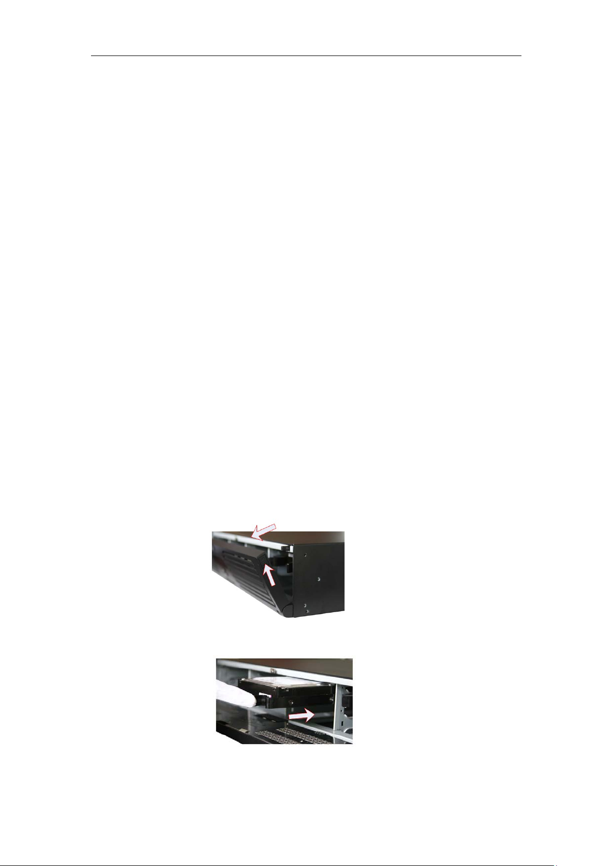
Hard Disk Installation
Before installing a hard disk drive (HDD), please make sure the power is disconnected from the NVR. A factory
recommended HDD should be used for this installation.
Tools Required: Screwdriver.
1. Use the screws to install HDD to its mounting bracket.
2. Press the latches on both sides of the front panel of NVR chassis to open it.
3. Inser the HDD bracket to the chassis along the slot unitl it has fully seated into position.
4. Close the front panel of the NVR chassis.
1
Page 3
DS-9500 Series NVR Quick Operation Guide
en network connection is functioning
and USB Hard Disk Drive (HDD).
recording & network connection.
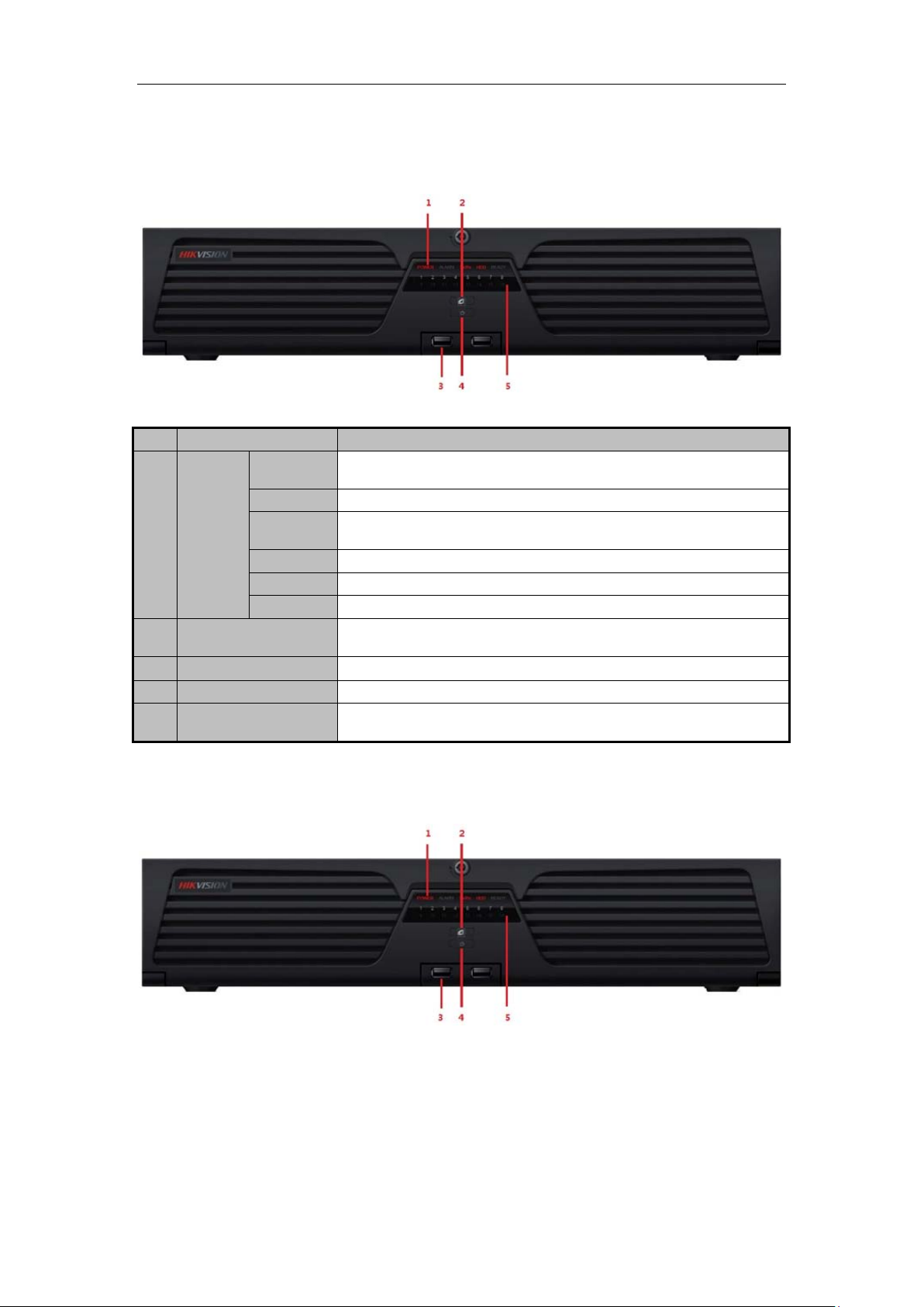
Front Panel
DS-9508NI-S/R Front Panel
No.
1
2
Status
LED
Indicators
Name
USB Ports Universal Serial Bus (USB) ports for additional devices such as USB mouse
Power
Alarm Alarm indicator turns red when a sensor alarm is detected.
TX/RX
HDD HDD indicator blinks red when data is being read from or written to HDD.
Ready Ready indicator turns blue when NVR is functioning properly.
Backup Backup indicator blinks blue when data is being backup.
Turning red indicates power supply but without system running, turning blue
indicates power supply and system running.
TX/RX indictor blinks blue wh
properly.
Description
3
4
5
Power Button
Backup Button
Channel Status Indicators Blue indicates recording, red indicates network connection, purple indicates
Powers NVR on/off.
Backup video files.
DS-9516NI-S/R Front Panel:
2
Page 4
DS-9500 Series NVR Quick Operation Guide
indicates power supply and system running.
TX/RX indictor blinks blue when network connection is functioning
No.
1
2
3
4
5
Name
Status
LED
Indicators
Backup Button
USB Ports Universal Serial Bus (USB) ports for additional devices such as USB mouse
Power Button
Channel Status
Indicators
Power
Alarm Alarm indicator turns red when a sensor alarm is detected.
TX/RX
HDD HDD indicator blinks red when data is being read from or written to HDD.
Ready Ready indicator turns blue when NVR is functioning properly.
Backup Backup indicator blinks blue when data is being backup.
Turning red indicates power supply but without system running, turning blue
properly.
Backup video files.
and USB Hard Disk Drive (HDD).
Powers NVR on/off.
Blue indicates recording, red indicates network connection, purple indicates
recording & network connection.
Description
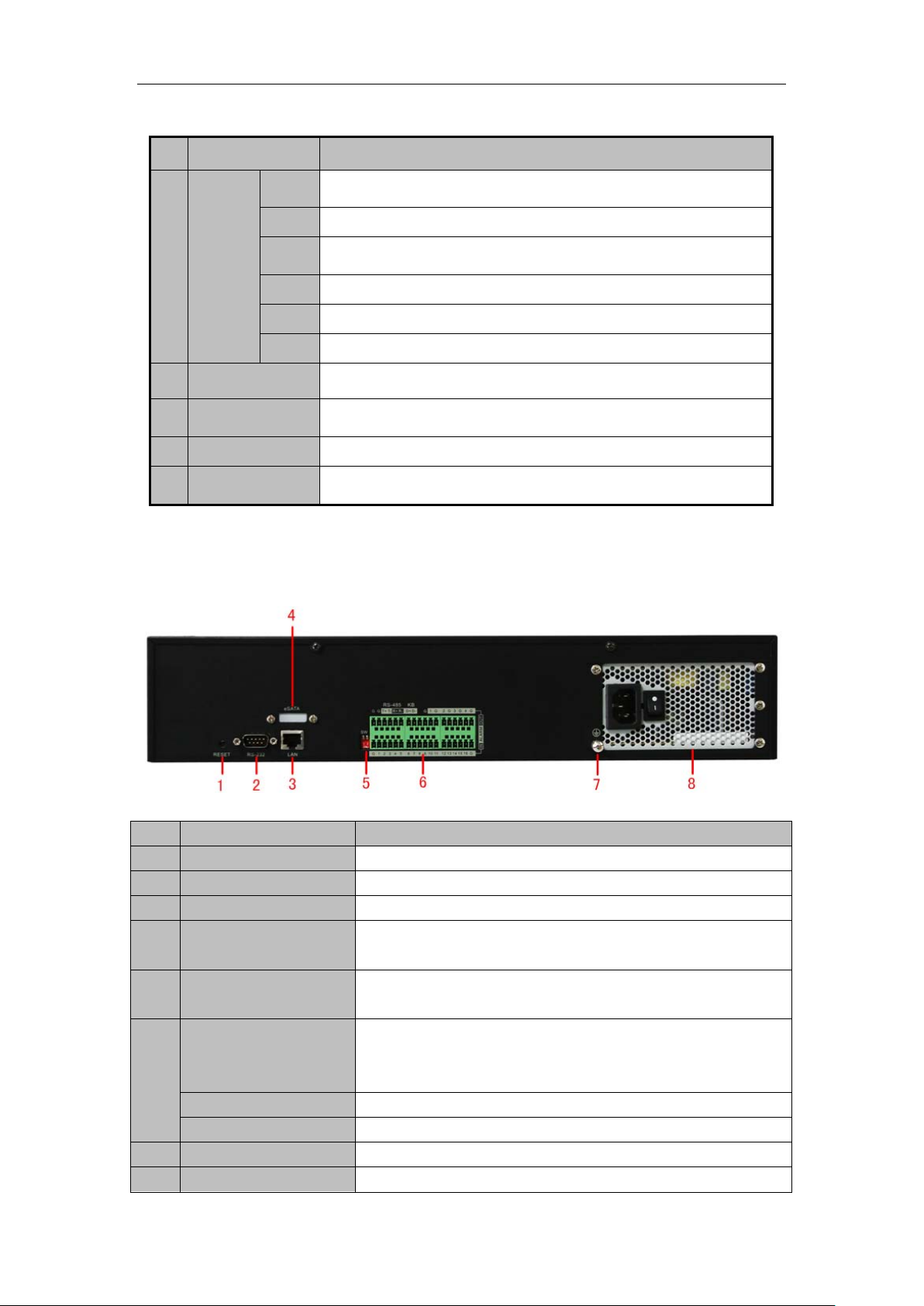
Rear Panel
DS-9508NI-S/R Rear Panel:
No. Item Description
1 RESET Press and hold it for 10 seconds to reset all parameters to factory defaults.
2 RS-232 Connect to RS-232 devices.
3 LAN 10/100/1000Mbps Self-adaptive UTP Ethernet interface.
4 eSATA (optional) Backup/extended storage interface, connect to external SATA disk,
CD-RW, disk array, etc.
5 RS-485 Matching
Resistor Switch (SW)
7 GND Grounding
8 POWER 220VAC power supply
RS-485
6
ALARM IN 16 relay alarm inputs
ALARM OUT 4 relay alarm outputs
Connection of 120-ohm terminator for RS-485 bus. ON=connected;
OFF=disconnected.
Connect to RS-485 devices, e.g., P/T receiver, etc. Use the T+ and T-
terminals of RS-485 interface to connect to the R+ and R- terminals of the
receiver.
3
Page 5
DS-9500 Series NVR Quick Operation Guide
DS-9516NI-S/R Rear Panel:
No. Item Description
1 RESET Press and hold it for 10 seconds to reset all parameters to factory defaults
2 RS-232 Connect to RS-232 devices
3 LAN 10/100/1000Mbps Self-adaptive UTP Ethernet interface.
4 eSATA (optional) Backup/extended storage interface, connect to external SATA disk,
CD-RW, disk array, etc.
5 RS-485 Matching
Resistor Switch (SW)
7 GND Grounding
8 POWER 220VAC power supply
RS-485
6
ALARM IN 16 relay alarm inputs
ALARM OUT 4 relay alarm outputs
Note: Currently the RS-485 interface of DS-9500 NVR is reserved for future use.
Connection of 120-ohm terminator for RS-485 bus. ON=connected;
OFF=disconnected.
Connect to RS-485 devices, e.g., P/T receiver, etc. Use the T+ and T-
terminals of RS-485 interface to connect to the R+ and R- terminals of the
receiver.
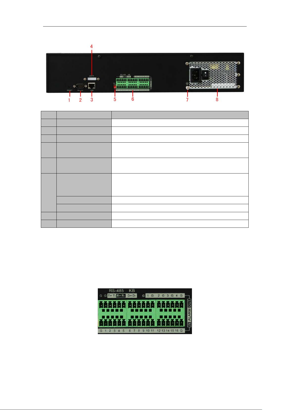
Connections
Connecting to Alarm Input/Output Device
The alarm input/output interface of the NVR is shown below:
The alarm input is an open/close relay. If the input is not an open/closed relay, follow the connection diagram below:
4
Page 6
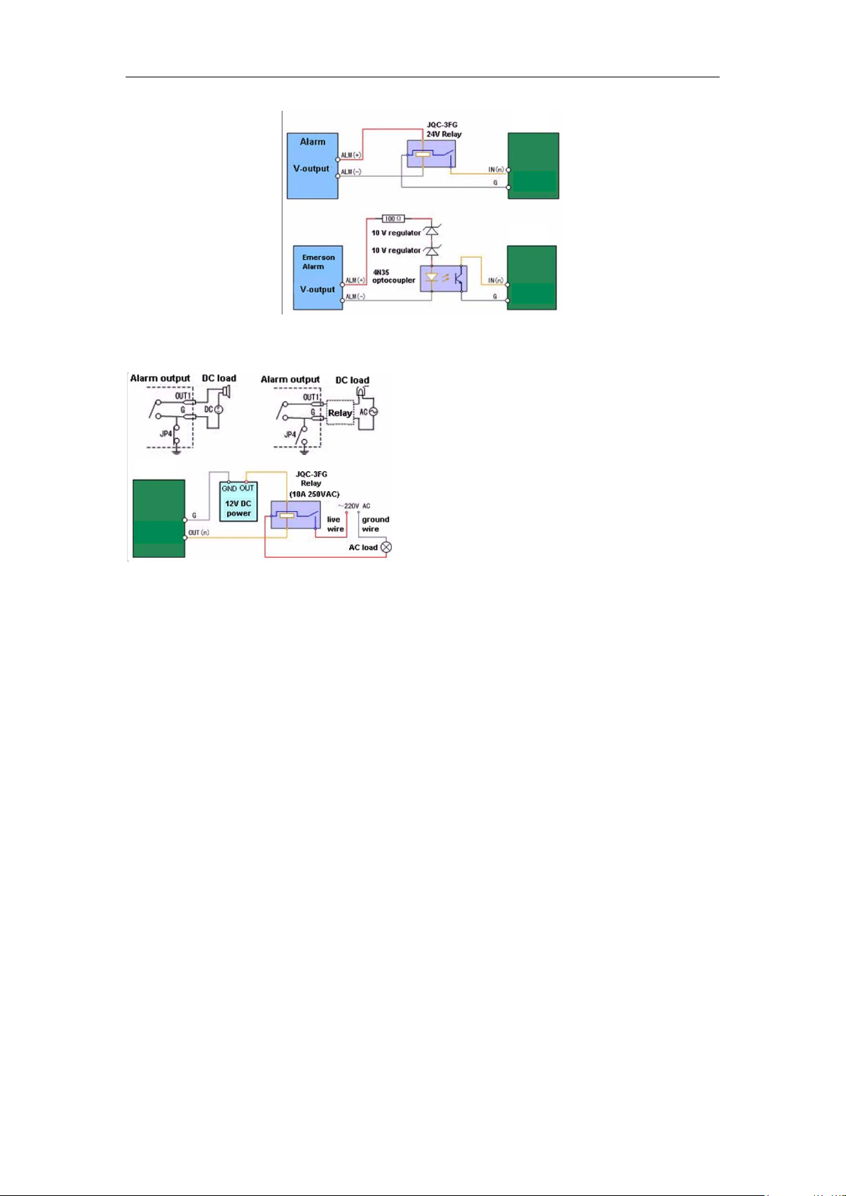
DS-9500 Series NVR Quick Operation Guide
Relay alarm
input
Relay alarm
input
NVR
NVR
Relay alarm
output
NVR
To connect to an AC/DC load, use the following diagram:
For DC load, JP4 can be used within the limit of 12V/1A safely. If the interface is connected to an AC load, JP4 should be left
open. Use an external relay for safety (as shown in the figure above).
Note: An external relay is needed to prevent electric shock when connecting to an AC load.
Alarm Connections:
The device provides the green mating plugs for alarm input and alarm output connectors. Operate the following steps:
1. Remove the green mating plug from the ALARM IN or ALARM OUT connector.
2. Use the screwdriver to loosen the screw in the plug and then place the wire to the top of screw and finally tighten the screw
to secure the wires.
3. Insert the plug to its mating slot.
5
Page 7

DS-9500 Series NVR Quick Operation Guide
Specifications
DS-9500NI-S:
Model DS-9508NI-S DS-9516NI-S
Video/Audio input IP video input
Hard disk
External interface
Others
Type 8 SATA interfaces
Capacity Each interface supports up to 2TB capacity
Network
interface
Serial interface
USB interface 2, USB 2.0
Alarm in 16
Alarm out 4
Power
supply
Consumption ≤ 20 W (without hard disk or DVD-R/W)
Working
temperature
Working
humidity
Chassis 19’’ standard 2U chassis
Dimensions
(W × D × H)
8-ch 4CIF/4-ch 720P/2-ch
UXGA Real Time, or 4-ch
UXGA/2-ch 5 Megapixel not
Real Time
1,RJ-45, 10/100/1000 Mbps adaptive Ethernet interface
1 RS-232 interface (for parameters configuration, maintenance ,
transparent channel);
1 RS-485 interface (for PTZ control);
1 RS-485 keyboard interface (for special keyboard control)
100 ~ 240VAC, 6.3A, 50 ~ 60Hz
-10℃ ~ +55℃
10% ~ 90%
450 × 450 × 95 mm
16-ch 4CIF/8-ch 720P/4-ch UXGA
Real Time, or 8-ch
UXGA/4-ch 5 Megapixel not Real
Time
Weight ≤ 8 kg ( without hard disk or DVD-R/W )
6
Page 8

DS-9500 Series NVR Quick Operation Guide
mber of
DS-9500NI-R:
Model DS-9508NI-R DS-9516NI-R
Video/Audio input IP video input
Hard disk
Disk array
External interface
Type 8 SATA interfaces
Capacity Each interface supports up to 2TB capacity
Array type RAID 0, RAID 1, RAID 5, RAID 10
Number of array 8
Nu
virtual disk
Network
interface
Serial interface
USB interface 2, USB 2.0
Alarm in 16
Alarm out 4
8-ch 4CIF/4-ch 720P/2-ch
UXGA Real Time, or 4-ch
UXGA/2-ch 5 Megapixel not
Real Time
8
1,RJ-45, 10/100/1000 Mbps adaptive Ethernet interface
1 RS-232 interface (for parameters configuration, maintenance ,
transparent channel);
1 RS-485 interface (for PTZ control);
1 RS-485 keyboard interface (for special keyboard control)
16-ch 4CIF/8-ch 720P/4-ch UXGA
Real Time, or 8-ch
UXGA/4-ch 5 Megapixel not Real
Time
Others
Power
supply
Consumption ≤ 20 W (without hard disk or DVD-R/W)
Working
temperature
Working
humidity
Chassis 19’’ standard 2U chassis
Dimensions
(W × D × H)
Weight ≤ 8 kg ( without hard disk or DVD-R/W )
100 ~ 240 VAC, 6.3 A, 50 ~ 60 Hz
-10℃ ~ +55℃
10% ~ 90%
450 × 450 × 95 mm
7
Page 9

DS-9500 Series NVR Quick Operation Guide
HDD Storage Calculation Chart
The following chart shows an estimation of storage space used based on recording at one channel for an hour at a
fixed bit rate.
Bit Rate Storage Used
96K 42M
128K 56M
160K 70M
192K 84M
224K 98M
256K 112M
320K 140M
384K 168M
448K 196M
512K 225M
640K 281M
768K 337M
896K 393M
1024K 450M
1280K 562M
1536K 675M
1792K 787M
2048K 900M
Note: Please note that supplied values for storage space used is just for reference. Storage space used is
estimated by formulas and may have some deviation from actual value.
8
Page 10

DS-9500 Series NVR Quick Operation Guide
Basic Operation
Starting and Shutting Down Your NVR
Startup
Apply power to the unit and the POWER LED indicator on the front panel will light in green, which indicates the
unit is powered on.
Note: DS-9500 series NVR do not provide local output, when the POWER and LINK LED indicators light
normally, it indicates the unit has been successfully started and connected to network.
Shutdown
Unplug the power cord to shut down the unit. It is not recommended to directly shut down the unit when it is in
recording.
Note: It is recommended that an Uninterruptible Power Supply (UPS) be used so as to ensure the unit to work
with high stability and security.
Access to DS-9500 by Client Software
Click “Start””All Programs”“iVMS-4000(v2.0)” to start the client software. After successful login, user can
enter the following main interface of the client software.
If the SADP software has been installed on PC, user can use it to automatically search and add the onl ine devices
within the same local area network. Click Online Devices button on the Add Device interface, a nd the sy stem wil l
automatically search the online devices.
The devices found will be listed on the panel with detail information.
9
Page 11

DS-9500 Series NVR Quick Operation Guide
Select a device from the list and then click the Select Device button to add the device.
User can also click the Modify button to modify the subnet mask, IP address and device port of the device, and
then input the user name and password for login, and finally click Save to complete the modification.
Note: If it is required to modify the default gateway, enter the SetupRemote SettingsNetwork
ParametersNetwork Settings to change the settings.
Note: For detailed instructions, please refer to the User Manual of iVMS 4000 V2.0.
Access to DS-9500 by IE Browser
Login and Exit
Open IE browser, input the IP address of DS-9500 (e.g.,172.9.1.76) and then click Enter. The system will remind
you to install the ActiveX control. Click and install the ActiveX control.
The system then will display the login interface as shown in the following figure:
10
Page 12

DS-9500 Series NVR Quick Operation Guide
On the top right corner, language is selectable between Chinese and English.
Input the correct user name, password and port, click Login to enter preview interface, or it will pop up an error
box. The default user name is admin, password is 12345, and port is 8000.
After login, the following interface will appear:
User can click Exit to log off and return to the login interface.
Add Device
Click ConfigRemote Config to enter IP camera configuration menu.
11
Page 13

DS-9500 Series NVR Quick Operation Guide
Refer to the following table for the number of IP cameras which can be added at different resolution:
Model Name
DS-9508NI-S/R
DS-9516NI-S/R
Up to 8-ch 4CIF or 4-ch 720P or 2-ch UXGA IP cameras
Up to 16-ch 4CIF or 8-ch 720P or 4-ch UXGA IP cameras
IP camera connections
Quick Adding of IP Camera
This function enables you to add an IP camera quickly. When there are supported IP cameras in the same network
segment of a LAN with NVR, you may add it with default user name, password and port number.
Note: Before applying Quick Add function, please make sure that IP camera is compatible with NVR and the
default user name, password, port number are not changed.
Select a Channel No., and then click
and the online IP cameras will be listed as figure shown below:
12
Page 14

DS-9500 Series NVR Quick Operation Guide
Select the IP camera from the list to be added and then clic k OK to finish the adding.
Single Adding of IP Camera
This function enables you to add a single IP camera quickly. When there are supported IP cameras in the same
network segment of a LAN with NVR, you may add it in one button with default user name, password and port
number.
Note: Before applying Single Add function, please make sure that IP camera is compatible with NVR and the
default user name, password, port number are not changed.
First, select a Channel No., and then click
below:
and the online IP cameras will be listed as figure shown
Select one IP camera from the list and click to finish the adding.
Then you can change IP address, sub mask or user name, password in the menu on the right, and click Modify to
confirm.
Manual Adding of IP Camera
First select a Channel No. to enable IP camera Config menu shown on the right.
Input the IP address, port, user name and password, click Modify to finish adding an IP camera that will be listed
in the IP Camera Information area.
13
Page 15

DS-9500 Series NVR Quick Operation Guide
Preview
After login, the preview interface will display:
When live preview, the windows division can be selected by click the button on play control area. It can support 1
and 4 windows division. The change between different windows division modes will not stop the current preview;
and the window still can be operated.
Preview by channel:
After having selected window division mode, click one window, and click
current channel. If preview successful, the icon will become
.
on channel list to preview the
14
Page 16

DS-9500 Series NVR Quick Operation Guide
Preview by device:
Click the device node on the list, then multiple channels will start to be dis played synchronously on the selected
window divisions. When the 1-window division mode is selected, click
to the previous window for preview.
click
to switch to the next window, or
Recording
Start/Stop Recording
Click ConfigLocal Config to enter local configuration menu where user can change the directory of saving
recording file and the size of file packing.
15
Page 17

DS-9500 Series NVR Quick Operation Guide
Note: If the free space in the defined disk is less than 500M, the web server will stop recording automatically.
Click
failed”.
button on playlist to start recording of this channel, and if the icon is not , it will prompt “Recording
Click
When multiple channels are under previewing, user may click
stop all channel recording.
icon again to stop recording, and the saving file folder will pop up automatically.
to start all channel recording, or click to
Note: Stop previewing will also stop recording of the current channel.
Schedule Recording Settings
Click ConfigRemote ConfigParameters Configuration to e nter the remote settings interface of the
NVR.
Step1: Click Schedule Record to enter the schedule record settings interface. Enable Schedule Recording.
Step 2: Set recording time and type.
Click Settings button of Record Time to enter record time settings interface.
16
Page 18

DS-9500 Series NVR Quick Operation Guide
Select one day in a week, and select All Day Recording if necessary. You may also set period recording by
disable All Day Recording; there are 8 time periods in one day. Then you can select schedule recording from the
drop-down menu beside the periods. Then you may also select copy the settings to whole week or to one day.
Note: Please make sure each time period is not overlapped with each other.
Playback
Click Playback button to enter the playback interface. Select the channel for playback and search the record files
by date from the right column. If corresponding record file is found, the time bar will be displayed at the window
bottom. Click Play to start playing the selected record file. The selected record files can be downloaded by
clicking the button. Refer to the following figure:
During the playback of record files, user may click the
can be used for capturing pictures and the button is video clipping. User can also click the button to
open/close audio during playback.
button to enter the full screen mode. The button
17
 Loading...