

Page 1

DS-90xxHUHI-F8/N
Digital Video Recorder
User Manual
041717NA
Page 2

COPYRIGHT © 2017 Hangzhou Hikvision Digital Technology Co., Ltd. ALL RIGHTS RESERVED.
Any and all information, including, among others, wordings, pictures, graphs are the properties of Hangzhou Hikvision Digital Technology Co., Ltd. or its subsidiaries
(hereinafter referred to be “Hikvision”). This user manual (hereinafter referred to be “the Manual”) cannot be reproduced, changed, translated, or distributed, partially
or wholly, by any means, without the prior written permission of Hikvision. Unless otherwise stipulated, Hikvision does not make any warranties, guarantees or
representations, express or implied, regarding to the Manual.
About this Manual
This Manual is applicable to TurboHD Digital Video Recorder (DVR).
The screen shots in this manual are for illustative purposes only; your screen(s) may differ.
The Manual includes instructions for using and managing the product. Pictures, charts, images and all other information hereinafter are for description and
explanation only. The information contained in the Manual is subject to change, without notice, due to firmware updates or other reasons. Please find the latest
version in the company website (http://overseas.hikvision.com/en/).
Please use this user manual under the guidance of professionals.
Trademarks Acknowledgement
properties of their respective owners.
Legal Disclaimer
TO THE MAXIMUM EXTENT PERMITTED BY APPLICABLE LAW, THE PRODUCT DESCRIBED, WITH ITS HARDWARE, SOFTWARE AND FIRMWARE, IS
PROVIDED “AS IS”, WITH ALL FAULTS AND ERRORS, AND HIKVISION MAKES NO WARRANTIES, EXPRESS OR IMPLIED, INCLUDING WITHOUT
LIMITATION, MERCHANTABILITY, SATISFACTORY QUALITY, FITNESS FOR A PARTICULAR PURPOSE, AND NON-INFRINGEMENT OF THIRD PARTY. IN
NO EVENT WILL HIKVISION, ITS DIRECTORS, OFFICERS, EMPLOYEES, OR AGENTS BE LIABLE TO YOU FOR ANY SPECIAL, CONSEQUENTIAL,
INCIDENTAL, OR INDIRECT DAMAGES, INCLUDING, AMONG OTHERS, DAMAGES FOR LOSS OF BUSINESS PROFITS, BUSINESS INTERRUPTION, OR
LOSS OF DATA OR DOCUMENTATION, IN CONNECTION WITH THE USE OF THIS PRODUCT, EVEN IF HIKVISION HAS BEEN ADVISED OF THE
POSSIBILITY OF SUCH DAMAGES.
and other Hikvision’s trademarks and logos are the properties of Hikvision in various jurisdictions. Other trademarks and logos mentioned below are the
REGARDING TO THE PRODUCT WITH INTERNET ACCESS, THE USE OF PRODUCT SHALL BE WHOLLY AT YOUR OWN RISKS. HIKVISION SHALL NOT
TAKE ANY RESPONSIBILITES FOR ABNORMAL OPERATION, PRIVACY LEAKAGE OR OTHER DAMAGES RESULTING FROM CYBER ATTACK, HACKER
ATTACK, VIRUS INSPECTION, OR OTHER INTERNET SECURITY RISKS; HOWEVER, HIKVISION WILL PROVIDE TIMELY TECHNICAL SUPPORTS IF
REQUIRED.
SURVEILLANCE LAWS VARY BY JURISDICTION. PLEASE CHECK ALL RELEVANT LAWS IN YOUR JURISDICTION BEFORE USING THIS PRODUCT IN
ORDER TO ENSURE THAT YOUR USE CONFORMS THE APPLICABLE LAW. HIKVISION SHALL NOT BE LIABLE IN THE EVENT THAT THIS PRODUCT IS
USED WITH ILLEGITIMATE PURPOSES.
IN THE EVENT OF ANY CONFLICTS BETWEEN THIS MANUAL AND THE APPLICABLE LAW, THE LATER PREVAILS.
Regulatory Information
FCC Information
Please take attention that changes or modification not expressly approved by the party responsible for compliance could void the user’s authority to operate the
equipment.
FCC Compliance
This equipment has been tested and found to comply with the limits for a Class A digital device, pursuant to part 15 of the FCC Rules. These limits are designed to
provide reasonable protection against harmful interference when the equipment is operated in a commercial environment. This equipment generates, uses, and can
radiate radio frequency energy and, if not installed and used in accordance with the instruction manual, may cause harmful interference to radio communications.
Operation of this equipment in a residential area is likely to cause harmful interference in which case the user will be required to correct the interference at his own
expense.
FCC Conditions
This device complies with part 15 of the FCC Rules. Operation is subject to the following two conditions:
1. This device may not cause harmful interference.
2. This device must accept any interference received, including interference that may cause undesired operation.
EU Conformity Statement
This product and - if applicable - the supplied accessories too are marked with "CE" and comply therefore with the applicable harmonized European
standards listed under the EMC Directive 2014/30/EU, the LVD Directive 2014/35/EU, the RoHS Directive 2011/65/EU.
2012/19/EU (WEEE directive): Products marked with this symbol cannot be disposed of as unsorted municipal waste in the European Union. For proper
recycling, return this product to your local supplier upon the purchase of equivalent new equipment, or dispose of it at designated collection points. For
more information see: www.recyclethis.info
2006/66/EC (battery directive): This product contains a battery that cannot be disposed of as unsorted municipal waste in the European Union. See the
product documentation for specific battery information. The battery is marked with this symbol, which may include lettering to indicate cadmium (Cd), lead
(Pb), or mercury (Hg). For proper recycling, return battery to your supplier or a designated collection point. For more information see www.recyclethis.info
Industry Canada ICES-003 Compliance
This device meets the CAN ICES-3 (A)/NMB-3(A) standards requirements.
UM DS-90xxHUHI-F8/N User Manual 041717NA 1
Page 3
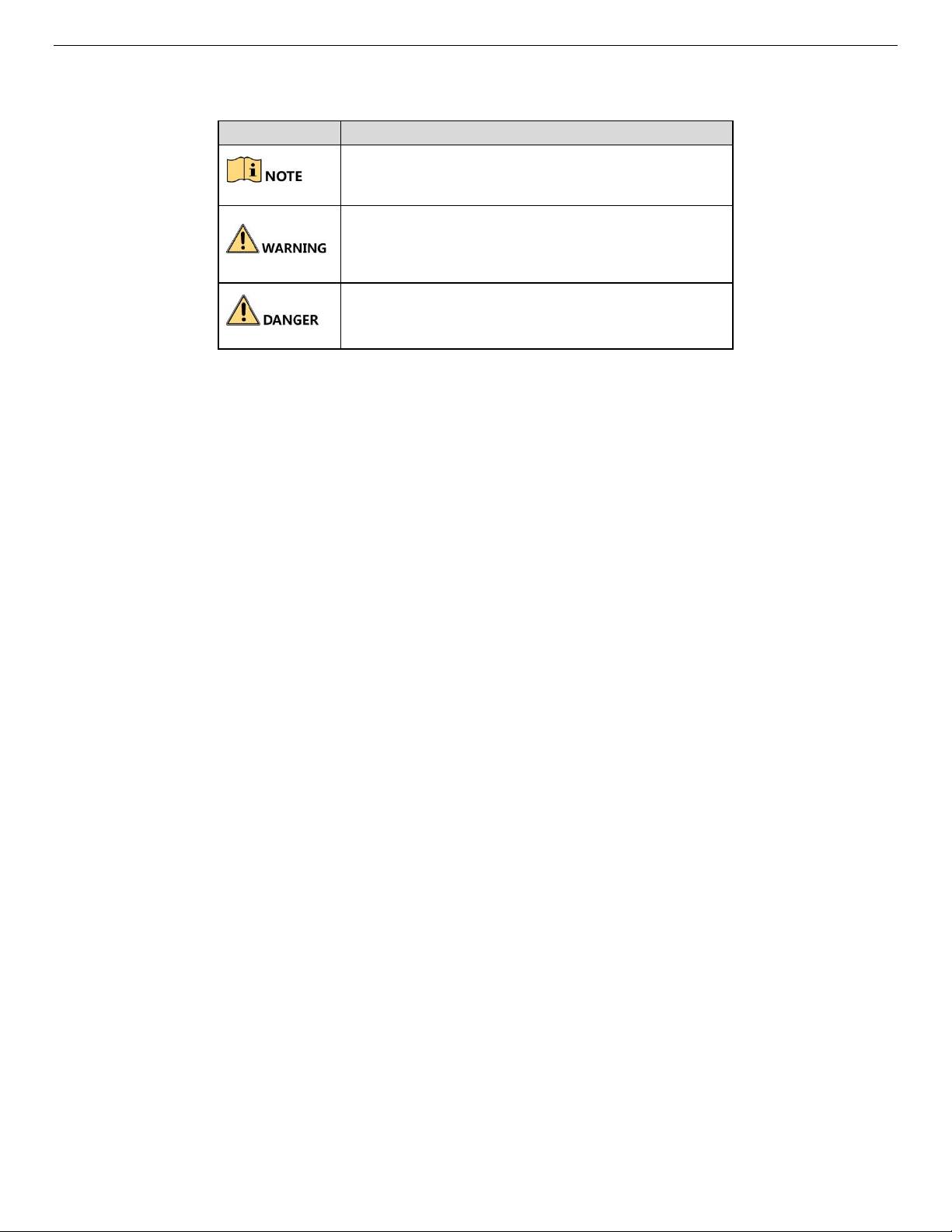
Symbol
Description
Symbol Conventions
The symbols that may be found in this document are defined as follows.
Provides additional information to emphasize or
supplement important points of the main text.
Indicates a potentially hazardous situation, which if not
avoided, could result in equipment damage, data loss,
performance degradation, or unexpected results.
Indicates a hazard with a high level of risk, which if not
avoided, will result in death or serious injury.
Safety Instructions
Proper configuration of all passwords and other security settings is the responsibility of the installer and/or end-user.
In the use of the product, you must be in strict compliance with the electrical safety regulations of the nation and region. Please refer to technical specifications for
detailed information.
Input voltage should meet both the SELV (Safety Extra Low Voltage) and the Limited Power Source with 100 to 240 VAC or 12 VDC according to the IEC60950-1
standard. Please refer to technical specifications for detailed information.
Do not connect several devices to one power adapter as adapter overload may cause over-heating or a fire hazard.
Please make sure that the plug is firmly connected to the power socket.
If smoke, odor or noise rise from the device, turn off the power at once and unplug the power cable, and then please contact the service center.
Preventive and Cautionary Guidelines
Before connecting and operating your device, please be advised of the following:
Ensure unit is installed in a well-ventilated, dust-free environment.
Unit is designed for indoor use only.
Keep all liquids away from the device.
Ensure environmental conditions meet factory specifications.
Ensure unit is properly secured to a rack or shelf. Major shocks or jolts to the unit as a result of dropping it may cause damage to the sensitive electronics within
the unit.
Use the device in conjunction with an UPS if possible.
Power down the unit before connecting and disconnecting accessories and peripherals.
A factory recommended HDD should be used for this device.
Improper use or replacement of the battery may result in hazard of explosion. Replace with the same or equivalent type only. Dispose of used batteries according
to the instructions provided by the battery manufacturer.
UM DS-90xxHUHI-F8/N User Manual 041717NA 2
Page 4

Product Key Features
General
Connectable to HD-TVI and analog cameras
Supports Hikvision-C protocol for Up-the-Coax control of camera OSD and Hikvision PTZ cameras
Each channel supports dual-streams. Sub-stream supports up to WD1 resolution
The HUHI series main stream supports up to 3 MP resolution on all channels. IP cameras up to 8MP can be added. Analog channels can be disabled one by one
to allow for additional IP cameras
If the 3 MP camera is connected to the channel that supports up to 1080p signal input, it will switch to 1080p signal input. When the 3 MP signal is switched to
1080p signal, the PAL will be switched to 1080p/25 Hz, and the NTSC will be switched to 1080p/30 Hz
Independent configuration for each channel, including resolution, frame rate, bit rate, image quality, etc.
Encoding for both video stream and video & audio stream; audio and video synchronization during composite stream encoding
One-key enable or disable H.264+
Supports configuring night to day sensitivity, day to night sensitivity and IR light brightness for the connected analog cameras supporting these parameters
Watermark technology
Local Monitoring
1/4/6/8/9/16 screen live view is supported, and the display sequence of screens is adjustable
Live view screen can be switched in group and manual switch and automatic cycle live view are also provided, the interval of automatic cycle can be adjusted
CVBS output only serves as the aux output or live view output
Quick setting menu is provided for live view
The selected live view channel can be shielded
Motion detection, video-tampering detection, video exception alarm, video loss alarm, and VCA alarm functions
Privacy mask
Support for over 60 PTZ protocols, including Pelco D, Pelco C, etc.; PTZ preset, patrol and pattern
Zooming in/out by clicking the mouse and PTZ tracing by dragging mouse
HDD Management
Each disk with a maximum of 6 TB storage
8 network disks (8 NAS disks, 8 IP SAN disks, or n NAS disks + m IP SAN disks (n + m ≤ 8)) can be connected
Remaining recording time of the HDD can be viewed
Supports cloud storage
S.M.A.R.T. and bad sector detection
HDD sleeping function
HDD property: redundancy, read-only, read/write (R/W)
HDD group management
HDD quota management; different capacity can be assigned to different channels.
Recording and Playback
Holiday recording schedule configuration
Cycle and non-cycle recording modes
Normal and event video encoding parameters
Multiple recording types: manual, continuous, alarm, motion, motion | alarm, motion & alarm, and Event
8 recording time periods with separated recording types
Main stream and sub-stream configurable for simultaneous recording
Pre-record and post-record for motion detection triggered recording, and pre-record time for schedule and manual recording
Searching record files and captured pictures by events (alarm input/motion detection)
Customization of tags, searching and playing back by tags
Locking and unlocking of record files
Local redundant recording and capture when configured with compatible NAS devices
When HD-TVI input is connected, the resolution will be overlaid on the bottom right corner of the live view for five seconds. When CVBS input is connected, the
information such as NTSC or PAL will be overlaid on the bottom right corner of the live view for 5 seconds.
Searching and playing back record files by camera number, recording type, start time, end time, etc.
Smart playback allows for faster searching
Main stream and sub-stream selectable for local/remote playback
Digital zooming during playback
Multi-channel reverse playback
Supports pause, fast forward, slow forward, skip forward, and skip backward when playing back, selecting playback time by dragging the mouse on the progress
bar
4/8/16-ch synchronous playback
Manual capture, continuous capture of video images and playback of captured pictures
UM DS-90xxHUHI-F8/N User Manual 041717NA 3
Page 5

Backup
Export data to a USB device (4/8/16 channel) and eSATA device (16 channel only)
Export video clips from playback
Management and maintenance of back-up devices
Alarms and Exceptions
Configurable arming time of alarm input/output
Alarm for video loss, motion detection, video tampering, abnormal signal, video input/recording resolution mismatch, illegal login, network disconnected, IP
confliction, record/capture exception, HDD error, HDD full, etc.
Alarm triggers full screen monitoring, audio alarm, notifying surveillance center, sending e-mail, and alarm output
Supports coaxial alarm
Automatic reboot when system watchdog detects problems in attempt to restore full function
Other Local Functions
Manual and automatic video quality diagnostics
Operable by mouse and remote control
Three-level user management; admin user can create multiple operating accounts and define their operating permission, which includes the permission to access
any channel
Completeness of operation, alarm, exceptions and log writing and searching
Manually triggering and clearing alarms
Importing and exporting of configuration file of devices
Getting camera type information automatically
Unlock pattern allows admin quick access to menu
Password can be shown in clear text by clicking icon
GUID file (password key) can be exported for easy password reset
Network Functions
One self-adaptive 10M/100M/1000M network interface (16 channel) or 1 self-adaptive 10M/100Mbps network interface (4/8 channel)
IPv6 is supported
TCP/IP protocol, PPPoE, DHCP, DNS, NTP, SADP, SMTP, NFS, iSCSI, UPnP™, and HTTPS are supported
Supports access by Hik Cloud P2P
TCP, UDP, and RTP for unicast
Auto/Manual port mapping by UPnP™
Remote search, playback, download, locking and unlocking the record files, and downloading files broken transfer auto resume
Remote parameters setup; remote import/export of device parameters
Remote viewing of the device status, system logs and alarm status
Remote keyboard operation
Remote HDD formatting and firmware upgrade
Remote system restart
Supports upgrading via remote FTP server
RS-485 transparent channel transmission
Alarm and exception information can be sent to the remote host
Remotely start/stop recording
Remotely start/stop alarm output
Remote PTZ control
Remote JPEG capture
Two-way audio and voice broadcasting
Output bandwidth limit configurable
Embedded WEB server
If DHCP is enabled, you can enable or disable DNS DHCP and edit the Preferred DNS Server and Alternate DNS Server
Development Scalability
SDK for Windows and Linux system
Source code of application software for demo
Development supports and training for application system
UM DS-90xxHUHI-F8/N User Manual 041717NA 4
Page 6

Table of Contents
1. Legend ............................................................................................................................................................................. 9
1.1. Front Panel .............................................................................................................................................................. 9
1.2. Rear Panel .............................................................................................................................................................. 9
1.3. Menu Tree ............................................................................................................................................................. 11
2. IR Remote Control Operations ..................................................................................................................................... 12
2.1. Troubleshooting the Remote Control ..................................................................................................................... 12
3. USB Mouse Operation .................................................................................................................................................. 13
3.1. Attach Mouse ........................................................................................................................................................ 13
3.2. Mouse Operation ................................................................................................................................................... 13
4. Soft Keyboard ................................................................................................................................................................ 14
5. Getting Started .............................................................................................................................................................. 14
5.1. Starting Up and Shutting Down the DVR ............................................................................................................... 14
5.1.1. Before Starting ........................................................................................................................................ 14
5.1.2. Starting the DVR ..................................................................................................................................... 14
5.1.3. Shutting Down the DVR .......................................................................................................................... 14
5.1.4. Rebooting the DVR ................................................................................................................................. 15
5.2. Activating the Device ............................................................................................................................................. 15
6. Using the Unlock Pattern for Login ............................................................................................................................. 18
6.1. Configuring the Unlock Pattern .............................................................................................................................. 18
6.2. Logging in via Unlock Pattern ................................................................................................................................ 19
7. Login and Logout .......................................................................................................................................................... 20
7.1. User Login ............................................................................................................................................................. 20
7.2. User Logout ........................................................................................................................................................... 23
8. Adding Cameras ............................................................................................................................................................ 23
8.1. Analog Cameras .................................................................................................................................................... 23
8.1.1. Adding Analog Cameras ......................................................................................................................... 23
8.1.2. Disabling Analog Cameras To Increase Number of IP Cameras ............................................................ 23
8.2. IP Cameras ........................................................................................................................................................... 24
8.2.1. Adding IP Cameras ................................................................................................................................. 24
8.2.2. Custom Adding IP Camera ..................................................................................................................... 26
8.2.3. Modify IP Camera Settings ..................................................................................................................... 26
8.2.4. Upgrade Camera Firmware..................................................................................................................... 27
8.2.5. Advanced Settings.................................................................................................................................... 27
8.3. Activating Camera ................................................................................................................................................. 29
9. Live View ........................................................................................................................................................................ 34
9.1. Live View Settings ................................................................................................................................................. 34
9.1.1. General ................................................................................................................................................... 34
UM DS-90xxHUHI-F8/N User Manual 041717NA 5
Page 7

9.1.2. View ........................................................................................................................................................ 35
9.1.3. Channel-Zero Encoding .......................................................................................................................... 35
9.1.4. Live View Icons ....................................................................................................................................... 36
9.2. Operations in Live View Mode ............................................................................................................................... 36
9.3. Using the Mouse in Live View ............................................................................................................................... 37
9.4. Quick Setting Toolbar in Live View Mode .............................................................................................................. 38
9.5. Adjusting Live View Settings ................................................................................................................................. 39
9.6. Manual Video Quality Diagnostics ......................................................................................................................... 41
10. PTZ Controls .................................................................................................................................................................. 42
10.1. Configuring PTZ Settings ...................................................................................................................................... 42
10.2. Setting PTZ Presets, Patrols, and Patterns ........................................................................................................... 43
10.2.1. Before Starting ........................................................................................................................................ 43
10.2.2. Customizing Presets ............................................................................................................................... 43
10.2.3. Calling Presets ....................................................................................................................................... 44
10.2.4. Customizing Patrols ................................................................................................................................ 45
10.2.5. Calling Patrols ........................................................................................................................................ 46
10.2.6. Customizing Patterns .............................................................................................................................. 47
10.2.7. Calling Patterns ...................................................................................................................................... 47
10.2.8. Customizing Linear Scan Limit ............................................................................................................... 48
10.2.9. Calling Linear Scan ................................................................................................................................. 49
10.2.10. One-Touch Park ..................................................................................................................................... 49
10.2.11. PTZ Control Panel .................................................................................................................................. 50
11. Recording Settings ....................................................................................................................................................... 52
11.1. Configuring Encoding Parameters ......................................................................................................................... 52
11.1.1. Before Starting ........................................................................................................................................ 52
11.2. Configuring Recording and Capture Schedule ...................................................................................................... 57
11.2.1. Set the Record Schedule ........................................................................................................................ 57
11.2.2. Draw the Schedule ................................................................................................................................. 59
11.3. Configuring Motion Detection Recording and Capture .......................................................................................... 60
11.4. Configuring Alarm Triggered Recording ................................................................................................................ 61
11.5. Configuring Event Recording ................................................................................................................................. 63
11.6. Configuring Manual Recording and Continous Capture ........................................................................................ 64
11.7. Configuring Holiday Recording .............................................................................................................................. 64
11.8. Configuring HDD Group ........................................................................................................................................ 66
11.9. Files Protection ...................................................................................................................................................... 67
11.9.1. Protect File by Locking the Record Files ................................................................................................ 67
11.9.2. Protect File by Setting HDD Property to Read-Only ............................................................................... 68
12. One-Key H.264+ Enable/Disable .................................................................................................................................. 69
12.1. One-Key H.264+ Enabling for All Cameras ........................................................................................................... 69
12.2. One-Key H.264+ Disabling for All Cameras .......................................................................................................... 69
13. Playback ........................................................................................................................................................................ 70
13.1. Playing Back Record Files ..................................................................................................................................... 70
13.1.1. Instant Playback by Channel .................................................................................................................. 70
13.1.2. Play Back by Time .................................................................................................................................. 71
13.2. Playback Interface ................................................................................................................................................. 72
13.3. Playing Back by Event Search .............................................................................................................................. 73
13.4. Playing Back by Tag .............................................................................................................................................. 75
13.4.1. Before Playing Back by Tag ................................................................................................................... 75
13.5. Playing Back by System Logs ............................................................................................................................... 77
UM DS-90xxHUHI-F8/N User Manual 041717NA 6
Page 8

13.6. Playing Back by Sub-Periods ................................................................................................................................ 78
13.7. Playing Back External Files ................................................................................................................................... 79
13.8. Auxiliary Playback Functions ................................................................................................................................. 79
13.8.1. Playing Back Frame-by-Frame ............................................................................................................... 79
13.8.2. Digital Zoom ........................................................................................................................................... 79
13.8.3. Reverse Playback of Multi-Channels ...................................................................................................... 80
14. Backing Up Record Files .............................................................................................................................................. 81
14.1. Before Starting ...................................................................................................................................................... 81
14.2. Backing Up by Normal Video/Picture Search ........................................................................................................ 81
14.2.1. Back Up Using USB Flash Drives and USB HDDs ................................................................................. 81
14.3. Backing Up by Event Search ................................................................................................................................. 83
14.4. Backing Up Video Clips ......................................................................................................................................... 84
14.5. Managing Backup Devices .................................................................................................................................... 84
15. Alarm Settings ............................................................................................................................................................... 85
15.1. Setting Motion Detection ....................................................................................................................................... 85
15.2. Setting Sensor Alarms ........................................................................................................................................... 87
15.3. Detecting Video Loss ............................................................................................................................................ 89
15.4. Detecting Video Tampering ................................................................................................................................... 91
15.5. Setting All-Day Video Quality Diagnostics ............................................................................................................. 92
15.6. Handling Exceptions .............................................................................................................................................. 93
15.7. Setting Alarm Response Actions ........................................................................................................................... 95
16. Network Settings ........................................................................................................................................................... 96
16.1. Configuring General Settings ................................................................................................................................ 96
16.2. Configuring Advanced Settings ............................................................................................................................. 97
16.2.1. Configuring PPPoE Settings ................................................................................................................... 97
16.2.2. Register a HIK-Connect P2P Cloud Service Account ............................................................................. 98
16.2.3. Enable Hik-Connect P2P on the NVR. .................................................................................................... 99
16.2.4. Add the NVR to the Hik-Connect Service ............................................................................................... 99
16.2.5. Accessing the NVR ............................................................................................................................... 100
16.2.6. Configuring NTP Server ........................................................................................................................ 100
16.2.7. Configuring NAT ................................................................................................................................... 101
16.2.8. Configuring More Settings .................................................................................................................... 102
16.2.9. Configuring HTTPS Port ....................................................................................................................... 104
16.2.10. Configuring E-Mail ................................................................................................................................ 105
16.2.11. Checking Network Traffic ...................................................................................................................... 107
16.3. Configuring Network Detection ............................................................................................................................ 107
16.3.1. Testing Network Delay and Packet Loss .............................................................................................. 107
16.3.2. Exporting Network Packet .................................................................................................................... 108
16.3.3. Checking Network Status ..................................................................................................................... 109
16.3.4. Checking Network Statistics ................................................................................................................. 110
17. HDD Management ....................................................................................................................................................... 111
17.1. Initializing HDDs .................................................................................................................................................. 111
17.2. Managing Network HDD ...................................................................................................................................... 112
17.3. Managing HDD Groups ....................................................................................................................................... 114
17.3.1. Setting HDD Groups ............................................................................................................................. 114
17.3.2. Setting HDD Property ........................................................................................................................... 116
17.4. Configuring Quota Mode ..................................................................................................................................... 117
17.5. Configuring Cloud Storage .................................................................................................................................. 118
17.6. Checking HDD Status ......................................................................................................................................... 120
UM DS-90xxHUHI-F8/N User Manual 041717NA 7
Page 9

17.6.1. Checking HDD Status in HDD Information Interface ............................................................................. 120
17.6.2. Checking HDD Status in System Information Interface ........................................................................ 120
17.7. Checking S.M.A.R.T. Information ........................................................................................................................ 121
17.8. Detecting Bad Sectors ......................................................................................................................................... 121
17.9. Configuring HDD Error Alarms ............................................................................................................................ 122
18. RAID Setup .................................................................................................................................................................. 124
18.1. Configuring Array ................................................................................................................................................ 124
18.1.1. Before You Start ................................................................................................................................... 124
18.1.2. Introduction ........................................................................................................................................... 124
18.1.3. Enable RAID ......................................................................................................................................... 125
18.1.4. One-Touch Configuration ..................................................................................................................... 125
18.1.5. Manually Creating Array ....................................................................................................................... 126
18.2. Rebuilding Array .................................................................................................................................................. 128
18.2.1. Before You Start ................................................................................................................................... 128
18.2.2. Automatically Rebuilding Array ............................................................................................................. 129
18.2.3. Manually Rebuilding Array .................................................................................................................... 129
18.3. Deleting Array ...................................................................................................................................................... 130
18.4. Checking and Editing Firmware ........................................................................................................................... 130
19. POS Configuration ...................................................................................................................................................... 132
19.1. Configuring POS Settings.................................................................................................................................... 132
19.2. Configuring Overlay Channel .............................................................................................................................. 137
19.3. Configuring POS Alarm ....................................................................................................................................... 137
20. Camera Settings .......................................................................................................................................................... 140
20.1. Configuring OSD Settings ................................................................................................................................... 140
20.2. Configuring Privacy Mask .................................................................................................................................... 141
20.3. Configuring Video Parameters ............................................................................................................................ 142
20.3.1. Configuring Image Settings .................................................................................................................. 142
20.3.2. Configuring Camera Parameters Settings ............................................................................................ 144
21. DVR Management and Maintenance .......................................................................................................................... 145
21.1. Viewing System Information ................................................................................................................................ 145
21.2. Searching Log Files ............................................................................................................................................. 145
21.3. Importing/Exporting Configuration Files............................................................................................................... 148
21.3.1. Purpose ................................................................................................................................................ 148
21.4. Upgrading System ............................................................................................................................................... 148
21.4.1. Upgrading by Local Backup Device ...................................................................................................... 148
21.4.2. Upgrading by FTP ................................................................................................................................. 149
21.5. Restoring Default Settings ................................................................................................................................... 150
21.6. Configuring General Settings .............................................................................................................................. 151
21.7. Configuring DST Settings .................................................................................................................................... 152
21.8. Configuring More Settings ................................................................................................................................... 152
21.9. Managing User Accounts .................................................................................................................................... 154
21.9.1. Adding a User ....................................................................................................................................... 154
21.9.2. Deleting a User ..................................................................................................................................... 158
21.9.3. Editing a User ....................................................................................................................................... 158
22. Appendix ...................................................................................................................................................................... 161
22.1. Glossary .............................................................................................................................................................. 161
22.2. Troubleshooting ................................................................................................................................................... 162
UM DS-90xxHUHI-F8/N User Manual 041717NA 8
Page 10
No. Item
Description
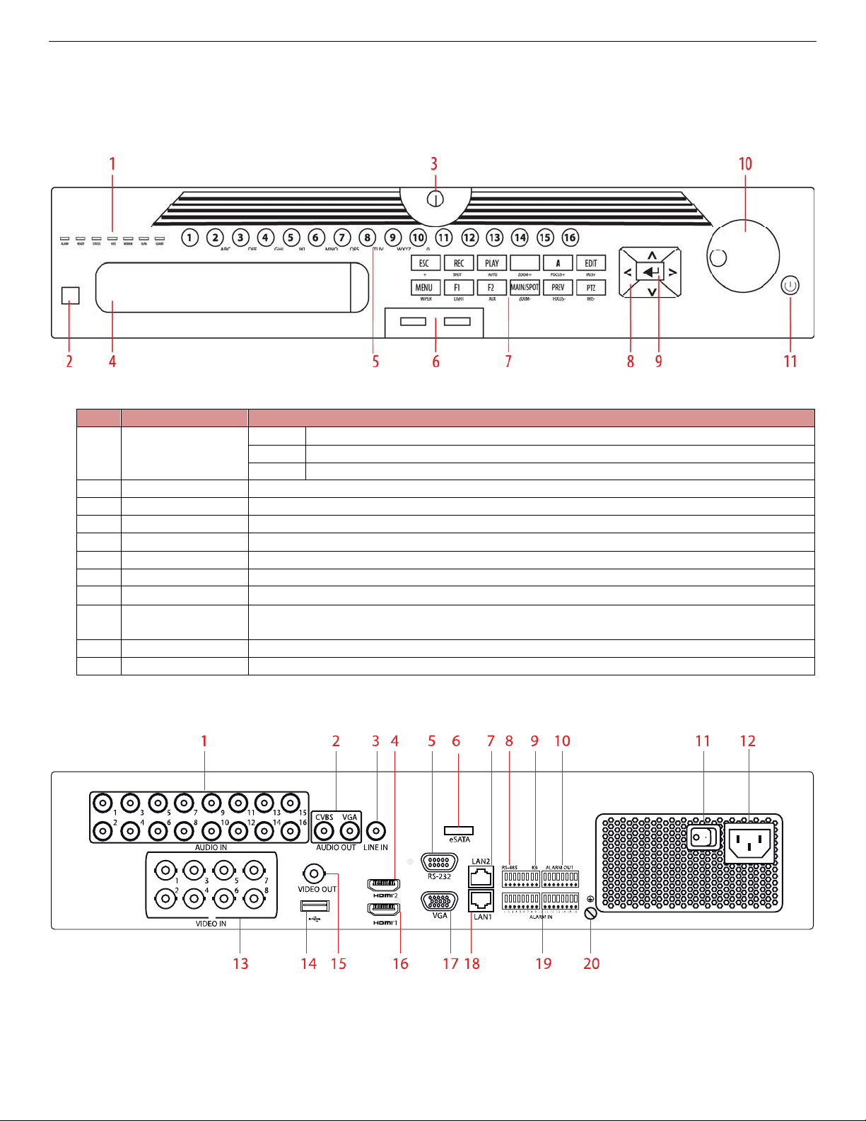
Ready
Flickers red when data is being read from or writt
en to HDD
HDD
Blinks red when data is being read from/written to HDD
Tx/Rx
Blinks blue when network connection is functioning properly
2.
IR Sensor
For remote control
3.
Front Panel Lock
Locks access to hard drives
4.
DVD Bay
For DVD drive
5.
Num
ber Buttons
To enter numbers
6.
USB Ports
Connects USB mouse or USB flash memory devices
7.
Function Buttons
Use to access device functions
8. Direction Buttons
Move up/down/left/right
Confirms menu selection. Ticks checkbox fields. In Playbac
k mode, plays or pauses
video. In Single Play mode, advances video a single frame.
10. Scroll Wheel
Use to scroll through selections
11. On/Off Power
Glows blue when device is on, red when powered off and in standby mode
1. Legend
1.1. Front Panel
Figure 1, DS-90xxHUHI-F8/N Front Panel
1. Status Indicators
9. Enter
1.2. Rear Panel
Figure 2, DS-9008HUHI-F8/N Rear Panel
UM DS-90xxHUHI-F8/N User Manual 041717NA 9
Page 11
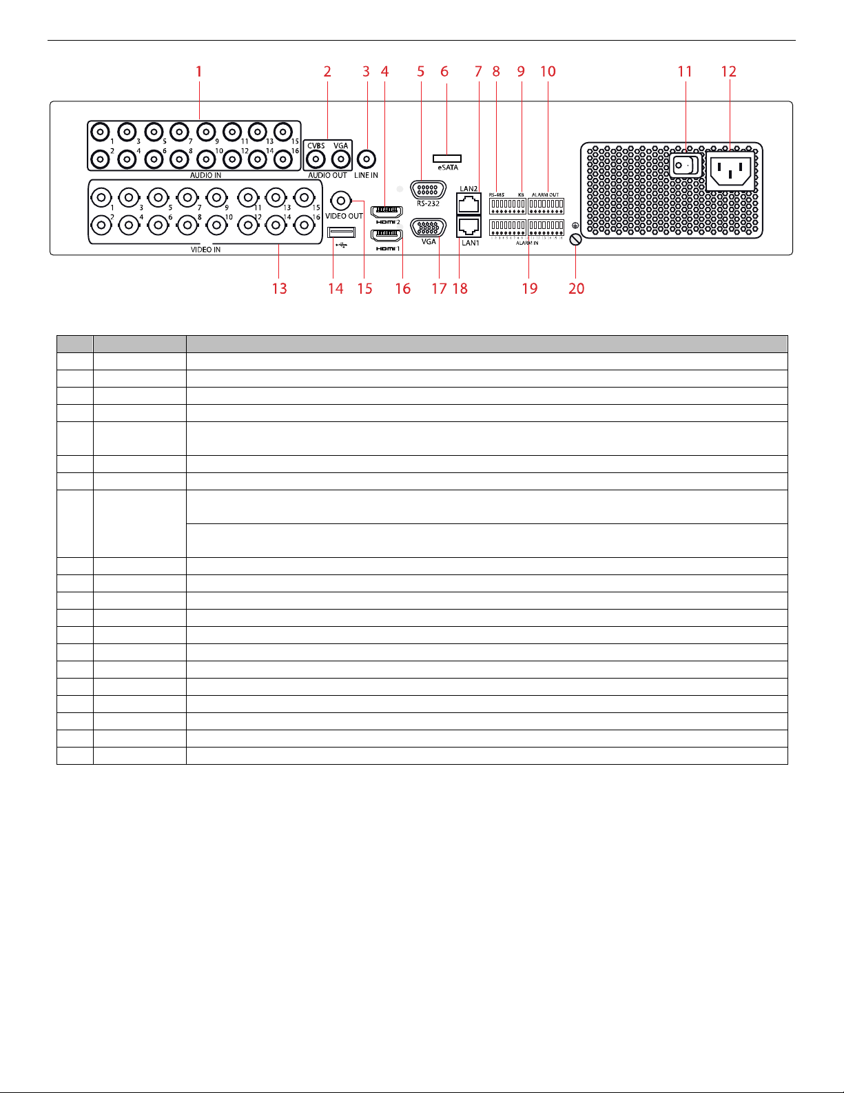
No. Item Description
1
Audio In
RCA connectors for audio input
2
Audio Out
RCA connectors for audio output
3
Line In
Mic input for two
-
way communication
4
HDMI2
HDMI video output connector
RS-232
Interfa
ce
6 eSATA
Connector to external eSATA drive
7
LAN2
Connector for LAN (Local Area Network)
Connector for RS
-
485 devices: T+ and T
- pins connect to R+ and R
- pins of PTZ receiver
respectively
D+, D
- pin connects t
o Ta, Tb pin of controller (for cascading devices, the first DVR’s D+, D
- pin
should be connected with the D+, D
- pin of the next DVR)
9 KB
Connector for keyboard
10 Alarm Out
Connector for alarm outputs
11
Power Switch
Switch for turning device on/off
12
Power Input
100 to 240 VAC power
13
Video In
BNC connectors for video input
14
USB Interface
Connect to USB mouse or USB flash memory devices
15
Video Out
BNC connector for video output
16
HDMI1
HDMI video output connector
17
VGA
DB-
15 connector
for VGA output to display local video output and menu
18
LAN1
Connector for LAN (Local Area Network)
19
Alarm In
Connectors for alarm inputs
20
Ground
Connect before powering up
Figure 3, DS-9016HUHI-F8/N Rear Panel
5
8 RS-485
Connector for RS-232 devices
NOTE: When HD-TVI input is connected, information including resolution and
frame rate (e.g., “720p25”) is overlaid on bottom right corner of live
view for five seconds for supported cameras.
When there is no video signal for the channel, the connectable video
signal type message will not be displayed on the screen.
When an unsupported signal input is connected, no video message is
displayed on the screen. Refer to the specifications for the supported
resolution of the analog signal input types.
UM DS-90xxHUHI-F8/N User Manual 041717NA 10
Page 12
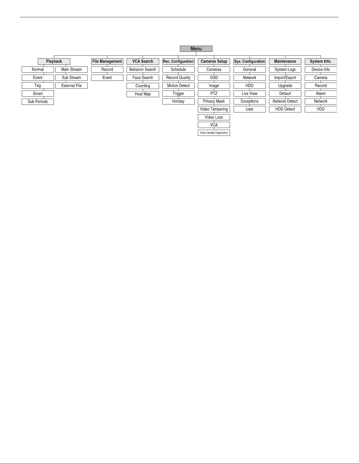
1.3. Menu Tree
UM DS-90xxHUHI-F8/N User Manual 041717NA 11
Page 13
No. Name
Description
Power on/off the device
Press the but
ton to return to the main menu after successful login
Press and hold button for 5 seconds
to turn off audible key beep
In PTZ
Control mode, MENU button w
ill start wiper (if applicable)
In Playback mode, show
s
/hide
s the control interface
Enter
s Manual Record setting menu
In PTZ control settings, press button and then
call a PTZ preset by
pressing n
umeric but
ton A
lso used to turn audio on/off in Playback mode
Navigate between diff
erent fields and items in menus
In Playback mode, the Up and Do
w
n button
s are speed up and
next and previous record files.
In Live View mode, buttons cycle through channels
In PTZ control mode, control
s movement of the PTZ camera
Confirm
s sele
ction in any of the menu modes
Can also be used to
tick
checkbox fields.
In Playback mode, play
s or pause
s the video
In single
-
frame Playback mode, advance video a single frame
5
PTZ Button
In Auto
-
switch mode,
stops
/start
s auto switch
6
DEV
Enables/Disables Remote Control
Switch
es to corres
ponding channel i
n Live View or PTZ Control
mode
Input
s numb
ers and characters in Edit mode
Switch
es between channels in the Playback mode
Goes back to the previous menu
Press
to Arm/disarm the device in Live View mode
E
nters
All-day Playback mode
Also auto scan
s in the PTZ Control menu
Switch
es between singl
e screen and multi
-
screen modes
In PTZ Control mode, adjust
s the focus in conjunction with the
A/FOCUS+ button
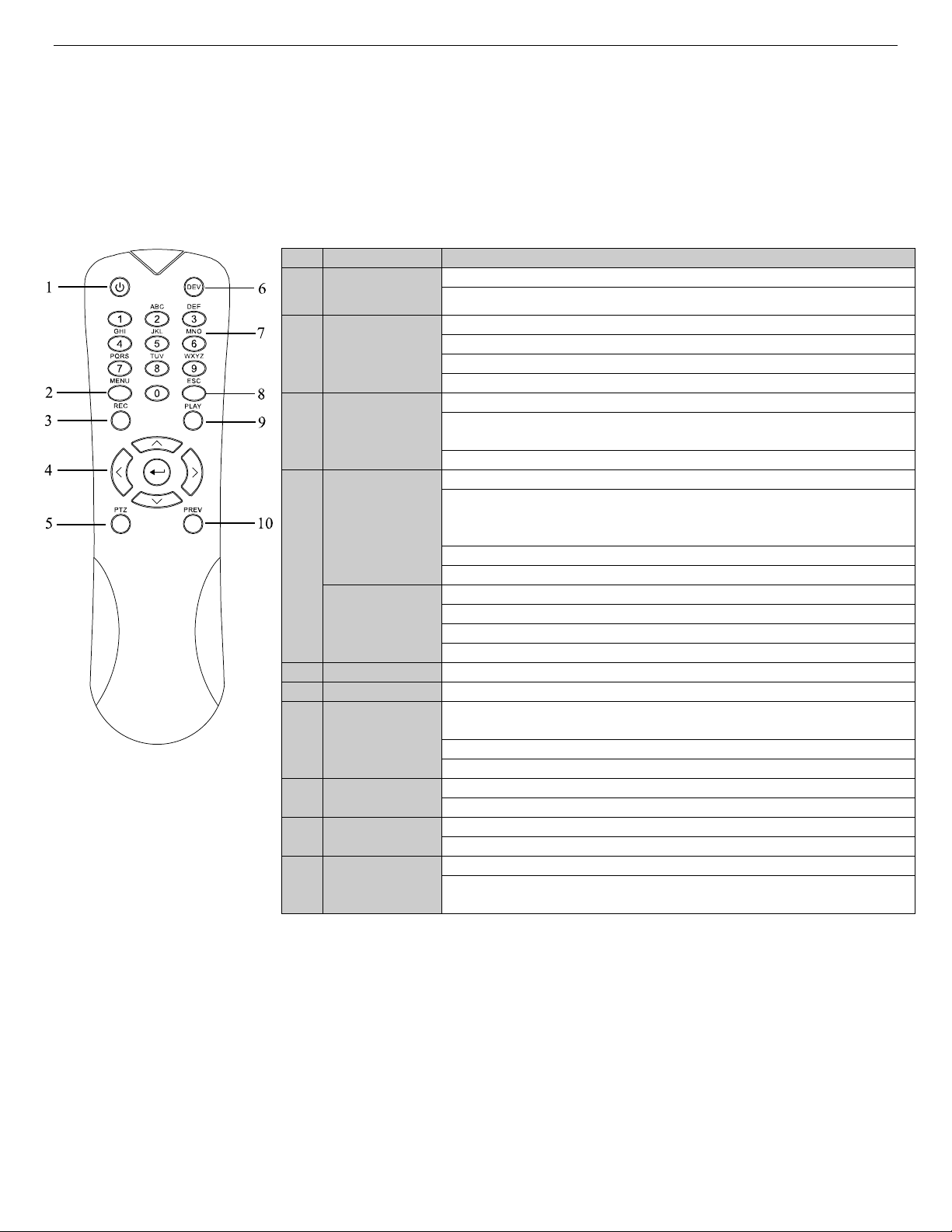
2. IR Remote Control Operations
The DVR may also be controlled with the included IR remote control. The keys on the remote control closely
resemble the ones found on the front panel.
NOTE: Batteries (2 × AAA) must be installed before operation.
Table 1.1 , Description of the IR Remote Control Buttons
1 POWER
2 MENU Button
3 REC Button
DIRECTION
Button
4
ENTER
Button
Alphanumeric
7
Buttons
Power on/off the device by pressing and holding button 5 seconds
slow down recorded video. Left and Right buttons will select the
8 ESC Button
9 PLAY Button
10 PREV Button
2.1. Troubleshooting the Remote Control
NOTE: Make sure batteries have been installed properly in the remote control.
Also note that the remote control must be aimed at the IR sensor on
the DVR front panel.
If there is no response after you press any button on the remote, follow the procedure below to
troubleshoot:
1. Go into Menu > Configuration > General > More Settin
UM DS-90xxHUHI-F8/N User Manual 041717NA 12
gs by using the front control panel or the mouse.
Page 14

Name
Action
Description
Live view: Select chan
n
el and show the quick set menu
Menu: Select and enter
Double
-
Click
Live view: Switch between
single
-
screen and multi
-
screen
PTZ control: Wheeling
Live view: Drag channel/time bar
Live view: Show menu
Menu: Exit c
urrent menu to upper level menu
Live view: Previous screen
Menu: Previous item
Live view: Next screen
2. Check and remember the DVR No. (default is 255). This number is valid for all IR remote controls.
3. Press the DEV button on the remote control.
4. Enter the DVR No. noted in step 2.
5. Press the ENTER button on the remote.
If the Status indicator on the front panel turns blue, the remote control is operating properly. If the Status
indicator does not turn blue and there is still no response from the remote, check the following:
1. Fresh, charged batteries are installed correctly and
2. IR receiver is not obstructed.
If the remote still does function properly, change the remote and try again, or contact the device provider.
3. USB Mouse Operation
A regular 3-button (Left/Right/Scroll-wheel) USB mouse (wired or wireless) can also be used with this DVR.
3.1. Attach Mouse
1. Plug USB mouse into one of the USB interfaces on the front panel of the DVR.
2. The mouse should automatically be detected. If the mouse is not detected, the two devices may not be
compatible. Refer to the recommended device list from your provider.
3.2. Mouse Operation
Single-Click
the polarities of the batteries are not reversed.
Left-Click
Drag
Right-Click Single-Click
Scrolling Up
Scroll-Wheel
Scrolling Down
Privacy mask and motion detection: Select target area
Digital zoom-in: Drag and select target area
Menu: Next item
UM DS-90xxHUHI-F8/N User Manual 041717NA 13
Page 15
Icon
Description
Icon
Description
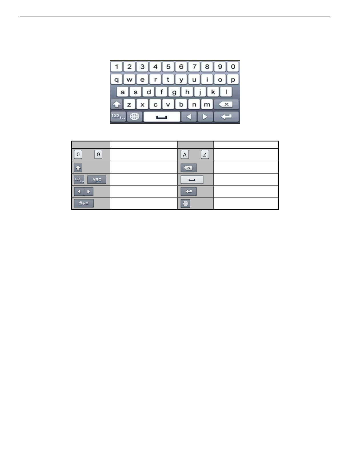
4. Soft Keyboard
The on-screen keyboard allows you to enter characters.
Figure 4, Soft Keyboard
…
Number
Lowercase/Uppercase
Switch the keyboard
Positioning the cursor
Symbols
5. Getting Started
5.1. Starting Up and Shutting Down the DVR
Proper startup and shutdown procedures are crucial to extending the life of the DVR.
5.1.1. Before Starting
Check that the voltage of the external power supply is the same with the DVR’s requirement, and
the ground connection is working properly.
5.1.2. Starting the DVR
1. Check that the power supply is plugged into an electrical outlet. It is HIGHLY recommended
that an Uninterruptible Power Supply (UPS) be used in conjunction with the device.
…
English letter
Backspace
Space
Enter
Reserved
UM DS-90xxHUHI-F8/N User Manual 041717NA 14
2. Turn on the power switch on the rear panel (16 channel only), and the Power indicator LED
should turn on indicating that the unit is starting up.
3. After startup, the Power indicator LED remains on.
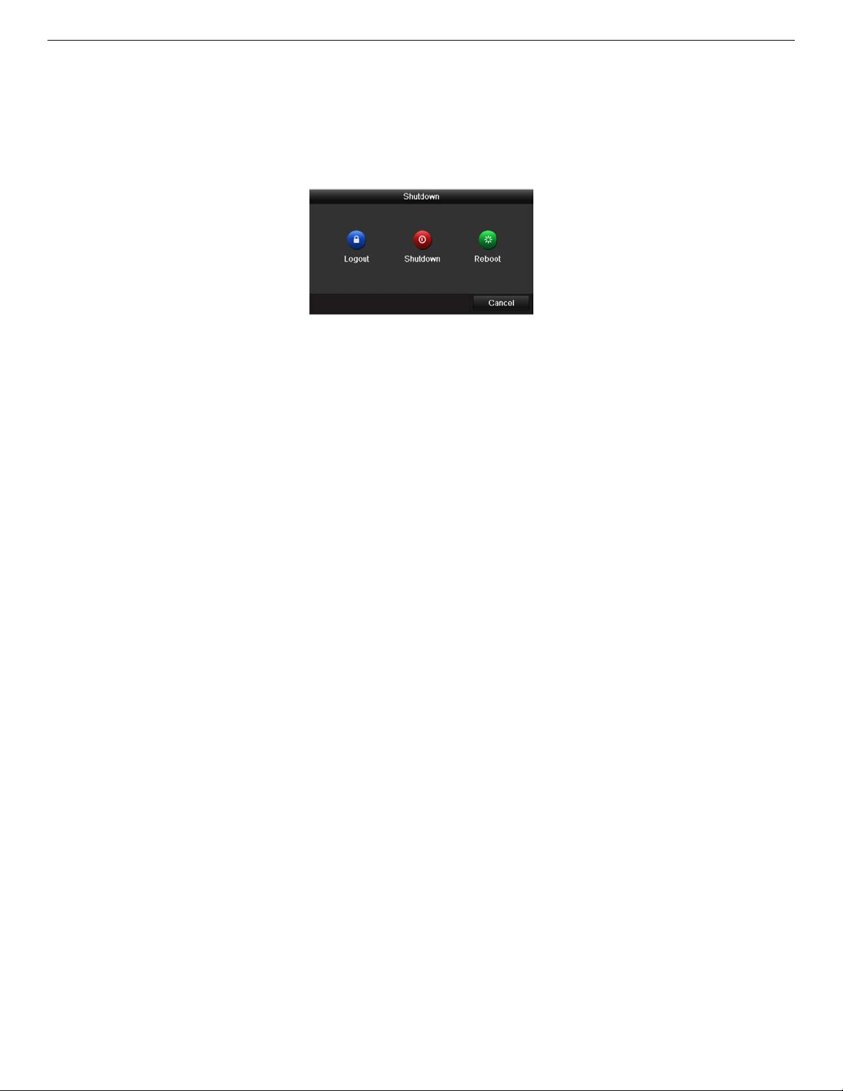
5.1.3. Shutting Down the DVR
1. Enter the Shutdown menu, Menu > Maintenance > Shutdown (icon in lower left corner).
Page 16
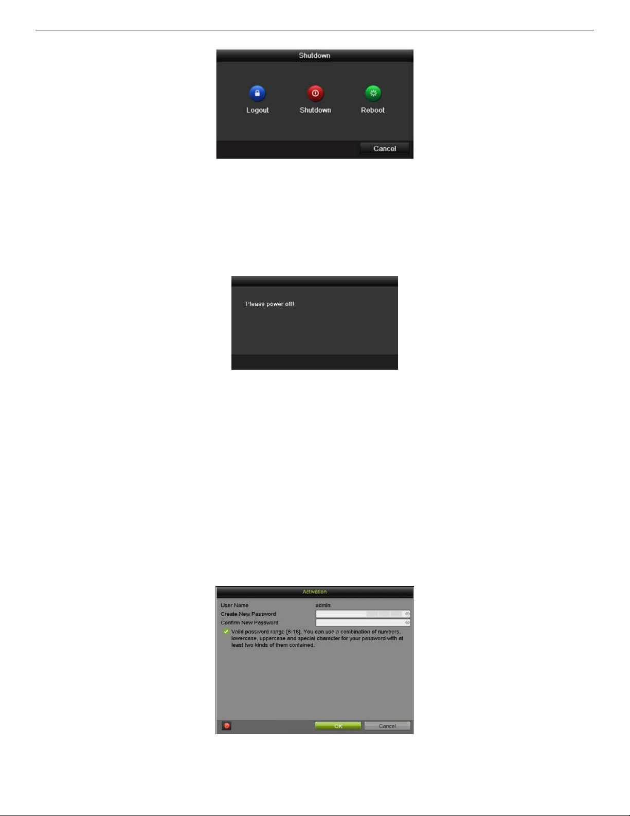
Figure 5, Shutdown Menu
2. Select the Shutdown button.
. Click the Yes button.
3
4. Turn off the rear panel power switch (16 channel only) when the “Please Power Off” prompt
appears.
5.1.4. Rebooting the DVR
While in the Shutdown menu, you can also reboot the DVR.
1. Enter the Shutdown menu by clicking Menu > Shutdown.
2. Click the Logout button to log out, or the Reboot button to reboot, the DVR.
5.2. Activating the Device
For first-time access, you must activate the device by creating an admin password. You can also activate
the device via a Web browser, the SADP program, or client software.
1. Input the same password in the Create New Password and Confirm New Password fields.
Figure 6, Shutdown Prompt
Figure 7, Setting Admin Password
UM DS-90xxHUHI-F8/N User Manual 041717NA 15
Page 17
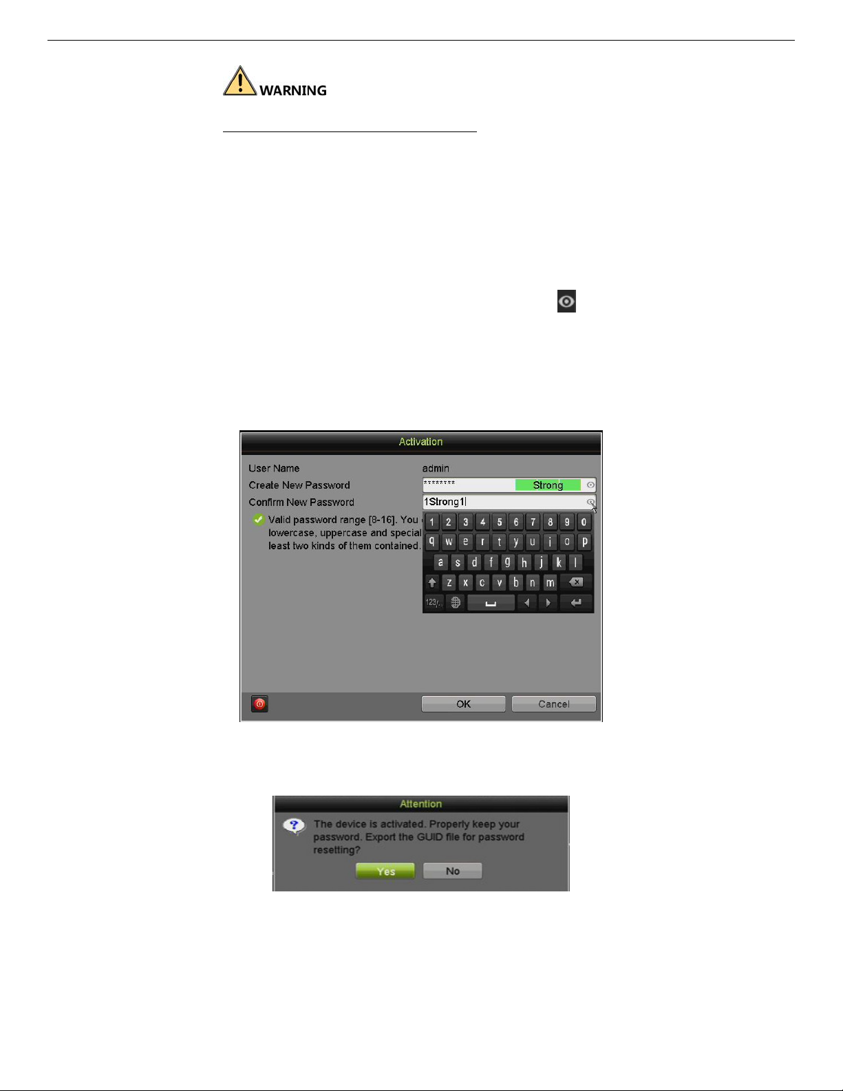
STRONG PASSWORD RECOMMENDED – We highly recommend
you create a strong password of your own choosing (using a
minimum of 8 characters, including at least three of the following
categories: upper case letters, lower case letters, numbers, and
special characters.) in order to increase the security of your
product. We also recommend that you reset your password
regularly. Especially in a high security system, resetting the
password monthly or weekly can better protect your product.
2. Click OK to save the password and activate the devic
NOTE: Clear-text password is supported. Click the icon and you will see
clear text of the password. Click the icon again and the the password
again becomes hidden.
If you update an old version to the new version, the following dialog
box will pop up once the device starts up. Click YES and follow the
prompts to set a strong password.
e.
Figure 8, Password Reveal
3. After the device is activated, the Attention box pops up.
Figure 9, Attention
4. (Optional) Generate and save a GUID (Globally Unique
reset the password. (The GUID (also known as a password key) is unique to each machine..
1) Insert a USB flash disk into the DVR’s USB port.
UM DS-90xxHUHI-F8/N User Manual 041717NA 16
Identifier) password recovery key to be used to
Page 18
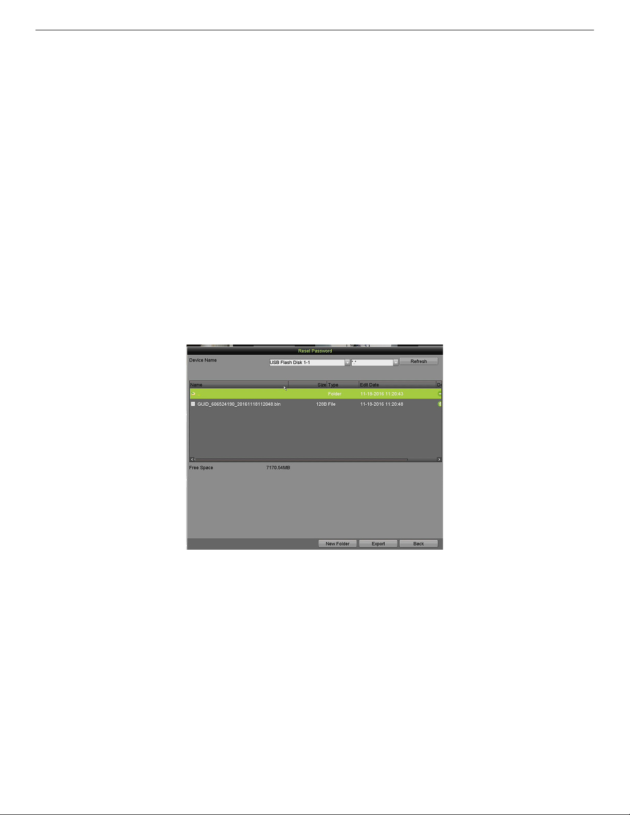
2) Click the Yes button to export the GUID password recovery key. The Reset Password interface
pops up.
3) Navigate to the USB flash disk.
4) Click the New Folder button to create a folder on the USB flash disk. If saving the GUID from
multiple machines, create a name for the folder that identifies the machine (e.g., “Jones Home,
PO3243…”).
5) Double click on the new folder to switch to that location for saving.
6) Click the E
saved GUID file.
NOTE: The first nine digits after GUID_ is the serial number of the unit from
If multiple GUIDs exist for the same unit, always use the file with the
A GUID can be used only once. Generate and export a new GUID
xport button to export the GUID file to the USB flash disk. The system will show the
which the GUID was exported. Digits after the serial number are the
date of export.
latest date.
once the issued GUID has been used.
Figure 10, Export GUID File
UM DS-90xxHUHI-F8/N User Manual 041717NA 17
Page 19
6. Using the Unlock Pattern for Login
Configure the unlock pattern for device login by the admin.
6.1. Configuring the Unlock Pattern
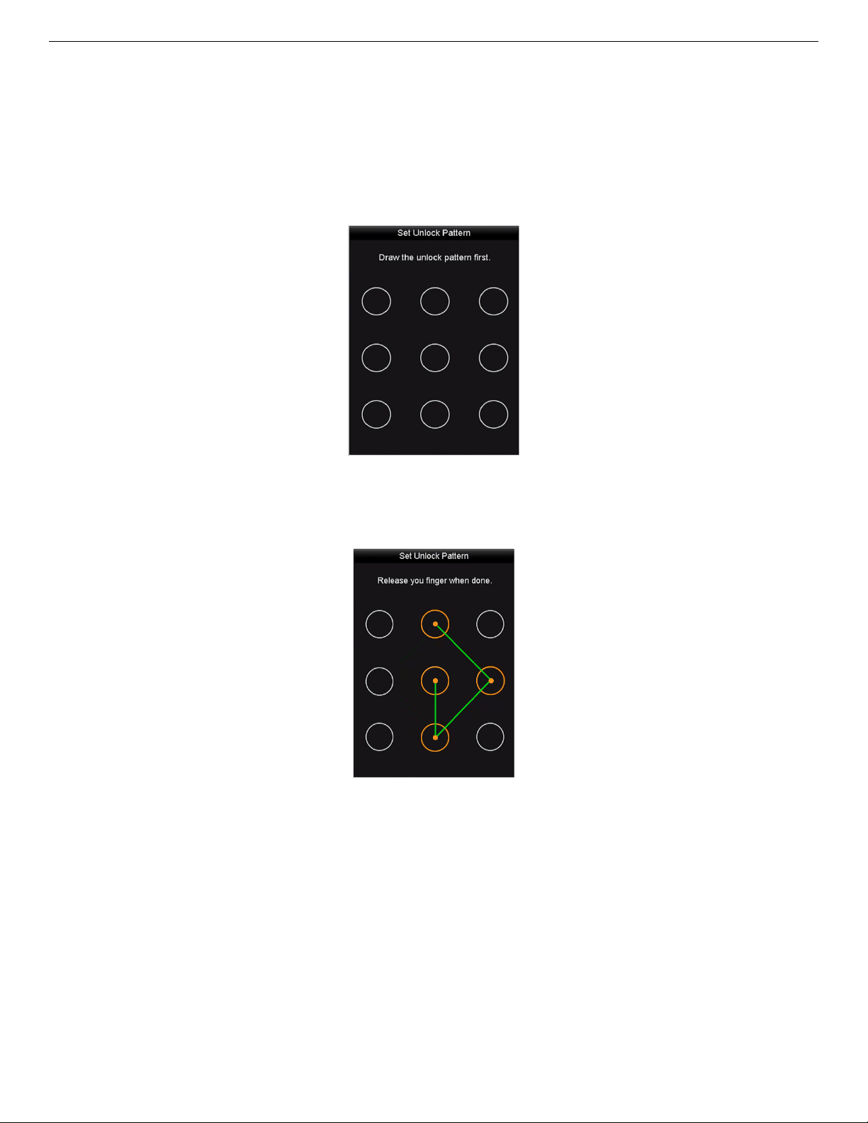
After the device is activated, you can enter the following interface to configure the device unlock pattern.
Figure 11, Set Unlock Pattern
1. Use the mouse to draw a pattern among the nine dots on the screen. Release the mouse when the
pattern is done.
Figure 12, Draw the Pattern
NOTE: Connect at least four dots to draw the pattern. Each dot can be
connected once only.
2. Draw the same pattern again to confirm it. When the two patterns match, the pattern is configured
successfully.
UM DS-90xxHUHI-F8/N User Manual 041717NA 18
Page 20
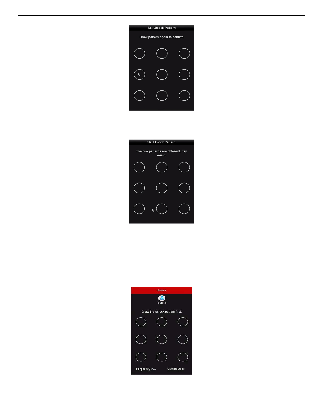
Figure 13, Confirm the Pattern
NOTE: If the two patterns are different, you must set the pattern again.
Figure 14, Reset the Pattern
6.2. Logging in via Unlock Pattern
NOTE: Only the
the pattern before unlocking.
1. Right click the mouse on the screen and select the menu to enter the interface.
admin
user has permission to unlock the device. Configure
Figure 15, Draw the Unlock Pattern
UM DS-90xxHUHI-F8/N User Manual 041717NA 19
Page 21

2. Draw the pre-defined pattern to unlock to enter the menu operation.
NOTE: Right click the mouse to log in via the normal mode.
If you have forgotten your pattern, select the Forget My Pattern or
Switch User option to enter the normal login dialog box.
If the pattern you draw is different from the pattern you have
configured, try again.
If you have drawn the wrong pattern seven times, the account will be
locked for one minute.
7. Login and Logout
7.1. User Login
You must log in to the device before operating the menu and other functions
1. Select the User Name in the drop-down list.
Figure 16, Normal Login Dialog Box
Figure 17, Login Interface
2. Input the Password.
. Click OK to log in.
3
NOTE: Clear-text password is supported. Click the icon to see clear text
of the password. Click the icon again to hide the password.
UM DS-90xxHUHI-F8/N User Manual 041717NA 20
Page 22
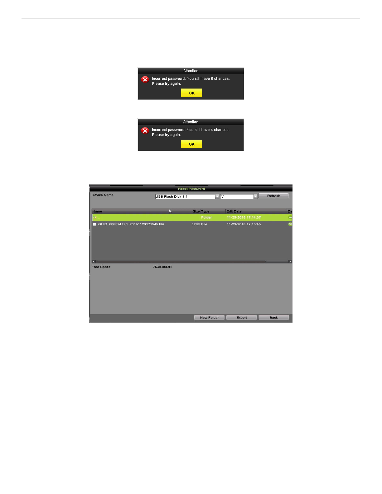
In the Login interface, for the admin, if you have entered the wrong
password seven times, the account will be locked for 60 seconds. For
an operator, if you have entered the wrong password five times, the
account will be locked for 60 seconds.
Figure 18, User Account Protection for the Admin
Figure 19, User Account Protection for the Operator
4. (Optional) If you forget the password, click Forget Password to pop up the Import GUID interface.
Figure 20, Import GUID File
5. Select the GUID file from the USB flash disk and click Import to display Reset Password interface.
UM DS-90xxHUHI-F8/N User Manual 041717NA 21
Page 23
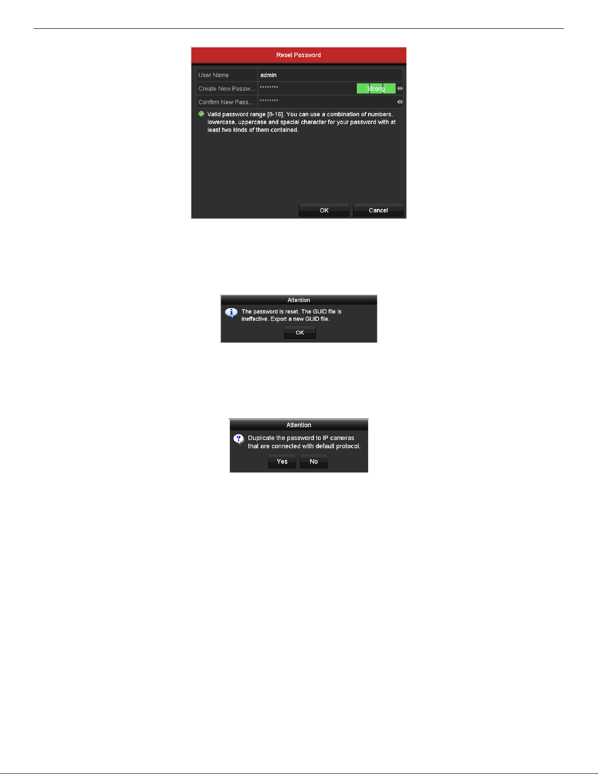
Figure 21, Reset Password
6. Input the new password and confirm the password.
7. Click OK to save the new password. Then the Attention box pops up as shown below.
Figure 22, GUID File Imported
8. Click the OK button, and the Attention box pops up to remind you to duplicate the password of the
device to IP cameras that are connected with default protocol. Click Yes to duplicate the password or
No to cancel it.
Figure 23, Duplicate the Password
NOTE: If you want to retrieve the password when you forget it, you must
export the GUID file first.
Once the password has been reset, the GUID file becomes ineffective.
You can export a new GUID file.
UM DS-90xxHUHI-F8/N User Manual 041717NA 22
Page 24
7.2. User Logout
After logging out, the monitor turns to live view mode, and if you want to perform some operations, you will
need to enter the user name and password to log in again.
1. Enter the Shutdown menu, Menu > Shutdown.
2. Click Logout.
Figure 24, Logout
NOTE: After you have logged out of the system, menu operations on the
screen are invalid. Input a user name and password to unlock the
system.
8. Adding Cameras
8.1. Analog Cameras
8.1.1. Adding Analog Cameras
Analog cameras are enabled by default; no further action is required.
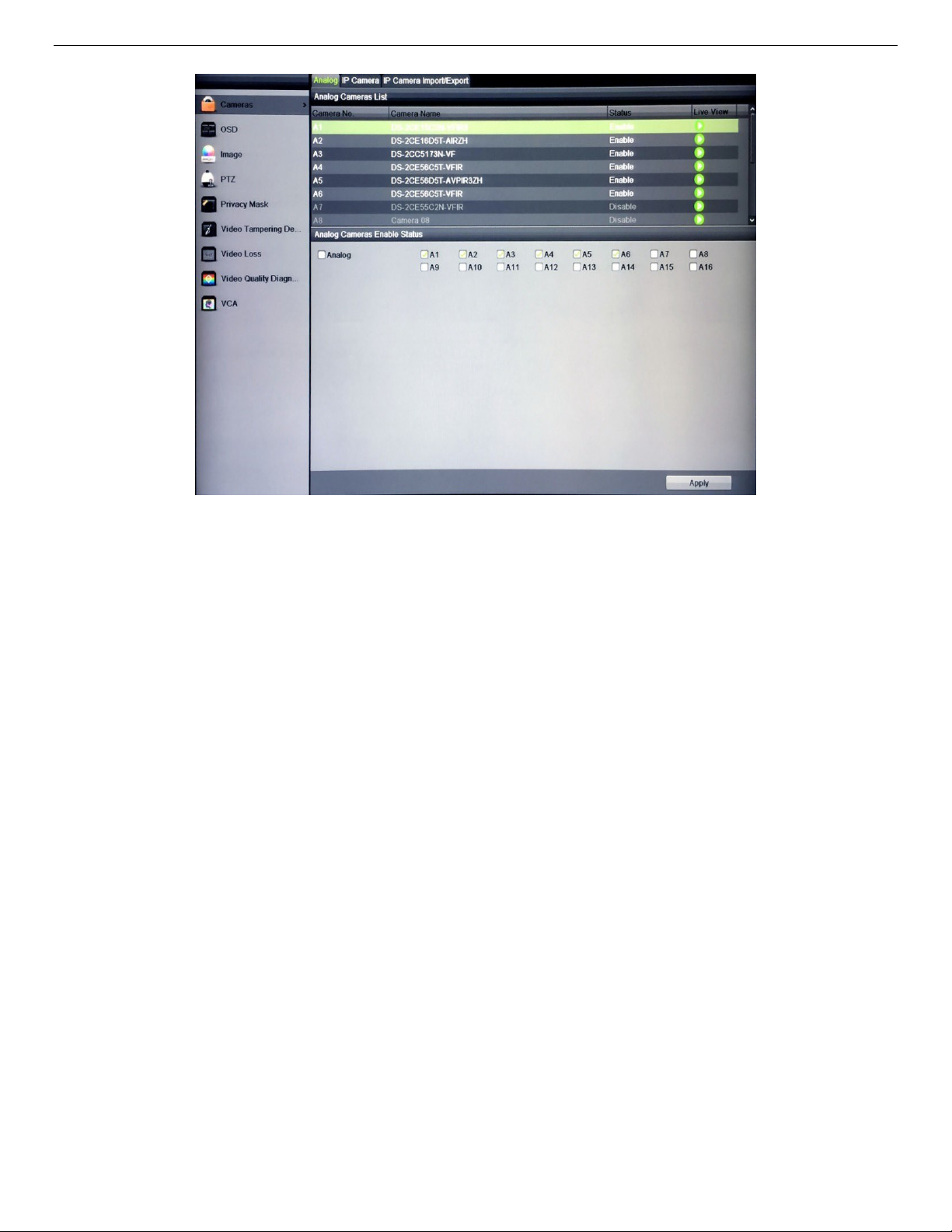
8.1.2. Disabling Analog Cameras To Increase Number of IP Cameras
OTE: Disabling an analog camera allows substitution of a network (IP)
N
1. Go to MENU > CAMERAS > ANALOG (TAB).
2. Analog Camera List will display all enabled cameras.
3. Disable analog cameras in the Analog Cameras Enable Status section:
- Uncheck the camera checkbox of any camera(s) you wish to disable.
camera in its place, up to 10 IP cameras maximum for
DS-7308HUHI-F4/N and up to 18 IP cameras maximum for
DS-7316HUHI-F4/N.
- Check the Analog checkbox to disable/enable all analog cameras.
4. Press APPLY to save settings.
UM DS-90xxHUHI-F8/N User Manual 041717NA 23
Page 25
8.2. IP Cameras
8.2.1. Adding IP Cameras
NOTE: DS-73xxHUHI-F4/N DVRs support IP cameras up to 8 MP.
1. Go to MENU > CAMERAS > IP CAMERA (TAB).
2. Press the REFRESH button to update the camera list:
- Cameras listed in yellow are cameras that have been detected on the network, but not
- Cameras listed in white are cameras that have been added to view on the DVR.
NOTE: If the camera you want to add does not appear on the list, make sure
Figure 25, Add Analog Cameras Window
added to view on the DVR.
it is on the same network as the DVR. If it is on the same network, you
can add the camera manually by pressing the CUSTOM ADDING
button to display the Add IP Camera (Custom) window (Figure 27).
3. Fill out all relevant information and press the OK button.
UM DS-90xxHUHI-F8/N User Manual 041717NA 24
Page 26
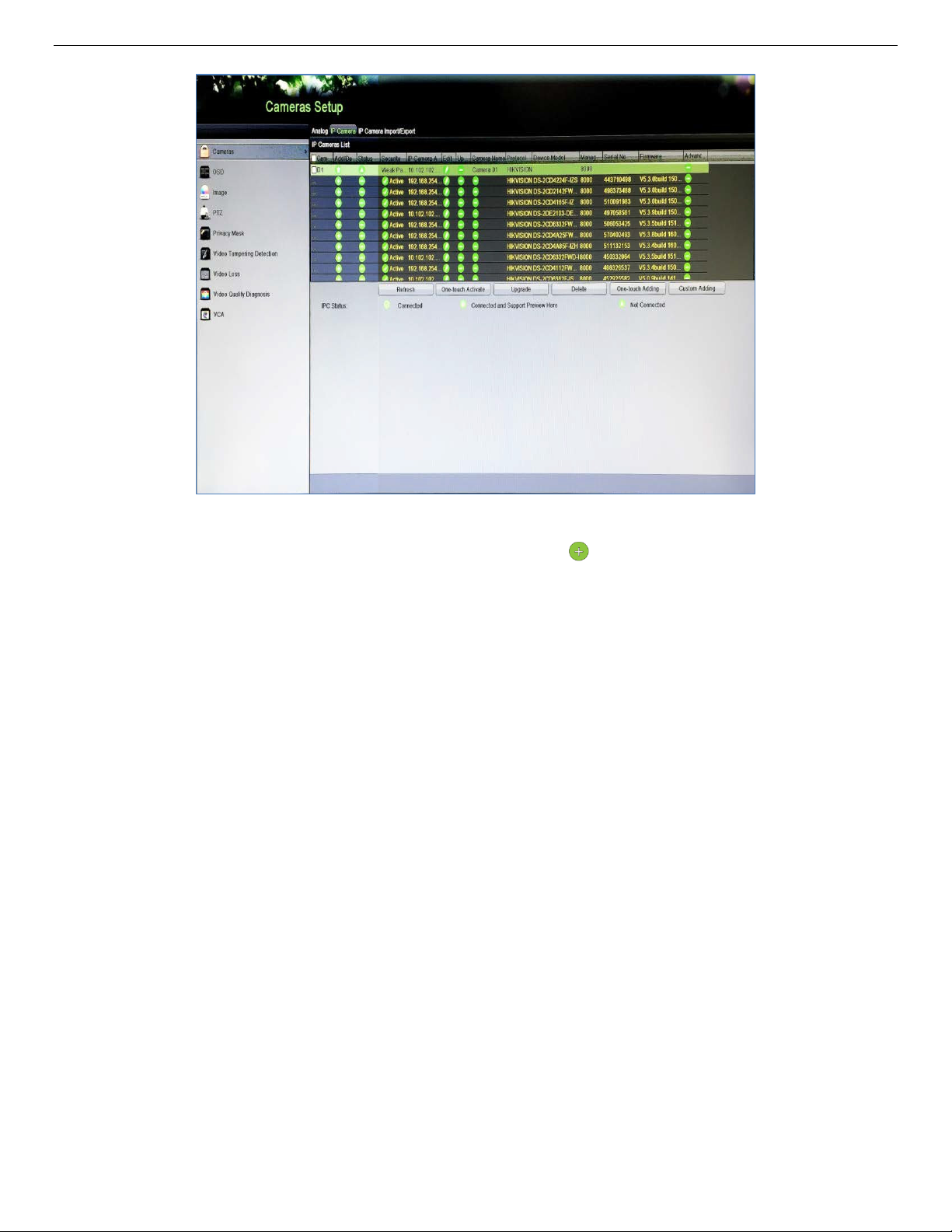
Figure 26, Cameras Setup: IP Camera
- To add a camera(s) to the DVR: Click the icon next to an active (yellow highlighted)
camera to add a single camera to the DVR
- Click the One-Touch Adding button to add all active (yellow highlighted) cameras to the
DVR
- The DVR will check the IP camera’s password against i
ts own password:
- If the IP Camera’s and DVR’s Passwords Match — Camera name will turn white and the
camera will be added to the DVR.
- If the IP Camera’s and DVR’s Passwords Do Not Match — The cameras will be added
with incorrect passwords and will be locked. If the password of the camera does not match
the password of the NVR see Custom Adding IP Camera section, below.
NOTE: If the camera has not been activated, you will be prompted to activate
it by assigning a secure password. See Activating Camera, above.
UM DS-90xxHUHI-F8/N User Manual 041717NA 25
Page 27
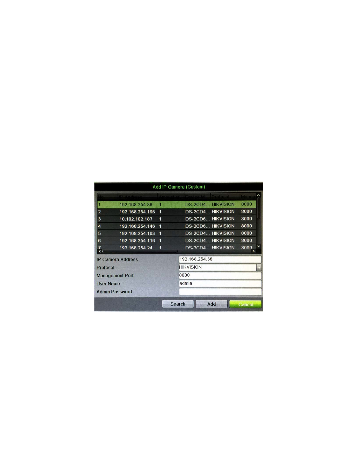
8.2.2. Custom Adding IP Camera
If the camera you want to add does not appear on the list, add the camera as follows:
1. Press the CUSTOM ADDING button to add the camera manually.
2. In the Add IP Camera (Custom) window, enter the following information:
- IP Camera Address
- Protocol
- Management Port
- User Name
- Admin Password
3. Press Add button.
Figure 27, Add IP Camera (Custom) Window
8.2.3. Modify IP Camera Settings
1. Go to MENU > CAMERAS > IP CAMERA.
2. Click the following icons to manage cameras:
NOTE: To change camera name, go to OSD.
UM DS-90xxHUHI-F8/N User Manual 041717NA 26
Page 28
SECURITY: Shows camera status
(strong/medium/weak/risky)
IP Camera Management Icons
Icon Explanation Icon Explanation
EDIT (Pen): Press to edit basic IP
camera parameters (must be in LAN2 range)
DISCONNECTED (!): Camera is disconnected;
click the icon to get camera’s exception information
ADD (+): Press to add the detected IP
camera
DELETE (Trash Can): Press to delete the
camera
PLAY (Right Triangle): Play connected camera’s
live video
UPGRADE (Up Arrow): Upgrade the connected
camera’s firmware
REPAIR (?): Press to attempt to repair thE
connection
Security
Column
ADVANCED (Gear): Press to go to
advanced settings window.
DASH: No advanced settings
available for this camera
(active/inactive) or password strength
8.2.4. Upgrade Camera Firmware
. Download the appropriate firmware from www.hikvision.com.
1
2. Unzip (extract) the firmware onto a USB stick.
3. Check the checkboxes next to each camera you would like to upgrade.
4. Click the Upgrade button.
5. Browse to find the firmware file to be used for the upgrade.
6. Click OK.
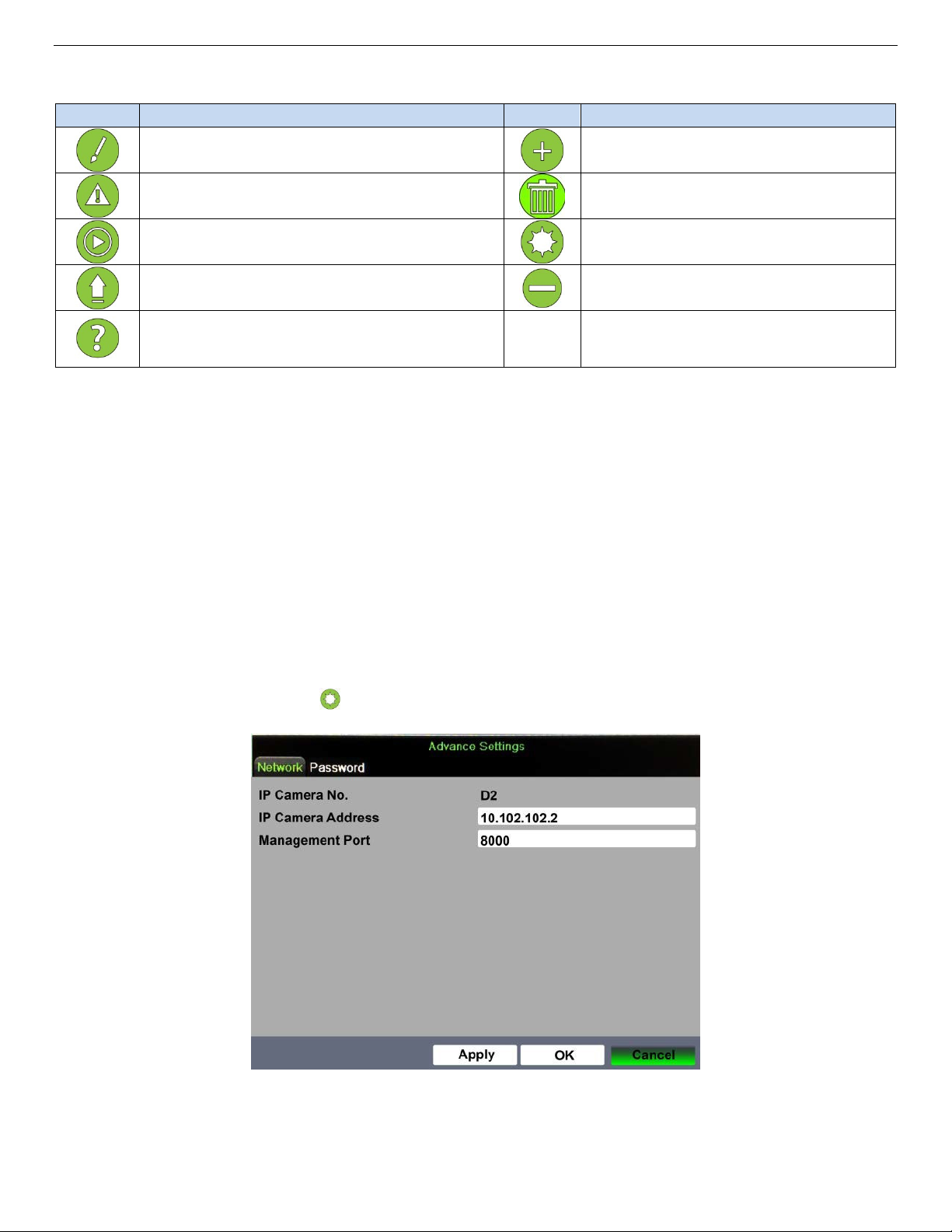
8.2.5. Advanced Settings
. Click the Advanced icon to display the Advance Settings window.
1
Figure 28, Advanced Settings: Network
2. Enter information into the following fields, as appropriate:
UM DS-90xxHUHI-F8/N User Manual 041717NA 27
Page 29
- IP Camera No. (Read Only) — Displays the camera number
- IP Camera Address — Enter the camera IP address
- Management Port — Enter the camera management port (default = 8000)
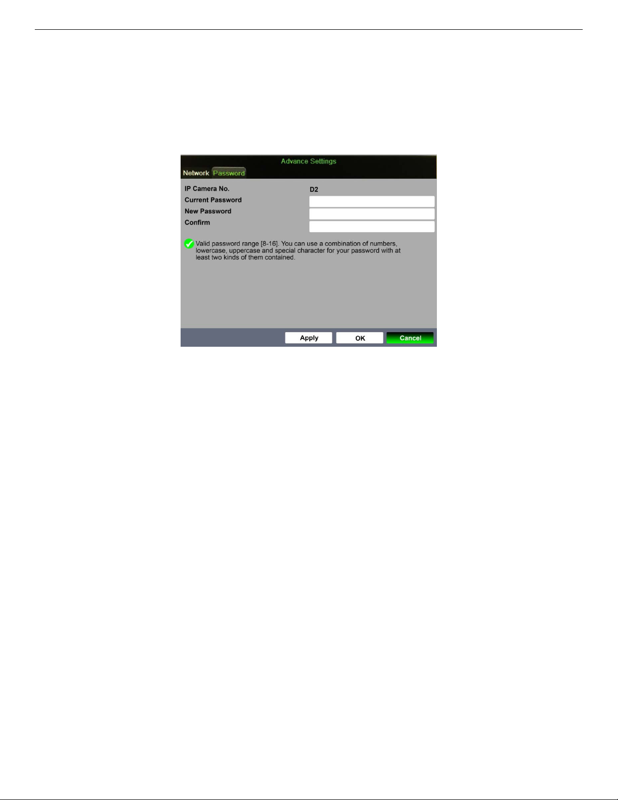
3. Click the Password tab to display the Password window.
Figure 29, Advanced Settings: Password
4. Enter current password in Current Password field.
5. Enter new password in New Password field.
6. Re-type new password in Confirm field.
. Click on the Apply button to validate the new password
7
8. Click the OK button to accept the new password.
UM DS-90xxHUHI-F8/N User Manual 041717NA 28
Page 30
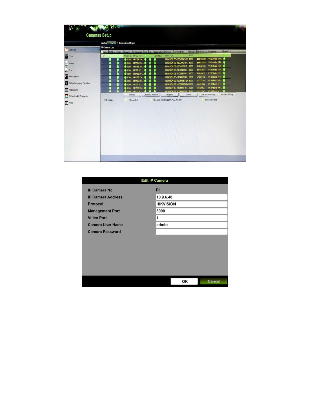
Figure 30, Cameras Setup > IP Camera Screen
Figure 31, Edit IP Camera
8.3. Activating Camera
A camera must be activated before first use. To activate a camera before adding it to the DVR:
1. View the status of the camera in the Camera List “Security” column.
• Active — Camera has been activated; no further activation necessary
• Inactive
• Strong/Medium/Weak/Risky
UM DS-90xxHUHI-F8/N User Manual 041717NA 29
— Camera is inactive; it must be activated before adding it to the DVR
— Displays the camera’s password strength
Page 31

2. Press One Touch Activate button.
•
Activation message will appear on the screen prompting user to activate the device (Figure 32).
•
Username field will be greyed-out with the username set to “admin.”
3. Type a password of your choosing (see “Password Strength Levels” table for guidelines).
• The password strength will be displayed, accompanied by a color indicator.
• Activation will not be allowed unless password is of acceptable strength.
4. Retype the password into the “Confirm Password” field.
Figure 32, Activation Window
NOTE: The strength level indicator colors can vary by activation process,
model number, and device type.
Figure 33, Level 0 (Inadequate) Strength Password
UM DS-90xxHUHI-F8/N User Manual 041717NA 30
Page 32

Figure 34, Invalid Password Message
Figure 35, Level 1 Password Strength
Figure 36, Level 2 Password Strength
UM DS-90xxHUHI-F8/N User Manual 041717NA 31
Page 33

Figure 37, Level 3 and Level 4 Password Strength
5. After an acceptable password has been created, a confirmation message will appear (Figure 38).
6. Press the OK button to proceed.
Figure 38, Activation Confirmation Message
UM DS-90xxHUHI-F8/N User Manual 041717NA 32
Page 34

Password Strength Levels
STRENGTH LEVEL DESCRIPTION
DVRs
DVRs
DVRs
DVRs
Level 0 (Risky)
will not
accept a Level 0 password
Level 1 (Weak)
will
accept a Level 1 password
Level 2 (Medium/Fair)
will
accept a Level 2 password
Level 3 (Strong)
will
accept a Level 3 password
NOTE 1: The strength level indicator colors can vary by activation process,
NOTE 2: PASSWORD CHARACTERS ALLOWED (ASCII Only):
Password length is fewer than eight characters, contains only one type of
character, is the same as the user name, and/or is the mirror writing of the
user name. This type of password
Password contains two kinds of characters. The combination is number +
lowercase letter or number + uppercase letter, and the password length
is at least eight characters. This type of password
Password contains two types of characters. The combination is neither
number + lowercase letter
password length is at least eight characters. This type of password
accepted.
Password contains more than three types of characters, and the password
length is at least eight characters. This type of password
will not
nor
number + uppercase letter, and the
be accepted.
will
be accepted.
will
will
be
be accepted.
model number, and device type. Typical: Risky (no color), Weak (pink),
Fair (yellow), Strong (green).
• Lowercase ASCII Letters
a b c d e f g h I j k l m n o p q r s t u v w x y z
• Uppercase ASCII Letters
A B C D E F G H I J K L M N O P Q R S T U V W X Y Z
• Numerals
0 1 2 3 4 5 6 7 8 9
• Special Characters
. - _ : / @ , ? ! ‘ ( ) $ & “ [ ] { } # % ^ * + = \ | < >
UM DS-90xxHUHI-F8/N User Manual 041717NA 33
Page 35

9. Live View
Live View shows the video image from each camera in real time. The DVR will automatically enter Live View mode
when powered on. It is also at the very top of the menu hierarchy, thus hitting the ESC key multiple times
(depending on which menu you’re on) will take you back to Live View mode.
9.1. Live View Settings
9.1.1. General
Figure 39, Live View Settings
1. Go to MENU > SYSTEM CONFIGURATION > LIVE VIEW > GENERAL.
2. Set the following values, as desired:
• Video Output Interface – Use pull-down menu to select the monitor to use for Live View.
• Live View Mode – Use pull-down menu to select the monitor view layout.
• Dwell Time – Use pull-down menu to select the seconds to wait between Live View
screens.
• Enable Audio Output – Check to enable audio if the camera is so equipped.
• Volume – Click on green squares to set volume.
• Event Output – Use pull-down menu to select the monitor to use for events.
• Full Screen Monitoring Dwell Time –
between the event monitor screens.
Use pull-down menu to select the seconds to wait
UM DS-90xxHUHI-F8/N User Manual 041717NA 34
Page 36

9.1.2. View
This section explains how to assign cameras to Live View screen positions.
Figure 40, Live View View Settings
1. Go to MENU > SYSTEM CONFIGURATION > LIVE VIEW > VIEW.
2. Use pull-down menu to select the Video Output Interface you want to configure.
3. Click on a screen layout (directly beneath screen po
4. Highlight a screen position on the top right section of the screen.
5. Double click a camera on the camera list on the left of the screen to assign the camera to the
highlighted screen position.
6. Repeat for all screen positions.
7. Press the Apply button.
9.1.3. Channel-Zero Encoding
Channel-Zero Encoding combines all video streams into one lower resolution, lower bandwidth
channel. Do the following to enable Channel-Zero Encoding:
1. Go to MENU > SYSTEM CONFIGURATION > LIVE VIEW > CHANNEL-ZERO ENCODING.
sitions) that you want the monitor to have.
2. Check the Enable Channel-Zero Encoding checkbox.
3. Use the pull-down menu to select the channel frame rate.
4. Use the pull-down menu to select the M
ax.(imum) Bitrate Mode.
5. Use the pull-down menu to select the Max.(imum) Bitrate in Kbps.
6. Press the Apply button.
UM DS-90xxHUHI-F8/N User Manual 041717NA 35
Page 37

Figure 41, Channel-Zero Encoding
9.1.4. Live View Icons
In live view mode, there are icons at the right top of the screen for each channel, showing the
status of the record and alarm in the channel, so that you can know whether the channel is
recorded, or whether there are alarms as soon as possible.
Icons Description
Alarm (video loss, tampering, motion detection, VCA or sensor alarm)
Record (manual record, schedule record, motion detection or alarm triggered record)
Alarm & Record
Event/Exception (motion detection, sensor alarm or exception information)
9.2. Operations in Live View Mode
In Live View mode, there are many functions provided. The functions are listed below.
• Single Screen: show only one screen on the monitor.
• Multi-screen: show multiple screens on the monitor simultaneously.
• Start Auto-Switch: the screen is auto switched to the next one. You must set the dwell time for each
screen on the configuration menu before enabling the auto-switch. Menu > Configuration > Live View >
Dwell Time.
• Start Recording: normal record and motion detection record are supported.
• Output Mode: select the output mode to Standard, Bright, Gentle, or Vivid.
• Playback: play back the recorded videos for the current day.
UM DS-90xxHUHI-F8/N User Manual 041717NA 36
Page 38

Name
Description
Menu
Enter the main menu of the system by right clicking the mouse
Single Screen
Switch to the single full screen by choosing channel number from the drop
-
down list
Multi
-Screen
Adjust the screen layout
by
select
ing from the drop
-
down list.
Previous Screen
Switch to the previous screen
Next Screen
Switch to the next screen
Enable/disable
the auto
-
switch of the screens
Auto
-Switch
Start recording
all channels;
Continuous
Recor
d and Motion Detection Record
are
selectable from the drop
-
down list
Add IP Camera
A shortcut to enter the IP camera management interface.
(For HDVR series only
)
Enter the playback interface and start playing back the video of the selected channel
immediately.
PTZ Control
Shortcut to enter the PTZ control interface of the selected camera
Output Mode
Output Mode is configurable with Standard, Bright, G
entle
, and Vivid options
• Aux/Main Monitor: the DVR checks the connection of the output interfaces to define the main and
auxiliary output interfaces. When the aux output is enabled, the main output cannot do any operation,
and you can do some basic operation on the live view mode for the Aux output.
The VGA/HDMI output is the main output. The priority relationship is shown in the following table:
S.N HDMI VGA Main Output
1 √ or × √ or × VGA/HDMI
NOTE: √ means the interface is in use, × means the interface is out of use or
the connection is invalid. HDMI and VGA can be used at the same
time.
9.3. Using the Mouse in Live View
Refer to the following table for the description of mouse operations in Live View mode:
Start/Stop
Auto-Switch
Start Recording
Playback
NOTE:
NOTE: The
NOTE:NOTE:
dwell time
of the live view configuration must be set before using Start
Figure 42, Right-Click Menu
UM DS-90xxHUHI-F8/N User Manual 041717NA 37
Page 39

Icons
Description
Icons
Description
Icons
Description
Start
/
Stop
Manual
Record
ing
9.4. Quick Setting Toolbar in Live View Mode
On each channel’s screen, there is a quick setting toolbar that shows when you click the screen.
Figure 43, Quick Setting Toolbar
Instant Playback
PTZ Control
Close Live View
Capture
Fisheye
• Instant Playback shows only the record in last five minutes. If no record is found, it means
Digital Zoom
Face Detection
Live View Strategy
Audio On/Mute
Image Settings
Information
Information
there is no record during the last five minutes.
• Digital Zoom can zoom in the selected area to the full screen. Click and draw to select the
area to zoom in.
UM DS-90xxHUHI-F8/N User Manual 041717NA 38
Figure 44, Digital Zoom
• Image Settings icon can be selected to enter the Image Settings menu. You can drag the
mouse or click
to adjust the image parameters, including brightness, contrast, and saturation..
Page 40

Figure 45, Image Settings
• Face Detection can be enabled on supported cameras if you click the icon. The dialog
pops up. Click Yes and the full-screen live view of the channel is enabled. You can click to
exit from the full-screen mode.
Figure 46, Enable Face Detection
NOTE: You can configure face detection only when it is supportsed by the
connected camera.
• Move the mouse onto the Information icon to show the real-time stream information,
including the frame rate, bit rate, resolution, and stream type.
Figure 47, Information
9.5. Adjusting Live View Settings
Live View settings can be customized according to different needs. You can configure the output interface,
dwell time for screen to be shown, mute or turning on the audio, the screen number for each channel, etc.
7. Enter the Live View Settings interface, Menu > Configuration > Live View.
Figure 48, Live View – General (1)
UM DS-90xxHUHI-F8/N User Manual 041717NA 39
Page 41

Figure 49, Live View – General (2)
The settings available in this menu include:
• Video Output Interface: Selects the output (HDMI, VGA, or 4K) to configure the settings to the
video output interface.
NOTE: Using 4K video output disables VGA output.
• Live View Mode: Selects the display mode to be used for Live View.
• Dwell Time: The time in seconds to dwell between switching of channels when enabling
auto-switch in Live View.
• Enable Audio Output: Enables/disables audio output for the selected camera in the live view
mode.
• Volume: Adjust the volume of the audio output.
• Event Output: Designates the output to show event video. If available, you can select a different
video output interface from the Video Output Interface when an event occurs.
• Full Screen Monitoring Dwell Time: The time in seconds to show alarm event screen.
8. Set the camera order.
9. Click View tab and select the Video Output Interface from the drop-down list.
Figure 50, Live View, Camera Order
UM DS-90xxHUHI-F8/N User Manual 041717NA 40
Page 42

10. Click a window to select it, and then double-click a camera name in the camera list you would like to
display. Setting an ‘X’ means the window will not display any camera.
11. You can also click to start live view of all channels in order and click to stop live view of all
channels. Click or to go to the previous or next page.
12. Click the Apply button.
9.6. Manual Video Quality Diagnostics
The video quality of the analog channels can be diagn
osed manually and you can view the diagnostic
results from a list.
1. Enter the Manual Video Quality Diagnostics interface, Menu > Manual > Manual Video Quality
Diagnostics.
Figure 51, Video Quality Diagnostics
2. Check the checkboxes to select the channels for diagnostics.
3. Click the Diagnose button, and the results will be displayed in a list. You can view the video status and
diagnostics time of the selected channels.
Figure 52, Diagnostics Result
NOTE: Connect the camera to the device for the video quality diagnostics.
Three exception types can be diagnosed: Blurred Image, Abnormal
Brightness, and Color Cast.
UM DS-90xxHUHI-F8/N User Manual 041717NA 41
Page 43

10. PTZ Controls
10.1. Configuring PTZ Settings
Follow the procedure to set the parameters for PTZ. The configuring of the PTZ parameters should be done
before you control the PTZ camera.
1. Enter the PTZ Settings interface, Menu > Camera > PTZ.
Figure 53, PTZ Settings
2. Select the camera for PTZ setting in the Camera drop-down list.
3. Click the PTZ Parameters button to set the PTZ parameters.
Figure 54, PTZ, General
UM DS-90xxHUHI-F8/N User Manual 041717NA 42
Page 44

4. Select the parameters of the PTZ camera from the drop-down list.
NOTE: All the parameters should be exactly the same as the PTZ camera
parameters.
For a connected Coaxitron camera/dome, select the HIKVISION-C
PTZ protocol. Make sure the protocol selected here is supported by
the connected camera/dome.
If HIKVISION-C protocol is selected, all other parameters such as
baud rate, data bit, stop bit, parity, and flow control are not
configurable.
5. (Optional) Click Copy button to copy the settings to
the other channels. Select the channels you want to
copy to and click OK to return to the PTZ Parameters Settings interface.
Figure 55, Copy to Other Channels
6. Click OK to save the settings.
7. (Optional) Check the Enable Omnicast Control checkbox to enable the PTZ control of the selected
camera via Omnicast VMS of Genetec.
10.2. Setting PTZ Presets, Patrols, and Patterns
10.2.1. Before Starting
Please make sure that the presets, patrols, and patterns are supportsed by PTZ protocols.
10.2.2. Customizing Presets
Follow the steps to set the Preset location which you want the PTZ camera to point to when an
event takes place.
1. Enter the PTZ Settings interface, Menu > Camera > PTZ.
UM DS-90xxHUHI-F8/N User Manual 041717NA 43
Page 45

Figure 56, PTZ Settings
2. Use the directional button to point the camera to the location where you want to set the preset;
the zoom and focus operations can be recorded in the preset as well.
3. Enter the preset No. (1 to 255) in the preset text field, and click the Set button to link the
location to the preset.
4. Repeat steps 2 and 3 to save more presets.
NOTE: Click the Clear button to clear the location information of the preset, or
10.2.3. Calling Presets
is feature enables the camera to point to a specified position such as a window when an event
Th
takes place.
1. Click the PTZ button in the lower-right corner of the PTZ setting interface, or press the PTZ
button on the front panel, or click the PTZ Control icon in the quick setting bar, or select
the PTZ option in the right-click menu to show the PTZ control panel.
2. Choose Camera in the drop-down list.
3. Click the General tab to show the general settings of the PTZ control.
click the Clear All button to clear the location information of all the
presets.
UM DS-90xxHUHI-F8/N User Manual 041717NA 44
Page 46

Figure 57, PTZ Panel, General
4. Click to enter the preset No. in the corresponding text field.
5. Click the Call Preset button to call it.
NOTE: When a Coaxitron camera/dome is connected and the PTZ protocol is
selected to HIKVISION-C, call the preset 95 to enter the menu of the
connected Coaxitron camera/dome. Use the directional buttons on the
PTZ control panel to operate the menu.
10.2.4. Customizing Patrols
Patrols can be set to move the PTZ to different key points and have it stay there for a set duration
before moving on to the next key point. The key points are corresponding to the presets. The
presets can be set following the steps above in
1. Enter the PTZ Settings interface, Menu > Camera > PTZ.
Customizing Presets
.
Figure 58, PTZ Settings
2. Select patrol No. in the drop-down list of patrol.
UM DS-90xxHUHI-F8/N User Manual 041717NA 45
Page 47

3. Click the Set button to add key points for the patrol.
Figure 59, Key Point Configuration
4. Configure key point parameters such as the key point No., duration of staying for one key point,
and speed of patrol.
NOTE:
NOTE: The key point corresponds to the preset. The Key Point No.
NOTE:NOTE:
determines the order the PTZ will follow while cycling through the
patrol. Duration refers to the time to stay at the corresponding key
point. Speed defines the speed at which the PTZ will move from one
key point to the next.
5. Click the Add button to add the next key point to the patrol, or click the OK button to save the
key point to the patrol.
6. You can delete all the key points by clicking the Clear button for the selected patrol, or click the
Clear All button to delete all the key pints for all patrols.
10.2.5. Calling Patrols
Calling a patrol moves the PTZ according the predefined patrol path.
1. Click the PTZ button in the lower-right corner of the
button on the front panel, or click the PTZ Control icon in the quick setting bar, or select
the PTZ option in the right-click menu to show the PTZ control panel.
2. Click the General tab to show the general settings of the PTZ control.
PTZ Settings interface, or press the PTZ
Figure 60, PTZ Panel, General
3. Select a patrol in the dropdown list and click the Call Patrol button to call it.
UM DS-90xxHUHI-F8/N User Manual 041717NA 46
Page 48

4. You can click the Stop Patrol button to stop calling it.
10.2.6. Customizing Patterns
Patterns can be set by recording the movement of the PTZ. You can call the pattern to move the
PTZ according to the predefined path.
1. Enter the PTZ Settings interface, Menu > Camera > PTZ.
2. Choose pattern number in the drop-down list.
3. Click the Start button, and click corresponding butt
camera. Click the Stop button to stop it.The PTZ movement is recorded as the pattern.
10.2.7. Calling Patterns
Follow the procedure to move the PTZ camera according to the predefined patterns.
1. Click the PTZ button in the lower-right corner of the PTZ Settings interface, or press the PTZ
button on the front panel, or click the PTZ Control icon in the quick setting bar, or select
the PTZ option in the right-click menu to show the PTZ control panel.
2. Click the General tab to show the general settings of the PTZ control.
Figure 61, PTZ Settings
ons in the control panel, to move the PTZ
UM DS-90xxHUHI-F8/N User Manual 041717NA 47
Page 49

Figure 62, PTZ Panel, General
3. Click the Call Pattern button to call it.
4. Click the Stop Pattern button to stop calling it.
10.2.8. Customizing Linear Scan Limit
Enable Linear Scan to trigger the scan in the horizontal direction in the predefined range.
NOTE:
NOTE: This function is supported by certain models.
NOTE:NOTE:
1. Enter the PTZ Settings interface, Menu > Camera > PTZ.
Figure 63, PTZ Settings
2. Use the directional button to wheel the camera to the location where you want to set the limit,
and click the Left Limit or Right Limit button to link the location to the corresponding limit.
NOTE:
NOTE: The speed dome starts linear scan from the left limit to the right limit.
NOTE:NOTE:
The left limit must be left of the right limit. The angle from the left limit
to the right limit must be no more than 180°.
UM DS-90xxHUHI-F8/N User Manual 041717NA 48
Page 50

10.2.9. Calling Linear Scan
Follow the procedure to call the linear scan in the predefined scan range.
1. Click the button PTZ in the lower-right corner of the PTZ Settings interface, or press the PTZ
button on the front panel, or click the PTZ Control icon in the quick setting bar to enter
the PTZ setting menu in live view mode.
2. Click the One-Touch tab to show the one-touch function of the PTZ control.
3. Click Linear Scan button to start the linear scan and click the Linear Scan button again to stop
it.
4. Click the Restore button to clear the defined left l
to reboot to have settings take effect.
10.2.10. One-Touch Park
Certain speed dome models can be configured to start a predefined park action (scan, preset,
patrol, etc.) automatically after a period of inactivity (park time).
1. Click the PTZ button in the lower-right corner of the PTZ Settings interface. or press the PTZ
button on the front panel, or click the PTZ Control icon in the quick setting bar to enter
the PTZ setting menu in live view mode.
2. Click the One-Touch tab to show the one-touch function of the PTZ control.
Figure 64, PTZ Panel, One-Touch
imit and right limit data, and the dome needs
UM DS-90xxHUHI-F8/N User Manual 041717NA 49
Page 51

Figure 65, PTZ Panel, One-Touch
3. Click the corresponding button to activate the one-touch park action:
• Park (Quick Patrol): The dome starts patrol from the predefined preset 1 to preset 32 in
order after the park time. Any undefined preset will be skipped.
• Park (Patrol 1): The dome starts moving according to the predefined patrol 1 path after
the park time.
• Park (Preset 1): The dome moves to the predefined preset 1 location after the park time.
NOTE: The park time can be set only through the speed dome configuration
4. Click the button again to inactivate it.
0.2.11. PTZ Control Panel
1
1. Enter the PTZ control panel in one of two ways:
OPTION 1: In the PTZ Settings interface, click the PTZ button on the lower-right corner next
to the Back button.
OPTION 2: In Live View mode, press the PTZ Control button on the front panel, or on the
remote control, or choose the PTZ Control icon in the quick setting bar, or select the
PTZ Control option in the right-click menu.
2. Click the Configuration button on the control panel to enter the PTZ Settings interface.
interface. The default value is 5s.
NOTE: In PTZ control mode, the PTZ panel will be displayed when a mouse
is connected to the device. If no mouse is connected, the icon
appears in the lower-left corner of the window, indicating that this
camera is in PTZ control mode.
UM DS-90xxHUHI-F8/N User Manual 041717NA 50
Page 52

Icon
Description
Icon
Description
Icon
Description
Switch to the
Switch to the
Switch to the
Figure 66, PTZ Control Panel
Description of the PTZ Panel Icons
Direction button
and the
auto-cycle button
The speed of the
PTZ movement
3D-Zoom
Light on/off Wiper on/off
PTZ control
interface
Exit
Zoom+, Focus+,
Iris+
Image
Centralization
one-touch control
interface
Minimize
windows
Menu
Zoom-, Focus-,
Iris-
general settings
interface
UM DS-90xxHUHI-F8/N User Manual 041717NA 51
Page 53

11. Recording Settings
11.1. Configuring Encoding Parameters
11.1.1. Before Starting
1. Make sure that the HDD has been installed. If not, install an HDD and initialize it by going to
Menu > HDD > General.
Figure 67, HDD, General
2. Click the Advanced tab and select HDD storage mode (Menu > HDD > Advanced > Storage
Mode).
• If the HDD mode is
• If the HDD mode is
Quota
, set the maximum record capacity.
Group
, set the HDD group.
Figure 68, HDD, Advanced
3. Enter the Record Parameters interface to configure the encoding parameters, Menu >
Record > Parameters.
UM DS-90xxHUHI-F8/N User Manual 041717NA 52
Page 54

Figure 69, Record Parameters
4. Set the parameters for recording.
A). Select the Record tab to configure.
B). Select a camera from the camera drop-down list.
C). View the Camera Resolution.
NOTE: When HD-TVI input is connected, you can view the information
including the input signal type, resolution, and frame rate (e.g.,
HD-TVI 720P25).
5. Configure the following parameters for the Main Stre
am (Continuous) and the Main Stream
(Event): Stream Type: Set the stream type to be Video or Video & Audio.
6. Resolution: Set recording resolution.
NOTE: Supports up to 3 MP resolution (up to 8 MP resolution for IP cameras).
If a 3 MP signal input is connected to the channel, the recording
resolution will be adjusted to 3 MP (8 MP if 8 MP IP camera) and the
frame rate will be adjusted to 12 fps automatically if the resolution and
frame rate are not configured manually.
If the 3 MP camera is connected to a channel that supports up to
1080p signal input, it will switch to 1080p signal input. When the 3 MP
signal is switched to 1080p signal, PAL will be switched to 1080p/25
Hz and NTSC will be switched to 1080p/30 Hz.
Analog signal inputs including HD-TVI (including 3 MP, 1080p, and
720p signal), can be connected. The analog signal inputs are
recognized automatically and can be mixed randomly.
If the configured encoding resolution conflicts with the resolution of
the front-end camera, the encoding parameters will adjust
automatically to meet the front-end camera (e.g., if the resolution of
the front-end camera is 720p, then the encoding resolution of the
main stream will adjust to 720p automatically).
UM DS-90xxHUHI-F8/N User Manual 041717NA 53
Page 55

960 × 1080 (1080p Lite) resolution is available when the 1080p Lite is
enabled in the Record > Advanced Settings interface.
7. Bitrate Type: Set the bitrate type to be Variable or Constant.
8. Video Quality: Set the video quality of recording, with 6 levels configurable.
NOTE: The Stream Type, Resolution, Bitrate Type, and Video Quality are not
configurable for the Main Stream (Event) of the IP Camera.
9. Frame Rate: Set the frame rate of recording.
0. Max. Bitrate Mode: Set the mode to General or Custom.
1
11. Max Bitrate (Kbps): Select or customize the maximum bit rate for recording.
12. Max. Bitrate Range Recommended: A recommended max. bit rate range is provided for
reference.
13. Max. Average Bitrate (Kbps): Set the max. average bit rate which refers to the average amount
of data transferred per unit of time.
NOTE: When the connected IP camera does not support H.265, only H.264
can be selected for the video encoding.
14. Check the Enable H.264+ or Enable H.265+ checkbox to enable this function. Enabling it helps
to ensure the high video quality with a lower bitrate.
NOTE: If the connected IP camera supports H.265 and H.265 is enabled,
Enable H.265+ is shown on the interface instead of Enable H.264+.
After enabling H.264+ or H.265+, the Bitrate Type, Video Quality, Max.
Bitrate Mode, Max. Bitrate (Kbps), and Max. Bitrate Range
Recommend are not configurable.
H.264+ or H.265+ are not supported simultaneously with SVC.
For the connnected IP camera, H.264+ or H.265+ should be
supported by the camera and added to the DVR with the HIKVISION
protocol.
Reboot the device to activate the new settings after enabling H.264+
or H.265+.
15. Click More Settings to configure more parameters.
UM DS-90xxHUHI-F8/N User Manual 041717NA 54
Page 56

Figure 70, More Settings of Record Parameters
• Pre-record: The time you set to record before the scheduled time or event. For example,
when an alarm triggered the recording at 10:00, if you set the pre-record time as 5
seconds, the camera records it at 9:59:55.
• Post-record: The time you set to record after the event or the scheduled time. For example,
when an alarm triggered the recording ends at 11:00, if you set the post-record time as 5
seconds, it records till 11:00:05.
• Expired Time: The time for keeping the record files in the HDDs, once exceeded, the files
will be deleted. The files will be saved permanently if the value is set as 0. The actual
keeping time for the files should be determined by the capacity of the HDDs.
• Redundant Record: Saves the record in the redundant HDD.
• Record Audio: Enable this feature to record the sound and disable it to record the video
without sound.
• Video Stream: Main stream, Sub-stream and Dual-stream are selectable for recording.
When you select sub-stream, you can record for a longer time with the same storage
space.
NOTE: The Redundant Record option is available only when the HDD mode
Group.
is
Redundant HDD is required for the redundant record function
(network drive).
For network cameras, the Main Stream (Event) parameters are not
editable.
16. Click Apply to save the settings.
17. Optionally, click Copy to copy the settings to other analog channels if needed.
NOTE: The analog signal inputs can be recognized automatically and mixed
randomly. So you can copy the same settings of the selected analog
camera to any other analog channel.
UM DS-90xxHUHI-F8/N User Manual 041717NA 55
Page 57

Figure 71, Copy Camera Settings
18. Set encoding parameters for sub-stream.
. Select the Sub-Stream tab.
A
Figure 72, Sub-Stream Encoding
B. Select a camera in the camera drop-down list.
C. Configure the parameters.
D. Click Apply to save the settings.
E. (Optional) If the parameters can also be used to other cameras, click Copy to copy the
settings to other channels.
NOTE: When a 3 MP signal input is connected, the sub-stream frame rate
cannot exceed 12 fps.
19. Set parameters for capture.
. Select the Capture tab.
A
Figure 73, Capture Settings
B. Select a camera in the camera drop-down list.
C. Configure the parameters.
UM DS-90xxHUHI-F8/N User Manual 041717NA 56
Page 58

D. Click Apply to save the settings.
E. (Optional) If the parameters can also be used to other cameras, click Copy to copy the
settings to other channels.
NOTE: The interval is the time period between two capturing actions. You can
configure all the parameters on this menu on your demand.
11.2. Configuring Recording and Capture Schedule
NOTE:
Continuous, motion, and event triggered recording types are
supported.
In this chapter, we take the record schedule procedure as an example,
and the same procedure can be applied to configure schedule for both
recording and capture. To schedule automatic capture, choose the
Capture tab in the Schedule interface.
11.2.1. Set the Record Schedule
The camera will automatically start/stop recording according to the configured schedule.
1. Enter the Record Schedule interface, Menu > Record/Capture > Schedule.
Figure 74, Record Schedule
2. Different recording types are marked in different color icons:
• Continuous: Scheduled recording
• Event: Recording triggered by all event triggered alarms. Events include motion, alarm,
and VCA events.
• Motion: Recording triggered by motion detection
• Alarm: Recording triggered by alarm
• M/A: Recording triggered by either motion detection or alarm
• M&A: Recording triggered by motion detection and alarm.
• None: No recording will take place
UM DS-90xxHUHI-F8/N User Manual 041717NA 57
Page 59

3. Choose the camera you want to configure in the Camera drop-down list.
4. Check the Enable Schedule checkbox.
5. Configure the record schedule.
A. Click Edit.
B. In the message box, you can choose the day to which you want to set schedule.
C. To schedule an all-day recording, check the checkbox after the All Day item.
Figure 75, Edit Schedule, All Day
D. To arrange another schedule, leave the All Day checkbox blank and set the Start/End time.
This allows for precise start and end times versus using the drag and drop scheduling.
Figure 76, Edit Schedule, Set Time Period
NOTE: Up to eight periods can be configured for each day. Time periods
cannot overlap.
To enable Event, Motion, Alarm, M | A (motion or alarm), and M & A
(motion and alarm) triggered recording, configure the motion detection
settings, alarm input settings, or VCA settings as well.
E. Repeat the above steps to schedule recording for other days in the week. If the schedule
can also be set to other days, click Copy.
UM DS-90xxHUHI-F8/N User Manual 041717NA 58
Page 60

Figure 77, Copy Schedule to Other Days
NOTE: The Holiday option is available when you enable holiday schedule in
Holiday settings.
6. Click OK to save setting and back to upper level menu.
11.2.2. Draw the Schedule
1. Click on the color icon to select a record type in the event list on the right-side of the interface.
Figure 78, Draw the Recording Schedule
UM DS-90xxHUHI-F8/N User Manual 041717NA 59
Page 61

Figure 79, Draw the Capture Schedule
11.3. C
Set the motion detection parameters. In Live View mode, once a motion detection event takes place, the
DVR will analyze it and perform actions to handle it. Enabling motion detection can trigger certain channels
to start recording or trigger full screen monitoring, audio warning, notify the surveillance center, send e-mail,
etc.
1. Enter the Motion Detection interface, Menu > Camera > Motion.
2. Click and drag the mouse on the schedule.
3. Click on any area except the schedule table to finish and exit the drawing.
4. Repeat steps to set schedule for other channels. If the settings can also be used for other
channels, click Copy, and then choose the channel you want to copy to.
5. Click Apply in the Record Schedule interface to save the settings.
onfiguring Motion Detection Recording and Capture
Figure 80, Motion Detection
2. Configure Motion Detection:
A. Choose camera you want to configure.
UM DS-90xxHUHI-F8/N User Manual 041717NA 60
Page 62

B. Check the Enable Motion Detection checkbox.
C. Drag and draw the area for motion detection by mouse. If you want to set the motion detection for all
the area in the field of view, click Full Screen. To clear the motion detection area, click Clear.
NOTE: Areas that detect active motion turn solid red.
Figure 81, Motion Detection, Mask
D. Click Set to display the Motion Detection sub menu.
Figure 82, Motion Detection Settings
E. Select the channels which you want the motion detection event to trigger recording.
F. Click Apply to save the settings.
G. Click OK to back to the upper level menu.
H. Exit the Motion Detection menu.
3. Configure the Schedule, choosing Motion as the recor
11.4. Configuring Alarm Triggered Recording
Follow the procedure to configure alarm triggered recording.
1. Enter the Alarm Setting interface, Menu > Recording Configuration > Trigger.
d type.
UM DS-90xxHUHI-F8/N User Manual 041717NA 61
Page 63

Figure 83, Alarm Settings
2. Click the Alarm Input tab.
Figure 84, Alarm Settings, Alarm Input
3. Select Alarm Input number and configure alarm parameters.
4. Choose N.O. (normally open) or N.C. (normally closed) for alarm type.
5. Check the Setting checkbox.
6. Click the Set button.
Figure 85, Alarm Handling
7. Choose the alarm triggered recording channel.
. Check the checkbox to select channel.
8
9. Click Apply to save settings.
UM DS-90xxHUHI-F8/N User Manual 041717NA 62
Page 64

10. Click OK to back to the upper level menu.
11. Repeat the steps to configure other alarm input parameters.
12. If the setting can also be applied to other alarm inputs, click Copy and choose the alarm input number.
Figure 86, Copy Alarm Input
13. Configure the Recording Schedule. Refer to Configuring Recording and Capture Schedule and choose
Alarm as the record type.
11.5. Configuring Event Recording
Event triggered recording can be configured through the menu, including 1-ch VCA (line crossing detection
and intrusion detection). Channels with audio supports audio exception detection.
1. Enter the VCA settings interface and select a camera
for the VCA settings, Menu > Camera > VCA.
Figure 87, VCA Settings
2. Configure the detection rules for VCA events.
3. Click the icon
to configure the alarm linkage actions for the VCA events.
4. Select Trigger Channel tab and select one or more channels which will start to record when VCA alarm
is triggered.
5. Click Apply to save the settings.
UM DS-90xxHUHI-F8/N User Manual 041717NA 63
Page 65

Figure 88, Set Trigger Camera of VCA Alarm
NOTE: The PTZ Linking function is available only for the VCA settings of IP
cameras.
6. Enter Record Schedule Settings interface (Menu > Record > Schedule > Record Schedule), and set
Event as the record type.
11.6. Configuring Manual Recording and Continous Capture
Follow the steps to set parameters for the manual recording and continuous capture. Using manual
recording and continuous capture, you need to manually cancel the recording. The manual recording is
prior to scheduled recording.
1. Enter the Manual Record interface, Menu > Manual.
Figure 89, Manual Record
2. Enable manual record.
3. Click the status icon before camera number to change it to or click the status icon of
Analog to enable manual record of all channels.
4. To disable manual record, click the status icon to change it to , or click the Analog status icon
to disable manual record of all channels.
NOTE: After rebooting, all enabled manual records are canceled.
11.7. Configuring Holiday Recording
Follow the steps to configure the record schedule on holiday for that year. You may want to have different
plan for recording on holiday.
1. Enter the Record setting interface, Menu > Record.
2. Choose Holiday on the left bar.
UM DS-90xxHUHI-F8/N User Manual 041717NA 64
Page 66

Figure 90, Holiday Settings
3. Enable Edit Holiday schedule.
4. Click to enter the Edit interface.
Figure 91, Edit Holiday Settings
5. Check the checkbox of Enable.
6. Select Mode from the drop-down list.
NOTE: There are three holiday schedule date formats: By Month, By Week,
and By Date are selectable.
7. Set the start and end date.
8. Click Apply to save settings.
. Click OK to exit the Edit interface.
9
10. Configure the record schedule. Refer to Configuring Recording Schedule. You may choose Holiday in
the Schedule drop-down list, or you can draw the schedule on the Holiday timeline.
UM DS-90xxHUHI-F8/N User Manual 041717NA 65
Page 67

Figure 92, Edit Schedule, Holiday
NOTE: Up to eight periods can be configured for each day. Time periods
cannot overlap each other.
In the channel timetable, both holiday schedule and normal day
schedule are displayed.
Repeat the above steps to set Holiday schedule for other channels. If
the holiday schedule can also be used to other channels, click Copy
and choose the channel you want to apply the settings.
11.8. Configuring HDD Group
You can group the HDDs and save the record files in a certain HDD group.
1. Enter HDD setting interface, Menu > HDD > Advanced.
2. Select Storage Mode tab.
3. Check whether the storage mode of the HDD is Group. If not, set it to Group.
4. Select General in the left bar.
5. Click to enter editing interface.
6. Configure HDD group.
A. Choose a group number for the HDD group.
B. Click Apply to save your settings.
C. Click OK to back to the upper level menu.
D. Repeat the above steps to configure more HDD groups.
7. Choose the Channels which you want to save the recor
d files in the HDD group.
A. Enter Storage Mode interface, Menu > HDD > Advanced > Storage Mode.
UM DS-90xxHUHI-F8/N User Manual 041717NA 66
Page 68

B. Choose Group number in the dropdown list of Record on HDD Group
C. Check the channels you want to save in this group.
D. Click Apply to save settings.
11.9. Files Protection
You can lock the recorded files or set the HDD property to Read-only to protect the record files from being
overwritten.
Figure 93, HDD Advanced
NOTE: After you have configured the HDD groups, configure the recording
settings.
11.9.1. Protect File by Locking the Record Files
1. Enter the Export Settings interface, Menu > Export.
Figure 94, Export
2. Select the channels you want to investigate by checking the checkboxes.
3. Configure the record mode, record type, file type, start time, and end time.
4. Click Search to show the results.
UM DS-90xxHUHI-F8/N User Manual 041717NA 67
Page 69

Figure 95, Export, Search Result
5. Find the record files you want to protect, and then click the icon which will turn to ,
indicating that the file is locked.
NOTE: Record files of which the recording is not completed cannot be locked.
6. Click to change it to to unlock the file and the file is not protected.
11.9.2. Protect File by Setting HDD Property to Read-Only
1. Enter the HDD setting interface, Menu> HDD.
2. Set the HDD storage mode to Group.
Figure 96, HDD General
3. Click to edit the HDD you want to protect.
Figure 97, HDD General, Editing
4. Set the HDD to Read-only.
5. Click OK to save settings and go back to the upper level menu.
UM DS-90xxHUHI-F8/N User Manual 041717NA 68
Page 70

NOTE: You cannot save files to a Read-Only HDD. To save files to the HDD,
change property to R/W.
If there is only one HDD and it is set to Read-Only, the DVR cannot
record any files. Only Live View mode is available.
If you set the HDD to Read-Only when the DVR is saving files to it,
the file will be saved in the next R/W HDD. If there is only one HDD,
the recording will be stopped.
12. One-Key H.264+ Enable/Disable
12.1. One-Key H.264+ Enabling for All Cameras
1. Enter the Record menu, Menu > Record.
2. Click Advanced to enter the Advanced Settings interface.
Figure 98, Record Information
3. Click Enable to enable H.264+ for all cameras and the following attention box pops up.
Figure 99, Attention Box
4. Click Yes to enable the function and reboot the device to have new settings taken effect.
NOTE: If H.264+ is already enabled for all analog cameras, when you click
the Enable button the following attention box pops up to remind you
that H.264+ is already enabled.
Figure 100, Attention Box
12.2. One-Key H.264+ Disabling for All Cameras
1. Enter the Record menu, Menu > Record.
. Click Advanced to enter the advanced interface.
2
UM DS-90xxHUHI-F8/N User Manual 041717NA 69
Page 71

Figure 101, Advanced Settings
3. Click Disable to disable H.264+ for all the analog cameras and the following attention box pops up.
Figure 102, Attention Box
4. Click Yes to enable the function and reboot the device to have new settings taken effect.
NOTE: If H.264+ is already disabled for all analog cameras, when you click
the Disable button, the following attention box pops up to remind you
that H.264+ is already disabled.
13. Playback
13.1. Playing Back Record Files
13.1.1. Instant Playback by Channel
Play back the recorded video files of a specific channel in the live view mode. Channel switch is
supported.
1. Choose a channel in live view mode and click the button in the quick setting toolbar.
NOTE: In instant playback mode, only files recorded during the last five
Figure 103, Attention Box
minutes on this channel will be played back.
UM DS-90xxHUHI-F8/N User Manual 041717NA 70
Page 72

Figure 104, Instant Playback Interface
Figure 105, Right-Click Menu Under Live View
13.1.2. Play Back by Time
Play back video files recorded in specified time duration. Multi-channel simultaneous playback and
channel switch are supportsed.
1. Enter Playback interface, Menu > Playback.
2. Check the checkbox of channel(s) in the channel list, then double-click to select a date on the
calendar.
UM DS-90xxHUHI-F8/N User Manual 041717NA 71
Page 73

NOTE: If there are record files for that camera in that day, in the calendar, the
13.2. Playback Interface
You can select the main stream or sub stream from the drop-down list for playback.
You can also use the toolbar in the bottom part of Playback interface to control playing progress, as shown
in the following figure.
Figure 106, Playback Calendar
icon for that day is displayed as . Otherwise it is displayed as .
Figure 107, Playback Interface
1. Select the channel(s) if you want to switch playback to another channel or execute simultaneous
playback of multiple channels.
Figure 108, Playback Toolbar
UM DS-90xxHUHI-F8/N User Manual 041717NA 72
Page 74

Button
Operation
Button
Operation
Button
Operation
Audio on/
Mute
Start/Stop clipping
Lock File
File management for video
clips, lock
ed files and tags
Reverse play/
Pause
Stop
Digital Zoom
30s forward
30s reverse
Pause/
Play
Fast forward
Previous day
Slow forward
Full Screen
Exit
Next day
/
Add default tag
/
Add customized tag
/
Save the clips
Process bar
NOTE: The indicates the start time and
end time of the files.
represents normal recording (manual or schedule)
represents event recording (motion, alarm, motion | alarm, motion
& alarm, VCA)
Playback progress bar: use the mouse to click any point of the
progress bar to locate special frames
13.3. Playing Back by Event Search
/
/
Scaling up/down the time line
Play back record files on one or several channels searched out by restricting event type (motion detection,
alarm input or VCA). Channel switch is supported.
1. Enter the Playback interface, Menu > Playback.
2. Click
and select to enter the Event Playback interface.
3. Select Alarm Input, Motion, VCA as the event type, and specify the start time and end time for search.
Figure 109, Video Search by Motion Detection
4. Click Search, and the record files matching the sear
5. Select and click button to play back the record files.
UM DS-90xxHUHI-F8/N User Manual 041717NA 73
ch conditions will be displayed on a list.
Page 75

NOTE: Click Back button to return to the search interface.
If there is only one channel triggered, clicking button takes you to
Full-screen Playback interface of this channel.
If several channels are triggered, clicking button takes you to the
Synchronous Playback interface. Check checkbox to select one
channel for playback or select multiple channels for synchronous
playback.
The maximum number of channels for synchronous playback varies
by model.
Figure 110, Select Channels for Synchronous Playback
6. On the Event Playback interface, you can select the main stream or sub-stream from the drop-down list
for playback.
7. The toolbar in the bottom part of Playback interface
can be used to control playing process.
Figure 111, Interface of Playback by Event
• Pre-play and post-play can be configured for playback of event triggered record files.
UM DS-90xxHUHI-F8/N User Manual 041717NA 74
Page 76

• Pre-play: The time set to play back before the event. For example, if an alarm triggers the
recording at 10:00, if the pre-play time is set to 5 seconds, the video will play back from 9:59:55.
• Post-play: The time to play back after the event. For example, if an alarm triggers the recording to
end at 11:00, if the post-play time is set as 5 seconds, the video will play back till 11:00:05.
8. Click the or button to select the previous or next event.
13.4. P
Video tags allow you to record related information such as people and locations at a certain time point
during playback. You can also use video tag(s) to search for record files and position time points.
13.4.1. Before Playing Back by Tag
laying Back by Tag
1. Enter the Playback interface, Menu > Playback.
2. Search and play back the record file(s).
Figure 112, Interface of Playback by Time
3. Click button to add default tag.
4. Click button to add customized tag and input tag name.
Figure 113, Add Tag
NOTE: Maximum of 64 tags can be added to a single video file.
UM DS-90xxHUHI-F8/N User Manual 041717NA 75
Page 77

5. Tag management. Click button to check, edit, and delete tag(s).
Figure 114, Tag Management Interface
6. Select Tag from the drop-down list in the Playback interface.
7. Choose channels, edit start time and end time, and then click Search to enter Search Result
interface.
NOTE: Enter keyword in the textbox to search the tag on
your command.
Figure 115, Video Search by Tag
8. Click button to play back the file.
9. Click the Back button to return to the search interface.
NOTE: Pre-play and post-play can be configured.
Click
or button to select the previous or next tag.
UM DS-90xxHUHI-F8/N User Manual 041717NA 76
Page 78

13.5. Playing Back by System Logs
Play back record file(s) associated with channels after searching system logs.
1. Enter Log Information interface, Menu > Maintenance > Log Information.
Figure 116, System Log Search Interface
2. Click Log Search tab to enter System Log Search inte
3. Set search time and type and click Search button.
Figure 117, Result of System Log Search
rface.
4. Choose a log with record file and click
button to enter Playback interface.
NOTE: If there is no record file at the timepoint of the log, a “No result found”
message will pop up.
UM DS-90xxHUHI-F8/N User Manual 041717NA 77
Page 79

5. Playback management. The toolbar in the bottom of the Playback interface can be used to control the
playing process.
Figure 118, Interface of Playback by Log
13.6. Playing Back by Sub-Periods
The video files can be played in multiple sub-periods simultaneously on the screens.
1. Enter Playback interface, Menu > Playback.
2. Select Sub-periods from the drop-down list in the upper-left corner of the page to enter the Sub-periods
Playback interface.
3. Select a date and start playing the video file.
4. Select the Split-Screen Number from the drop-down list. Up to 16 screens are configurable.
Figure 119, Interface of Sub-periods Playback
NOTE: According to the defined number of split-screens, the video files on
the selected date can be divided into average segments for playback.
E.g., if there are video files existing between 16:00 and 22:00, and the
6-screen display mode is selected, then it can play the video files for 1
hour on each screen simultaneously.
UM DS-90xxHUHI-F8/N User Manual 041717NA 78
Page 80

13.7. Playing Back External Files
Perform the following steps to look up and play back files in the external devices.
1. Enter the Playback interface, Menu > Playback.
2. Select the External File in the drop-down list on the top-left side. The files are listed in the right-side list.
3. You can click the button to refresh the file list.
4. Select and click the
13.8. A
13.8.1. Playing Back Frame-by-Frame
button to play back it.
Figure 120, Interface of External File Playback
uxiliary Playback Functions
Play video files frame-by-frame to check video image details when abnormal events happen.
1. Go to Playback interface and click button until the speed changes to
2. One click on the playback screen represents playback or adverse playback of one frame. You
can use button in toolbar to stop the playing.
13.8.2. Digital Zoom
1. Click the button on the playback control bar to enter the Digital Zoom interface.
2. Use the mouse to draw a red rectangle and the image within it will be enlarged up to 16 times.
UM DS-90xxHUHI-F8/N User Manual 041717NA 79
Single
frame.
Page 81

Figure 121, Draw Area for Digital Zoom
3. Right-click the image to exit the digital zoom interface.
13.8.3. Reverse Playback of Multi-Channels
You can play back record files of multi-channel reversely. Up to 16 channels of simultaneous
reverse playback is supported.
1. Enter the Playback interface, Menu > Playback.
2. Check more than one checkboxes to select multiple channels and click to select a date on the
calendar.
Figure 122, 4-ch Synchronous Playback Interface
3. Click
UM DS-90xxHUHI-F8/N User Manual 041717NA 80
to play back the record files reversely.
Page 82

14. Backing Up Record Files
14.1. Before Starting
Insert the backup device(s) into the device.
14.2. Backing Up by Normal Video/Picture Search
Record files can be backed up to various devices suc
USB writer), SATA writer, and e-SATA HDD.
14.2.1. Back Up Using USB Flash Drives and USB HDDs
1. Enter Export interface, Menu > Export > Normal/Picture.
2. Select the cameras to search.
3. Select Main/Sub Stream and Recording Mode.
h as USB devices (USB flash drives, USB HDDs,
Figure 123, Normal Video Search for Backup
4. The matched video files are displayed in Chart or List display mode.
5. Click to play the record file if you want to check it.
6. Check the checkbox before the video files you want to back up.
NOTE: The size of the currently selected files is displayed in the lower-left
corner of the window.
UM DS-90xxHUHI-F8/N User Manual 041717NA 81
Page 83

Figure 124, Result of Normal Video Search for Backup
7. Select video files from the Chart or List to export, and click the button Export to enter the
Export interface.
NOTE: You can also click Export All to select all the video files for backup
and enter the Export interface.
Figure 125, Export by Normal Video Search Using USB Flash Drive
8. Select the backup device from the drop-down list (you can also select the file format to filter the
files existing in the backup device).
9. Select the saving type.
10. Click the Export button on the Export interface to start the backup process. On the pop-up
message box, select to export the video files or the player to the backup device. Click OK to
confirm.
UM DS-90xxHUHI-F8/N User Manual 041717NA 82
Page 84

Figure 126, Select File or Player for Backup
11. A prompt message will pop up after the backup proces
Figure 127, Export Finished
14.3. Backing Up by Event Search
Back up event-related record files using USB devices (USB flash drives, USB HDDs, USB writer), SATA
writer, or eSATA HDD. Quick Backup and Normal Backup are supported.
1. Enter Export interface, Menu > Export > Event.
2. Select the cameras to search.
. Select the event type to alarm input, motion, or VCA.
3
s is complete. Click OK to confirm.
Figure 128, Event Search for Backup
4. Set search condition and click Search button to ente
r the search result interface. The matched video
files are displayed in Chart or List display mode.
5. Select video files from the Chart or List interface to export.
UM DS-90xxHUHI-F8/N User Manual 041717NA 83
Page 85

6. Export the video files.
14.4. Backing Up Video Clips
Figure 129, Result of Event Search
You may select video clips in playback mode to export directly during Playback, using USB devices (USB
flash drives, USB HDDs, USB writer), or SATA writer.
1. Enter Playback interface.
2. During playback, use the or buttons in the playback toolbar to start or stop clipping record
file(s).
3. Click
to enter the file management interface.
Figure 130, Video Clips Export Interface
4. Export the video clips in playback.
14.5. M
UM DS-90xxHUHI-F8/N User Manual 041717NA 84
anaging Backup Devices
Manage USB flash drives, USB HDDs, and eSATA HDDs.
Page 86

1. Enter the Export interface, Backup Device Management.
Figure 131, Storage Device Management
2. Click New Folder button if you want to create a new folder in the backup device.
3. Select a record file or folder in the backup device and click the button if you want to delete it.
4. Click Erase button if you want to erase the files from a re-writable CD/DVD.
5. Click Format button to format the backup device.
NOTE: If the inserted storage device is not recognized, click the Refresh
15. Alarm Settings
15.1. Setting Motion Detection
1. Enter the Camera Management Motion Detection interface, Menu > Camera > Motion.
2. Choose a camera you want to set up for motion detection.
button, reconnect the device, or check for compatibility from vendor.
Figure 132, Motion Detection Setup Interface
UM DS-90xxHUHI-F8/N User Manual 041717NA 85
Page 87

3. Set detection area and sensitivity.
4. Check motion detection checkbox.
5. Use the mouse to draw detection area(s) or click Full Screen to set the area to be the full screen.
6. Drag the sensitivity bar to set sensitivity.
7. Click to set alarm response actions.
Figure 133, Set Detection Area and Sensitivity
8. Click Trigger Channel tab and select one or more channels that will start to record or become
full-screen monitoring when a motion alarm is triggered.
Figure 134, Set Trigger Camera of Motion Detection
9. Select Arming Schedule tab to set the channel’s arming schedule.
10. Choose one day of a week, and up to eight time periods can be set within each day. Or, click the Copy
button to copy the time period settings to other day(s).
NOTE: Time periods must not repeat or overlap.
UM DS-90xxHUHI-F8/N User Manual 041717NA 86
Page 88

Figure 135, Set Arming Schedule of Motion Detection
11. Click Linkage Action tab to set up alarm response actions of motion alarm.
12. Repeat the above steps to set up arming schedule for other days of the week.
13. Click the OK button to complete the channel’s motion detection settings.
14. To set motion detection for another channel, repeat the above steps or just copy above settings to it.
NOTE: You are not allowed to copy the “Trigger Channel” action.
15.2. Setting Sensor Alarms
Set up handling method of an external sensor alarm.
. Enter Alarm Settings of System Configuration and select an alarm input, Menu > Record
1
Configuration > Trigger.
2. Select Alarm Input tab to enter Alarm Input Settings interface.
Figure 136, Alarm Status Interface of System Configuration
3. Set the handling method of the selected alarm input.
4. Check the Enable checkbox and click the Set button to set its alarm response actions.
UM DS-90xxHUHI-F8/N User Manual 041717NA 87
Page 89

5. Select Trigger Channel tab and select one or more channels that will start to record or become
full-screen monitoring when an external alarm input is triggered.
6. Select Arming Schedule tab to set the channel’s arming schedule.
7. Choose one day of a week, a maximum of eight time periods can be set within each day.
NOTE: Time periods must not repeat or overlap.
Figure 137, Set Arming Schedule of Alarm Input
8. Select Linkage Action tab to set up alarm response actions of the alarm input.
9. Repeat the above steps to set up arming schedule of
other days of a week. You can also use Copy
button to copy an arming schedule to other days.
10. If necessary, select PTZ Linking tab and set PTZ linkage of the alarm input.
11. Set PTZ linking parameters and click the OK button to complete the settings of the alarm input.
NOTE: Check whether the PTZ or speed dome supports PTZ linkage.
One alarm input can trigger presets, patrols, or patterns of more than
one channel. But presets, patrols, and patterns are exclusive.
UM DS-90xxHUHI-F8/N User Manual 041717NA 88
Page 90

Figure 138, Set PTZ Linking of Alarm Input
12. To set handling action of another alarm input, repeat the above steps or just copy above settings to it.
Figure 139, Copy Settings of Alarm Input
15.3. Detecting Video Loss
Detect video loss of a channel and take alarm response action(s).
1. Enter Camera Management Video Loss interface, Menu > Camera > Video Loss.
2. Select a channel you want to detect.
UM DS-90xxHUHI-F8/N User Manual 041717NA 89
Page 91

Figure 140, Video Loss Setup Interface
3. Set up handling method for a video loss.
4. Check the Enable Video Loss Alarm checkbox.
5. Click the Set button to set up handling method of video loss.
6. Set arming schedule of the channel.
7. Select Arming Schedule tab to set the channel’s arming schedule.
8. Choose one day of a week and up to eight time periods can be set within each day. Or you can click
the Copy button to copy the time period settings to other day(s).
NOTE: Time periods must not repeat or overlap.
Figure 141, Set Arming Schedule of Video Loss
9. Repeat the above steps to set arming schedule of other days of a week. You can also use Copy button
to copy an arming schedule to other days.
10. Select Linkage Action tab to set up alarm response a
ction of video loss.
11. Click the OK button to complete the video loss settings of the channel.
12. Repeat above steps to set other channels, or click the Copy button to copy the settings to them.
UM DS-90xxHUHI-F8/N User Manual 041717NA 90
Page 92

15.4. Detecting Video Tampering
Trigger alarm when the lens is covered and take alarm response action(s).
1. Enter Camera Management Video Tampering interface, Menu > Camera > Video Tampering Detection.
2. Select a channel on which you want to detect video tampering.
Figure 142, Video Tampering Interface
3. Check the Enable Video Tampering Detection checkbox.
4. Drag the sensitivity bar to choose sensitivity level.
5. Click Set button to set video tampering handling method. Set channel arming schedule and alarm
response actions.
6. Click Arming Schedule tab to set the response action
arming schedule.
7. Choose one day of a week, and up to eight time periods can be set within each day.
NOTE: Time periods must not repeat or overlap.
Figure 143, Set Arming Schedule of Video Tampering
8. Select Linkage Action tab to set alarm response actions of video tampering alarm.
UM DS-90xxHUHI-F8/N User Manual 041717NA 91
Page 93

9. Repeat the above steps to set arming schedule for other days of the week. You can also use the Copy
button to copy an arming schedule to other days.
10. Click the OK button to complete the video tampering settings of the channel.
11. Repeat the above steps to set other channels, or click the Copy button copy the settings to them.
12. Click the Apply button to save and activate the settings.
15.5. S
Video quality can be diagnosed manually and all-day. Set the diagnosing and linkage action thresholds.
1. Enter Camera Management Video Quality Diagnostics Settings interface, Menu > Camera > Video
2. Select a channel you want to detect video tampering.
etting All-Day Video Quality Diagnostics
Quality Diagnostics.
Figure 144, Video Quality Diagnostics Interface
3. Check the Enable Video Quality Diagnostics checkbox.
NOTE: To enable video quality diagnostics, the function must be supported
by the selected camera.
4. Enable and set the diagnostic type threshold: blurred Image, abnormal brightness, and color cast.
5. Check the corresponding checkbox of the diagnostic type, and adjust its threshold by dragging the bar.
NOTE: The higher the threshold set, the more difficult to detect the exception.
6. Click to set the handling method of the video quality diagnostics. Set arming schedule and alarm
response actions of the channel.
7. Click the Arming Schedule tab to set the arming schedule of response action.
8. Choose one day of a week, and up to eight time perio
NOTE: Time periods must not repeat or overlap.
UM DS-90xxHUHI-F8/N User Manual 041717NA 92
ds can be set within each day.
Page 94

Figure 145, Set Arming Schedule of Video Quality Diagnostics
9. Select Linkage Action tab to set alarm response actions of video quality diagnostics alarm.
10. Repeat the above steps to set arming schedule for other days of the week. You can also use the Copy
button to copy an arming schedule to other days.
11. Click the OK button to complete the channel’s video quality diagnostics settings.
12. Click the Apply button to save and activate settings.
13. (Optional) copy the same settings to other cameras by clicking the Copy button.
15.6. H
Exception settings refer to the handling method of various exceptions:
• HDD Full: The HDD is full
• HDD Error: Writing HDD error, unformatted HDD, etc.
• Network Disconnected: Disconnected network cable
• IP Conflicted: Duplicated IP address
• Illegal Login: Incorrect user ID or password
• Input/Recording Resolution Mismatch: The input resolution is smaller than the recording resolution
andling Exceptions
• Record/Capture Exception: No space for saving recorded files or captured pictures
1. Enter Exceptions interface, Menu > Configuration > Exceptions.
2. Handle the various exceptions as appropriate.
UM DS-90xxHUHI-F8/N User Manual 041717NA 93
Page 95

Figure 146, Exception Settings Interface
3. Check the Enable Event Hint checkbox to display the (Event/Exception icon) when an
exceptional event occurs. Click the Set Button to display the detailed event hint.
Figure 147, Event Hint Settings
NOTE: Click the icon in the Live View interface to view detailed
information of the exceptional event. Click the Set button to display
the detailed event hint.
UM DS-90xxHUHI-F8/N User Manual 041717NA 94
Page 96

Figure 148, Detailed Event
4. Set the alarm linkage actions.
5. Click Apply to save the settings.
15.7. Setting Alarm Response Actions
Alarm response actions will be activated when an alarm or exception occurs, including Full Screen
Monitoring, Audible Warning (buzzer), Notify Surveillance Center, Send E-mail, and Trigger Alarm Output.
• Full Screen Monitoring – When an alarm is triggered, the local monitor (HDMI or VGA monitor)
displays in full screen the video image from the alarming channel configured for full screen monitoring.
• Dwell Time. If alarms are triggered simultaneously in several channels, their full-screen images will be
switched at an interval of 10 seconds (default dwell time). A different dwell time can be set by going to
Menu > Configuration > Live View.
• Auto Switch. Auto-switch will terminate once the alarm stops and will return to the Live View interface.
• Audible Warning – Triggers an audible beep when an alarm is detected.
• Notify Surveillance Center – Sends an exception or alarm signal to remote alarm host when an event
occurs. The alarm host refers to the PC installed with Remote Client.
NOTE: The alarm signal will be transmitted automatically at detection mode
when the remote alarm host is configured.
• Send E-Mail – Sends an e-mail with alarm information to a user or users when an alarm is detected.
• Trigger Alarm Output – Triggers an alarm output when an alarm is triggered.
1. Enter Alarm Output interface, Menu > Record Configur
ation > Trigger > Alarm Output.
2. Select an alarm output and set alarm name and dwell time.
UM DS-90xxHUHI-F8/N User Manual 041717NA 95
Page 97

Figure 149, Alarm Output Settings Interface
NOTE: If Manually Clear is selected in the Dwell Time drop-down list, clear it
by going to Menu > Record Configuration > Trigger.
3. Click the Set button to set the alarm output arming schedule.
4. Choose one day of a week, and up to eight time periods can be set within each day.
NOTE: Time periods must not repeat or overlap.
Figure 150, Set Arming Schedule of Alarm Output
5. Repeat the above steps to set arming schedule for other days of a week. You can also click the
Copy button to copy an arming schedule to other days.
6. Click the OK button to complete the alarm output arming schedule setting.
7. Click the Apply button to save the settings.
16. Network Settings
16.1. Configuring General Settings
Network settings must be properly configured before operating the DVR over a network.
1. Enter the Network Settings interface, Menu > Configu
ration > Network.
UM DS-90xxHUHI-F8/N User Manual 041717NA 96
Page 98

Figure 151, Network Settings Interface
NOTE: One self-adaptive network interface is provided.
2. Select the General tab.
3. Configure the following parameters: NIC Type, IPv4 Address, IPv4 Gateway, MTU, DNS Server, and
Main NIC.
NOTE: The valid MTU value is from 500 to 1500.
If a DHCP server is available, check the Enable DHCP checkbox to
obtain an IP address and other network settings automatically from
that server.
If DHCP is enabled, check Enable DNS DHCP checkbox or uncheck it
and edit the Preferred DNS Server and Alternate DNS Server.
4. After having configured the general settings, click
16.2. Configuring Advanced Settings
16.2.1. Configuring PPPoE Settings
The DVR allows access by Point-to-Point Protocol over Ethernet (PPPoE).
1. Enter the Network Settings interface, Menu > Configuration > Network.
the Apply button to save the settings.
2. Select the PPPoE tab to enter the PPPoE Settings interface.
Figure 152, PPPoE Settings Interface
UM DS-90xxHUHI-F8/N User Manual 041717NA 97
Page 99

3. Check the Enable PPPoE checkbox to enable this feature.
4. Enter User Name and Password for PPPoE access.
NOTE: The User Name and Password is assigned by your ISP.
5. Click the Apply button to save the settings.
6. After successful settings, the system asks you to reboot the device to enable the new settings,
and the PPPoE dial-up is automatically connected after the reboot.
7. Go to Menu > Maintenance > System Info > Network int
status.
16.2.2. Register a HIK-Connect P2P Cloud Service Account
Use the Hik-Connect mobile app (from iOS App Store or Google Play) to create a Hik-Connect P2P
Cloud account to connect Hikvision devices over the Internet.
1. Click on “Register an Account.”
2. Check the Read and Agree checkbox.
3. Register the Account.
• Using Mobile Phone Number:
1) Click Register by Mobile Phone Number.
2) Click on your country to display checkmark, then click Finish.
3) Enter your mobile phone number, then press G
4) Check your phone for the verification code that was texted, and enter it into the “Input
the received verification code” field, then click the Next button.
erface to view the PPPoE connection
et Verification Code button.
5) Create user name and password, re-type confirmation password, then click Finish
button.
• Using E-Mail Address:
1) Click Register by E-Mail Address.
2) Click on your country to display checkmark, then click the Finish button.
3) Enter your e-mail address, then click the Next button.
4) Check your e-mail for the verification code that was texted, and enter it into the “Input
the received verification code” field, then click the Next button.
5) Create user name and password, re-type confirmation
password, then click Finish
button.
UM DS-90xxHUHI-F8/N User Manual 041717NA 98
Page 100

16.2.3. Enable Hik-Connect P2P on the NVR.
1. Go to Main Menu > System Configuration > Network > Platform Access.
2. Check the Enable checkbox.
3. Server Address must be “dev.hik-connect.com.” If not, check the Custom checkbox, and type
“dev.hik-connect.com.”
4. To turn Enable Stream Encryption on, select its checkbox.
5. Click the Apply button. Status will change to “Onlin
6. Note the Serial Number and Verification Code shown here (for use when registering the NVR
in your Hik-Connect account) or use the QR code displayed.
Figure 153, HIK-Connect Cloud P2P Settings Interface
16.2.4. Add the NVR to the Hik-Connect Service
To see a video stream on the Hik-Connect or iVMS-4500 mobile app, you must add the NVR.
1. Login to Hik-Connect mobile app with your user name,
password.
2. On the Home screen, click the “+” button (upper right corner).
e” (if all settings are correct).
e-mail, or mobile number and
3. Enter the device’s information.
• If you have device’s QR Code: Use QR Code Scanner to scan QR Code.
• If you do not have device’s QR Code: Enter device information manually:
1) Click the Edit (pencil) icon on top right.
2) Enter device serial number (device must be online), then click the OK button.
3) When the device appears on the “Results” screen, click the Add button.
4) Enter device’s 6-character Verification Code (all upper case), then click the OK button.
5) Click the Fi
nish button.
NOTES: For existing DVRs with Hik-Connect enabled, Hik-Connect will still be
enabled if upgraded. If Hik-Connect is disabled then enabled for the
first time, you must change the verification code if the encrypted
verification code is the same as that of the configuration file, or if the
UM DS-90xxHUHI-F8/N User Manual 041717NA 99
 Loading...