

HIKVISION DS-9116HWI-ST, DS-9108HFI-ST, DS-9116HFI-ST, DS-9104HFI-RT, DS-9108HFI-RT Quick Operation Manual
...Page 1

Digital Video Recorder
Quick Operation Guide
UD.6L0202B1083A02
Page 2

Quick Operation Guide of Digital Video Recorder
1
Table of Contents
DVR Pre-Installation ................................................................................................................................................. 1
DVR Installation ........................................................................................................................................................ 1
Hard Disk Installation ................................................................................................................................................ 1
Front Panel ................................................................................................................................................................. 7
Rear Panel ................................................................................................................................................................ 11
Peripheral Connections ............................................................................................................................................ 14
Connecting to Alarm Input / Output Device .................................................................................................... 14
Alarm Connection ............................................................................................................................................ 15
RS-485 Connection .......................................................................................................................................... 15
Controller Connection ...................................................................................................................................... 16
Specifications ........................................................................................................................................................... 17
Table 1 Specifications for DS-9100HFI-ST ..................................................................................................... 17
Table 2 Specifications for DS-9000HFI-ST ..................................................................................................... 19
Table 3 Specifications for DS-8100HFI-ST ..................................................................................................... 21
Table 4 Specifications for DS-8000HFI-ST ..................................................................................................... 23
Table 5 Specifications for DS-9100HFI-RT .................................................................................................... 25
Table 6 Specifications for DS-9000HFI-RT .................................................................................................... 27
Table 7 Specifications for DS-9116HFI-XT .................................................................................................... 29
Table 8 Specifications for DS-9016HFI-XT .................................................................................................... 31
Table 9 Specifications for DS-9100HWI-ST ................................................................................................... 33
Table 10 Specifications for DS-9000HWI-ST ................................................................................................. 35
Table 11 Specifications for DS-8100HWI-ST ................................................................................................. 37
Table 12 Specifications for DS-8000HWI-ST ................................................................................................. 39
Table 13 Specifications for DS-7200HWI-SV ................................................................................................. 41
Table 14 Specifications for DS-7200HFI-SV .................................................................................................. 43
Table 15 Specifications for DS-7600HI-ST ..................................................................................................... 45
HDD Storage Calculation Chart ............................................................................................................................... 47
Menu Operation ....................................................................................................................................................... 48
Menu Structure................................................................................................................................................. 48
Startup and Shutdown ...................................................................................................................................... 51
Using the Setup Wizard ................................................................................................................................... 52
Live View ........................................................................................................................................................ 56
PTZ Control ..................................................................................................................................................... 56
PTZ Settings ............................................................................................................................................................ 56
PTZ Control ............................................................................................................................................................. 58
Playback ........................................................................................................................................................... 58
Instant playback by channel ..................................................................................................................................... 58
Playback by channel ................................................................................................................................................ 59
Backup ............................................................................................................................................................. 60
Page 3
Quick Operation Guide of Digital Video Recorder
1
Thank you for purchasing our product. If there is any question or request, please do not hesitate to contact dealer.
This manual is applicable to DS-9104HFI-ST, DS-9108HFI-ST, DS-9116HFI-ST; DS-9104HWI-ST,
DS-9108HWI-ST, DS-9116HWI-ST; DS-9104HFI-RT, DS-9108HFI-RT, DS-9116HFI-RT; DS-9116HFI-XT;
DS-9004HFI-ST, DS-9008HFI-ST, DS-9016HFI-ST; DS-9004HWI-ST, DS-9008HWI-ST, DS-9016HWI-ST;
DS-9004HFI-RT, DS-9008HFI-RT, DS-9016HFI-RT; DS-9016HFI-XT; DS-8104HFI-ST, DS-8108HFI-ST,
DS-8116HFI-ST; DS-8104HWI-ST, DS-8108HWI-ST, DS-8116HWI-ST; DS-8004HWI-ST, DS-8008HWI-ST,
DS-8016HWI-ST; DS-8004HFI-ST, DS-8008HFI-ST, DS-8016HFI-ST; DS-7208HWI-SV, DS-7216HWI-SV;
DS-7208HFI-SV, DS-7216HFI-SV; DS-7604HI-ST, DS-7608HI-ST and DS-7616HI-ST series DVR.
The figures shown in this manual are for reference only. The appearance and interface of the device are subject to
the actual model.
DVR Pre-Installation
The DVR is highly advanced surveillance equipment that should be installed with care. Please take into
consideration the following precautionary steps before installation of the DVR.
1. Keep all liquids away from the DVR.
2. Install the DVR in a well-ventilated and dust-free area.
3. Ensure environmental conditions meet factory specifications.
4. Install a manufacturer recommended HDD.
DVR Installation
During the installation of the DVR:
1. Use brackets for rack mounting.
2. Ensure there is ample room for audio and video cables.
3. When installing cables, ensure that the bend radius of the cables are no less than five times than its diameter.
4. Connect both the alarm and RS-485 cable.
5. Allow at least 2cm (≈0.75-inch) of space between racks mounted devices.
6. Ensure the DVR is grounded.
7. Environmental temperature should be within the range of -10 ºC ~ 55 ºC , 14ºF ~ 131ºF.
8. Environmental humidity should be within the range of 10% ~ 90%.
Hard Disk Installation
Before you start:
Before installing a hard disk drive (HDD), please make sure the power is disconnected from the DVR. A factory
recommended HDD should be used for this installation.
Up to 8 or 16 SATA hard disks can be installed on your DVR.
Tools Required: Screwdriver.
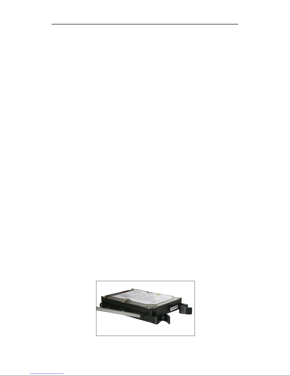
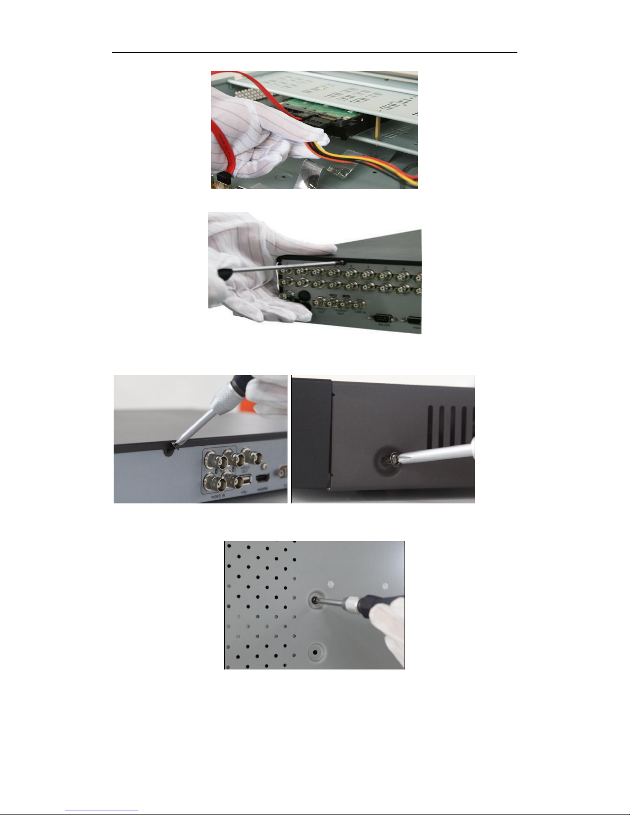
Steps (for DS-9100/9000HFI-ST/RT/XT):
1. Fasten the hard disk mounting handle to the hard disk with screws.
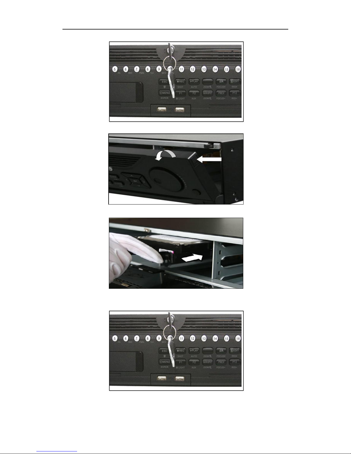
2. Insert the key and turn in clockwise direction to open the panel lock.
Page 4
Quick Operation Guide of Digital Video Recorder
2
3. Press the buttons on the panel of two sides and open the front panel.
4. Insert the hard disk along the slot until it is placed into position.
5. Repeat the above steps to install other hard disks onto the DVR. After having finished the installation of all
hard disks, close the front panel and lock it with the key again.
Page 5
Quick Operation Guide of Digital Video Recorder
3
Steps (For DS-9100/9000HWI-ST):
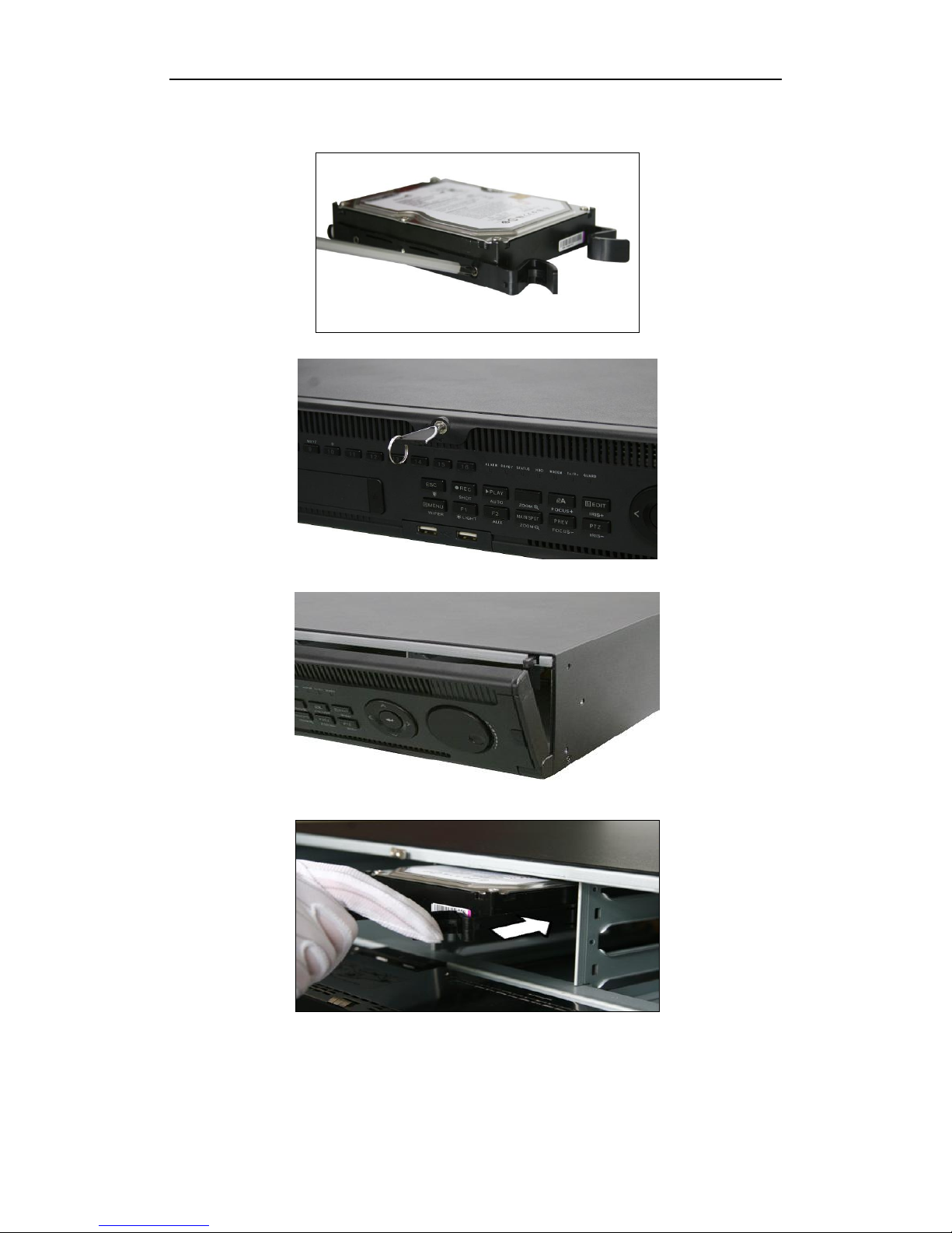
1. Fasten the hard disk mounting handle to the hard disk with screws.
2. Insert the key and turn in clockwise direction to open the panel lock.
3. Press the buttons on the panel of two sides and open the front panel.
4. Insert the hard disk along the slot until it is placed into position.
5. Repeat the above steps to install other hard disks onto the DVR. After having finished
the installation of all hard disks, close the front panel and lock it with the key again.
Page 6
Quick Operation Guide of Digital Video Recorder
4
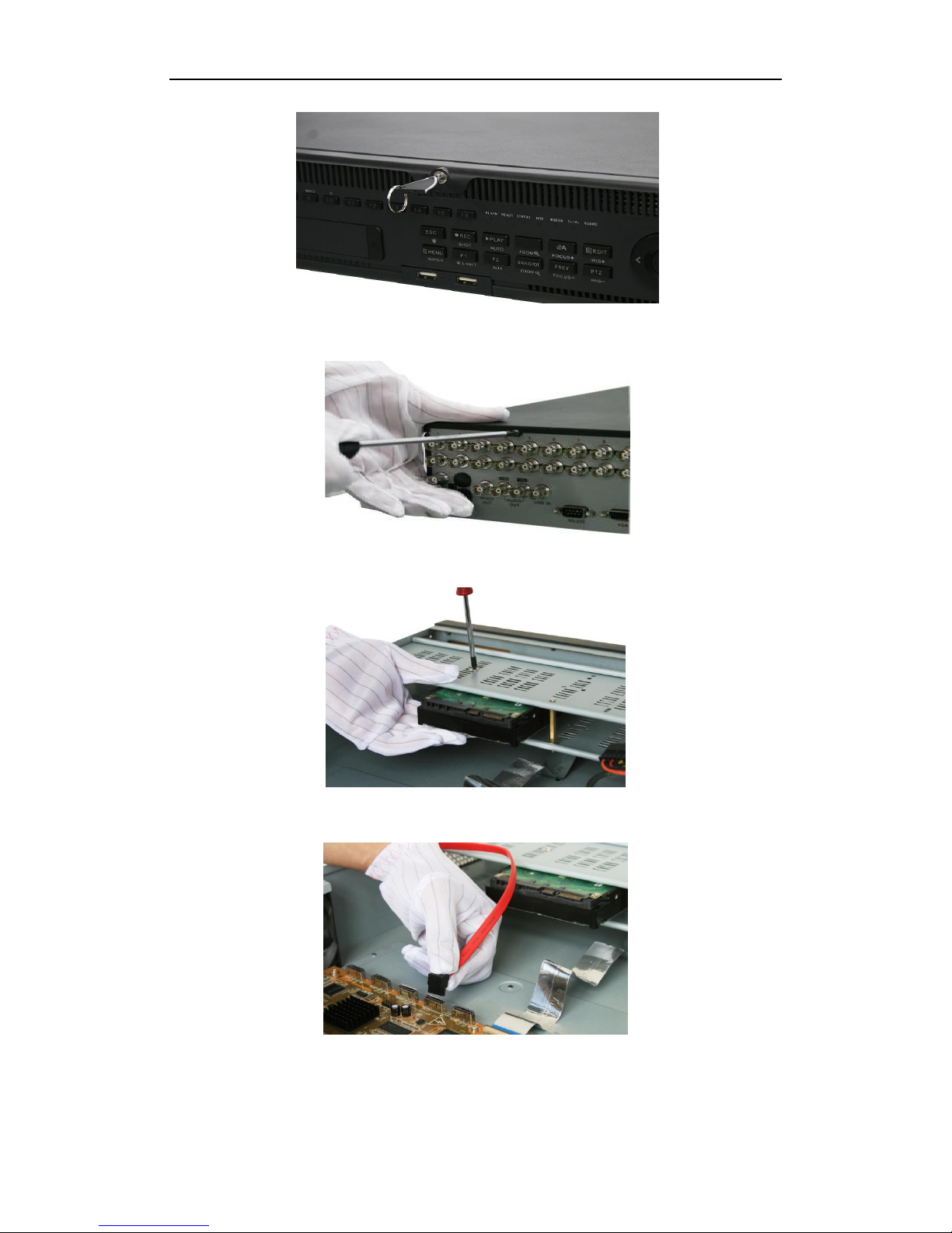
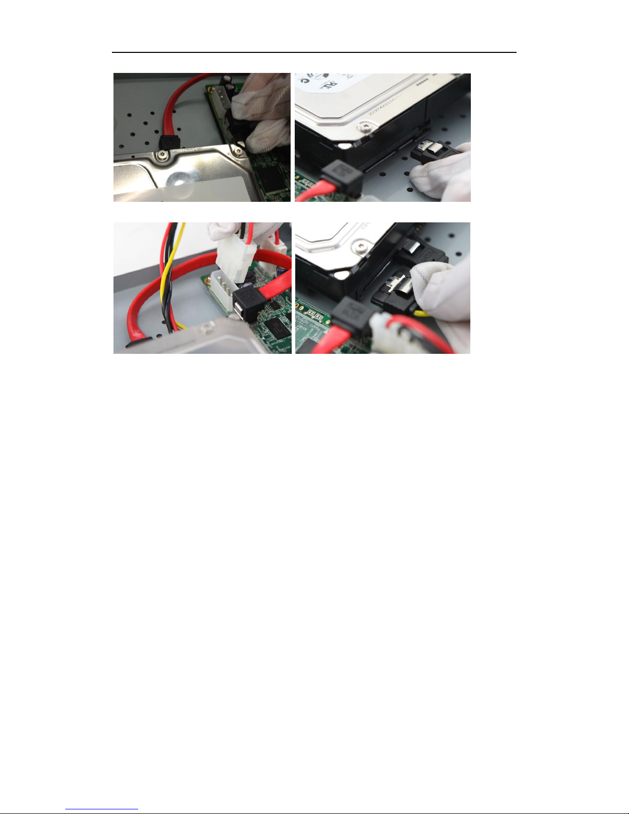
Steps (for DS-8100/8000HFI-ST & 8100/8000HWI-ST):
1. Remove the cover from the DVR by unfastening the screws on the back and side.
2. Install the HDD in the HDD rack using the provided screws. Fasten the screws on the
button to fix the HDD.
3. Connect one end of the data cable to the motherboard of DVR and the other end to the
HDD.
4. Connect the power cable to the HDD.
Page 7
Quick Operation Guide of Digital Video Recorder
5
5. Re-install the cover of the DVR and fasten screws.
Steps (for DS-7200HWI-SV & 7200HFI-SV & 7600HI-ST):
1. Remove the cover from the DVR by unfastening the screws on the back and side.
2. Install the HDD in the HDD rack using the provided screws. Fasten the screws on the
bottom to fix the HDD.
3. Connect the HDD to the motherboard of the DVR with the included data cable.
Page 8
Quick Operation Guide of Digital Video Recorder
6
4. Connect the power cable to the HDD.
5. Re-install the cover of the DVR and fasten screws.
Page 9
Quick Operation Guide of Digital Video Recorder
7
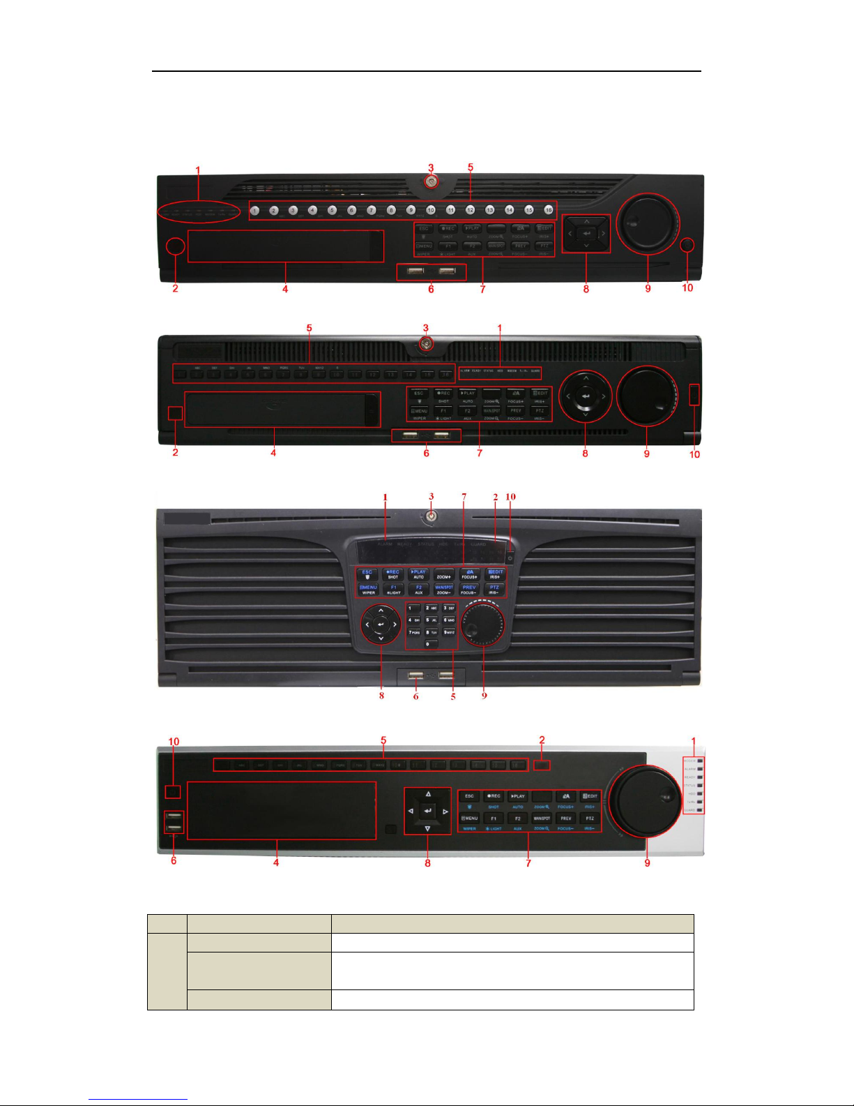
Front Panel
DS-9100/9000HFI-ST & DS-9100/9000HFI-RT
DS-9100/9000HWI-ST
DS-9100/9000HFI-XT
DS-8100/8000HFI-ST & DS-8100/8000HWI-ST
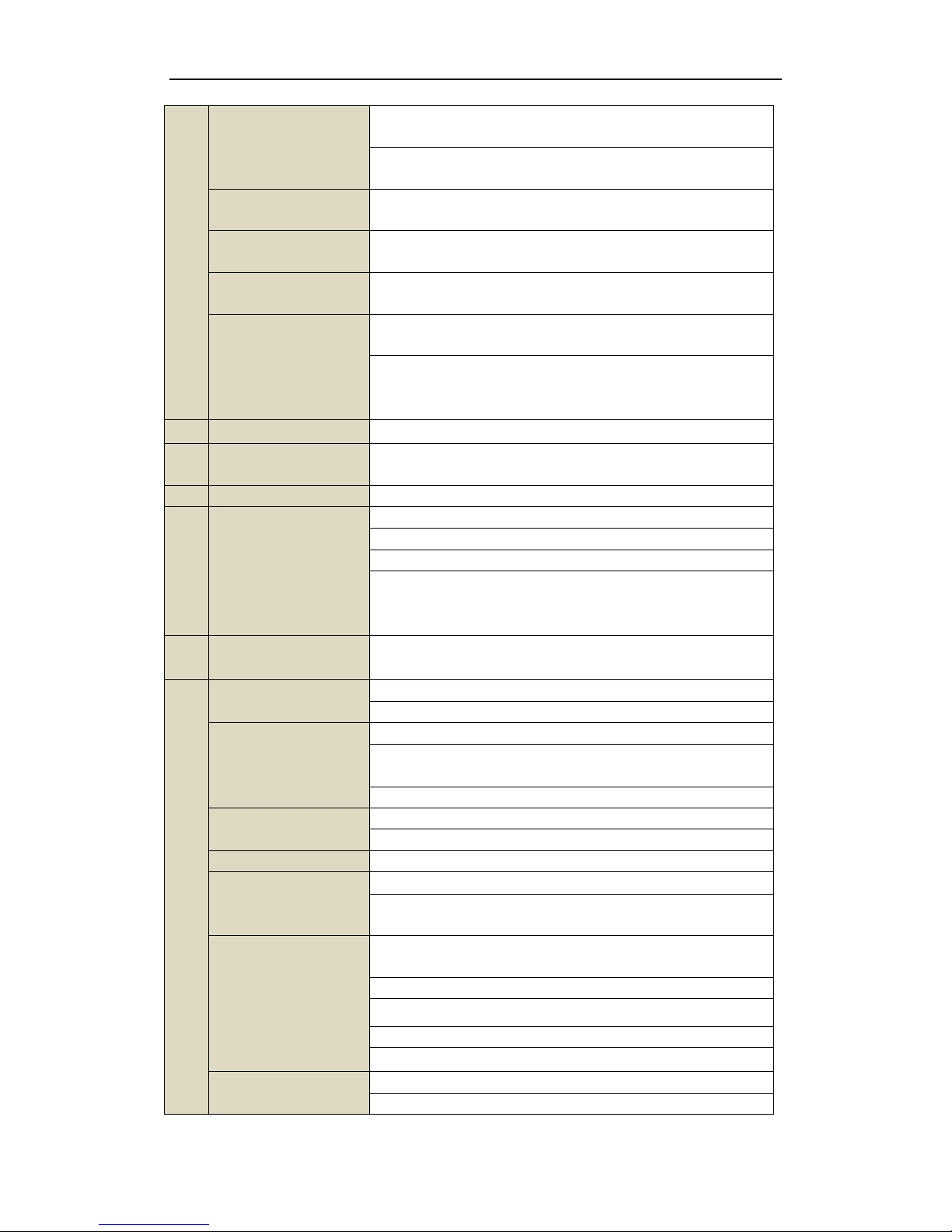
No.
Name
Function Description
1
ALARM
Alarm indicator turns red when a sensor alarm is detected.
READY
Ready indicator is normally blue, indicating that the device is functioning
properly.
STATUS
Status indicator turns blue when device is controlled by an IR remote (if
Page 10
Quick Operation Guide of Digital Video Recorder
8
the device ID# is 255, the indicator is off when the device is controlled
by an IR remote).
Indicator turns red when controlled by a keyboard and purple when IR
remote and keyboard is used at the same time.
HDD
HDD indicator blinks red when data is being read from or written to
HDD.
MODEM (Not supported
by 9100/9000HFI-XT)
Reserved for future usage.
TX/RX
TX/RX indictor blinks blue when network connection is functioning
properly.
GUARD
Guard indicator turns blue when the device is in armed status; at this
time, an alarm is enabled when an event is detected.
The indicator turns off when the device is unarmed. The arm/disarm
status can be changed by pressing and holding on the ESC button for
more than 3 seconds in live view mode.
2
IR Receiver
Receiver for IR remote
3
Front Panel Lock
(for DS-9100/9000 series)
You can lock or unlock the panel by the key.
4
DVD-R/W
Slot for DVD-R/W. (Optional for DS-9100/9000HFI-RT)
5
Alphanumeric Buttons
Switch to the corresponding channel in Live view or PTZ Control mode.
Input numbers and characters in Edit mode.
Switch channels in All-day Playback mode.
The light of the button is blue when the corresponding channel is
recording; it is red when the channel is in network transmission status; it
is pink when the channel is recording and transmitting.
6
USB Interfaces
Universal Serial Bus (USB) ports for additional devices such as USB
mouse and USB Hard Disk Drive (HDD).
7
ESC
Back to the previous menu.
Press for arming/disarming the device in Live View mode.
REC/SHOT
Enter the Manual Record setting menu.
In PTZ control settings, press the button and then you can call a PTZ
preset by pressing Numeric button.
It is also used to turn audio on/off in the Playback mode.
PLAY/AUTO
The button is used to enter the Playback mode.
It is also used to auto scan in the PTZ Control menu.
ZOOM+
Zoom in the PTZ camera in the PTZ Control setting.
A/FOCUS+
Adjust focus in the PTZ Control menu.
It is also used to switch input methods (upper and lowercase alphabet,
symbols and numeric input).
EDIT/IRIS+
Edit text fields. When editing text fields, it will also function as a
Backspace button to delete the character in front of the cursor.
On checkbox fields, pressing the button will tick the checkbox.
In PTZ Control mode, the button adjusts the iris of the camera.
In Playback mode, it can be used to generate video clips for backup.
Enter/exit the folder of USB device and eSATA HDD.
MAIN/SPOT/ZOOM-
Switch main and spot output.
In PTZ Control mode, it can be used to zoom out the image.
Page 11
Quick Operation Guide of Digital Video Recorder
9
F1/ LIGHT
Select all items on the list when used in a list field.
In PTZ Control mode, it will turn on/off PTZ light (if applicable).
In Playback mode, it is used to switch play and reverse play.
F2/ AUX
Cycle through tab pages.
In synchronous playback mode, it is used to switch channels.
MENU/WIPER
Press the button will help you return to the Main menu (after successful
login).
Press and hold the button for 5 seconds will turn off audible key beep.
In PTZ Control mode, the MENU/WIPER button will start wiper (if
applicable).
In Playback mode, it is used to show/hide the control toolbar.
PREV/FOCUS-
Switch single screen and multi-screen mode.
In PTZ Control mode, it is used to adjust the focus in conjunction with
the A/FOCUS+ button.
PTZ/IRIS-
Enter the PTZ Control mode.
In the PTZ Control mode, it is used to adjust the iris of the PTZ camera.
8
DIRECTION
The DIRECTION buttons are used to navigate between different fields
and items in menus.
In the Playback mode, the Up and Down button is used to speed up and
slow down recorded video. The Left and Right button will select the next
and previous record files.
In Live View mode, these buttons can be used to cycle through channels.
In PTZ control mode, it can control the movement of the PTZ camera.
ENTER
The ENTER button is used to confirm selection in any of the menu
modes.
It can also be used to tick checkbox fields.
In Playback mode, it can be used to play or pause the video.
In single-frame Playback mode, pressing the button will advance the
video by a single frame.
In Auto-switch mode, it can be used to stop /start auto switch.
9
JOG SHUTTLE Control
Move the active selection in a menu. It will move the selection up and
down.
In Live View mode, it can be used to cycle through different channels.
In the Playback mode: For DS-9100/9000HFI-ST/RT/XT (HWI-ST)
series, the ring is used to jump 30s forward/backward in video files. For
DS-8100/8000HFI-ST & 8100/8000HWI-ST series, the outer ring is used
to speed up or slow down the record files and the inner ring is used to
jump 30s forward/backward in records files.
In PTZ control mode, it can control the movement of the PTZ camera.
10
POWER ON/OFF
Power on/off switch.
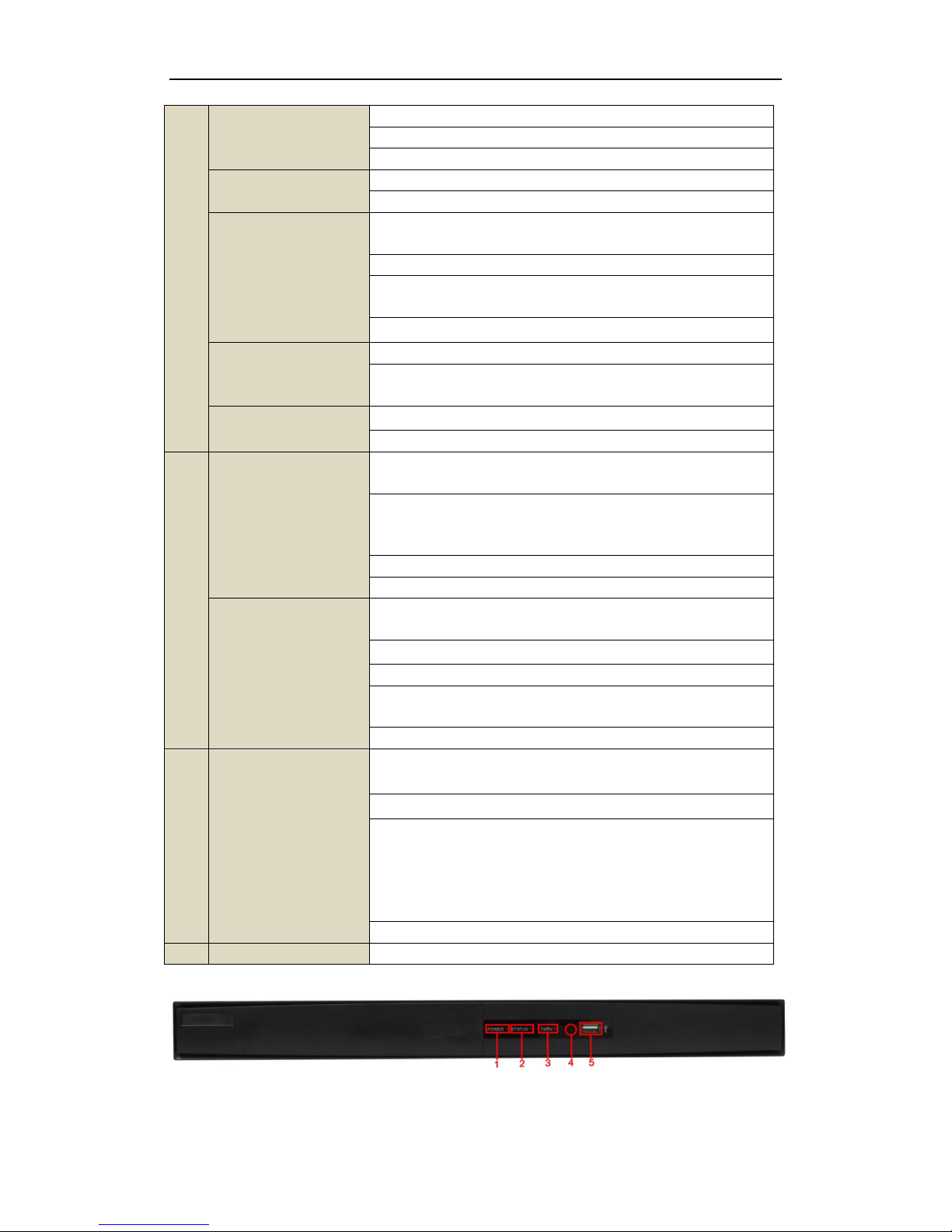
DS-7200HWI-SV & DS-7200HFI-SV & DS-7600HI-ST
Page 12

Quick Operation Guide of Digital Video Recorder
10
No.
Name
Function Description
1
POWER
POWER indicator turns green when DVR is powered up.
2
STATUS
STATUS indicator lights in red when data is being read from or written to
HDD.
3
Tx/Rx
Tx/Rx indictor blinks green when network connection is functioning properly.
4
IR Receiver
Receiver for IR remote.
5
USB Interface
Connects USB mouse or USB flash memory devices.
Page 13
Quick Operation Guide of Digital Video Recorder
11
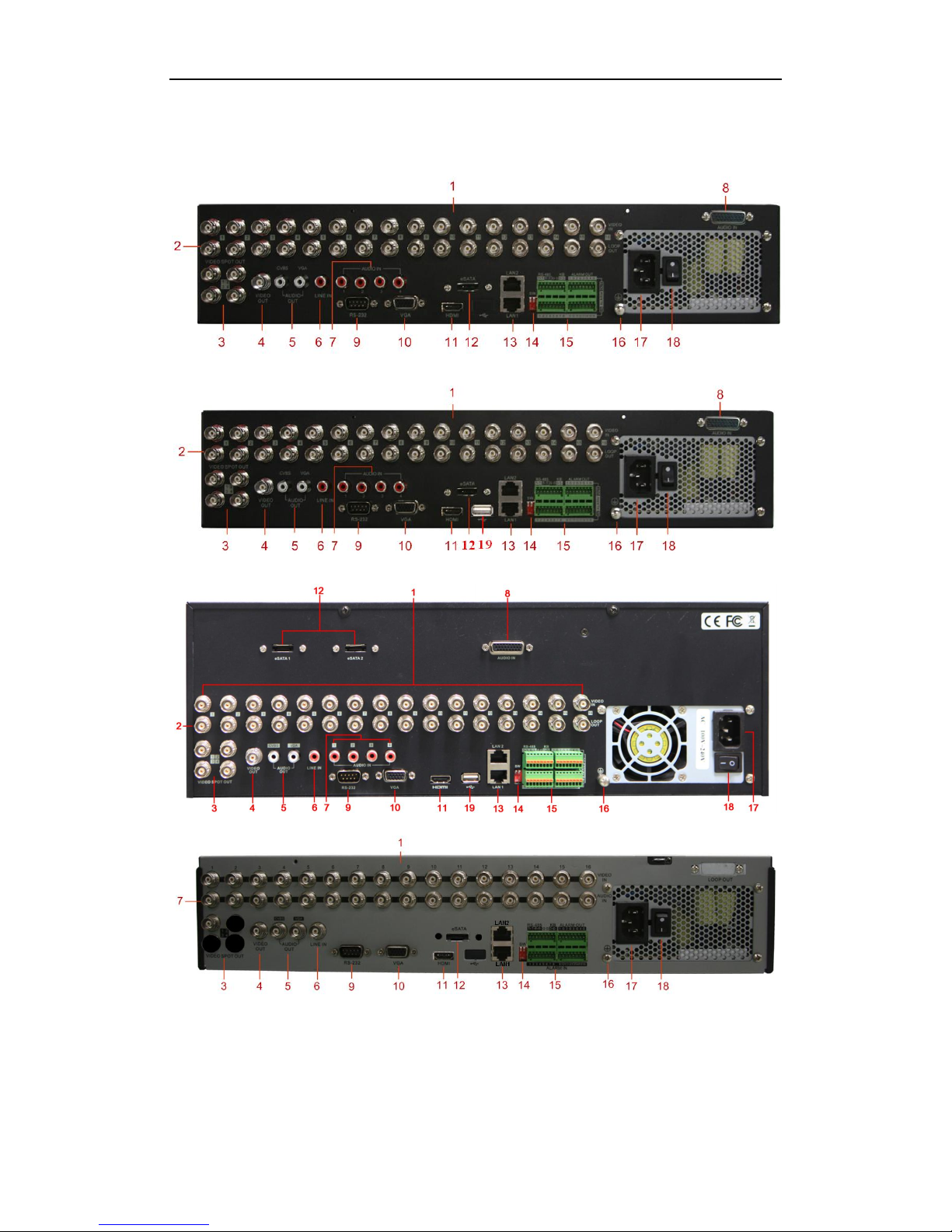
Rear Panel
DS-9100/9000HFI-ST
DS-9100/9000HWI-ST & DS-9100/9000HFI-RT
DS-9100/9000HFI-XT
DS-8100/8000HFI-ST
Page 14
Quick Operation Guide of Digital Video Recorder
12
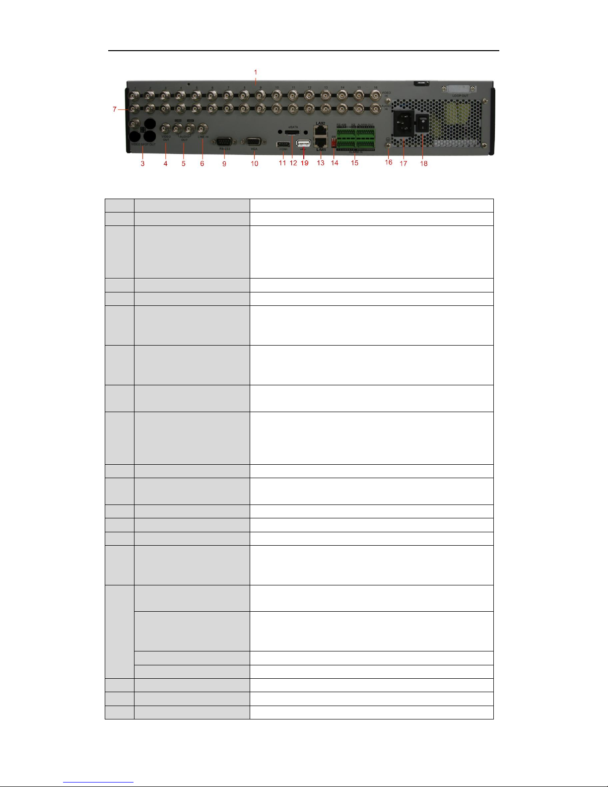
DS-8100/8000HWI-ST
No.
Item
Description
1
VIDEO IN
BNC connector for analog video input.
2
LOOP OUT
(for
DS-9100/9000HFI-ST/RT/XT
& 9100/9000HWI-ST series)
BNC connector for video loop output.
3
VIDEO SPOT OUT
BNC connector for video output.
4
VIDEO OUT
BNC connector for video output.
5
AUDIO OUT
RCA (for DS-9100/9000HFI-ST/RT/XT & 9100/9000HWI-ST) /
BNC (for DS-8100/8000HFI-ST (HWI-ST)) connector for audio
output. This connector is synchronized with VIDEO OUT.
6
LINE IN
RCA (for DS-9100/9000HFI-ST/RT/XT & 9100/9000HWI-ST) /
BNC (for DS-8100/8000HFI-ST (HWI-ST)) connector for two-way
audio.
7
AUDIO IN
RCA (for DS-9100/9000HFI-ST/RT/XT & 9100/9000HWI-ST) /
BNC (for DS-8100/8000-ST) connector for audio input.
8
AUDIO IN
(for
DS-9100/9000HFI-ST/RT/XT
& 9100/9000HWI-ST series)
DB26 connector for audio input.
9
RS-232 Interface
Connector for RS-232 devices.
10
VGA
DB9 connector for VGA output. Display local video output and
menu.
11
HDMI
HDMI video output connector.
12
eSATA (Optional)
Connects external SATA HDD, DVD-R/W.
13
LAN Interface
Network interface.
14
Termination Switch
RS-485 termination switch.
Up position is not terminated.
Down position is terminated with 120Ω resistance.
15
RS-485 Interface
Connector for RS-485 devices. T+ and T- pin connects to R+ and Rpin of PTZ receiver respectively.
Controller Port
D+, D- pin connects to Ta, Tb pin of controller. For cascading
devices, the first DVR’s D+, D- pin should be connected with the
D+, D- pin of the next DVR.
ALARM IN
Connector for alarm input.
ALARM OUT
Connector for alarm output.
16
GROUND
Ground (needs to be connected when DVR starts up).
17
AC 100V ~ 240V
AC 100V ~ 240V power supply.
18
POWER
Switch for turning on/off the device.
Page 15
Quick Operation Guide of Digital Video Recorder
13
19
USB
Universal Serial Bus (USB) ports for additional devices such as USB
Hard Disk Drive (HDD).
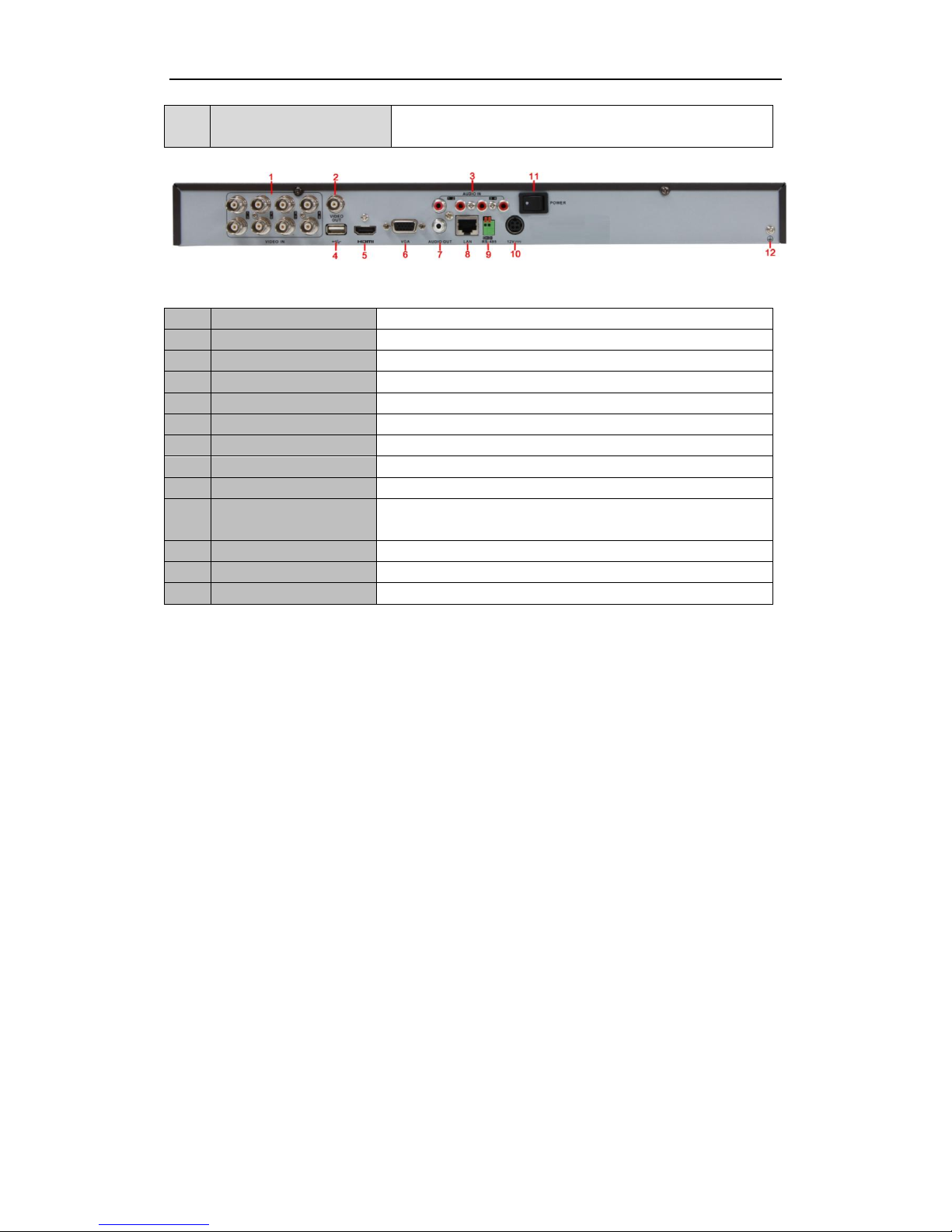
DS-7200HWI-SV & DS-7200HFI-SV & DS-7600HI-ST
No.
Item
Description
1
VIDEO IN
BNC connector for analog video input.
2
VIDEO OUT
BNC connector for video output.
3
AUDIO IN
RCA connector for audio input.
4
USB Interface
Connects USB mouse or USB flash memory devices.
5
HDMI
HDMI video output.
6
VGA
DB15 connector for VGA output. Display local video output and menu.
7
AUDIO OUT
RCA connector for audio output.
8
LAN Interface
Network interface.
9
RS-485 Interface
Connector for RS-485 devices. Connect the D+ and D- terminals to R+
and R- of PTZ receiver respectively.
10
12V
12 VDC power supply.
11
POWER
Switch for turning on/off the device.
12
GND
Ground (needs to be connected when DVR starts up).
Page 16
Quick Operation Guide of Digital Video Recorder
14
Peripheral Connections
Connecting to Alarm Input / Output Device
Note: Alarm connection is not supported by the DS-7200HFI/HWI-SV & DS-7600HI-ST series.
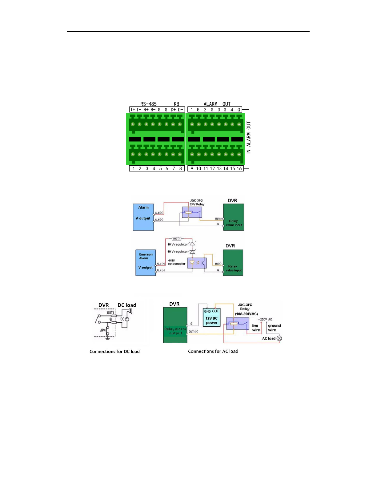
The alarm input/output interface of the DVR is shown as below:
The alarm input is an open/closed relay. If the input is not an open/closed relay, follow the connection diagram
below:
To connect to the alarm output (AC or DC load), use the following diagram:
For DC load, JP4 can be used within the limit of 12V/1A safely.
If the device is connected to an AC load, JP4 should be left open. Use an external relay for safety (as shown in the
figure above).
There are 4 jumpers (JP1, JP2, JP3, and JP4) on the motherboard, each corresponding with one alarm output. By
default, jumpers are connected. To connect an AC load, jumpers should be removed.
Note: An external relay is needed to prevent electric shock when connecting to an AC load.
Page 17
Quick Operation Guide of Digital Video Recorder
15
Alarm Connection
To connect alarm devices to the DVR:
1. Disconnect pluggable block from the ALARM IN /ALARM OUT terminal block.
2. Press and hold the orange part of the pluggable block; insert signal cables into slots and release the orange part.
Ensure signal cables are in tight.
3. Connect pluggable block back into terminal block.
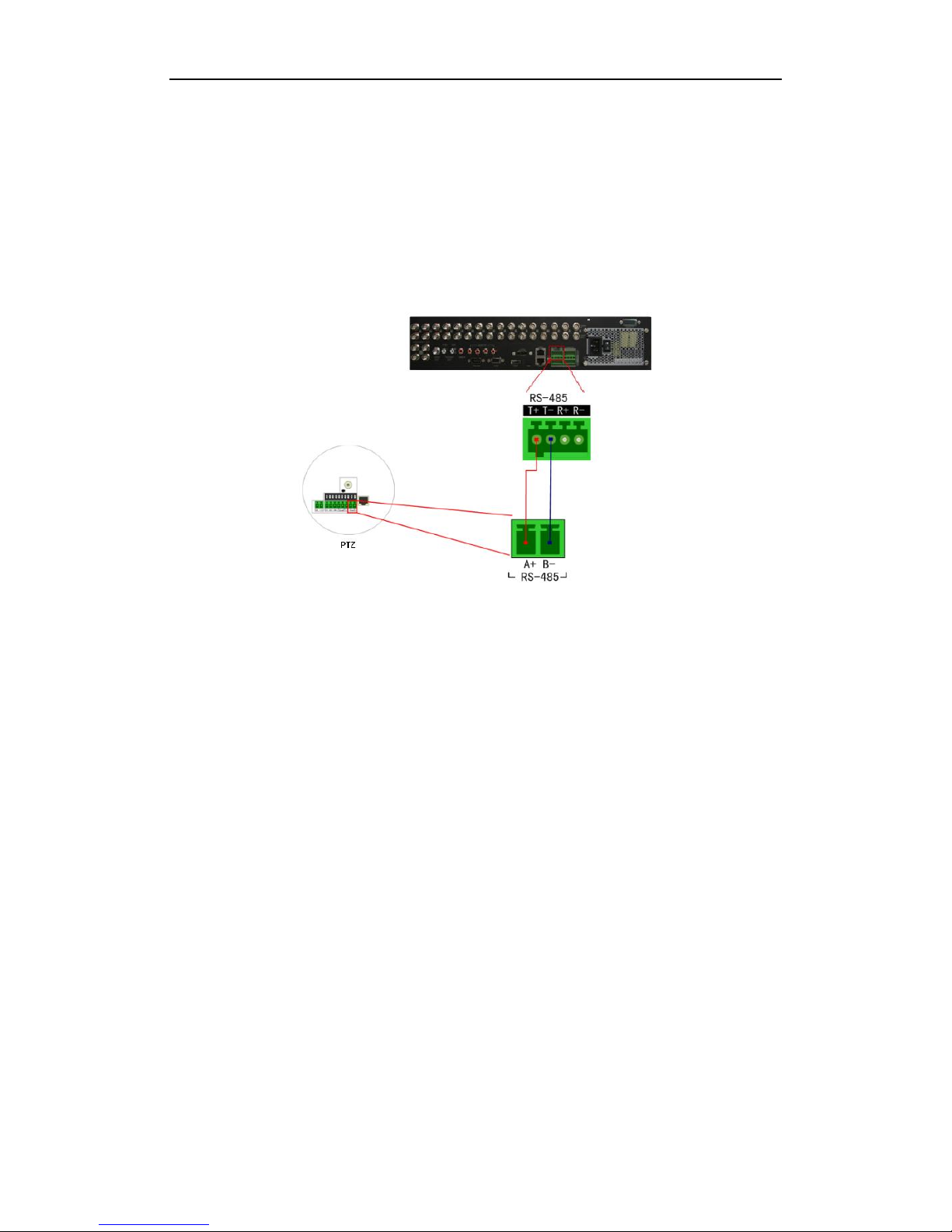
RS-485 Connection
To connect RS-485 devices to the DVR:
1. Disconnect pluggable block from the RS-485 terminal block.
2. Press and hold the orange part of the pluggable block; insert signal cables into slots and release the orange
part. Ensure signal cables are in tight.
3. Connect pluggable block back into terminal block.
Note: Make sure the pan/tilt receiver unit is connected to the T+ and T- of the DVR. Here we take the RS-485
connection of the DS-9100/9000HFI-ST as an example.
Page 18
Quick Operation Guide of Digital Video Recorder
16
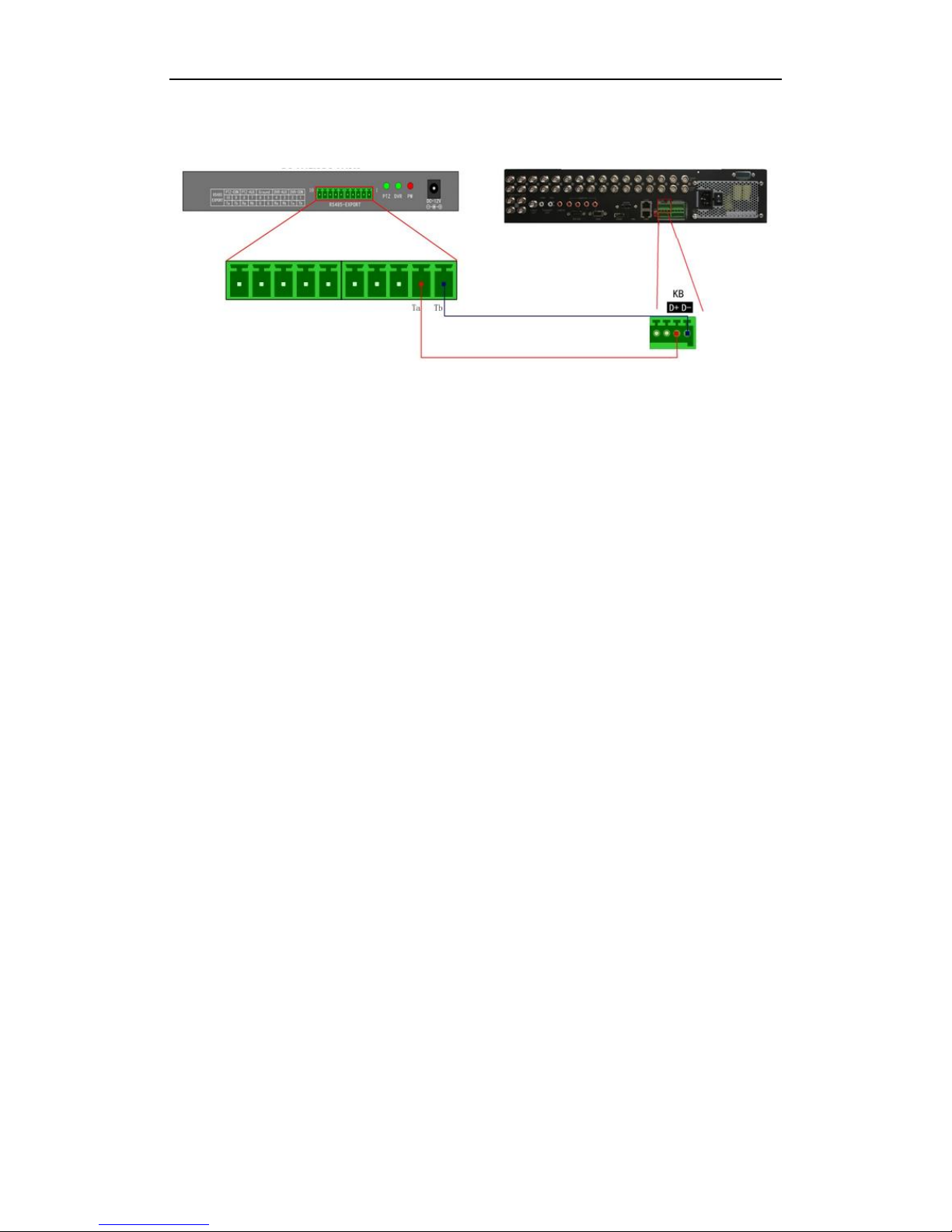
Controller Connection
Note: Controller connection is not supported by the DS-7200HFI/HWI-SV & DS-7600HI-ST series.
To connect a controller to the DVR:
1. Disconnect pluggable block from the KB terminal block.
2. Press and hold the orange part of the pluggable block; insert signal cables into slots and release the orange
part. Ensure signal cables are in tight.
3. Connect Ta on controller to D+ on terminal block and Tb on controller to D- on terminal block. Fasten stop
screws.
4. Connect pluggable block back into terminal block.
Note: Make sure both the controller and DVR are grounded. Here we take the controller connection of the
DS-9100/9000HFI-ST as an example.
Page 19
Quick Operation Guide of Digital Video Recorder
17
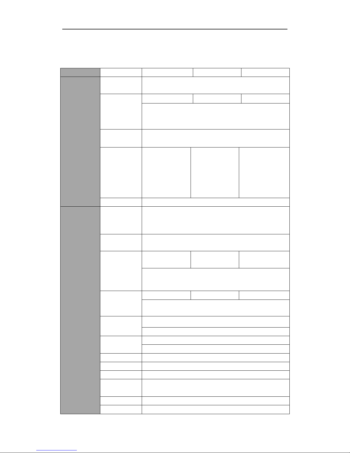
Specifications
Table 1 Specifications for DS-9100HFI-ST
Model
DS-9104HFI-ST
DS-9108HFI-ST
DS-9116HFI-ST
Video/Audio
input
Video
compression
H.264
Analog video
input
4-ch
8-ch
16-ch
BNC (1.0 Vp-p, 75 Ω)
PAL / NTSC self-adaptive
Audio
compression
OggVorbis
Audio input
4-ch,
RCA (2.0 Vp-p, 1
KΩ)
8-ch,
Audio 1-4:
RCA (2.0 Vp-p, 1
KΩ)
Audio 5-8: DB26
connector
16-ch,
Audio 1-4:
RCA (2.0 Vp-p, 1
KΩ)
Audio 5-16: DB26
connector
Two-way audio
1-ch, RCA (2.0 Vp-p, 1 KΩ)
Video/Audio
output
HDMI output
1920 × 1080 / 60 Hz (1080P), 1920 × 1080 / 50 Hz (1080P), 1600 ×
1200 / 60 Hz, 1280 × 1024 / 60 Hz, 1280 × 720 / 60 Hz, 1024 × 768 / 60
Hz
VGA output
1920 × 1080 / 60 Hz (1080P),1600 × 1200 / 60 Hz,1280 × 1024 / 60 Hz,
1280 × 720 / 60 Hz, 1024 × 768 / 60 Hz
CVBS output
2-ch (1 Main output +
1 Spot output)
5-ch (1 Main output
+ 4 Spot outputs)
5-ch (1 Main output +
4 Spot outputs)
BNC (1.0 Vp-p, 75 Ω),
resolution: PAL: 704 × 576, NTSC: 704 × 480
Video loop out
4-ch
8-ch
16-ch
BNC (1.0 Vp-p, 75 Ω)
Encoding
resolution
Main stream: 4CIF / 2CIF / CIF / QCIF
Sub-stream: CIF / QCIF
Frame rate
Main stream: 25 fps (P) / 30 fps (N)
Sub-stream: 25 fps (P) / 30 fps (N)
Video bitrate
32 Kbps-8 Mbps
Audio output
2-ch, RCA (2.0 Vp-p, 1 KΩ)
Audio bitrate
16 Kbps
Dual-stream
Support
Stream type
Video, Video & Audio
Playback
4CIF / 2CIF / CIF / QCIF
Page 20

Quick Operation Guide of Digital Video Recorder
18
resolution
Synchronous
playback
4-ch
8-ch
16-ch
Hard disk
SATA
8 SATA interfaces for 4 HDDs + 1 DVD-R/W (default), or 8HDDs
eSATA
1 eSATA interface
Capacity
Up to 4 TB capacity for each disk
External
interface
Network
interface
2; 10M / 100M / 1000M self-adaptive Ethernet interface
Serial interface
RS-232, RS-485, Keyboard
USB port
2 × USB2.0
Alarm in / out
4 / 2
16 / 4
16 / 4
General
Power supply
100 ~ 240 VAC, 6.3 A, 50~60 Hz
Consumption
(without hard
disk or
DVD-R/W)
Max. 35 W
Max. 40 W
Max. 45 W
Working
temperature
-10 ºC ~ +55 ºC (14 ºF ~ 131 ºF)
Working
humidity
10% ~ 90%
Chassis
19-inch rack-mounted 2U chassis
Dimensions
(W × D × H)
445 × 470 × 90 mm (17.5 × 18.5 × 3.5 in)
Weight
Approx. 8 kg / 17.6lb (without hard disk or DVD-R/W)
Page 21

Quick Operation Guide of Digital Video Recorder
19
Table 2 Specifications for DS-9000HFI-ST
Model
DS-9004HFI-ST
DS-9008HFI-ST
DS-9016HFI-ST
Video/Audio
input
Video
compression
H.264
Analog video
input
4-ch
8-ch
16-ch
BNC (1.0 Vp-p, 75 Ω),
PAL / NTSC self-adaptive
IP video input
8-ch
16-ch
32-ch
Composite
video input
Up to 8-ch
(Analog video + IP
video)
Up to 16-ch (Analog
video + IP video )
Up to 32-ch (Analog
video + IP video )
Audio
compression
OggVorbis
Audio input
4-ch,
RCA (2.0 Vp-p, 1
KΩ)
8-ch,
Audio 1-4:
RCA (2.0 Vp-p, 1
KΩ)
Audio 5-8: DB26
connector
16-ch,
Audio 1-4:
RCA (2.0 Vp-p, 1 KΩ)
Audio 5-16: DB26
connector
Two-way audio
1-ch, RCA (2.0 Vp-p, 1 KΩ)
Video/Audio
output
HDMI output
1920 × 1080 / 60 Hz (1080P), 1920 × 1080 / 50 Hz (1080P), 1600 ×
1200 / 60 Hz, 1280 × 1024 / 60 Hz, 1280 × 720 / 60 Hz, 1024 × 768 / 60
Hz
VGA output
1920 × 1080 / 60 Hz (1080P), 1600 × 1200 / 60 Hz,1280 × 1024 / 60 Hz,
1280 × 720 / 60 Hz, 1024 × 768 / 60 Hz
CVBS output
2-ch (1 Main output +
1 Spot output)
5-ch (1 Main output
+ 4 Spot outputs)
5-ch (1 Main output +
4 Spot outputs)
BNC (1.0 Vp-p, 75 Ω),
resolution: PAL: 704 × 576, NTSC: 704 × 480
Video loop out
4-ch
8-ch
16-ch
BNC (1.0 Vp-p, 75 Ω)
Encoding
resolution
Main stream: 4CIF / 2CIF / CIF / QCIF
Sub-stream: CIF / QCIF
Frame rate
Main stream: 25 fps (P) / 30 fps (N)
Sub-stream: 25 fps (P) / 30 fps (N)
Video bitrate
32 Kbps ~ 8 Mbps
Audio output
2-ch, RCA (2.0 Vp-p, 1 KΩ)
Audio bitrate
16 Kbps
Page 22

Quick Operation Guide of Digital Video Recorder
20
Dual-stream
Support
Stream type
Video, Video & Audio
Playback
resolution
5Megapixels /3Megapixels / 1080P / UXGA / 720P / 4CIF / VGA /
DCIF / 2CIF / CIF / QCIF
Synchronous
playback
8-ch
16-ch
16-ch
Hard disk
SATA
8 SATA interfaces for 4 HDDs + 1 DVD-R/W (default), or 8HDDs
eSATA
1 eSATA interface
Capacity
Up to 4 TB capacity for each disk
External
interface
Network
interface
2; 10M / 100M / 1000M self-adaptive Ethernet interface
Serial interface
RS-232, RS-485, Keyboard
USB port
2 × USB2.0
Alarm in / out
4 / 2
16 / 4
16 / 4
General
Power supply
100 ~ 240 VAC, 6.3 A, 50 ~ 60 Hz
Consumption
(without hard
disk or
DVD-R/W)
Max. 35 W
Max. 40 W
Max. 45 W
Working
temperature
-10 ºC ~ +55 ºC (14 ºF ~ 131 ºF)
Working
humidity
10%~90%
Chassis
19-inch rack-mounted 2U chassis
Dimensions
(W × D × H)
445 × 470 × 90 mm (17.5 × 18.5 × 3.5 in)
Weight
Approx. 8 kg / 17.6 lb (without hard disk or DVD-R/W)
Page 23

Quick Operation Guide of Digital Video Recorder
21
Table 3 Specifications for DS-8100HFI-ST
Model
DS-8104HFI-ST
DS-8108HFI-ST
DS-8116HFI-ST
Video/Audio
input
Video
compression
H.264
Analog video
input
4-ch
8-ch
16-ch
BNC (1.0 Vp-p, 75 Ω),
PAL / NTSC self-adaptive
Audio
compression
OggVorbis
Audio input
4-ch
8-ch
16-ch
BNC (2.0 Vp-p, 1 KΩ)
Two-way audio
1-ch, BNC (2.0 Vp-p, 1 KΩ)
Video/Audio
output
HDMI output
1920 × 1080 / 60 Hz (1080P), 1920 × 1080 / 50 Hz (1080P),1600 × 1200
/ 60 Hz, 1280 × 1024 / 60 Hz, 1280 × 720 / 60 Hz, 1024 × 768 / 60 Hz
VGA output
1920 × 1080 / 60 Hz (1080P), 1600 × 1200 / 60 Hz, 1280 × 1024 / 60
Hz, 1280 × 720 / 60 Hz, 1024 × 768 / 60 Hz
CVBS output
2-ch (1 Main output + 1 Spot output )
BNC (1.0 Vp-p, 75 Ω),
resolution: PAL: 704 × 576, NTSC: 704 × 480
Video loop out
Optional
Encoding
resolution
Main stream: 4CIF / 2CIF / CIF / QCIF
Sub-stream: CIF / QCIF
Frame rate
Main stream: 25 fps (P) / 30 fps (N)
Sub-stream: 25 fps (P) / 30 fps (N)
Video bitrate
32 Kbps ~ 8 Mbps
Audio output
2-ch, BNC (Linear, 600 Ω)
Audio bitrate
16 Kbps
Dual-stream
Support
Stream type
Video, Video & Audio
Playback
resolution
4CIF / 2CIF / CIF / QCIF
Synchronous
playback
4-ch
8-ch
16-ch
Hard disk
SATA
8 SATA interfaces for 4 HDDs + 1 DVD-R/W (default), or 8HDDs
eSATA
1 eSATA interface
Capacity
Up to 4 TB capacity for each disk
External
interface
Network
interface
2; 10M / 100M / 1000M self-adaptive Ethernet interface
Page 24

Quick Operation Guide of Digital Video Recorder
22
Serial interface
RS-232, RS-485, Keyboard
USB port
2 × USB2.0
Alarm in / out
4 / 2
16 / 4
16 / 4
General
Power supply
100 ~ 240 VAC, 6.3 A, 50 ~ 60 Hz
Consumption
(without hard
disk or
DVD-R/W)
Max. 35 W
Max. 40 W
Max. 45 W
Working
temperature
-10 ºC ~ +55 ºC (14 ºF ~ 131 ºF)
Working
humidity
10% ~ 90%
Chassis
19-inch rack-mounted 2U chassis
Dimensions
(W × D × H)
445 × 470 × 90 mm (17.5 × 18.5 × 3.5 in)
Weight
Approx. 8 kg / 17.6 lb (without hard disk or DVD-R/W)
Page 25

Quick Operation Guide of Digital Video Recorder
23
Table 4 Specifications for DS-8000HFI-ST
Model
DS-8004HFI-ST
DS-8008HFI-ST
DS-8016HFI-ST
Video/Audio
input
Video
compression
H.264
Analog video
input
4-ch
8-ch
16-ch
BNC (1.0 Vp-p, 75 Ω),
PAL / NTSC self-adaptive
IP video input
8-ch
16-ch
32-ch
Composite
video input
Up to 8-ch
(Analog video + IP
video)
Up to 16-ch (Analog
video + IP video)
Up to 32-ch (Analog
video + IP video)
Audio
compression
OggVorbis
Audio input
4-ch
8-ch
16-ch
BNC (2.0 Vp-p, 1 KΩ)
Two-way audio
1-ch, BNC (2.0 Vp-p, 1 KΩ)
Video/Audio
output
HDMI output
1920 × 1080 / 60 Hz (1080P),1920 × 1080 / 50 Hz (1080P), 1600 ×
1200 / 60 Hz, 1280 × 1024 / 60 Hz, 1280 × 720 / 60 Hz, 1024 × 768 / 60
Hz
VGA output
1920 × 1080 / 60 Hz (1080P),1600 × 1200 / 60 Hz, 1280 × 1024 / 60
Hz, 1280 × 720 / 60 Hz, 1024 × 768 / 60 Hz
CVBS output
2-ch (1 Main output + 1 Spot output)
BNC (1.0 Vp-p, 75 Ω),
resolution: PAL: 704 × 576, NTSC: 704 × 480
Video loop out
Optional
Encoding
resolution
Main stream: 4CIF / 2CIF / CIF / QCIF
Sub-stream: CIF / QCIF
Frame rate
Main stream: 25 fps (P) / 30 fps (N)
Sub-stream: 25 fps (P) / 30 fps (N)
Video bitrate
32 Kbps ~ 8 Mbps
Audio output
2-ch, BNC (Linear, 600 Ω)
Audio bitrate
16 Kbps
Dual-stream
Support
Stream type
Video, Video & Audio
Playback
resolution
5Megapixels / 3Megapixels / 1080P / UXGA / 720P / 4CIF / VGA /
DCIF / 2CIF / CIF / QCIF
Page 26

Quick Operation Guide of Digital Video Recorder
24
Synchronous
playback
8-ch
16-ch
16-ch
Hard disk
SATA
8 SATA interfaces for 4 HDDs + 1 DVD-R/W (default), or 8HDDs
eSATA
1 eSATA interface
Capacity
Up to 4 TB capacity for each disk
External
interface
Network
interface
2; 10M / 100M / 1000M self-adapter Ethernet interface
Serial interface
RS-232, RS-485, Keyboard
USB port
2 × USB2.0
Alarm in / out
4 / 2
16 / 4
16 / 4
General
Power supply
100 ~ 240 VAC, 6.3 A, 50 ~ 60 Hz
Consumption
(without hard
disk or
DVD-R/W)
Max. 35 W
Max. 40 W
Max. 45 W
Working
temperature
-10 ºC ~ +55 ºC (14 ºF ~ 131 ºF)
Working
humidity
10% ~ 90%
Chassis
19-inch rack-mounted 2U chassis
Dimensions
(W × D × H)
445 × 470 × 90 mm (17.5 × 18.5 × 3.5 in)
Weight
Approx. 8 kg / 17.6 lb (without hard disk or DVD-R/W)
Page 27

Quick Operation Guide of Digital Video Recorder
25
Table 5 Specifications for DS-9100HFI-RT
Model
DS-9104HFI-RT
DS-9108HFI-RT
DS-9116HFI-RT
Video/Audio
input
Video
compression
H.264
Analog video
input
4-ch
8-ch
16-ch
BNC (1.0 Vp-p, 75 Ω)
PAL / NTSC self-adaptive
Audio
compression
OggVorbis
Audio input
4-ch,
RCA (2.0 Vp-p, 1
KΩ)
8-ch,
Audio 1-4:
RCA (2.0 Vp-p, 1
KΩ)
Audio 5-8: DB26
connector
16-ch,
Audio 1-4:
RCA (2.0 Vp-p, 1 KΩ)
Audio 5-16: DB26
connector
Two-way audio
1-ch, RCA (2.0 Vp-p, 1 KΩ)
Video/Audio
output
HDMI output
1920 × 1080 / 60 Hz (1080P), 1920 × 1080 / 50 Hz (1080P), 1600 ×
1200 / 60 Hz, 1280 × 1024 / 60 Hz, 1280 × 720 / 60 Hz, 1024 × 768 / 60
Hz
VGA output
1920 × 1080 / 60 Hz (1080P),1600 × 1200 / 60 Hz,1280 × 1024 / 60 Hz,
1280 × 720 / 60 Hz, 1024 × 768 / 60 Hz
CVBS output
2-ch (1 Main output
+ 1 Spot output)
5-ch (1 Main output
+ 4 Spot outputs)
5-ch (1 Main output +
4 Spot outputs)
BNC (1.0 Vp-p, 75 Ω),
resolution: PAL: 704 × 576, NTSC: 704 × 480
Video loop out
4-ch
8-ch
16-ch
BNC (1.0 Vp-p, 75 Ω)
Encoding
resolution
Main stream: 4CIF / 2CIF / CIF / QCIF
Sub-stream: CIF / QCIF
Frame rate
Main stream: 25 fps (P) / 30 fps (N)
Sub-stream: 25 fps (P) / 30 fps (N)
Video bitrate
32 Kbps-2 Mbps, or user defined (Max. 8 Mbps)
Audio output
2-ch, RCA (2.0 Vp-p, 1 KΩ)
Audio bitrate
16 Kbps
Dual-stream
Support
Stream type
Video, Video & Audio
Playback
resolution
4CIF / 2CIF / CIF / QCIF
Synchronous
4-ch
8-ch
16-ch
Page 28

Quick Operation Guide of Digital Video Recorder
26
playback
Hard disk
SATA
8 SATA interfaces
eSATA
1 eSATA interface
Capacity
Up to 4 TB capacity for each disk
Disk array
Array type
RAID0, RAID1, RAID5, RAID10
Number of array
4
Number of
virtual disk
8
External
interface
Network
interface
2; 10M / 100M / 1000M self-adaptive Ethernet interface
Serial interface
RS-232, RS-485, Keyboard
USB port
3 × USB2.0
Alarm in / out
4 / 2
16 / 4
16 / 4
General
Power supply
100 ~ 240 VAC, 6.3 A, 50~60 Hz
Consumption
(without hard
disk or
DVD-R/W)
Max. 35 W
Max. 40 W
Max. 45 W
Working
temperature
-10 ºC ~+55 ºC (14 ºF ~ 131 ºF)
Working
humidity
10% ~ 90%
Chassis
19-inch rack-mounted 2U chassis
Dimensions
(W × D × H)
445 × 470 × 90 mm (17.5 × 18.5 × 3.5 in)
Weight
Approx. 8 kg / 17.6lb (without hard disk or DVD-R/W)
Page 29

Quick Operation Guide of Digital Video Recorder
27
Table 6 Specifications for DS-9000HFI-RT
Model
DS-9004HFI-RT
DS-9008HFI-RT
DS-9016HFI-RT
Video/Audio
input
Video
compression
H.264
Analog video
input
4-ch
8-ch
16-ch
BNC (1.0 Vp-p, 75 Ω),
PAL / NTSC self-adaptive
IP video input
8-ch
16-ch
32-ch
Composite
video input
Up to 8-ch
(Analog video + IP
video)
Up to 16-ch (Analog
video + IP video )
Up to 32-ch (Analog
video + IP video )
Audio
compression
OggVorbis
Audio input
4-ch,
RCA (2.0 Vp-p, 1
KΩ)
8-ch,
Audio 1-4:
RCA (2.0 Vp-p, 1
KΩ)
Audio 5-8: DB26
connector
16-ch,
Audio 1-4:
RCA (2.0 Vp-p, 1 KΩ)
Audio 5-16: DB26
connector
Two-way audio
1-ch, RCA (2.0 Vp-p, 1 KΩ)
Video/Audio
output
HDMI output
1920 × 1080 / 60 Hz (1080P), 1920 × 1080 / 50 Hz (1080P), 1600 ×
1200 / 60 Hz, 1280 × 1024 / 60 Hz, 1280 × 720 / 60 Hz, 1024 × 768 / 60
Hz
VGA output
1920 × 1080 / 60 Hz (1080P), 1600 × 1200 / 60 Hz,1280 × 1024 / 60 Hz,
1280 × 720 / 60 Hz, 1024 × 768 / 60 Hz
CVBS output
2-ch (1 Main output +
1 Spot output)
5-ch (1 Main output
+ 4 Spot outputs)
5-ch (1 Main output +
4 Spot outputs)
BNC (1.0 Vp-p, 75 Ω),
resolution: PAL: 704 × 576, NTSC: 704 × 480
Video loop out
4-ch
8-ch
16-ch
BNC (1.0 Vp-p, 75 Ω)
Encoding
resolution
Main stream: 4CIF / 2CIF / CIF / QCIF
Sub-stream: CIF / QCIF
Frame rate
Main stream: 25 fps (P) / 30 fps (N)
Sub-stream: 25 fps (P) / 30 fps (N)
Video bitrate
32 Kbps ~ 8 Mbps
Audio output
2-ch, RCA (2.0 Vp-p, 1 KΩ)
Audio bitrate
16 Kbps
Page 30

Quick Operation Guide of Digital Video Recorder
28
Dual-stream
Support
Stream type
Video, Video & Audio
Playback
resolution
5Megapixels /3Megapixels / 1080P / UXGA / 720P / 4CIF / VGA /
DCIF / 2CIF / CIF / QCIF
Synchronous
playback
8-ch
16-ch
16-ch
Hard disk
SATA
8 SATA interfaces
eSATA
1 eSATA interface
Capacity
Up to 4 TB capacity for each disk
Disk array
Array type
RAID0, RAID1, RAID5, RAID10,
Number of array
4
Number of
virtual disk
8
External
interface
Network
interface
2; 10M / 100M / 1000M self-adaptive Ethernet interface
Serial interface
RS-232, RS-485, Keyboard
USB port
3 × USB2.0
Alarm in / out
4 / 2
16 / 4
16 / 4
General
Power supply
100 ~ 240 VAC, 6.3 A, 50 ~ 60 Hz
Consumption
(without hard
disk or
DVD-R/W)
Max. 35 W
Max. 40 W
Max. 45 W
Working
temperature
-10 ºC ~ +55 ºC (14 ºF ~ 131 ºF)
Working
humidity
10%~90%
Chassis
19-inch rack-mounted 2U chassis
Dimensions
(W × D × H)
445 × 470 × 90 mm (17.5 × 18.5 × 3.5 in)
Weight
Approx. 8 kg / 17.6 lb (without hard disk or DVD-R/W)
Page 31

Quick Operation Guide of Digital Video Recorder
29
Table 7 Specifications for DS-9116HFI-XT
Model
DS-9116HFI-XT
Video/Audio
input
Video
compression
H.264
Analog video
input
16-ch
BNC (1.0 Vp-p, 75 Ω)
PAL / NTSC self-adaptive
Audio
compression
OggVorbis
Audio input
16-ch,
Audio 1-4:
RCA (2.0 Vp-p, 1 KΩ)
Audio 5-16: DB26 connector
Two-way audio
1-ch, RCA (2.0 Vp-p, 1 KΩ)
Video/Audio
output
HDMI output
1920 × 1080 / 60 Hz (1080P), 1920 × 1080 / 50 Hz (1080P), 1600 ×
1200 / 60 Hz, 1280 × 1024 / 60 Hz, 1280 × 720 / 60 Hz, 1024 × 768 / 60
Hz
VGA output
1920 × 1080 / 60 Hz (1080P),1600 × 1200 / 60 Hz,1280 × 1024 / 60 Hz,
1280 × 720 / 60 Hz, 1024 × 768 / 60 Hz
CVBS output
5-ch (1 Main output + 4 Spot outputs)
BNC (1.0 Vp-p, 75 Ω),
resolution: PAL: 704 × 576, NTSC: 704 × 480
Video loop out
16-ch
BNC (1.0 Vp-p, 75 Ω)
Encoding
resolution
Main stream: 4CIF / 2CIF / CIF / QCIF
Sub-stream: CIF / QCIF
Frame rate
Main stream: 25 fps (P) / 30 fps (N)
Sub-stream: 25 fps (P) / 30 fps (N)
Video bitrate
32 Kbps-8 Mbps
Audio output
2-ch, RCA (2.0 Vp-p, 1 KΩ)
Audio bitrate
16 Kbps
Dual-stream
Support
Stream type
Video, Video & Audio
Playback
resolution
4CIF / 2CIF / CIF / QCIF
Synchronous
playback
16-ch
Hard disk
SATA
16 SATA interfaces
Page 32

Quick Operation Guide of Digital Video Recorder
30
eSATA
2 eSATA interfaces
Capacity
Up to 4 TB capacity for each disk
External
interface
Network
interface
2; 10M / 100M / 1000M self-adaptive Ethernet interface
Serial interface
RS-232, RS-485, Keyboard
USB port
3 × USB2.0
Alarm in / out
16 / 4
General
Power supply
100 ~ 240 VAC, 6.3 A, 50~60 Hz
Consumption
(without hard
disk or
DVD-R/W)
Max. 45 W
Working
temperature
-10 ºC ~+55 ºC (14 ºF ~ 131 ºF)
Working
humidity
10% ~ 90%
Chassis
19-inch rack-mounted 3U chassis
Dimensions
(W × D × H)
445 × 496 × 146 mm (17.5 × 19.5 × 5.7 in)
Weight
Approx. 12.5 kg / 27.6 lb (without hard disk or DVD-R/W)
Page 33

Quick Operation Guide of Digital Video Recorder
31
Table 8 Specifications for DS-9016HFI-XT
Model
DS-9016HFI-XT
Video/Audio
input
Video
compression
H.264
Analog video
input
16-ch
BNC (1.0 Vp-p, 75 Ω),
PAL / NTSC self-adaptive
IP video input
32-ch
Composite
video input
Up to 32-ch (Analog video + IP video )
Audio
compression
OggVorbis
Audio input
16-ch,
Audio 1-4:
RCA (2.0 Vp-p, 1 KΩ)
Audio 5-16: DB26 connector
Two-way audio
1-ch, RCA (2.0 Vp-p, 1 KΩ)
Video/Audio
output
HDMI output
1920 × 1080 / 60 Hz (1080P), 1920 × 1080 / 50 Hz (1080P), 1600 ×
1200 / 60 Hz, 1280 × 1024 / 60 Hz, 1280 × 720 / 60 Hz, 1024 × 768 / 60
Hz
VGA output
1920 × 1080 / 60 Hz (1080P), 1600 × 1200 / 60 Hz,1280 × 1024 / 60 Hz,
1280 × 720 / 60 Hz, 1024 × 768 / 60 Hz
CVBS output
5-ch (1 Main output + 4 Spot outputs)
BNC (1.0 Vp-p, 75 Ω),
resolution: PAL: 704 × 576, NTSC: 704 × 480
Video loop out
16-ch
BNC (1.0 Vp-p, 75 Ω)
Encoding
resolution
Main stream: 4CIF / 2CIF / CIF / QCIF
Sub-stream: CIF / QCIF
Frame rate
Main stream: 25 fps (P) / 30 fps (N)
Sub-stream: 25 fps (P) / 30 fps (N)
Video bitrate
32 Kbps ~ 8 Mbps
Audio output
2-ch, RCA (2.0 Vp-p, 1 KΩ)
Audio bitrate
16 Kbps
Dual-stream
Support
Stream type
Video, Video & Audio
Page 34

Quick Operation Guide of Digital Video Recorder
32
Playback
resolution
5Megapixels /3Megapixels / 1080P / UXGA / 720P / 4CIF / VGA /
DCIF / 2CIF / CIF / QCIF
Synchronous
playback
16-ch
Hard disk
SATA
16 SATA interfaces
eSATA
2 eSATA interfaces
Capacity
Up to 4 TB capacity for each disk
External
interface
Network
interface
2; 10M / 100M / 1000M self-adaptive Ethernet interface
Serial interface
RS-232, RS-485, Keyboard
USB port
3 × USB2.0
Alarm in / out
16 / 4
General
Power supply
100 ~ 240 VAC, 6.3 A, 50 ~ 60 Hz
Consumption
(without hard
disk or
DVD-R/W)
Max. 45 W
Working
temperature
-10 ºC ~ +55 ºC (14 ºF ~ 131 ºF)
Working
humidity
10%~90%
Chassis
19-inch rack-mounted 3U chassis
Dimensions
(W × D × H)
445 × 496 × 146 mm (17.5 × 19.5 × 5.7 in )
Weight
Approx. 12.5 kg / 27.6 lb (without hard disk or DVD-R/W)
Page 35

Quick Operation Guide of Digital Video Recorder
33
Table 9 Specifications for DS-9100HWI-ST
Model
DS-9104HWI-ST
DS-9108HWI-ST
DS-9116HWI-ST
Video/Audio
input
Video
compression
H.264
Analog video
input
4-ch
8-ch
16-ch
BNC(1.0Vp-p, 75Ω)
PAL/NTSC self-adaptive
Audio
compression
OggVorbis
Audio input
4-ch,
RCA (2.0 Vp-p, 1
KΩ)
8-ch,
Audio 1-4: RCA (2.0
Vp-p, 1 KΩ)
Audio 5-8: DB26
connector
16-ch,
Audio 1-4: RCA (2.0
Vp-p, 1 KΩ)
Audio 5-16: DB26
connector
Two-way audio
1-ch, RCA (2.0 Vp-p, 1 KΩ)
Video/Audio
output
HDMI / VGA
output
1920 × 1080 / 60 Hz (1080P), 1600 × 1200 / 60 Hz, 1280 × 1024 / 60
Hz, 1280 × 720 / 60 Hz, 1024 × 768 / 60 Hz
CVBS output
2-ch (1 Main output +
1 Spot output)
5-ch (1 Main output +
4 Spot outputs)
5-ch (1 Main output
+ 4 Spot outputs)
BNC (1.0 Vp-p, 75 Ω),
resolution: PAL: 704×576, NTSC: 704×480
Video loop out
4-ch
8-ch
16-ch
BNC (1.0 Vp-p, 75 Ω)
Encoding
resolution
Main stream: WD1 / 4CIF / 2CIF / CIF / QCIF
Sub-stream: CIF / QCIF
Frame rate
Main stream: 25 fps (P) / 30 fps (N)
Sub-stream: 25 fps (P) / 30 fps (N)
Video bitrate
32 Kbps ~ 8 Mbps
Audio output
2-ch, RCA (2.0 Vp-p, 1 KΩ)
Audio bitrate
16 Kbps
Dual-stream
Support
Stream type
Video, Video & Audio
Playback
resolution
WD1 / 4CIF / 2CIF / CIF / QCIF
Synchronous
playback
4-ch
8-ch
16-ch
Hard disk
SATA
8 SATA interfaces for 4 HDDs + 1 DVD-R/W (default), or 8HDDs
eSATA
1 eSATA interface
Capacity
Up to 4TB capacity for each disk
External
Network
2; 10M/100M/1000M self-adaptive Ethernet interface
Page 36

Quick Operation Guide of Digital Video Recorder
34
interface
interface
Serial interface
RS-232; RS-485; Keyboard
USB port
3 × USB2.0
Alarm in / out
4 / 2
16 / 4
16 / 4
General
Power supply
100 ~ 240 VAC, 6.3 A, 50 ~ 60 Hz
Consumption
(without hard
disk or
DVD-R/W)
Max. 35 W
Max. 40 W
Max. 45 W
Working
temperature
-10 ºC ~ +55 ºC (14 ºF ~ 131 ºF)
Working
humidity
10% ~ 90%
Chassis
19-ich rack-mounted 2U chassis
Dimensions (W ×
D × H)
445 × 470 × 90 mm (17.5 × 18.5 × 3.5 in)
Weight
Approx. 8 kg / 17.6lb (without hard disk or DVD-R/W)
Page 37

Quick Operation Guide of Digital Video Recorder
35
Table 10 Specifications for DS-9000HWI-ST
Model
DS-9004HWI-ST
DS-9008HWI-ST
DS-9016HWI-ST
Video/Audio
input
Video
compression
H.264
Analog video
input
4-ch
8-ch
16-ch
BNC (1.0 Vp-p, 75 Ω),
PAL /NTSC self-adaptive
IP video input
8-ch
16-ch
32-ch
Composite
video input
Up to 8-ch (Analog
video + IP video)
Up to 16-ch (Analog
video + IP video )
Up to 32-ch (Analog
video + IP video )
Audio
compression
OggVorbis
Audio input
4-ch,
RCA (2.0 Vp-p, 1
KΩ)
8-ch,
Audio 1-4:
RCA (2.0 Vp-p, 1
KΩ)
Audio 5-8: DB26
connector
16-ch,
Audio 1-4:
RCA (2.0 Vp-p, 1
KΩ)
Audio 5-16: DB26
connector
Two-way audio
1-ch, RCA (2.0 Vp-p, 1 KΩ)
Video/Audio
output
HDMI / VGA
output
1920 × 1080 / 60 Hz (1080P), 1600 × 1200 / 60 Hz, 1280 × 1024 / 60 Hz,
1280 × 720 / 60 Hz, 1024 × 768 / 60 Hz
CVBS output
2-ch (1 Main output +
1 Spot output)
5-ch (1 Main output +
4 Spot outputs)
5-ch (1 Main output +
4 Spot outputs)
BNC (1.0 Vp-p, 75 Ω),
resolution: PAL: 704 × 576, NTSC: 704 × 480
Video loop out
4-ch
8-ch
16-ch
BNC (1.0 Vp-p, 75 Ω)
Encoding
resolution
Main stream: WD1 / 4CIF / 2CIF / CIF / QCIF
Sub-stream: CIF / QCIF
Frame rate
Main stream: 25 fps (P) / 30 fps (N)
Sub-stream: 25 fps (P) / 30 fps (N)
Video bitrate
32 Kbps ~ 8 Mbps
Audio output
2-ch, RCA (2.0 Vp-p, 1 KΩ)
Audio bitrate
16 Kbps
Dual-stream
Support
Stream type
Video, Video & Audio
Playback
resolution
5 Megapixels /3 Megapixels / 1080P / UXGA / 720P / WD1/ 4CIF /
VGA / DCIF / 2CIF / CIF / QCIF
Page 38

Quick Operation Guide of Digital Video Recorder
36
Synchronous
playback
8-ch
16-ch
16-ch
Hard disk
SATA
8 SATA interfaces for 4 HDDs + 1 DVD-R/W (default), or 8HDDs
eSATA
1 eSATA interface
Capacity
Up to 4TB capacity for each disk
External interface
Network interface
2; 10M /100M /1000M self-adaptive Ethernet interface
Serial interface
RS-232; RS-485; Keyboard
USB port
3 × USB2.0
Alarm in / out
4 / 2
16 / 4
16 / 4
General
Power supply
100 ~ 240 VAC, 6.3 A, 50 ~ 60 Hz
Consumption
(without hard
disk or
DVD-R/W)
Max. 35 W
Max. 40 W
Max. 45 W
Working
temperature
-10 ºC ~ +55 ºC (14 ºF ~ 131 ºF)
Working
humidity
10% ~ 90%
Chassis
19-inch rack-mounted 2U chassis
Dimensions
(W × D × H)
445 × 470 × 90 mm (17.5 × 18.5 × 3.5 in)
Weight
Approx. 8 kg / 17.6lb (without hard disk or DVD-R/W)
Page 39

Quick Operation Guide of Digital Video Recorder
37
Table 11 Specifications for DS-8100HWI-ST
Model
DS-8104HWI-ST
DS-8108HWI-ST
DS-8116HWI-ST
Video/Audio
input
Video
compression
H.264
Analog video
input
4-ch
8-ch
16-ch
BNC(1.0 Vp-p, 75 Ω), PAL / NTSC self-adaptive
Audio
compression
OggVorbis
Audio input
4-ch,
8-ch,
16-ch,
BNC (2.0 Vp-p, 1 KΩ)
Two-way audio
1-ch, BNC (2.0Vp-p, 1 KΩ)
Video/Audio
output
HDMI / VGA
output
1920 × 1080 / 60 Hz (1080P), 1600 × 1200 / 60Hz, 1280 × 1024 / 60 Hz,
1280 × 720 / 60 Hz, 1024 × 768 / 60 Hz
CVBS output
2-ch, (1 Main output + 1 Spot output)
BNC (1.0 Vp-p, 75 Ω),
resolution: PAL: 704 × 576, NTSC: 704 × 480
Video loop out
Optional
Audio output
2-ch, BNC (Linear, 600 Ω)
Encoding
resolution
Main stream: WD1 / 4CIF / 2CIF / CIF / QCIF
Sub-stream: CIF / QCIF
Frame rate
Main Stream: 25 fps (P) / 30 fps (N)
Sub-stream:25 fps (P) / 30 fps (N)
Video bitrate
32 Kbps ~ 8 Mbps
Audio bitrate
16 Kbps
Dual-stream
Support
Stream type
Video, Video & Audio
Synchronous
playback
4-ch
8-ch
16-ch
Playback
resolution
WD1 / 4CIF / 2CIF / CIF / QCIF
Hard disk
SATA
8 SATA interfaces for 4 HDDs + 1 DVD-R/W (default), or 8HDDs
eSATA
1 eSATA interface
Capacity
Up to 4TB capacity for each disk
External
interface
Network interface
2; 10M/100M/1000M self-adaptive Ethernet interface
Serial interface
RS-232; RS-485; Keyboard
USB port
3 × USB2.0
Alarm in / out
4 / 2
16 / 4
16 / 4
General
Power supply
100 ~ 240 VAC, 6.3 A, 50 ~ 60 Hz
Consumption
(without hard disk
Max. 35W
Max. 40W
Max. 45W
Page 40

Quick Operation Guide of Digital Video Recorder
38
or DVD-R/W)
Working
temperature
-10 ºC ~ +55 ºC (14 ºF ~ 131 ºF)
Working humidity
10%~90%
Chassis
19-inch rack-mounted 2U chassis
Dimensions
(W × D × H)
445 × 470 × 90 mm (17.5 × 18.5 × 3.5 in)
Weight
Approx. 8 kg / 17.6 lb (without hard disk or DVD-R/W)
Page 41

Quick Operation Guide of Digital Video Recorder
39
Table 12 Specifications for DS-8000HWI-ST
Model
DS-8004HWI-ST
DS-8008HWI-ST
DS-8016HWI-ST
Video/Audio
input
Video
compression
H.264
Analog video
input
4-ch
8-ch
16-ch
BNC (1.0 Vp-p, 75 Ω),
PAL /NTSC self-adaptive
IP video input
8-ch
16-ch
32-ch
Composite
video input
Up to 8-ch (Analog
video + IP video)
Up to 16-ch (Analog
video + IP video )
Up to 32-ch (Analog
video + IP video )
Audio
compression
OggVorbis
Audio input
4-ch
8-ch
16-ch
BNC (2.0 Vp-p, 1 KΩ)
Two-way audio
1-ch, BNC (2.0 Vp-p, 1 KΩ)
Video/Audio
output
HDMI / VGA
output
1920 × 1080 / 60 Hz (1080P), 1600 × 1200 / 60 Hz, 1280 × 1024 / 60 Hz,
1280 × 720 / 60 Hz, 1024 × 768 / 60 Hz
CVBS output
2-ch (1 Main output + 1 Spot output)
BNC (1.0 Vp-p, 75 Ω),
resolution: PAL: 704 × 576, NTSC: 704 × 480
Video loop out
Optional
Encoding
resolution
Main stream: WD1 / 4CIF / 2CIF / CIF / QCIF
Sub-stream: CIF / QCIF
Frame rate
Main stream: 25 fps (P) / 30 fps (N)
Sub-stream: 25 fps (P) / 30 fps (N)
Video bitrate
32 Kbps ~ 8 Mbps
Audio output
2-ch, BNC (Linear, 600 Ω)
Audio bitrate
16 Kbps
Dual-stream
Support
Stream type
Video, Video & Audio
Playback
resolution
5 Megapixels /3 Megapixels / 1080P / UXGA / 720P / WD1/ 4CIF /
VGA / DCF / 2CIF / CIF / QCIF
Synchronous
playback
8-ch
16-ch
16-ch
Hard disk
SATA
8 SATA interfaces for 4 HDDs + 1 DVD-R/W (default), or 8HDDs
eSATA
1 eSATA interface
Capacity
Up to 4TB capacity for each disk
External interface
Network interface
2; 10M /100M /1000M self-adaptive Ethernet interface
Serial interface
RS-232; RS-485; Keyboard
Page 42

Quick Operation Guide of Digital Video Recorder
40
USB port
3 × USB2.0
Alarm in / out
4 / 2
16 / 4
16 / 4
General
Power supply
100 ~ 240 VAC, 6.3 A, 50 ~ 60 Hz
Consumption
(without hard
disk or
DVD-R/W)
Max. 35 W
Max. 40 W
Max. 45 W
Working
temperature
-10 ºC ~ +55 ºC (14 ºF ~ 131 ºF)
Working
humidity
10% ~ 90%
Chassis
19-inch rack-mounted 2U chassis
Dimensions
(W × D × H)
445 × 470 × 90 mm (17.5 × 18.5 × 3.5 in)
Weight
Approx. 8 kg / 17.6lb (without hard disk or DVD-R/W)
Page 43

Quick Operation Guide of Digital Video Recorder
41
Table 13 Specifications for DS-7200HWI-SV
Model
DS-7208HWI-SV
DS-7216HWI-SV
Video/Audio
input
Video
compression
H.264
Analog video
input
8-ch
16-ch
BNC (1.0 Vp-p, 75 Ω),
PAL / NTSC self-adaptive
Audio
compression
OggVorbis
Audio input
4-ch
RCA (2.0 Vp-p, 1 KΩ)
Two-way audio
1-ch, RCA (2.0 Vp-p, 1 KΩ) (Using audio input)
Video/Audio
output
HDMI / VGA
output
1920 × 1080 / 60 Hz (1080P), 1600 × 1200 / 60 Hz, 1280 × 1024 / 60
Hz, 1280 × 720 / 60 Hz, 1024 × 768 / 60 Hz
CVBS output
1-ch, BNC (1.0 Vp-p, 75 Ω),
resolution: PAL: 704 × 576, NTSC: 704 × 480
Video loop out
Optional
Encoding
resolution
Main stream: WD1 / 4CIF / 2CIF / CIF / QCIF
Sub-stream: CIF / QCIF
Frame rate
Main stream: 25 fps (P) / 30 fps (N)
Sub-stream: 25 fps (P) / 30 fps (N)
Video bitrate
32 Kbps ~ 3 Mbps
Audio output
1-ch, RCA (Linear, 1 KΩ)
Audio bitrate
64 Kbps
Dual-stream
Support
Stream type
Video, Video & Audio
Playback
resolution
WD1 / 4CIF / 2CIF / CIF / QCIF
Synchronous
playback
8-ch
16-ch
Hard disk
SATA
2 SATA interfaces
eSATA
Reserved
Capacity
Up to 4 TB capacity for each disk
External
interface
Network
interface
1; 10M / 100M / 1000M self-adaptive Ethernet interface
Serial interface
1 RS-485 half-duplex interface
USB port
2 × USB2.0
Alarm in / out
Optional
Page 44

Quick Operation Guide of Digital Video Recorder
42
General
Power supply
12 VDC
Consumption
(without hard
disk)
Max. 10 W
Working
temperature
-10 ºC ~ +55 ºC (14 ºF ~ 131 ºF)
Working
humidity
10% ~ 90%
Chassis
1U chassis
Dimensions
(W × D × H)
445 × 290 × 45 mm (17.5 × 11.4 × 1.8 in)
Weight
Approx. 2 kg / 4.4 lb (without hard disk or DVD-R/W)
Page 45

Quick Operation Guide of Digital Video Recorder
43
Table 14 Specifications for DS-7200HFI-SV
Model
DS-7208HFI-SV
DS-7216HFI-SV
Video/Audio
input
Video
compression
H.264
Analog video
input
8-ch
16-ch
BNC (1.0 Vp-p, 75 Ω),
PAL / NTSC self-adaptive
Audio
compression
OggVorbis
Audio input
4-ch
RCA (2.0 Vp-p, 1 KΩ)
Two-way audio
1-ch, RCA (2.0 Vp-p, 1 KΩ) (Using audio input)
Video/Audio
output
HDMI / VGA
output
1920 × 1080 / 60 Hz (1080P), 1600 × 1200 / 60 Hz, 1280 × 1024 / 60
Hz, 1280 × 720 / 60 Hz, 1024 × 768 / 60 Hz
CVBS output
1-ch, BNC (1.0 Vp-p, 75 Ω),
resolution: PAL: 704 × 576, NTSC: 704 × 480
Video loop out
Optional
Encoding
resolution
Main stream: 4CIF / 2CIF / CIF / QCIF
Sub-stream: CIF / QCIF
Frame rate
Main stream: 25 fps (P) / 30 fps (N)
Sub-stream: 25 fps (P) / 30 fps (N)
Video bitrate
32 Kbps ~ 3 Mbps
Audio output
1-ch, RCA (Linear, 1 KΩ)
Audio bitrate
64 Kbps
Dual-stream
Support
Stream type
Video, Video & Audio
Playback
resolution
4CIF / 2CIF / CIF / QCIF
Synchronous
playback
8-ch
16-ch
Hard disk
SATA
2 SATA interfaces
eSATA
Reserved
Capacity
Up to 4 TB capacity for each disk
External
interface
Network
interface
1; 10M / 100M / 1000M self-adaptive Ethernet interface
Serial interface
1 RS-485 half-duplex interface
USB port
2 × USB2.0
Alarm in / out
Optional
Page 46

Quick Operation Guide of Digital Video Recorder
44
General
Power supply
12 VDC
Consumption
(without hard
disk)
Max. 10 W
Working
temperature
-10 ºC ~ +55 ºC (14 ºF ~ 131 ºF)
Working
humidity
10% ~ 90%
Chassis
1U chassis
Dimensions
(W × D × H)
445 × 290 × 45 mm (17.5 × 11.4 × 1.8 in)
Weight
Approx. 2 kg / 4.4 lb (without hard disk or DVD-R/W)
Page 47

Quick Operation Guide of Digital Video Recorder
45
Table 15 Specifications for DS-7600HI-ST
Model
DS-7604HI-ST
DS-7608HI-ST
DS-7616HI-ST
Video/Audio
input
Video
compression
H.264
Analog video
input
4-ch
8-ch
16-ch
BNC (1.0 Vp-p, 75 Ω),
PAL / NTSC self-adaptive
IP video input
8-ch
16-ch
32-ch
Composite
video input
Up to 8-ch (Analog
video + IP video)
Up to 16-ch (Analog
video + IP video )
Up to 32-ch (Analog
video + IP video )
Audio
compression
G.711
OggVorbis
Audio input
4-ch
RCA (2.0 Vp-p, 1 KΩ)
Two-way audio
1-ch, RCA (2.0 Vp-p, 1 KΩ) (Using audio input)
Video/Audio
output
HDMI / VGA
output
1920 × 1080 / 60 Hz (1080P), 1600 × 1200 / 60 Hz, 1280 × 1024 / 60
Hz, 1280 × 720 / 60 Hz, 1024 × 768 / 60 Hz
CVBS output
1-ch, BNC (1.0 Vp-p, 75 Ω),
resolution: PAL: 704 × 576, NTSC: 704 × 480
Video loop out
Optional
Encoding
resolution
Main stream: 4CIF / 2CIF / CIF / QCIF
Sub-stream: CIF / QCIF
Frame rate
Main stream: 25 fps (P) / 30 fps (N)
Sub-stream: 25 fps (P) / 30 fps (N)
Video bitrate
32 Kbps ~ 3 Mbps
Audio output
1-ch, RCA (Linear, 1 KΩ)
Audio bitrate
64 Kbps
Dual-stream
Support
Stream type
Video, Video & Audio
Playback
resolution
5 Megapixels /3 Megapixels / 1080P / UXGA / 720P / 4CIF / VGA /
DCF / 2CIF / CIF / QCIF
Synchronous
playback
8-ch
16-ch
16-ch
Hard disk
SATA
1 SATA interface
2 SATA interfaces
eSATA
Reserved
Capacity
Up to 4 TB capacity for each disk
External
interface
Network
interface
1; 10M / 100M
self-adaptive Ethernet
interface
1; 10M / 100M / 1000M self-adaptive Ethernet
interface
Page 48

Quick Operation Guide of Digital Video Recorder
46
Serial interface
1 RS-485 half-duplex interface
USB port
2 × USB2.0
Alarm in / out
Optional
General
Power supply
12 VDC
Consumption
(without hard
disk)
Max. 10 W
Working
temperature
-10 ºC ~ +55 ºC (14 ºF ~ 131 ºF)
Working
humidity
10% ~ 90%
Chassis
1U chassis
Dimensions
(W × D × H)
315 × 230 × 45 mm
(12.4 × 9.0 × 1.8 in)
445 × 290 × 45 mm (17.5 × 11.4 × 1.8 in)
Weight
Approx. 2 kg / 4.4 lb (without hard disk or DVD-R/W)
Page 49

Quick Operation Guide of Digital Video Recorder
47
HDD Storage Calculation Chart
The following chart shows an estimation of storage space used based on recording at one channel for an hour at a
fixed bit rate.
Bit Rate
Storage Used
96K
42M
128K
56M
160K
70M
192K
84M
224K
98M
256K
112M
320K
140M
384K
168M
448K
196M
512K
225M
640K
281M
768K
337M
896K
393M
1024K
450M
1280K
562M
1536K
675M
1792K
787M
2048K
900M
3072K
1.32G
4096K
1.76G
6144K
2.64G
8192K
3.52G
Note: Please note that supplied values for storage space used is just for reference. Storage space used is estimated
by formulas and may have some deviation from actual value.
Page 50

Quick Operation Guide of Digital Video Recorder
48
Menu Operation
Menu Structure
The menu structure of the device is shown as below:
DS-9100/8100HFI-ST & DS-9100HFI-XT & 9100/8100HWI-ST:
DS-9100HFI-RT:
Page 51

Quick Operation Guide of Digital Video Recorder
49
DS-9000/8000HFI-ST (HWI-ST) & DS-9000HFI-XT:
DS-9000HFI-RT:
Page 52

Quick Operation Guide of Digital Video Recorder
50
DS-7200HWI-SV & DS-7200HFI-SV:
DS-7600HI-ST:
Note: Continuous Capture and Picture are not supported by DS-7604HI-ST series.
Page 53

Quick Operation Guide of Digital Video Recorder
51
Startup and Shutdown
Proper startup and shutdown procedures are crucial to expanding the life of the device.
To start your device:
For 7200 & 7600 series:
1. Check the power supply is plugged into an electrical outlet. It is HIGHLY recommended that an
Uninterruptible Power Supply (UPS) be used in conjunction with the device.
2. Press the POWER button on the rear panel. The Power indicator LED should turn green indicating that the
device begins to start up.
For other series:
1. Check the power supply is plugged into an electrical outlet. It is HIGHLY recommended that an
Uninterruptible Power Supply (UPS) be used in conjunction with the device.
2. Turn on the Power Switch on the rear panel and press the POWER button on the front panel. The Power
indicator LED should turn blue indicating that the device begins to start up.
To shut down the device:
1. Enter the Shutdown menu.
Menu > Shutdown
2. Select the Shutdown button.
3. Click the Yes button.
Page 54

Quick Operation Guide of Digital Video Recorder
52
Using the Setup Wizard
By default, the Setup Wizard will start once the device has loaded.
Operating the Setup Wizard:
1. The Setup Wizard will walk you through some important settings of your DVR. If you don’t want to use the
Setup Wizard at this time, click the Cancel button. You can also choose to use the Setup Wizard next time by
leaving the “Start Wizard when device starts?” checkbox checked.
2. Click Next button on the Wizard window to enter the Login window.
3. Enter the admin password. By default, the password is 12345.
4. To change the admin password, check the New Admin Password checkbox. Enter the new password and
confirm the password in the given fields.
5. Click the Next button to enter the date/time settings window.
Page 55

Quick Operation Guide of Digital Video Recorder
53
6. After the time settings, click Next button which takes you to the Network Setup Wizard window.
DS-9100/9000HFI-ST/RT/XT & DS-9100/9000HWI-ST & DS-8100/8000HFI (HWI)-ST
DS-7200HFI(HWI)-ST & DS-7600HI-ST
Note: Dual NIC is not supported by DS-7200HFI(HWI)-SV & DS-7600HI-ST series.
7. Click Next button after you configured the network parameters, which takes you to the Array Management
Page 56

Quick Operation Guide of Digital Video Recorder
54
window (supported by DS-9100/9000HFI-RT series only).
DS-9100/9000HFI-RT
8. Click Next button to enter the HDD Management window.
9. To initialize the HDD, click the Init button. Initialization will remove all the data saved in the HDD.
10. Click Next button to enter the Network Camera Management window (only supported by
DS-8000/9000HFI-ST, DS-9000HFI-RT/XT or 9000/8000HWI-ST & 7600HI-ST series DVR).
Page 57

Quick Operation Guide of Digital Video Recorder
55
DS-9000/8000HFI-ST & DS-9000HFI-RT/XT & 9000/8000HWI-ST & 7600HI-ST
11. Click Search to search network cameras. Click Add to add network camera(s) (only supported by
DS-8000/9000HFI-ST, DS-9000HFI-RT/XT or 9000/8000HWI-ST & 7600HI-ST series DVR).
12. After finishing network camera(s) settings, click Next button. This will take you to the Record Settings
window.
13. Click Copy, to copy the settings to other cameras.
DS-9100/8100HFI-ST & 9100HFI-RT/XT & 9100/8100HWI-ST & 7200HWI/HFI-SV
Page 58

Quick Operation Guide of Digital Video Recorder
56
DS-9000/8000HFI-ST & 9000HFI-RT/XT & 9000/8000HWI-ST & 7600HI-ST
Note: IP Camera is supported by DS-9000/8000HFI-ST & 9000HFI-RT/XT & 9000/8000HWI-ST & 7600HI-ST
series DVR.
14. Click OK to complete the startup Setup Wizard.
Live View
Some icons are provided on screen in Live View mode to indicate different camera status. These icons include:
Live View Icons
In the live view mode, there are icons at the right top of the screen for each channel, showing the status of the
record and alarm in the channel, so that you can find problems as soon as possible.
Alarm (video loss, tampering, motion detection or sensor alarm).
Record (manual recording, continuous recording, motion detection or sensor alarm triggered recording).
Alarm & Record
Note: Sensor alarm is not supported by DS-7200HFI/HWI-SV series.
PTZ Control
Follow the procedure to set the parameters for PTZ. The configuring of the PTZ parameters should be done before
you set the PTZ camera.
Before you start, please check that the PTZ and the DVR are connected properly through RS-485 interface.
PTZ Settings
To configure PTZ settings:
1. Enter the PTZ Settings interface.
Menu >Camera> PTZ
Page 59

Quick Operation Guide of Digital Video Recorder
57
2. Choose the camera for PTZ setting next to Camera label.
3. Enter the parameters of the PTZ camera.
Note: All the parameters should be exactly the same as the PTZ camera parameters.
4. Click Copy if you want to configure same settings to other analog PTZ cameras.
5. Click the Apply button to save and exit the interface.
Page 60

Quick Operation Guide of Digital Video Recorder
58
PTZ Control
In the Live View mode, you can press the PTZ Control button on the front panel (not supported by
DS-7200HWI/HFI-SV & 7600HI-ST series) or on the remote, or choose the PTZ Control icon to enter the
PTZ panel.
Note: In PTZ control mode, the PTZ panel will display when a mouse is connected with the device. If no mouse is
connected, the icon displays in the bottom-left corner of the live video to indicate that this camera is in PTZ
control mode.
Description of the PTZ panel icons
Icon
Description
Icon
Description
Icon
Description
Direction button and
the auto-cycle button
Zoom+, Focus+,
Iris+
Zoom-, Focus-, Iris-
The speed of the
PTZ movement
Light on/off
Wiper on/off
3D-Zoom
Image
Centralization
Preset
Patrol
Pattern Menu
Previous item
Next item
Start pattern/patrol
Stop the patrol or
pattern movement
Minimize
windows
Exit
Playback
Play back the record files of a specific channel in the live view menu.
Instant playback by channel
Choose a channel under live view using the mouse and click the button in the shortcut operation menu.
Note: Only record files recorded during the past five minutes on this channel will be played back.
Page 61

Quick Operation Guide of Digital Video Recorder
59
Playback by channel
1. Enter the Playback menu.
Mouse: right-click a channel in live view mode and select Playback from the menu.
Front Panel (not supported by DS-7200HWI/HFI-SV & 7600HI-ST series): press PLAY button to play back
record files of the channel under single-screen live view.
Under multi-screen live view, record files of the top left channel (not masked) will be played back.
Note: Pressing numerical buttons will switch playback to related channels during playback process.
2. Playback management.
The toolbar in the bottom part of Playback interface can be used to control playing process. Just check the
channel or channels if you want to execute simultaneous playback of multiple channels.
Page 62

Quick Operation Guide of Digital Video Recorder
60
DS-9000/8000HFI-ST & 9000HFI-RT/XT & 9000/8000HWI-ST & 7600HI-ST
Note: Playback of IP Camera is supported by DS-9000/8000HFI-ST & 9000HFI-RT/XT & 9000/8000HWI-ST &
7600HI-ST series DVR.
Backup
Recorded files can be backed up to various devices, such as USB flash drives, USB HDDs or a DVD-R/W.
To export recorded files:
1. Enter Video Export (Menu>Export) interface.
Choose the channel(s) you want to back up and click .
DS-9100/8100HFI-ST & 9100HFI-RT/XT & 9100/8100HWI-ST & 7200HWI/HFI-SV
Page 63

Quick Operation Guide of Digital Video Recorder
61
DS-9000/8000HFI-ST & 9000HFI-RT/XT & 9000/8000HWI-ST & 7600HI-ST
Note: Backing up recorded files of IP Camera is supported by DS-9000/8000HFI-ST & 9000HFI-RT/XT &
9000/8000HWI-ST & 7600HI-ST series.
2. Enter Export interface, choose backup device and click Export button to start exporting.
3. Check backup result.
Choose the record file in Export interface and click button to check it.
0203031030608
 Loading...