

Page 1

5 Inch Network High Speed Dome
User Manual
V2.0.0
2010-01
Page 2

5 Inch Network High Speed Dome User Manual
1
Thank you for purchasing our product. If there is any question or request, please do not hesitate to contact dealer.
This manual is applicable to 5 Inch Network High Speed Dome.
This manual may contain several technically incorrect places or printing errors, and the content is subject to change without notice.
The updates will be added into the new version of this manual. We will readily improve or update the products or procedures described
in the manual.
Page 3
5 Inch Network High Speed Dome User Manual
2
Safety Instruction
These instructions are intended to ensure that user can use the product correctly to avoid danger or property loss. The precaution
measure is divided into “Warnings” and “Cautions”:
Warnings: Neglecting any of the warnings may cause serious injury or death.
Cautions: Neglecting any of the cautions may cause injury or equipment damage.
Warnings Follow these safeguards to prevent serious
injury or death.
Cautions Follow these precautions to
prevent potential injury or material
damage.
Warnings
1. In the use of the product, you must be strict compliance with the electrical safety regulations of the nation and region.
2. Please use the power adapter, which is provided by normal company. The standard of the power adapter is AC24V/3A.
3. Do not connect several devices to one power adapter as adapter overload may cause over-heat or fire hazard.
4. Please make sure that the plug is firmly connected on the power socket.
5. When the product is installed on wall or ceiling, the device shall be firmly fixed.
6. If smoke, odors or noise rise from the device, turn off the power at once and unplug the power cable, and then please contact the
service center.
7. If the product does not work properly, please contact your dealer or the nearest service center. Never attempt to disassemble the
camera yourself. (We shall not assume any responsibility for problems caused by unauthorized repair or maintenance.)
Warnings
1. Do not drop the dome or subject it to physical shock, and do not expose it to high electromagnetism radiation. Avoid the equipment
installation on vibrations surface or places subject to shock (ignorance can cause equipment damage).
2. Do not place the dome in extremely hot, cold (the operating temperature shall be -30°C ~ +65°C), dusty or damp locations, or fire or
electrical shock will occur otherwise.
3. The dome cover for indoor use shall be kept from rain and moisture.
4. Exposing the equipment to direct sun light, low ventilation or heat source such as heater or radiator is forbidden (ignorance can
cause fire danger).
5. Do not aim the camera at the sun or extra bright places. A blooming or smear may occur otherwise (which is not a malfunction
however), and affecting the endurance of CCD at the same time.
6. Please use the provided glove when open up the dome cover, avoid direct contact with the dome cover, because the acidic sweat of
the fingers may erode the surface coating of the dome cover.
7. Please use a soft and dry cloth when clean inside and outside surfaces of the dome cover, not to use alkaline detergents.
Page 4

5 Inch Network High Speed Dome User Manual
3
TABLE OF CONTENTS
TABLE OF CONTENTS............................................................................................................................................. 3
Chapter 1 Brief Introduction........................................................................................................................................
5
1.1 Description.....................................................................................................................................................
5
1.2 Outline ...........................................................................................................................................................
5
1.3 Functions .......................................................................................................................................................
5
1.4 Features..........................................................................................................................................................
7
1.5 Default IP, User Name and Password ............................................................................................................ 8
Chapter 2 Operation Instructions.................................................................................................................................
9
2.1 Power-up Action ............................................................................................................................................
9
2.2 Presets with Special Functions ...................................................................................................................... 9
2.3 Label Display...............................................................................................................................................
10
Chapter 3 Menu Operation .........................................................................................................................................1
1
3.1 MAIN MENU..............................................................................................................................................
12
3.2 SYSTEM INFORMATION ......................................................................................................................... 12
3.3 SYSTEM SETTINGS..................................................................................................................................
12
3.3.1 SYSTEM INFO SETTINGS ............................................................................................................ 13
3.3.2 CAMERA SETTINGS...................................................................................................................... 14
3.3.3 MOTION SETTINGS....................................................................................................................... 16
3.3.4 LINE SYNC......................................................................................................................................
18
3.3.5 PRESETS..........................................................................................................................................
18
3.3.6 PATROLS .........................................................................................................................................
19
3.3.7 PATTERNS .......................................................................................................................................
20
3.3.8 PRIVACY MASK............................................................................................................................. 21
3.3.9 AUX..................................................................................................................................................
22
3.3.10 CLEAR ...........................................................................................................................................
22
3.4 FACTORY SETTINGS................................................................................................................................
23
3.5 RESET CAMERA.......................................................................................................................................
23
3.6 REBOOT SYSTEM.....................................................................................................................................
23
Chapter 4 Access to Network Speed Dome............................................................................................................... 24
4.1Access through IE.........................................................................................................................................
24
4.2Access by Client Software............................................................................................................................ 28
4.2.1 Configuration through Client Software ............................................................................................ 28
4.2.2 3D Intelligent Positioning................................................................................................................. 33
4.2.3 Presets...............................................................................................................................................
35
4.2.4 Patrols ...............................................................................................................................................
37
4.3 Configuration by DS-9000 Series DVR ...................................................................................................... 38
4.4 Search and Modify IP by SADP.................................................................................................................. 39
4.4.1 Search active devices online...................................................................................................... 39
4.4.2 Modify device information........................................................................................................ 40
4.4.3 Resume default password .......................................................................................................... 41
4.5 Access by WAN ...........................................................................................................................................
41
Page 5

5 Inch Network High Speed Dome User Manual
4
Appendix 1 Network Cable Connection.................................................................................................................... 43
Appendix 2 Lightning & Surge Protection ................................................................................................................ 44
Appendix 3 RS485 Bus Connection.......................................................................................................................... 45
Appendix 4 24VAC Wire Gauge & Transmission Distance ...................................................................................... 48
Appendix 5 Table of Wire Gauge Standards.............................................................................................................. 49
Page 6
5 Inch Network High Speed Dome User Manual
5
Chapter 1 Brief Introduction
1.1 Description
Integrating the network remote monitoring capability with the functions of the high speed dome, the Network High Speed Dome is a
new product model which features easy installation and operation and facilitated wiring design. With built-in video server, the
Network Speed Dome is capable of providing the following new features: real-time video stream compressed and then transmitted via
network to different clients simultaneously; based on Ethernet, and analog video output supported; TI DAVINCI processing chip and
platform adopted to ensure high reliability and stability of performance; H.264 compression adopted to effectively save network
transmission bandwidth and HD storage space; dynamic configuration of encoding parameters; PPPoE, DHCP, UDP, MCAST and
TCP/IP protocols supported; bidirectional voice talk, OSD overlay and RS-485 serial port control; built-in Web Server allows control
of speed dome via IE browser; main stream and sub stream selectable for transmission; local and remote alarm response actions;
multi-zone motion detection with different sensitivity levels configurable; remote integrated storage based on IPSAN and NAS; and
watermark technology adopted for stream data to prevent unauthorized operation of the record files, etc.
The Network High Speed Dome can be widely applied to various monitoring scenes such as the river, forest, road, railway, airport,
harbor, oil field, sentry, plaza, park, scenic spot, street, station, stadium, etc.
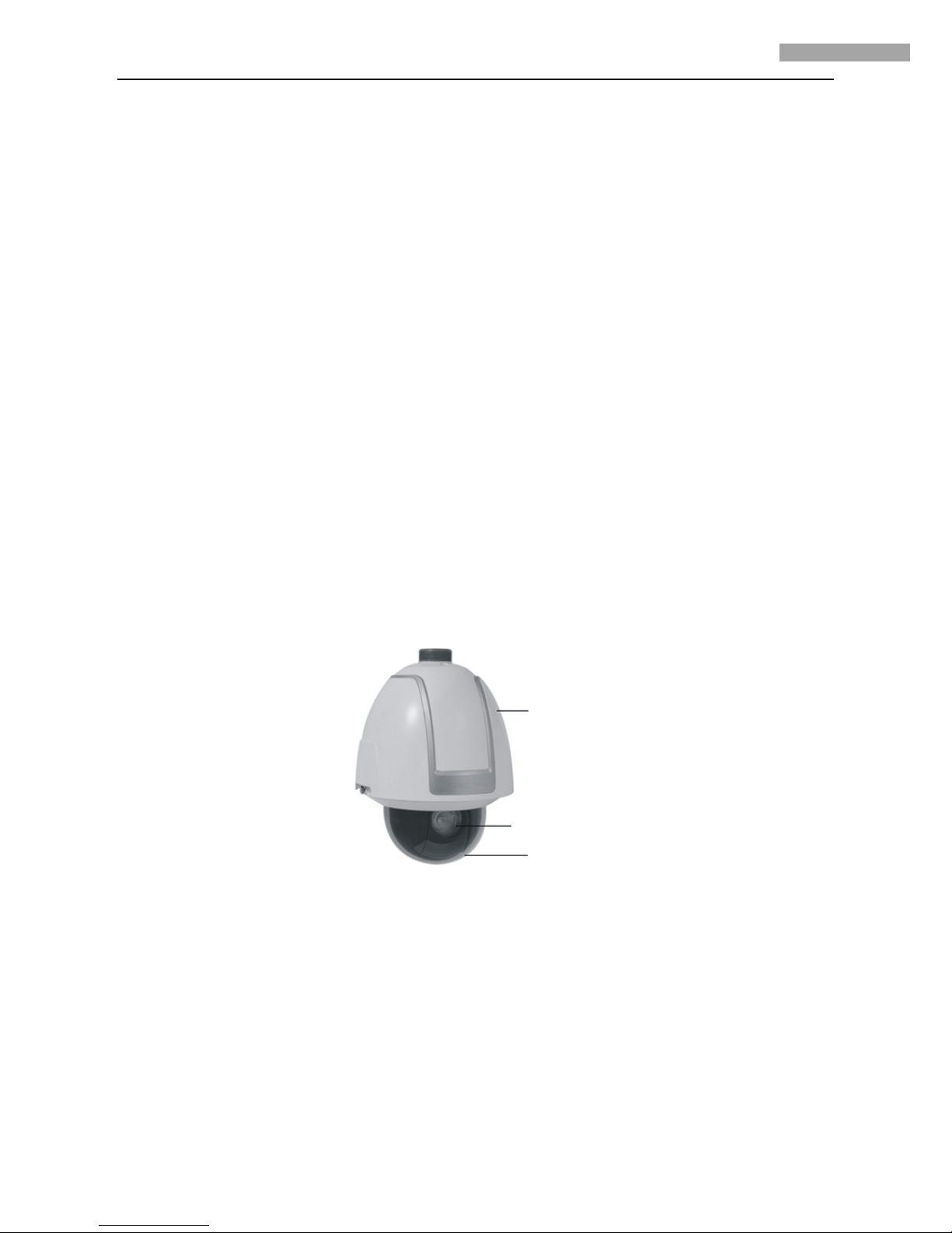
1.2 Outline
Back Box
Back Box
Dome Dr iv e
Bubble
5 Inch Network High Speed Dome
1.3 Functions
Multi-lingual OSD Menu
The dome provides multi-lingual OSD menu for display of system information and setting of dome parameters.
Self-adaptive to Multiple Protocols
The dome is compatible with PELCO-D, PELCO-P, HIK-Code protocol, etc., and is capable of being self-adaptive to these protocols
without need of selecting protocol by DIP switch settings.
Keyboard Control
Page 7

5 Inch Network High Speed Dome User Manual
6
The pan/tilt movement and zoom actions of dome can be controlled by the control keyboard, DVR, matrix, etc.
Limit Stops
The dome can be programmed to move within the limit stops (left/right, up/down) which are configurable by the control keyboard,
DVR or client application software.
Auto Scan
The dome provides 5 scanning modes: pan scanning, tilt scanning, frame scanning, random scanning and panorama scanning. The
scanning speed can be set by OSD menu from level 1 to 40, with the corresponding speed ranging from 1°/second to 40°/second.
Preset Freeze Frame
This feature freezes the scene on the monitor when going to a preset. This allows for smooth transition from one preset scene to
another and also guarantees that masked area will not be revealed when going to a preset.
Presets
Each of the user-definable presets can be programmed to use pan, tilt, camera settings and other settings. When preset is called, the
dome will automatically move to the defined position. User is allowed to add, modify, delete and call each preset.
Label Display
The on-screen label of the preset title, azimuth/elevation, zoom and other operations can be programmed by menu and displayed on the
monitor.
Auto Flip
In manual tracking mode, when a target object goes directly beneath the dome, the dome will automatically rotate 180 degrees in
horizontal direction to maintain continuity of tracking. When the dome rotates (flips), the camera starts moving upward as long as you
continue to hold the joystick in the down position. This function can be realized by image center flip depending on different camera
models. The feature can be enabled/disabled through the menu.
Privacy Mask
The privacy mask allows a user to program user-defined areas that cannot be viewed by the operator of the dome system. A masked
area will move with pan and tilt functions and automatically adjust in size as the lens zooms telephoto and wide.
3D Intelligent Positioning
The speed dome can be controlled with the 2 buttons and scroll of mouse can be used under HIK-Code protocols with devices and
client software. Click on a certain area and the device will move to the scene with corresponding point as the center. When a
rectangular area is selected by left-clicking the mouse, device will move to its center and enlarge it. With right-clicking, the lens will
zoom in, and the scroll can easily make the lens zooming, and mouse operation automatically incorporates zooming effect.
Note: Please refer to Section 4.2.2 3D Intelligent Positioning for the specific instructions.
Proportional Pan/Tilt
Proportional pan/tilt automatically reduces or increases the pan and tilt speeds in proportion to the amount of zoom. At telephoto zoom
settings, the pan and tilt speeds will be slower for a given amount of joystick deflection than at wide zoom settings. This keeps the
image from moving too fast on the monitor when there is a large amount of zoom.
Auto Focus
The
auto focus enables the camera to focus automatically to maintain clear video images.
IR Cut Filter
The IR cut filter can be set to Auto, Day and Night. In auto mode, the camera is capable of automatically switching Black & White
mode (Night) and Color mode (Day) with regard to environment lightening conditions. In manual switch mode, user can increase
sensitivity in low light conditions by switching to Black & White mode, while the Color mode is preferred in normal lighting
conditions.
Low Light Electronic Shutter
The shutter speed will automatically slow down in low illumination conditions to maintain clear video images by extending the
exposure time. The feature can be enabled/disabled by the menu.
Page 8

5 Inch Network High Speed Dome User Manual
7
Backlight Compensation (BLC)
If a bright backlight is present, the subjects in the picture may appear dark or as a silhouette. Backlight compensation (BLC) enhances
objects in the center of the picture. The dome uses the center of the picture to adjust the iris. If there is a bright light source outside of
this area, it will wash out to white. The camera will adjust the iris so that the object in the sensitive area is properly exposed.
Wide Dynamic Range (WDR)
When the Wide Dynamic Range (WDR) function is on, the dome is able to balance the brightest and darkest sections of a scene to
produce a picture that is better balanced in lighting and provides more details.
White Balance (WB)
This feature automatically processes the viewed image to retain color balance over a color temperature range. The default setting for
white balance is AUTO.
Patrol
The high speed dome provides up to 8 patrols. In each patrol, user is allowed to specify the scanning track by a group of user-defined
presets, with the scanning speed between two presets and the dwell time at the preset separately programmable.
Pattern
A pattern is a memorized, repeating series of pan, tilt, zoom, and preset functions that can be recalled with a command from a
controller or automatically by a configured function (alarm, park, time task, or power-up). By default the focus and iris are in auto
status during the pattern is being memorized.
Power Loss Position
The dome supports the power loss position capability with the predefined dwell time. It allows the dome to resume its previous
position after power is restored.
Alarm Response Action
The speed dome supports 2 alarm inputs which can be set to NO (normally open), NC (normally closed) or OFF. Upon having received
the alarm input signal, the dome will automatically activate a user-defined action, which can be programmed to patrol, pattern or preset
callup.
AUX Output
An auxiliary output is a configurable signal from the dome back box that can trigger another device to operate. The dome provides 2
auxiliary outputs: AUX1 and AUX2. The auxiliary output type can be set to NO or NC by menu. And the alarm dwell time is
configurable as well.
User Management
The dome allows the users to be edited in groups with different levels of permission. In the admin login status, the user is allowed to
configure the user groups and user parameters. Multiple users are allowed to access and control the same network speed dome via
network simultaneously.
1.4 Features
Built-in WEB Server
1 channel of compressed video stream transmitted via network and decoded for local display;
Up to 6 domes can be simultaneously connected via network;
Support multiple network transmission protocols;
WEB access for WAN applications;
Management of dome configuration and user permission administration via Ethernet;
IP address dynamic allocation.
Built-in Driver/Receiver
Full-digital design, with power-off protection for all data;
Page 9

5 Inch Network High Speed Dome User Manual
8
Integrated design ensures high reliability;
256 presets and 8 patrols programmable; each patrol with a maximum of 32 presets configurable;
4 patterns, with the recording time reaching up to 10 minutes;
RS-485 bus control;
Up to 24 privacy mask areas programmable (depending on camera models)
Self-adaptive to PELCO-D, PELCO-P, HIK-Code, etc., with various baud rates selectable.
Built-in Pan/Tilt
High-precision motor drive, stable operation, sensitive reaction and precise positioning;
Integrated design with compact construction;
360° continuous rotation;
Low-speed movement ensures high image stability;
Preset positioning tolerance less than 0.1°
Built-in Zoom Lens
High sensibility and high resolution
Auto focus
Auto gain
Auto white balance
Auto IR cut filter
1.5 Default IP, User Name and Password
Default IP: 192.0.0.64
User Name: admin
Password: 12345
Page 10

9
5 Inch Network High Speed Dome User Manual
Chapter 2 Operation Instructions
2.1 Power-up Action
After the power is applied, the speed dome will perform self-test action that begins with lens actions and then pan and tilt movement.
After completion of power-up self-test actions, the interface as shown in Figure 2.1 will be displayed on screen for 40 seconds.
The System Information displayed on the screen includes the Dome Address, Protocol, Version and other information. The
COMMUNICATION refers to the baud rate, data bit and stop bit of the dome, e.g., “2400, 8, 1” indicates the dome is configured with
the baud rate of 2400, 8 data bits and 1 stop bit. Please refer to Section 3.3.1 for detailed information.
MODEL DS-2DF1-517
ADDRESS 0
COMMUNICATION 2400,8,1
SOFTWARE VERSION 2. 0.1
LANGUAGE ENGLISH
Figure 2.1
2.2 Presets with Special Functions
The following presets are predefined with special functions:
Call Preset Function Call Preset Function
33 Auto flip 93 Set manual limit stops
34 Pan zero 94 Remote reboot
35 Patrol 1 95 Access main menu
36 Patrol 2 96 Stop a scan
37 Patrol 3 97 Start random scanning
38 Patrol 4 98 Start frame scanning
39 IR cut filter in 99 Start pan scanning
40 IR cut filter out 100 Start tilt scanning
41 Pattern1 101 Start panorama scanning
42 Pattern2 102 Patrol 5
43 Pattern3 103 Patrol 6
44 Pattern4 104 Patrol 7
92 Enable limit stops setting 105 Patrol 8
Page 11

5 Inch Network High Speed Dome User Manual
10
2.3 Label Display
The dome allows you to configure how labels are displayed on the monitor. The following labels are available:
Zoom: Identifies the amount of magnification.
Direction: Displays compass direction, with the format of NEXXX TXXX. The XXX following NE refers to the degrees in northeast
direction, while the XXX following T indicates the degrees in vertical position. The north direction can be set by menu. E.g., NE235
T035 indicates the current position of the dome is in 235 degrees in northeast and 35 degrees in vertical position.
Alarm Message: Displays activated alarm message.
Time: Support for time display.
Preset Title: Identifies preset being called.
Page 12
5 Inch Network High Speed Dome User Manual
11
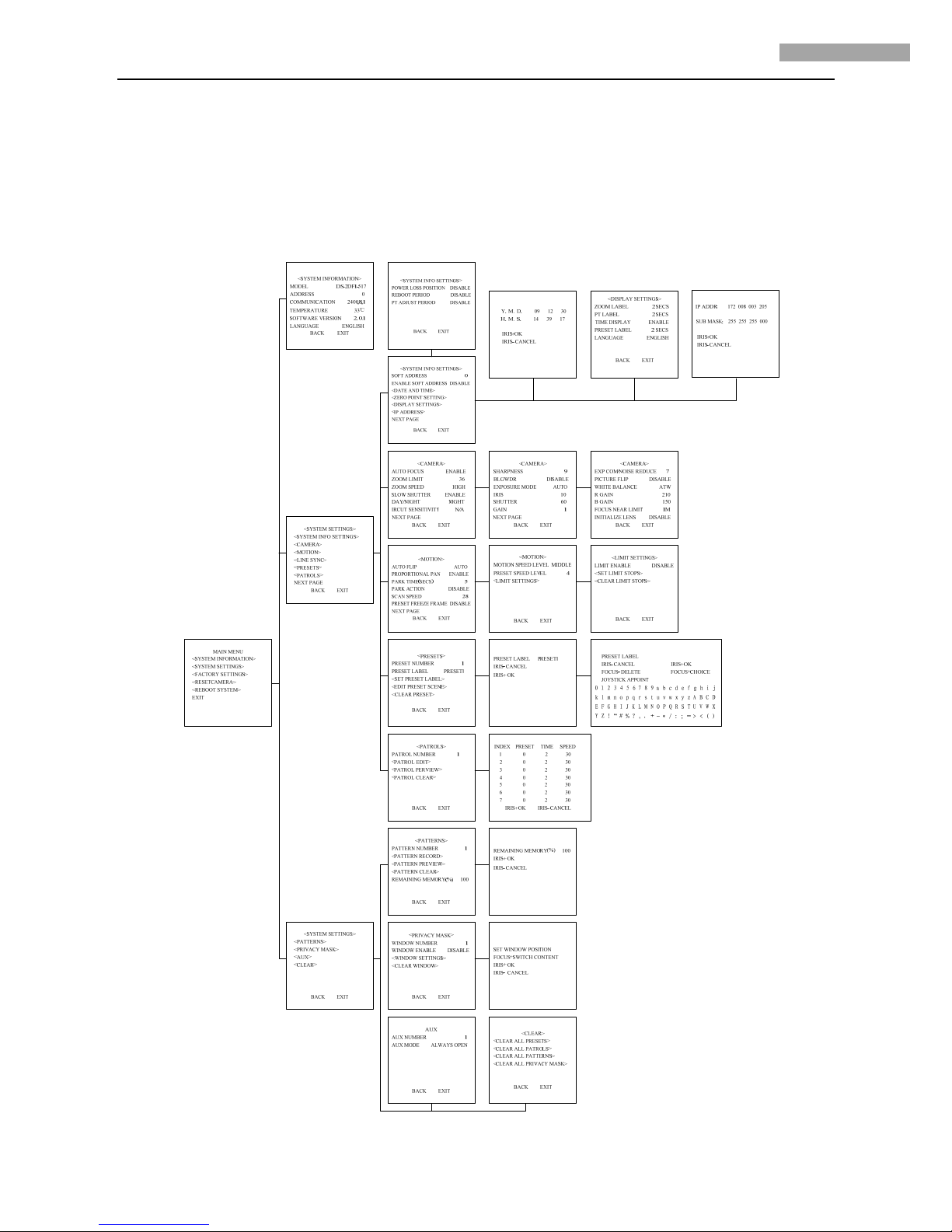
Chapter 3 Menu Operation
Note: The menu varies depending on camera models.
Menu T r ee
Page 13
5 Inch Network High Speed Dome User Manual
12
3.1 MAIN MENU
After logon to IE browser or client software, call preset 95 to access the main menu of the dome. Refer to Figure 3.1.1.
Click the direction buttons on PTZ control section to move the cursor to the selected menu item. Press IRIS+ to confirm, i.e., operation
can be done on this menu options. If current menu contains sub-menu, enter the corresponding sub-menu.
To perform operation on menu option, the selected number behind menu item can be changed by clicking up and down buttons. Click
IRIS+ to confirm and return to previous menu. The same procedure is followed for the next operation for which no description is given.
Select Exit menu option to confirm and exit from menu operation.
MAIN MENU
<SYSTEM INFORMATION>
<SYSTEM SETTINGS>
<FACTORY SETTINGS>
<RESETCAMERA>
<REBOOT SYSTEM>
EXIT
<SYSTEM INFORMATION>
MODEL DS-2DF1-517
ADDRESS 0
COMMUNICATION 2400,8,1
TEMPERATURE 33℃
SOFTWARE VERSION 2. 0.1
LANGUAGE ENGLISH
BACK EXIT
Figure 3.1.1 Figure 3.2.1
3.2 SYSTEM INFORMATION
This menu displays current dome system information, as shown in Figure 3.2.1. Information in menu option cannot be changed and
Temperature refers to internal temperature of dome.
Move the cursor to Back and click IRIS+ to return to the previous menu, or move the cursor to Exit and click IRIS+ to save the settings.
Operation is similar to all other submenus.
3.3 SYSTEM SETTINGS
Enter the SYSTEM SETTINGS menu, as shown in Figure 3.3.1 and Figure 3.3.2.
Note: Enter the next page by moving the cursor beside NEXT PAGE and click IRIS+ button.
<SYSTEM SETTINGS>
<SYSTEM INFO SETTINGS>
<CAMERA>
<MOTION>
<LINE SYNC>
<PRESETS>
<PATROLS>
NEXT PAGE
BACK EXIT
<SYSTEM SETTINGS>
<PATTERNS>
<PRIVACY MASK>
<AUX>
<CLEAR>
BACK EXIT
Figure 3.3.1 Figure 3.3.2
Page 14
5 Inch Network High Speed Dome User Manual
13
3.3.1 SYSTEM INFO SETTINGS
The SYSTEM INFO SETTINGS menu is used for setting the soft address, date and time, display information, etc. Refer to Figure
3.3.3 and Figure 3.3.4.
SOFT ADDRESS
When the ENABLE SOFT ADDRESS option is set to ENABLE, the speed dome will use the soft address, and the addresses from 1 to
255 selectable. Please note the dome address range supported by the current control keyboard. When the ENABLE SOFT ADDRESS
option is set to DISABLE, the address set by DIP switch is used. When the address is set to 0, the dome is capable of receiving the
control command from the control device of any address; when the address of the control device is set to 0, then the speed dome of any
address can be controlled as well. Refer to Figure 3.3.3.
<SYSTEM INFO SETTINGS>
SOFT ADDRESS 0
ENABLE SOFT ADDRESS DISABLE
<DATE AND TIME>
<ZERO POINT SETTING>
<DISPLAY SETTINGS>
<IP ADDRESS>
NEXT PAGE
BACK EXIT
<SYSTEM INFO SETTINGS>
POWER LOSS POSITION DISABLE
REBOOT PERIOD DISABLE
PT ADJUST PERIOD DISABLE
BACK EXIT
Figure 3.3.3 Figure 3.3.4
Y. M. D. 09 12 30
H. M. S. 14 39 17
IRIS+OK
IRIS- CANCEL
Figure 3.3.5
DATE AND TIME
The DATE AND TIME allows user to set the date and time of the dome. As shown in Figure 3.3.5, the message indicates the current
date and time is 15:33:25 on January 18
th
, 2007.
Use the Left and Right buttons to select the option, and click the Up and Down buttons to modify the value.
ZERO POINT SETTING
Enter the ZERO POINT SETTING menu and then use the direction buttons to define the amount of pan from zero degrees vertical and
the amount of tilt from zero degrees horizontal, and finally press the Iris+ button to save settings and exit the current menu.
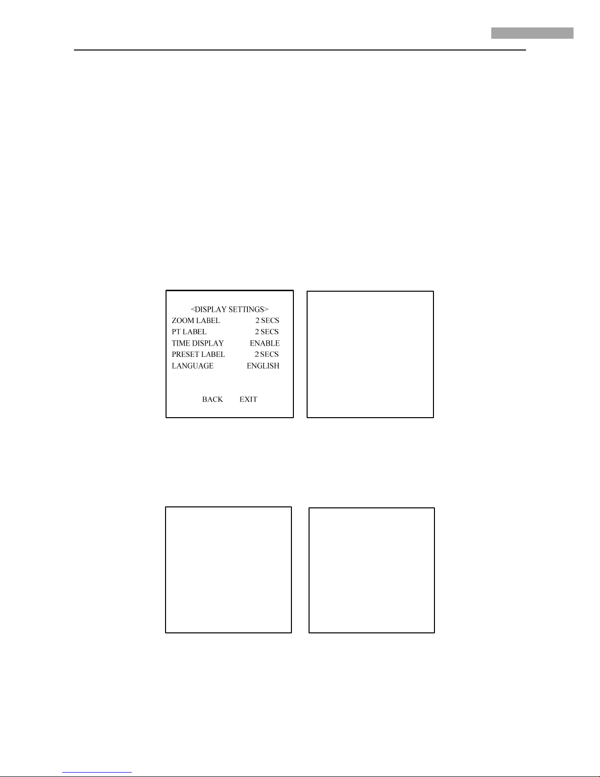
DISPLAY SETTINGS
The DISPLAY SETTINGS menu is displayed in two pages, as shown in Figure 3.3.6.
Each item can be set with the separate display time on screen from 2sec, 5sec and 10sec selectable, or set to be ON or OFF. The preset
display position can overlapped the display positions of azimuth/elevation and zoom. If both of the ZOOM SHOW and the PT SHOW
are set to ON, then in the preset operation status, the preset label will be displayed all the time; while in other operation status, the
Page 15
5 Inch Network High Speed Dome User Manual
14
azimuth/elevation and zoom label are displayed all the time in other status. The external alarm response actions can be activated in
non-menu programming mode while disabled in the menu programming mode.
IP ADDRESS
Enter the IP ADDRESS menu and then use the direction buttons to define of value of IP address and sub mask. Finally click the Iris+
button to save settings and exit the current menu.
POWER LOSS POSITION
The dome supports the power loss position capability with the predefined dwell time. It allows the dome to resume its previous
position after power is restored. The function can be set to 30 sec, 60 sec, 300 sec, 600 sec or Disable.
REBOOT PERIOD
The dome reboots at 00:00:00 of the current day for the first time, and the second reboot action will take place after the predefined
period which can be set to 1~7 days or Disable.
PT ADJUST PERIOD
The dome performs pan and tilt self-test at 00:00:00 of the current day for the first time, and the second pan/tilt self-test action will
take place after the predefined period which can be set to 1~7 days or Disable. If the reboot time and the PT adjust time are overlapped
with each other, the system will perform the scheduled reboot with the priority, and no scheduled PT adjust action will be taken.
IP ADDR: 172 008 003 205
SUB MASK: 255 255 255 000
IRIS+OK
IRIS- CANCEL
Figure 3.3.6 Figure 3.3.7
3.3.2 CAMERA SETTINGS
Note: The menu varies depending on camera models.
Enter the Camera Settings menu, as shown in Figure 3.3.8, Figure 3.3.9 and Figure 3.3.10.
<CAMERA>
AUTO FOCUS ENABLE
ZOOM LIMIT 36
ZOOM SPEED HIGH
SLOW SHUTTER ENABLE
DAY/NIGHT NIGHT
IRCUT SENSITIVITY N/A
NEXT PAGE
BACK EXIT
<CAMERA>
SHARPNESS 9
BLC/WDR DISABLE
EXPOSURE MODE AUTO
IRIS 10
SHUTTER 60
GAIN 1
NEXT PAGE
BACK EXIT
Figure 3.3.8 Figure 3.3.9
Page 16

5 Inch Network High Speed Dome User Manual
15
<CAMERA>
EXP COM/NOISE REDUCE 7
PICTURE FLIP DISABLE
WHITE BALANCE ATW
R GAIN 210
B GAIN 150
FOCUS NEAR LIMIT 1M
INITIALIZE LENS DISABLE
BACK EXIT
Figure 3.3.10
AUTO FOCUS
The camera provides three focus modes for selection: ENABLE, DISABLE and PTZ TRIGGER.
In auto focus mode (ENABLE), the camera will allow the lens to remain in focus when using pan, tilt and zoom (PTZ) functions.
In manual focus mode (DISABLE), the focus can be operated manually.
In half-auto focus mode (PTZ TRIGGER), the camera will remain in a fixed focus position when all PTZ motions are stopped. And
when the PTZ motions are resumed, the camera will focus automatically.
ZOOM LIMIT
Zoom limit allows the user to define a limitation on the amount of telephoto zoom. The settings vary depending on camera models.
Zoom amount=optical zoom× digital zoom. When the ZOOM LIMIT is set to the minimum value, it indicates the digital zoom is
disabled, and the optical zoom is in its maximum value.
ZOOM SPEED
Zoom speed allows the user to define the speed at which the dome will go from full wide zoom to the optical zoom, with three levels
selectable: HIGH, MIDDLE and LOW. The default setting is HIGH.
SLOW SHUTTER
The shutter will automatically slow down to obtain clearer figure through exposure time extension under low lightening. The default
setting is ENABLE.
DAY/NIGHT
The IR cut filter can be set to AUTO, DAY and NIGHT. In auto mode, the camera is capable of automatically switching Black &
White mode (NIGHT) and Color mode (DAY) with regard to environment lightening conditions. In manual switch mode, user can
increase sensitivity in low light conditions by switching to Black & White mode, while the Color mode is preferred in normal lighting
conditions. The default setting is AUTO.
The DAY mode can be set by calling preset 39, and the NIGHT mode set by preset 40.
IRCUT SENSITIVITY
The IR cut sensitivity is the light level at which the IR cut filter switches DAY or NIGHT. Three levels are selectable: HIGH, MID and
LOW. The default setting is MID.
Note: This feature varies depending on camera models.
SHARPNESS
The sharpness function enhances picture detail by increasing the aperture gain of the camera and sharpening the edges in the picture.
Levels from 1 to 16 are selectable, with the default setting of level 9.
BLC/WDR
If a bright backlight is present, the subjects in the picture may appear dark or as a silhouette. Backlight compensation (BLC) enhances
objects in the center of the picture. The dome uses the center of the picture to adjust the iris. If there is a bright light source outside of
this area, it will wash out to white. The camera will adjust the iris so that the object in the sensitive area is properly exposed.
Page 17

5 Inch Network High Speed Dome User Manual
16
When the Wide Dynamic Range (WDR) function is on, the dome is able to balance the brightest and darkest sections of a scene to
produce a picture that is better balanced in lighting and provides more details.
Note: The BLC/WDR feature varies depending on camera model. The default setting is for BLC function.
EXPOSURE MODE
The exposure mode can be set to IRIS PRIORITY, SHUTTER PRIORITY, GAIN/MANUAL or AUTO. When it is set to AUTO, the
auto iris, auto shutter and auto gain functions are all enabled; when it is set to IRIS PRIORITY, the iris function adopts the defined
value while the auto shutter and auto gain remain to be enabled; when it is set to SHUTTER PRIORITY, the shutter function adopts
the defined value while the auto iris and auto gain remain to be enabled; and when it is set to GAIN/MANUAL, the gain value can be
adjusted, or the iris, gain and shutter values are all adjustable. The default setting is AUTO.
Note: The Gain/Manual feature varies depending on camera models.
IRIS
The iris is the lens function that opens and closes the iris in response to changing light conditions, with the numeric values from 0 to 17
selectable.
SHUTTER
The Shutter is the duration of the electronic shutter. User can set the shutter speed to 1, 2, 4, 8, 15, 30, 60, 125, 180, 250, 500, 1000,
2000, 4000 or 10000. The numeric value of X indicates the shutter speed is 1/X second.
GAIN
The Gain indicates the amplification degree of the original image signal, with the numeric values from 0 to 15 selectable.
EXP COMP/NOISE REDUCE
The exposure compensation effect can be adjusted through exposure volume adjustment. The numeric values from 0 to 14 are
selectable, with the default setting of 7.
The noise reduce function can be set to OFF, HIGH, MID and LOW. The default setting is MID.
Note: This feature varies depending on camera models.
IMAGE FLIP
This feature allows the video image to be mirrored horizontally and vertically on the screen.
WHITE BALANCE
This feature automatically processes the viewed image to retain color balance over a color temperature range. The dome provides 5
modes for selection: AUTO, INDOOR, OUTDOOR, SELFDEFINE and ATW. When the SELFDEFINE is selected, set the value of
RED and BLUE.
FOCUS NEAR LIMIT
The focus near limit can be set to 1CM, 30CM, 1M or 3M. The feature allows the camera to perform auto focus out of the focus near
limit.
INITIALIZE LENS
This feature enables the camera to perform daily lens initiation action at 00:00:00 to ensure the normal operation.
3.3.3 MOTION SETTINGS
The MOTION menu is displayed in two pages, as shown in Figure 3.3.11 and Figure 3.3.12.
Page 18

5 Inch Network High Speed Dome User Manual
17
<MOTION>
MOTION SPEED LEVEL MIDDLE
PRESET SPEED LEVEL 4
<LIMIT SETTINGS>
BACK EXIT
Figure 3.3.11 Figure 3.3.12
AUTO FLIP
The dome will rotate 180 degrees when the camera tilts downward and goes just beyond the vertical position. When the dome rotates
(flips), the camera starts moving upward as long as you continue to hold the joystick in the down position. Once you let go of the
joystick after the dome rotates, joystick control returns to normal operation. The auto-flip feature is useful for following a person who
passes directly beneath the dome.
PROPORTIONAL PAN
When the PROPORTIONAL PAN is set to ENABLE, the dome will automatically reduce or increases the pan and tilt speeds in
proportion to the amount of zoom. At telephoto pan and tilt speeds will be slower for a given amount of joystick deflection than at
wide zoom settings. This keeps the image fast on the monitor when there is a large amount of zoom.
When the PROPORTIONAL PAN is set to DISABLE, it will be difficult to trace the object at low pan and tilt speeds or no movement
in large amount of zoom.
Note: This feature is enabled all the time while setting the patterns.
PARK TIME (SECS)
This feature allows the dome to begin a specified operation (scan, preset, or pattern) after a configured period of inactivity.
Park time can be configured from 5 to 720 seconds.
Note:
If no control signal is received for a period of time under the following circumstances, no automatic actions will be performed:
1. In the process of performing dome actions by callup of special presets; 2. In the process of performing external alarm response
actions.
PARK ACTION
This feature will define the activity when the dome parks. The selectable park actions include: presets1-8, patterns 1-4, patrols 1-8,
auto scan, tilt scan, random scan, frame scan, panorama scan, or disable.
SCAN SPEED
Scan speed is the degrees per second of the auto scan, tilt scan, frame scan, random scan and panorama scan. Scan speed is adjustable
from 1 to 40 degrees per second through the camera menu.
FRESET FREEZE FRAME
This feature freezes the scene on the monitor when going to a preset. This allows for smooth transition from one preset scene to
another.
MOTION SPEED LEVEL
The manual dome movement speed can be set to HIGH, MIDDLE or LOW.
PRESET SPEED LEVEL
The speed of preset callup can be set from level 1 to 8. The higher level corresponds to the faster preset callup.
LIMIT SETTINGS
Limit stops are configurable stops that limit the pan and tilt range of the dome. There may be left/right and up/down limit stops
Page 19

5 Inch Network High Speed Dome User Manual
18
configurable to define an area. When the LIMIT ENABLE function is set to DISABLE, the movement of dome will not be limited
despite of defined limit stops. Refer to Figure 3.3.13.
<LIMIT SETTINGS>
LIMIT ENABLE DISABLE
<SET LIMIT STOPS>
<CLEAR LIMIT STOPS>
BACK EXIT
Figure 3.3.13
SET LIMIT STOPS
To set limit stops manually:
1. Enter the SET LIMIT STOPS menu.
2. Follow the directions (SET LEFT LIMIT) displayed on the monitor and use the direction buttons to the desired location of left
limit stop.
3. Press the IRIS + button to finish the setting of left limit stop.
4. Follow the same steps to set the right, up and down limit stops in sequence according to the directions displayed on the
monitor.
The new settings of limit stops will overwrite the existed settings.
CLEAR LIMIT STOPS
The defined limit stops can be cleared by this menu.
3.3.4 LINE SYNC
Note: This feature is not supported currently.
3.3.5 PRESETS
The PRESETS menu is displayed as shown in Figure 3.3.14.
<PRESETS>
PRESET NUMBER 1
PRESET LABEL PRESET1
<SET PRESET LABEL>
<EDIT PRESET SCENE>
<CLEAR PRESET>
BACK EXIT
Figure 3.3.14
PRESET NUMBER
The dome provides 256 presets. The PRESET NUMBER displays the preset under current operation. If the preset has been defined, the
Page 20

5 Inch Network High Speed Dome User Manual
19
corresponding number will appear; while no preset is defined, it will display UNDEFINED. The presets which are predefined for
specific functions will not be displayed and no change is allowable. Please refer to page 9 for presets with specific functions.
SET PRESET LABEL
Select SET PREST LABEL to enter the menu shown in Figure 3.3.15, and then press IRIS+ button to enter the menu for editing the
preset label. Refer to Figure 3.3.16.
Use the following functions buttons on the keyboard or the DVR front panel to edit preset label:
IRIS+: Confirm and save the current settings and return to the previous menu.
IRIS-: Cancel the current operation and return to the previous menu.
FOCUS+: Select and enter the character.
FOCUS-: Delete the character currently entered.
Direction Buttons: Move the cursor to select the numbers/lowercases/capitals/symbols.
PRESET LABEL PRESET1
IRIS- CANCEL
IRIS+ OK
Figure 3.3.15 Figure 3.3.16
EDIT PRESET SCENE
Select EDIT PREST SCENE to enter the menu, use the direction buttons to move PTZ to the desired scene and then press the IRIS+ to
confirm the settings and return to the previous menu, or press IRIS- to cancel settings.
Note: the setting of preset scene will be restricted by the limit stops if defined.
CLEAR PRESET
This feature is used for clearing the current preset.
3.3.6 PATROLS
The PATROLS settings menu is shown in Figure 3.3.17.
PATROLS NUMBER
The dome provides 8 patrols numbering from 1 to 8.
<PATROLS>
PATROL NUMBER 1
<PATROL EDIT>
<PATROL PERVIEW>
<PATROL CLEAR>
BACK EXIT
Figure 3.3.17 Figure 3.3.18
Page 21

5 Inch Network High Speed Dome User Manual
20
PATROL EDIT
The EDIT PATROL settings menu is shown in Figure 3.3.18. A patrol can be configured with 32 presets.
To edit a patrol:
1. Use the Up and Down direction buttons to select the preset to be edited.
2. Use the Left and Right direction buttons to select among PRESET, DWELL TIME and SPEED.
3. After having selected the item to be edited, use the Up and Down direction buttons to set values.
4. Follow the same steps to edit the other presets. Click the Down button to enter the next page.
The preset edited in the patrol can be modified or deleted as well. In default setting, the preset number is initialized as 0, the dwell
time is 2 seconds (0-30 seconds selectable) and the patrol speed is level 30 (level 1-40 selectable).
5. Press IRIS+ to save the current settings or press IRIS- to cancel settings and return to the previous menu.
Note: The patrol speed of the dome is shown as below:
Level Speed(
°/s) Level Speed(°/s) Level Speed(°/s)
1 0.3 2 2 3 4
4 6 5 8 6 10
7 12 8 14 9 16
10 18 11 20 12 25
13 30 14 35 15 40
16 45 17 50 18 55
19 60 20 65 21 70
22 80 23 90 24 100
25 110 26 120 27 130
28 140 29 150 30 160
31 170 32 190 33 210
34 230 35 250 36 270
37 290 38 310 39 330
40 350
PATROL PREVIEW
Enter the PATROL PREVIEW menu to view the current patrol if defined, which enables the dome to scan among the presets as
predefined.
PATROL CLEAR
Enter the PATROL CLEAR menu to clear the current patrol.
3.3.7 PATTERNS
A pattern is a memorized, repeating series of pan, tilt, zoom, and preset functions that can be recalled with a command from a
controller or automatically by a configured function (alarm, park, time task, or power-up).
Refer to Figure 3.3.19 for the PATTERNS settings menu:
<PATTERNS>
PATTERN NUMBER 1
<PATTERN RECORD>
<PATTERN PREVIEW>
<PATTERN CLEAR>
REMAINING MEMORY(%) 100
BACK EXIT
REMAINING MEMORY(%) 100
IRIS+ OK
IRIS- CANCEL
Figure 3.3.19 Figure 3.3.20
Page 22

5 Inch Network High Speed Dome User Manual
21
PATTERN NUMBER
The number of pattern under current operation. The dome provides 4 patterns numbering from 1 to 4.
PATTERN RECORD
Enter the PATTERN RECORD menu, as shown in Figure 3.3.20. Operate camera functions to configure the pattern. The
REMAINING MEMORY indicates the memory available to configure the patterns. When it displays 0, no patterns can be memorized
any more.
Note: These 4 patterns can be operated separately and with no priority level. When configuring and calling the pattern, the limit stops
operation and auto flip will be invalid, while the proportional pan is invalid; and the 3D intelligent positioning operation is not
supported (pan/tilt movement and zoom operation cannot be memorized simultaneously).
PATTERN PREVIEW
Enter the PATTERN PREVIEW menu to view the current pattern which has been defined.
PATTERN CLEAR
Enter the PATTERN CLEAR menu to delete the current pattern.
3.3.8 PRIVACY MASK
The window blanking allows a user to configure the four-sided areas that cannot be viewed by the operator of the dome system. A
blanked area will move with pan and tilt functions and automatically adjust in size as the lens zooms telephoto and wide.
Refer to Figure 3.3.21 for the PRIVACY MASK settings menu.
WINDOW NUMBER
The number of window blank under current operation. The dome provides user-defined 24 window blanks numbering from 1 to 24,
and up to 8 windows can be configured at the same image. Specific number of available window blanks varies depending on camera
model.
WINDOW ENABLE
The WINDOW ENABLE can be set to ENABLE or DISABLE. If no window blanking has been configured, then the WINDOW
ENABLE cannot be set to ENABLE.
<PRIVACY MASK>
WINDOW NUMBER 1
WINDOW ENABLE DISABLE
<WINDOW SETTINGS>
<CLEAR WINDOW>
BACK EXIT
SET WINDOW POSITION
FOCUS+SWITCH CONTENT
IRIS+ OK
IRIS- CANCEL
Figure 3.3.21 Figure 3.3.22
WINDOW SETTINGS
To set a window blanking area:
1. Use the joystick or direction buttons to position the cursor beside WINDOW SETTINGS and then press IRIS+ to enter the
window blank settings menu. Refer to Figure 3.3.22. A purple smear window will appear on the screen (the color of window
varies depending on camera models).
2. Follow the instructions that appear on the screen. Use the joystick or direction buttons to move the window to the desired
location.
3. Press FOCUS+ to start the setting of window blank size. Use the joystick or direction buttons to adjust the size of window
Page 23

5 Inch Network High Speed Dome User Manual
22
blanking area. After completion, press IRIS+ to save settings, and the window color will turn to gray.
Note: The tilt range for configuring the window blank area is from 0~70°and 110~180°.
CLEAR WINDOW
Enter the CLEAR WINDOW menu to delete the current window blank.
3.3.9 AUX
An auxiliary output is a configurable signal from the dome back box that can trigger another device to operate. Refer to Figure 3.3.23
for the AUX settings menu.
AUX NUMBER
Select AUX1 or AUX2 through this item.
AUX MODE
It is used for defining alarm output type. Available settings include ALWAYS OPEN (default) and ALWAYS CLOSE, which
correspond to normally open and normally closed respectively.
Figure 3.3.23
3.3.10 CLEAR
Refer to Figure 3.3.24 for the CLEAR settings menu.
Use this menu to clear all user-defined settings, including presets, patrols, patterns and privacy mask.
<CLEAR>
<CLEAR ALL PRESETS>
<CLEAR ALL PATROLS>
<CLEAR ALL PATTERNS>
<CLEAR ALL PRIVACY MASK>
BACK EXIT
Figure 3.3.24
Page 24

5 Inch Network High Speed Dome User Manual
23
3.4 FACTORY SETTINGS
Use this function to reset all dome settings to factory default parameters, including:
Dome Address 0
Baud Rate 2400bps
120Ω matching resistance Off
Soft Address Off
Azimuth Zero Zero angle
Auto Focus On
Zoom Limit Max Optical Zoom
Zoom Speed High
Low Light Limit Off
IR Cut Filter Auto
Backlight Comp Off
AE Mode Auto
Exposure Comp/Noise Reduce 0
White Balance Auto
Auto Flip Auto
Proportion Pan On
Park Time 5 seconds
Park Action None
Scan speed 28 °/second
Preset Image Freeze Off
Limit Stops Off
Alarm Inputs Off
AUX1/AUX2 NO
AUX1/AUX2 Dwell Time 5 second
Alarm Display/Time Display On
Display of Zoom, Azimuth/Elevation and
Preset Label display
Display for 2 seconds
3.5 RESET CAMERA
This function is used to reset all camera settings to factory default parameters.
3.6 REBOOT SYSTEM
This function is used to reboot the system.
Page 25

5 Inch Network High Speed Dome User Manual
24
Chapter 4 Access to Network Speed Dome
Note: This chapter has described the configuration for the network speed dome through IE or client software.
There are several network parameters of the network speed dome that need to be set after the hardware installation. Those parameters
including IP address, subnet mask and port number, etc. can be set through various kinds of methods, two methods of which are
introduced as below.
1. Set the network speed dome parameters such as IP address and PPPOE through IE.
2. Set the network speed dome parameters through the client software.
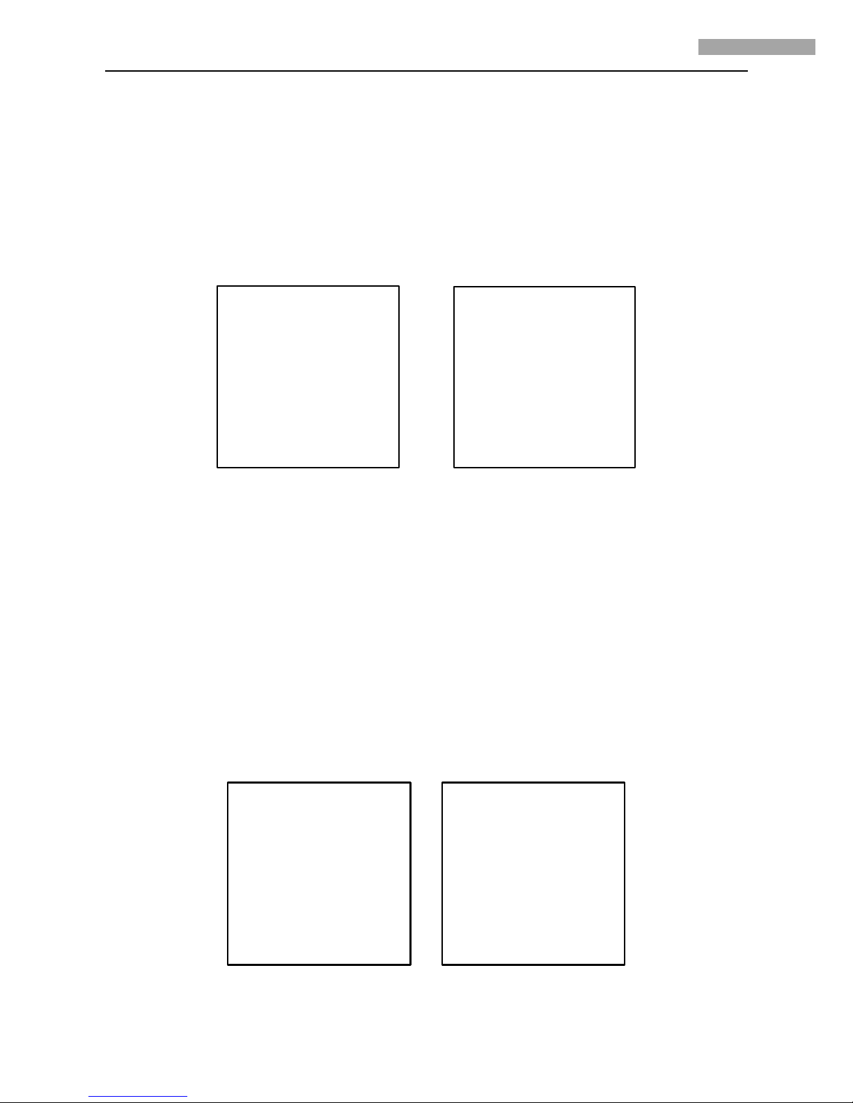
Please make sure that the PC and network speed dome are correctly connected and network connection is established successfully
before the configuration. Two different ways of connection are showed as Figure 4.1 and Figure 4.2.
Figure 4.1 Straight Line Connection Figure 4.2 Crossover Line Connection
4.1Access through IE
When the network connection between the dome and PC has been successfully established, open IE browser and input the IP address
of dome (e.g., 192.0.0.64). The system will remind you to install the ActiveX control. Click and install the ActiveX control.
The system will display the warning message as shown in Figure 4.1.1.
Note: If the ActiveX control installation is blocked by the related software in PC, the following warning message will appear, as show
in Figure 4.1.1. Click Yes to install the ActiveX control.
Page 26

5 Inch Network High Speed Dome User Manual
25
Figure 4.1.1
If it still fails to install the ActiveX Control, please open the IE browser and set the security level to Low in Tools/Internet
Options/Security/Customize or enable the ActiveX Controls and Plug-Ins directly. Refer to Figure 4.1.2. For safety on the Internet,
once you can view the video from camera, the security level can be resumed to “default level”.
Figure 4.1.2 Security Settings
The dome has the default IP as 192.0.0.64, default port as 8000, user name as admin and password as 12345. The administrator can
create up to 15 separate operators with different permission levels. To access the dome through IE, input the IP address in the address
column, and the Login dialog box will pop up as Figure 4.1.3. Input your user name and password, and then click Login to enter the
Page 27

5 Inch Network High Speed Dome User Manual
26
Live Preview interface. Double click the Camera 01 or Preview button to view the menu as Figure 4.1.4. Right double click the
Camera 01 channel, and the Main Stream, Sub Stream and Open Sound options will pop up.
Figure 4.1.3 Login
Figure 4.1.4 Live Preview
Page 28

5 Inch Network High Speed Dome User Manual
27
As shown in Figure 4.1.4, the Playback and Log functions are operable only when the speed dome is configured with SD memory card
(above 1G).
Note: If the speed dome is configured with SD card, the SD card must be formatted before use by clicking Enter Remote
Configuration in Configure menu to enter the HDD management.
Figure 4.1.5 Configuration
To set the dome parameters through IE browser, click Configure to enter the Remote Configuration dialog box, and set the parameters
including IP address, etc., as shown in Figure 4.1.6.
Call preset 95 to access the main menu of speed dome, and use the up/down/left/right buttons to select the submenu and then click
IRIS+ button to enter the submenu to be configured.
Please refer to User Manual of iWMS-4000 (V2.0) for detailed information about Remote Configuration.
Page 29

5 Inch Network High Speed Dome User Manual
28
Figure 4.1.6 Remote Configuration
4.2Access by Client Software
4.2.1 Configuration through Client Software
After the installation of iWMS-4000 (V2.0), click Start->>Program->> iWMS-4000 (V2.0) to start the client software and a dialog box
of Register Administrator will appear, as shown in Figure 4.2.1. Input the user name and password for registration.
Note: The password should be no less than 6 characters.
Figure 4.2.1 Register Administrator
/After the registration is succeed, input the user name and password in the User Login dialog box and then click Login to enter the
Preview interface. Refer to Figure 4.2.3:
Page 30

5 Inch Network High Speed Dome User Manual
29
Figure 4.2.2 User Login
Figure 4.2.3 Preview Interface
Click
from the menu bar to enter the configuration interface. Refer to Figure 4.2.4. Right click the blank on the left and
select Add Area.
Page 31

5 Inch Network High Speed Dome User Manual
30
Figure 4.2.4 Add Area
The Add Area dialog box will pop up, as shown in Figure 4.2.5. Input the area name in the text box and click OK to save the area.
Figure
4.2.5 Add Area Name
The area name added will appear under the site tree. Refer to Figure 4.2.6. Right click the area name and select Add Device.
Page 32

5 Inch Network High Speed Dome User Manual
31
Figure 4.2.6 Add Device
The Add Device dialog box will pop up, as shown in Figure 4.2.7. Input the device name, register mode (Normal IP), device IP (e.g.,
172.8.3.205), user name (admin), password (12345), port (8000) and channel No. (1) in the text boxes and click OK to save the device
information.
Figure 4.2.7 Add Device Information
The device name added will appear under the site tree. Refer to Figure 4.2.8.
Page 33

5 Inch Network High Speed Dome User Manual
32
Figure 4.2.8 Site Tree
After having added the site tree, click the Preview button from the menu bar to enter the Preview interface, as shown in Figure 4.2.9.
Double click the channel name under the site tree to view the camera video.
Figure 4.2.9 Preview Interface
Page 34

5 Inch Network High Speed Dome User Manual
33
In the Preview interface, call preset 95 to access the main menu of speed dome, and use the up/down/left/right buttons to select the
submenu and then click IRIS+ button to enter the submenu to be configured. Refer to Figure 4.2.10.
Figure 4.2.10 Enter Main Menu
Please refer to User Manual of iWMS-4000 (V2.0) for detailed information about configuration.
4.2.2 3D Intelligent Positioning
Select the 3D Position section from the Preview interface, and the icon will replace the mouse icon. Use the left key of mouse to
click on the desired position in the video image and drag a rectangle area in the lower right direction, then the dome system will move
the position to the center and allow the rectangle area to zoom in. Use the left key of mouse to drag a rectangle area in the upper left
direction to move the position to the center and allow the rectangle area to zoom out. Refer to Figure 4.2.12 and Figure 4.2.13. Use the
scroll of the mouse to realize the PTZ operation, and the proportional pan/tilt can be achieved during 3D positioning. In live preview
interface, the dome can be controlled by holding and dragging the left button of mouse. Refer to Figure 4.2.14.
Page 35

5 Inch Network High Speed Dome User Manual
34
Figure 4.2.11 3D Position Icon
Figure 4.2.12 3D Positioning
Figure 4.2.13 3D Positioning
Page 36

5 Inch Network High Speed Dome User Manual
35
Clicking and dragging the mouse from upper left to lower right will realize zoom in function, and from lower right to upper left will
realize zoom out function.
Figure 4.2.14 3D Positioning
4.2.3 Presets
Add Preset: After having moved PTZ to the desired position, click the icon from the Preview interface, select a preset
number from the list, and finally click the Add Preset button to enter the Add Preset dialog box. Input the preset name in the text box,
and then click OK to add the preset. Refer to Figure 4.2.15 and Figure 4.2.16. The preset can also be added by right-clicking the preset
number and select Add submenu.
Figure 4.2.15 Add Preset Figure 4.2.16 Add Preset
Page 37

5 Inch Network High Speed Dome User Manual
36
Figure 4.2.17 Input Preset Name
Call Preset: Select a predefined preset from the list and click the Call preset button to call a preset. Refer to Figure 4.2.18.
Figure 4.2.18 Call Preset
Delete Preset: Select a predefined preset from the list and click the Delete preset button to delete a preset. Refer to Figure 4.2.19. The
system will pop up a message as shown in Figure 4.2. 20. Click OK to delete the preset.
The preset can also be deleted by right-clicking the predefined preset and select Delete submenu.
Figure 4.2.19 Delete Preset Figure 4.2.20 Delete Preset
Modify Preset: Right-click the predefined preset from the list and select Modify submenu to enter the Modify Preset dialog box. Input
the new preset name in the text box, and then click OK to modify the preset. Refer to Figure 4.2.21 and Figure 4.2.22.
Page 38

5 Inch Network High Speed Dome User Manual
37
Figure 4.2.21 Modify Preset Figure 4.2.22 Modify Preset
4.2.4 Patrols
Set Patrol: Click the icon from the Preview interface, click the Patrol Setting button or select Patrol Setting from the
right-click submenu to enter the patrol settings menu. As shown in Figure 4.2.23. In the Patrol Setting menu, user may select a patrol
number to be programmed from the drop-down list, and then add a patrol point, in which the preset number (1~256), dwell time
(1~128 seconds) and dwell speed (1~ 40) can be set. Click Save to finish the settings of the current patrol number. Continue to set
other patrol numbers by following the same steps.
Note: Up to 8 patrols can be added, and each patrol can be configured with a maximum of 32 presets.
Figure 4.2.23 Patrol Setting Figure 4.2.24 Patrol Setting
Call Patrol: Select a predefined patrol from the list and click Call the Patrol button to call a patrol. Refer to Figure 4.2.25.
Stop Patrol: Select a predefined patrol from the list and click Stop the Patr ol button to stop a patrol. Refer to Figure 4.2.26.
Page 39

5 Inch Network High Speed Dome User Manual
38
Figure 4.2.25 Call Patrol Figure 4.2.26 Stop Patrol
4.3 Configuration by DS-9000 Series DVR
Prior to configuration for the network speed dome through DS-9000 series Hybrid DVR, please make sure the speed dome has been
connected to the same network segment with DVR and the network settings for DVR has been properly configured. In DS-9000 DVR,
click Menu->>Setting->>Camera to enter the camera management menu, and then select Add to enter IP Channel Settings menu, as
shown in Figure 4.3.1.
Figure 4.3.1 Camera Management Figure 4.3.2 IP Channel Settings
If the network speed dome and DVR are in the same segment, select the device from the list to be added and then input the user name
and password in the lower dialog box, and finally click OK to add the device. Refer to Figure 4.3.2.
If the network speed dome is offline or not in the same segment with DVR, manually input the parameters of the device, including IP
address, manage port, channel port, user name and password, and finally click OK to add the device. The connection between dome
and DVR will be automatically established when the dome is online or the device is successfully added.
Page 40

5 Inch Network High Speed Dome User Manual
39
Figure 4.3.3 IP Channel Settings
Edit and view the connection status. Refer to Figure 4.3.3. If the Status displays Connect, it indicates the device has been successfully
added.
4.4 Search and Modify IP by SADP
SADP (Search Active Devices Protocol) is a kind of software which can automatically search network speed dome in LAN. User can
modify the IP address, subnet mask and port of the device without visiting IP address of the device. Additionally, password of the
super user in this device can be recovered as default.
SADP software needs to support SADP, so we should install WinPcap at first, which is placed at the directory of SADP software.
4.4.1 Search active devices online
After installing WinPcap, double click sadpdlg.exe. The software will start to search active devices in LAN, and device type, IP
address, Port number, Device Serial No., subnet mask, MAC address, the number of channels, main control and encoding version and
device initiating time are showed in the list, as following:
Page 41

5 Inch Network High Speed Dome User Manual
40
Figure 4.4.1 Search Online Devices
4.4.2 Modify device information
Select the device that needs modification in the device list, then basic information of the device will be demonstrated in the
information column on the right. Click ‘modify’ button to activate IP address, subnet mask, device port editing and password
validating box, as following:
Figure 4.4.2 Modify Device Information
Page 42

5 Inch Network High Speed Dome User Manual
41
Input new IP address, subnet mask, and port number, and click ‘save’ button. If a dialog pops up, showing ‘saved successfully’, that
means you have modified the configuration information; if ‘saving failed’ turns up, click the ‘cancel’ button to quit it.
4.4.3 Resume default password
You can reset the password of the super user as 12345 in case of having forgotten administrator’s password.
Input certain validate code into Resume default password text box, and click OK to finish the administrator’s password initialization.
4.5 Access by WAN
Note: The following settings are for TP-LINK router, which is maybe different from other router’s settings.
Step1: Firstly, select the router’s WAN connection type. As shown in Figure 4.5.1:
Figure 4.5.1 Select WAN Connection Type
Step2: Set the network parameters of the router as shown in Figure 4.5.2. The settings include IP address and subnet mask.
Figure 4.5.2 Set Network Parameters
Step 3: Set the port map in the virtual severs of Forwarding. For example, one speed dome’s ports are 80 and 8000 and its IP address is
192.168.1.23. Another speed dome’s ports are 81 and 8001 and IP is 192.168.1.24. Then, enable all or TCP protocols. Enable the port
map after pressing Save.
Page 43

5 Inch Network High Speed Dome User Manual
42
As the settings mentioned above, map the router’s port 80 and 8000 to the network speed dome at 192.168.1.23; and port 81 and 8001
to the network speed dome at 192.168.1.24. In this way, user can access the 192.168.1.23 through accessing the router’s port 80 and
8000.
Note: The port of the network speed dome cannot conflict with other ports.
Page 44

5 Inch Network High Speed Dome User Manual
43
Appendix 1 Network Cable Connection
Materials and Tools Required
Use an 8-pin twisted pair (within the effective transmission distance of 100m), two standard RJ45 plugs and a RJ45 special tool to
process the network cable.
Note: A network cable tester is recommended to prepare for testing the produced network cable.
Pin Definitions
(1) Pin definitions of the straight network cable used for connecting dome and HUB, switch or other network devices:
Straight Network Cable
(2) Pin definitions of the crossover network cable used for directly connecting dome and PC:
Crossover Network Cable
Page 45

5 Inch Network High Speed Dome User Manual
44
Appendix 2 Lightning & Surge Protection
This product adopts TVS plate lightning protection technology to avoid damage caused by pulse signal that is below 3000W, like
instantaneous lighting, surging, etc. According to the actual situation outdoors, necessary protection measures must be taken to secure
the electrical safety.
1. The distance between signal transmission line and High-voltage equipment or high-voltage cable is at least 50m.
2. Outdoor wiring should better be along the eaves as much as possible.
3. In the open field,
wiring should be buried underground in sealed steel pipe, and the steel-pipe should be one-point
grounding. Overhead routing method is forbidden.
4. In strong thunderstorm area or high induction voltage areas (such as high-voltage transformer substation), high power lightning
protection apparatus and lightning conductor are necessary to be appended.
5. The design for installation and wiring with lightning protection and grounding in mind should be combined with the lightning
protection consideration of the building, and conform to the related national standards and industry standards.
6. The system should be equipotentially grounded, and the grounding equipment must satisfy double-request of system anti-jamming
and electric safety, and it must not appear short circuit and open circuit with the zero conductor of strong grid. When the system is
grounding individual, the resistance should be no more than 4Ω, the section al area of the grounding cable should be no less than
25mm
2
. For grounding instructions, please refer to the Installation Manual of Speed Dome.
Page 46

5 Inch Network High Speed Dome User Manual
45
Appendix 3 RS485 Bus Connection
1. General Property of RS485 Bus
According to RS485 industry bus standard, RS485 is a half-duplex communication bus which has 120Ω characteristic impendence, the
maximum load ability is 32 payloads (including controller device and controlled device).
2. RS485 Bus Transmission Distance
When using 0.56mm (24AWG) twisted-pair line, according to different baud rate, the max transmission distance theory table is shown
as below:
Baud Rate Max Distance
2400BPS 1800m
4800BPS 1200m
9600BPS 800m
The transmission distance will be decreased if we use the thinner cable, or use this product under the strong electromagnetic
interference situation, or there are lots of devices are added to the bus; on the contrary, the transmission distance will be increased.
3. Connection Method and Terminal Resistance
1) RS485 industry bus standard require daisy-chain connection method between any devices, both sides have to connect a 120Ω
terminal resistance (show as Diagram 1), the simplified connection method is shown as diagram 2, but the distance of “D”
should not be too long.
Diagram 1
Diagram 2
2) Connection of 120Ω terminal resistor
The 120Ω terminal resistor can be connected through the DIP switch on the communications board, as shown in Figure3. For a new
dome, the 120Ω matching resistor is defaulted as unconnected, switch on the eighth bit of SW2, it will be connected. Conversely,
switch off the eighth bit of SW2, it will be unconnected.
Page 47

5 Inch Network High Speed Dome User Manual
46
Figure 3
4. Problems in the Practical Application
Normally, users adopt star-shape connection method in construction, under this situation, the terminal resistors must be connected
between two farthest devices (as Figure 4, 1# and 15#), but this connection method is not satisfy the requirement of the RS485
industry standard so that it will lead to some problems such as signal reflection, anti-jamming ability decline when the devices are
faraway. At this time, the dome will be uncontrollable, or self-running, etc.
Figure 4
For such case, the best way is adding a RS485 distributor. This product can effectively change the star-shape connection to which
satisfies the requirement of RS485 industry standard, in order to avoid those problems and improve the communication reliability.
Show as figure 5.
Page 48

5 Inch Network High Speed Dome User Manual
47
Figure 5
4. FAQ of RS485 Bus
Page 49

5 Inch Network High Speed Dome User Manual
48
Appendix 4 24VAC Wire Gauge & Transmission Distance
The following table has described the recommended max. distance adopted for the certain wire gauge when the 24VAC voltage loss
rate is less than 10%. For the AC driven device, the maximum voltage loss rate allowable is 10%. For example, for a device with the
rating power of 80VA which is installed at a distance of 35 feet (10m) away from the transformer, then the minimum wire gauge
required is 0.8000mm.
Wire Gauge
mm
Distance
feet(m)
Power (va)
Page 50

5 Inch Network High Speed Dome User Manual
49
Appendix 5 Table of Wire Gauge Standards
Page 51

5 Inch Network High Speed Dome User Manual
50
 Loading...