

Page 1

TURBO HD
1080P Dome Camera
User Manual
Regulatory Information
FCC Information
FCC compliance: This equipment has been
tested and found to comply with the limits for a
dig ital de vice, p ursuan t to part 1 5 of the FC C
Rul es. The se limi ts are de signe d to provi de
reasonable protection against harmful
interference when the equipment is operated in
a commercial environment. This equipment
gen erates , uses, a nd can rad iate rad io
frequency energy and, if not installed and used
in accordance with the instruction manual, may
cau se harm ful inte rferen ce to rad io
communications. Operation of this equipment in
a residential area is likely to cause harmful
interference in which case the user will be
req uired to c orrec t the inte rferen ce at his o wn
expense.
FCC Conditions
This device complies with part 15 of the FCC
Rules. Operation is subject to the following two
conditions:
1. Th is devi ce may not c ause ha rmful
interference.
2. Th is devi ce must a ccept an y inter ferenc e
received, including interference that may
cause undesired operation.
EU Conformity Statement
upon the purchase of equivalent new equipment,
or dispose of it at designated collection points.
For more information see:
www.recyclethis.info.
2006/66/EC (battery directive):
This product contains a battery that
cannot be disposed of as unsorted
municipal waste in the European
Union.
See the product documentation for specific
batt ery inf ormati on. Th e batter y is marke d with
thi s symbo l, whic h may incl ude let tering t o
ind icate ca dmium ( Cd), le ad (Pb) , or merc ury (Hg ).
UD.6L0201D1548A01
2012/19/EU (WEEE directive):
Products marked with this symbol
cannot be disposed of as unsorted
municipal waste in the European
Union. For proper recycling, return
this product to your local supplier
This product and - if applicable - the
supplied accessories too are marked
wit h "CE" an d compl y theref ore with
the applicable harmonized European
stan dards l isted u nder the L ow Volta ge Direc tive
2006/95/EC, the EMC Directive 2004/108/EC,
the RoHS Directive 2011/65/EU.
1.2 Overview
1.2 .1 Over view of Ty pe I Dome C amera
1.2 .2 Over view of Ty pe Dome C amera
II
1 Introduction
1.1 Product Features
This camera adopts new generation sensor with
high sensitivity and advanced circuit board design
technology. It possesses the features of high
resolution, low distortion, and low noise, etc. It is
extremely suitable for supervisory system and
image processing system.
The main features are as follows:
l
High performance CMOS sensor and high
resolution bring high-quality image;
l
Low illumination;
l
Support IR cut filter with auto switch;
l
OSD m enu, pa ramete rs are con figur able;
l
Support auto white balance, auto gain control,
electronic shutter control and internal
synchronization;
l
SMART IR mode;
l
Unit transmission control;
l
Advanced 3-axis design meets different
installation requirements.
l Ple ase make s ure tha t the dev ice in th e packag e
is in good condition and all the assembly parts
are i nclud ed.
l Make s ure tha t all the re lated e quipm ent is
power-off during the installation.
l Che ck the sp ecifi catio n of the pro ducts f or the
installation environment.
l Check whether the power supply is matched
wit h your po wer outp ut to avo id dama ge.
l Ple ase make s ure the w all is str ong eno ugh to
withstand three times the weight of the camera
and the mounting.
l If th e wall is t he ceme nt wall, y ou need t o inser t
exp ansio n screws b efore yo u instal l the cam era.
If the wall is the wooden wall, you can use
sel f-tap ping sc rew to sec ure the c amera.
l If the product does not function properly,
please contact your dealer or the nearest
ser vice ce nter. Do not d isass emble t he came ra
for repair or maintenance by yourself.
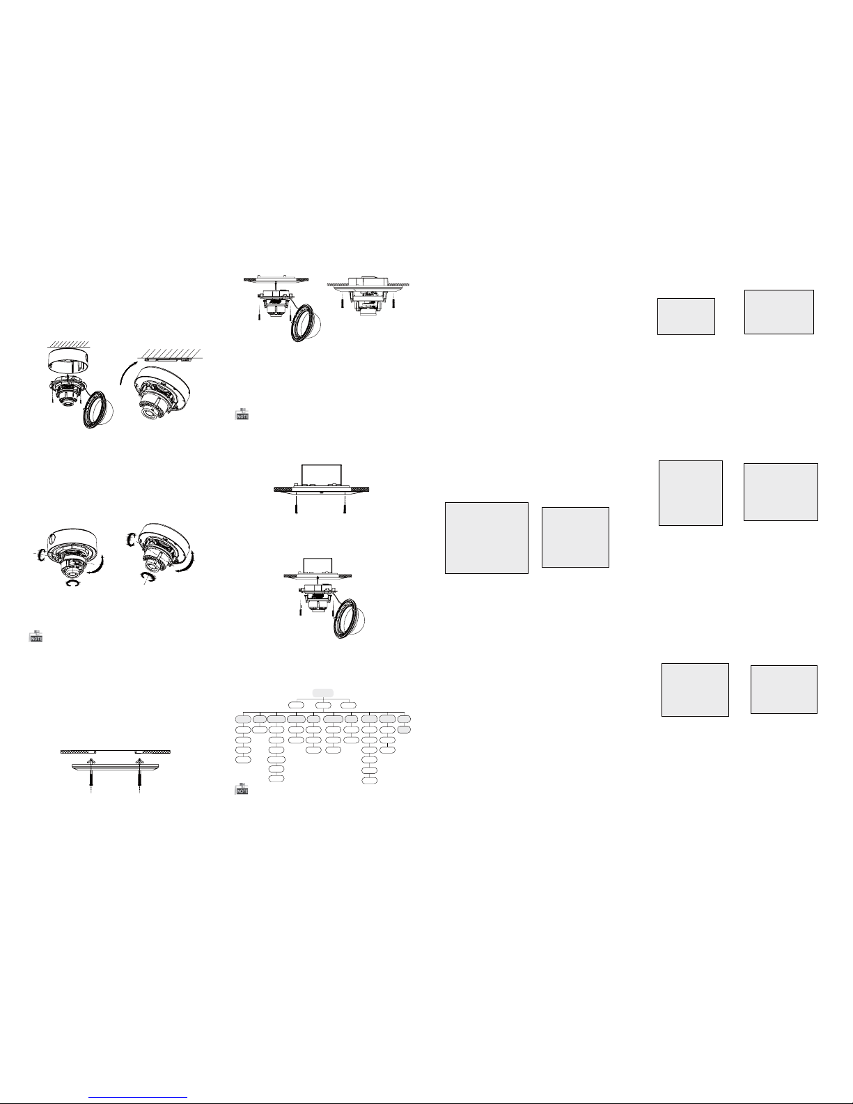
2.1 Ceiling Mounting
Steps:
1.Dr ill the s crew ho les and t he cable h ole on th e
ceiling according to the supplied drill template.
Figure 2-1 The Drill Template
2 Loosen the screws on the bubble of type 1
.
cam era /rot ate the bu bble of t ype2 ca mera to
rem ove the bu bble an d the bla ck line r.
Figure 2-2 Remove the Bubble
For p roper re cycli ng, retu rn the ba ttery t o your
supplier or to a designated collection point. For
more information see: www.recyclethis.info.
2 Installation
Before you start:
Thank you for purchasing our product. If there
are a ny quest ions, o r reque sts, ple ase do no t
hes itate to c ontact t he deal er.
This manual applies to DS-2CE56D5T-(A)VFIR and
DS-2CE56D5T-(A)VPIR3.
Thi s manua l may cont ain sev eral tec hnica l
incorrect places or printing errors, and the
content is subject to change without notice.
The u pdate s will be ad ded to th e new ver sion of
this manual. We will readily improve or update
the products or procedures described in the
manual.
DISCLAIMER STATEMENT
Underwriters Laboratories Inc. (”UL” has not)
tested the performance or reliability of the
security or signaling aspects of this product.
UL ha s only te sted for f ire, sho ck or cas ualty
haz ards as ou tline d in Ul’s St andard (s) for S afety,
UL6 0950- 1. UL Cer tific ation d oes not co ver the
performance or reliability of the security or
sig nalin g aspec ts of thi s produ ct. UL MA KES NO
REPRESENTATIONS, WARRANTIES OR
CERTIFICATIONS WHATSOEVER REGARDING
0100001040603
THE PERFORMANCE OR RELIABILITY OF ANY
SECURITY OR SIGNALING RELATED FUNCTIONS
OF THIS PRODUCT.
Fig ure 1-1 O vervi ew of Type I Do me Came ra
Fig ure 1-2 O vervi ew of Type Dom e CameraII
Type I:
Type I :I
Type I :I
Type I:
Auxiliary Video Output
Black Liner
Bubble
Power C able
HD Vid eo Cabl e
CVBS Cable
Lens
Base plate
CVBS Cable
Back Box
Lens
Bubble
Black Liner
Powe r Cable
HD Video Cable
Auxiliary Video Output
Dip Switch
Dip Switch
Page 2
3 Menu Operation
Figure 3-1 Main Menu
Menu
SCENE
LENS
RESET
EXPOSURE
WB
DAY&NIGHT
BACKLIGHT
NR
SPECIAL
ADJUST
INDOOR
OUTDOOR
INDOOR1
LOWLIGHT
MANUAL
SHUTTER
AGC
SENS-UP
BRIGHTNESS
D-WDR
DEFOG
BLC
HSBLC
ATW
AWC-SET
MANUAL
COLOR
B/W
EXT
2DNR
3DNR
CAM
TITLE
D-EFFECT
MOTION
PRIVACY
LAUGUAGE
DEFECT
VERSION
SHARPNESS
MONITOR
LSC
VIDEO.
OUT
EXIT
SETUP
3.1 VIDEO.OUT
PAL or NTSC is selectable .
3.2 LANGUAGE
Eng lish, J apane se, CHN 1, CHN2 , Korean , Germa n,
French, Italian, Spanish, Polish, etc., are selectable.
3.3SETUP
3.3.1 SCENE
You can select indoor, outdoor, indoor 1 and low
-li ght as th e worki ng envir onmen ts.
3.3.2 LENS
The c amera is e quipp ed with a f ixed le ns.
3.3.3 EXPOSURE
EXPOSURE
1. SHUTTER AUTO
2. AGC OFF
3. SENS-UP ---
4. BRIGHTNESS ---|------ 40
5. DEFOG OFF
6. D-WDR OFF
7. RETURN RET
Figure 3-2 Exposure
SHUTTER: AUTO ,1/25 , 1/50, F LK, 1/2 00, 1/4 00,
1/1 k, 1/2k , 1/5k, 1 /10k, 1 /50k, x 2, x4, x6 , x8, x10 ,
and x15 are selectable.
: You can s et the AG C value fr om 0 to 15.AGC
: You can s et the SE NS-UP t o OFF or AUT O.SENS-UP
: You can s et the br ightn ess valu eBRIGHTNESS
fro m 1 to 100.
: You can s et the de fog func tion as O N toDEFOG
enable the function. Position, size, and the defog
gradation are configurable.
You can s et the D- WDR as ON o r OFF.D-WDR:
3.3.4 Backlight
Backlight Compensation (BLC):
Set t he gain of B LC as Hig h, Midd le, or Lo w.-GAIN:
Press the up/down/left/right button to-AREA:
define the BLC position and size. Select RET or
AGA IN to go bac k the BLC m enu or re -defi ne the
BLC a rea.
Rest ore the B LC setti ngs to th e defaul t.-Default:
HSBLC: Select an HSBLC area. Set the DISPLAY
status as ON. Press the up/down/left/right button
to de fine th e area pos ition a nd size . Set the H SBLC
LEVEL from 0 to 100. Select ALL DAY or Night for the
HSB LC mode . Set the B LACK MAS K statu s as ON or
OFF.
HSBLC
1. SELECT AREA1
2. DISPLAY ON 8
3. LEVEL ---|------40
4. MODE ALL DAY
5. BLACK MASK ON
6. DEFAULT 8
7. RETURN RET
Fig ure 3-3 H SBLC
3.3.5 White Balance (WB)
MANUAL, ATW (Auto-tracking White Balance),
AWC→SET are selectable.
3.3 .6 Day & Ni ght
Color, B/W, and EXT are selectable for DAY and
NIGHT switches.
3.3.7 NR
: You can s et 2D NR sta tus as ON o r OFF.2D NR
: Set the Smart NR status as ON and adjust3D NR
the 3 D smart N R sensi tivit y ranges f rom 0 to 10 0.
Set t he 3D NR LE VEL rang es from 0 t o 100. Set t he
2D&3D NR
1. 2DNR OFF
2. 3DNR ON
8
3. RETURN RET
3D NR
1. SMART NR ON
8
2. LEVEL ------ |--8 0
3. START. AGC - |--------10
4. END. AGC -|--------10
5. RETURN RET
Fig ure 3-4 N R
Fig ure 3-5 3 D NR
3.3.8 SPECIAL
Edi t the came ra titl e on this s ectio n.Camera Title:
D-effect:
Set t he freez e funct ion as ON o r OFF.-FREEZE:
OFF, MI RROR, V -FLIP, and R OTATE ar e-MIRROR:
selectable for mirror.
Define the zoom area by configuring-D-ZOOM:
the p ositi on from PAN & T ILT.
The D-Zoom area, sensitivity-SMART D-ZOOM:
and time are configurable.
Set t he NEG IM AGE as ON or O FF.-NEG.IMAGE:
SPECIAL
1. CAM TITLE ON
8
2. D-DFFECT 8
3. MOTION OFF
4. PRIVACY OFF
5. LANGUAGE ENG
8
6. DEFECT 8
7. RETURN RET
Figure 3-6 Special
MOTION
1. SELECT AREA 1
2. DISPLAY ON8
3. SENSITIVITY ----|----30
4. MOTION VIEW ON
5. DEFAULT 8
6. RETURN RET
Fig ure 3-7 M otion D etecti on
Motion: Select a MOTION area. Set the DISPLAY
status as ON or OFF. Press the up/down/left/right
but ton to def ine the p ositi on and si ze of the a rea.
Set t he SENS ITIVI TY from 0 to 6 0. Set th e MOTIO N
VIE W status a s ON or OFF.
Privacy: Select a PRIVACY area. Set the DISPLAY
stat us as INV, MO SAIC, C OLOR or O FF. Pr ess the
up/down/left/right button to define the position
and s ize of the a rea.
Defect: LIVE D PC, STATIC D PC and Bl ack DPC a re
adjustable in this section.
PRIVACY
1. SELECT AREA 1
2. DISPLAY MOS AIC
8
3. COLOR 10
4. TRANS. 1
5. DEFAULT
8
6. RETURN RET
ADJUST
1. SHARPNESS --------|15
2. MONITOR LCD8
3. LSC OFF
4. RETURN RET
3.3.9 ADJUST
: Adjust the sharpness from 0 to 15.Sharpness
: Monitor CRT, and Monitor LCD areMonitor
selectable.
: Set t he LSC sta tus as ON o r OFF.LSC
3.3.10 RESET
Res et all the s ettin gs to the d efault .
3.3.11 EXIT
Pre ss OK to exi t the men u.
START. AGC l evel as t he thre shold t o enabl e AGC,
and s et the EN D. AGC lev el as the t hresho ld to
disable AGC.
Figure 3-8 Privacy Mask
Figure 3-9 Adjust
Steps:
1.Dr ill the s crew ho les and t he cable h ole in th e
ceiling according to the supplied drill template.
2.Screw the bolts through the mount by aligning
wit h the 2 bol t holes . Fit the t oggle s onto the b olts.
3.P ush the t wo togg le bolt s throug h the two s crew
holes on the ceiling. Rotate the bolt till the toggle
holds the ceiling tightly.
2.2 In-ceiling Mounting
Fig ure 2-5 I nstall t he Moun t
Fig ure 2-6 F ix the Ca mera to th e Mount
Fig ure 2-8 F ix the Ca mera to th e Gang Box
6. Repeat steps 6-8 of the Ceiling Mounting section
to complete the installation.
4.Route and connect the corresponding cables.
5.Fix the camera to the in-ceiling mount with the
supplied screws.
3.Att ach the b ack box of t ype 1 cam era /ba se plate
of type2 camera to the ceiling and secure them
with supplied self-tapping screws.
4.Ro ute the c ables t hroug h the cab le hole .
5.Al ign the c amera wi th the ba ck box/ base pl ate,
and t ighte n the set sc rews to s ecure th e camer a
with the back box/base plate.
Figure 2-3 Fix the Camera to the Ceiling
6. Connect the corresponding cables.
7. Ad just th e camera a ccord ing to the f igure b elow
to get a n optim um angl e.
8. Fi t the bla ck line r on the ca mera and t ighte n the
screws on the bubble of type 1 camera or rotate the
bubble of type 2 camera to complete.
Fig ure 2-4 Zo om and Fo cus Adj ustme nt
You need to purchase an in-ceiling mount separately
if you adopt in-celling mounting.
2.3 In-ceiling Mounting with
Gang Box
Only the type 1 camera supports in-ceiling
mounting with gang box.
1.Repeat steps 2-3 of the In-ceiling Mounting
section to secure the in-ceiling mount (supplied)
to the gang box.
Fig ure 2-7 I nstall t he Moun t
2.Route and connect the corresponding cables.
3.A lign th e camera w ith the g ang box , and tig hten
the s crews to s ecure t he came ra with th e gang box ..
4. Repeat steps 6-8 of the Ceiling Mounting section
to complete the installation.
Type I:
Type I :IType I :IType I :I
0~90°°
0 ~355°°
0 ~355°°
P Direction
R Direction
T Direction
Type I:
0°~355°
0~90°°
0 ~340°°
T Direction
R Direction
P Direction
Type I :I
Type I:
Type I :I
You can c all the m enu and a djust t he came ra
parameters with a coaxial camera controller
(pu rchas e separa tely) . You ca n also ca ll the me nu
with supported TVI DVR.
 Loading...