

Page 1
TURBO HD
TVI Dome Camera
User Manual
UD.6L0201D1931A01
Thank you for purchasing our product. If there
are a ny questions, or requests, please do not
hesitate to contac t th e de al er.
This manual applies to
Type
Type
I
Type
II
This manual may c ontain severa l techni cal
incorrect places or printing errors, and the
content is subject to change without notice.
The updates w il l be a dded to th e ne w ve rsion of
this manual. We will readily improve or update
the products or procedures described in the
manual.
Privacy Notice
Surveillance laws vary by jurisdiction. Check
all relevant laws in your jurisdiction before using
this product for surveillance purposes to ensure
that your use of this product conforms.
Please refer to the product specification for
camera parameters and functions.
0100001050409
Model
DS-2CE56D1T-IRMM
DS-2C E56D1T-VPIR
Regulatory Information
FCC Information
FCC compliance: This equipment has been
tes ted and found to co mp ly w it h th e li mits for a
digital d ev ic e, p ursu ant to part 15 of the F CC
Rules. These limits are designed to pro vi de
reasonable protection against harmful
interference when the equipment is operated in
a commercial environment. This equipment
gen erates, uses, and can rad ia te radio
frequency energy and, if not installed and used
in accordance with the instruction manual, may
cau se harmf ul int er feren ce t o radio
communications. Operation of this equipment in
a residential area is likely to cause harmful
interference in which case the user will be
req ui re d to correct the inte rference at h is o wn
expense.
FCC Conditions
This device complies with part 15 of the FCC
Rules. Operation is subject to the following two
conditions:
1. This device may no t ca us e ha rm fu l
interference.
2. This device must accept any interference
received, including interference that may
cause undesired operation.
EU Conformity Statement
This prod uc t and - if applicable - the
supplied accessories too are marked
with "CE" and com ply therefore w it h
stand ards listed u nder the Low Voltage Directive
2006/95/EC, the EMC Directive 2004/108/EC,
the RoHS Directive 2011/65/EU.
upon the purchase of equivalent new equipment,
or dispose of it at designated collection points.
For more information see:
See the product documentation for specific
bat tery informat io n. The bat tery is ma rke d with
this sy mb ol , wh ic h may in cl ud e le ttering to
indicate cadmium (C d) , le ad ( Pb ), o r me rc ur y (H g) .
For p roper recycling, return the battery to your
supplier or to a designated collection point. For
more information see: www.recyclethis.info.
the applicable harmonized European
2012/19/EU (WEEE directive):
Products marked with this symbol
cannot be disposed of as unsorted
municipal waste in the European
Union. For proper recycling, return
this product to your local supplier
www.recyclethis.info.
2006/66/EC (battery directive):This
product contains a battery that cannot
be disposed of as unsorted municipal
waste in the European Union.
1 Introduction
1.1 Product Features
This series of camera a do pt s ne w gene ration
sensor with high sensitivity and advanced circuit
design technology It features high resolution,.
low image d istort io n an d lo w no is e, e tc , wh ich.
makes it suitable for surveillance system and
image processing system.
l High performance CMOS sensor and high
resolution bring high-quality image;
l Low illumination;
l OSD menu, parameters are configurable;
l Support auto white balance, auto gain control,
l
Support image effect adjustment;
l
Unit transmission control;
l Advanced 3-axis design meets different
installation requirements.
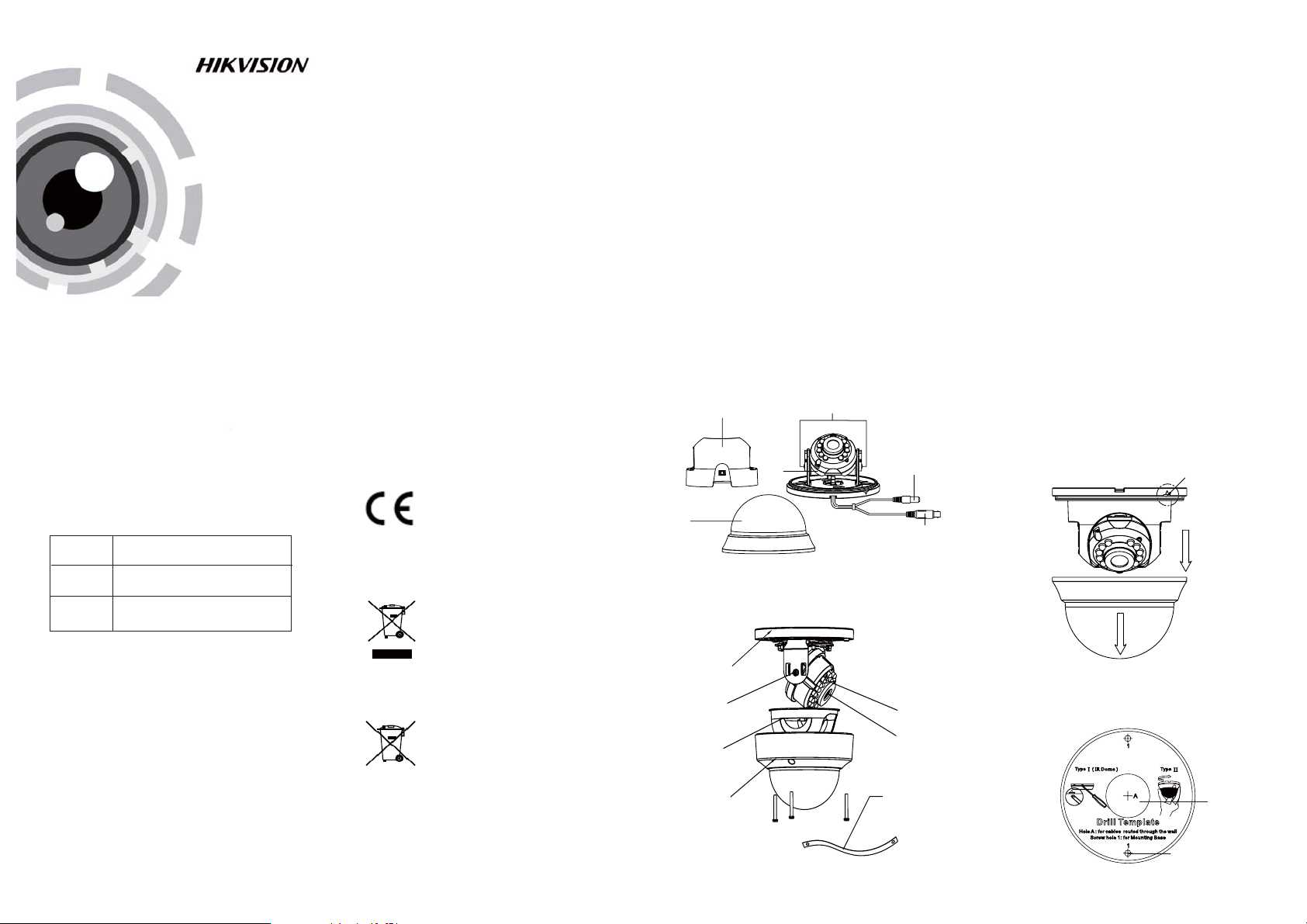
1.2 Overview
1.2.1 Over view of Type I Came ra
Black Liner
Bubble
1.2.2 Over view of Type Came ra
Moungting Base
Adjustment Screw
Black Liner
Bubble
Adjustment Screw
Camera
II
Power Cable
Video Cable
IR LED
Lens
Safety Rope
2 Installation
Before you start:
l Please make s ure th at the d evice in t he p ac kage
is in good condition and all the assembly parts
are i nc lu ded.
l Make su re that all the related e qu ipment i s
power-off during the installation.
l Check the specification of the products for the
installation environment.
l Check whether the power supply is matched
with yo ur pow er o ut pu t to avoid damage.
l Please make sure the wall is strong enough to
withsta nd t hree tim es t he weight of the camera
and the mounting.
l If the wall is the cement wall, you n eed to i ns er t
exp an si on s crews befor e you install the cam era.
If the wall is the wooden wall, you can use
self-tapping screw to secure t he c am era.
l If the product does not function properly,
please contact your dealer or the nearest
service center. Do no t di sassemble the camera
for repair or maintenance by yourself.
2.1 Installation of Type CameraI
Steps:
1.Pry th e sn ap joint u p to remove the bubble
and the black liner.
Figure 2-1 Remove the Bubble
2.Drill the screw holes and cable hole according to
the drill template.
Figure 2-2 The Drill Template
Snap Joint
Cable Hole
Screw Hole
Page 2
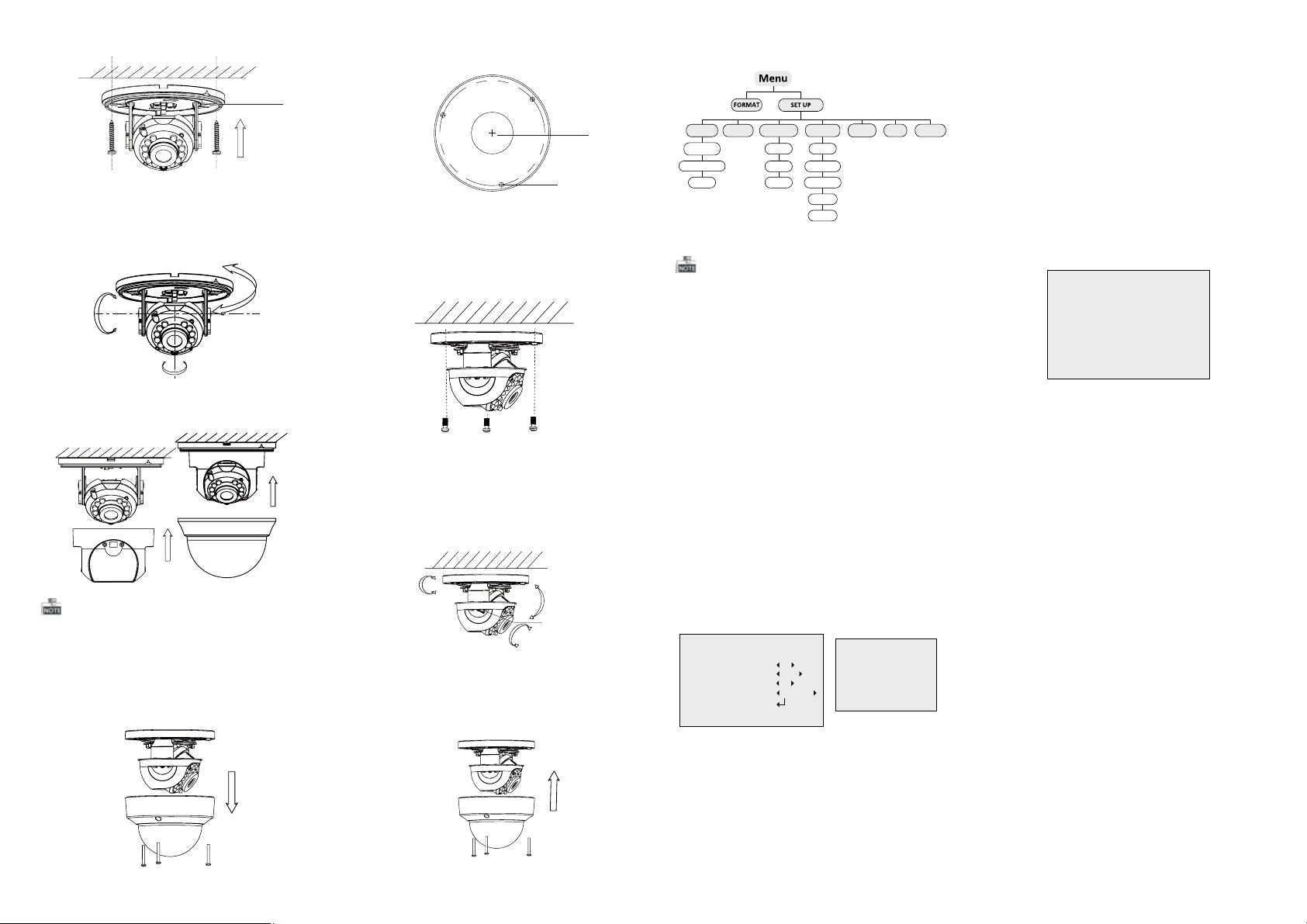
3.Align the base plate w ith the mounting tem pl ate
and secure it with supplied self-tapping screws.
Base Plate
Figure 2-3 Fix the Camera to the Ceiling
4. Route the cables through the cable hole.
5. Connect the corresponding cables.
6. Adjust the camera according to the figure below
to get an o pt im um a ng le .
0 ~350°°
0~70°°
T Direction
P Direction
0~350°°
R Direction
Figure 2-4 3-axis Adjustment
8. Push the black liner and bubble toward t he
camera and buckle them upon to secure them on
the camera.
Figure 2-5 Complete the Installation
Rotate the bubble after completing the
Insta ll ation may change the postion of the lens.
2.2 Installation of Type CameraII
1.Loosen the screws on the bubble to remove the
bubble and the black liner.
Figure 2-6 Remove the Bubble
2.Drill the screw holes and cable hole on the
ceiling according to the supplied drill template.
A
1
1
Cable Hole
Screw Hole
Drill Template
1
HoleA: for cables routed through the ceiling
screw hole 1: for Mounting Base
Figure 2-7 Drill Template
3.Align the base plate with the mounting template
and secure it with supplied self-tapping screws.
Figure 2-8 Fix the Camera to the Ceiling
4. Route the cables through the cable hole.
5. Connect the corresponding cables.
6. Adjust the camera according to the figure below
to get an o pt im um a ng le .
0~75°°
0 ~360°°
T Direction
-15 ~15°°
R Direction
P Direction
T Direction
Adjustment
Screw
Figure 2-9 3-axis Adjustment
8. Fit the black liner and bubble on the camera.
Figure 2-10 Complete the Installation
3 Menu Operation
MODE
5
BLC
5
MIDDLE
VIDEO
SETTING
CONTRAST
SHARPNESS
SATURATION
DNR
MIRROR
MODE MWB
RESET
EXIT
WB
R GIAN 1-|--10
B GAIN 1-|--10
RETURN 8
Figure 3-3 WB
SAVE/EXIT
DAY/NIGHT
WB
AE
BRIGHTNESS
EXPOSURE MODE
AGC
INFRARED
SMART IR
Figure 3-1 Main Menu
With a coaxial camera controller (purchase
separately) or calling the preset No.95 you can
select the menu and adjust the camera parameters.
3.1 FORMAT
You can set the for ma t as PAL/NTSC.
3.2 SET UP
Move th e cu rsor to , and pre ss m enu buttonSET UP
to en ter the S E T U P sub menu.
3.2.1 AE
Move the cursor to AE, and you can adjust the
image brightness by the ,BRIGHTNESS EXPOSURE
MODE AGC, and .
:Brightness
Brightness re fers to the b ri ghtnes s of t he i ma ge .
Exposure Mode:
Move the cursor to , you can selectExposure Mode
the exposure mode between and .Globe BLC
When BLC is selected as the exposure mode, the
level o f B L C mode can be adjusted, as shown in the
Figure 3-2.
EXPOSURE
1.BRIGHTNESS
2.EXPOSURE MODE
LEVEL
3.AGC
4.RETURN
Figure 3-2 EXPOSURE
AGC:
AGC o pt im izes the cla ri ty o f im ag e in p oo r li gh t
scene. AGC leve l ca n be s et a s OF F, LOW, MIDDLE
and HIGH.
3.2.2 WB
Move th e cu rsor to WB, and you can s et W hi te
Balance mode as and in this menuAWB MWB .
AWB: white balance is being adjusted
automatically.
: Set the value from 1 to 1 0.MWB R GAIN/B GAIN
As shown in Figure 3-3.
3.2.3 DAY & NIG HT
Move the cursor to DAY & NIGHT, and select
COLOR B/W SMART, , or as the DAY & NIGHT mode.
COLOR: The image is colore d in d ay m od e al l th e
time.
: The image is black & white all the time, andB/W
the IR LED turns on in the low-light conditions.
: Select to turn on/off the INFRARED_LAMPSMART
and to set th e Sm art IR lev el f rom 1to 16.
As shown in Figure 3-4.
DAY/NIGHT
MODE SMART
INFRARED OFF
SMART IR 0-|--5
RETURN 8
Figure 3-4 DAY/NIGHT
3.2.4 VIDEO SETTING
Contrast:
Contrast enhances the d iffer en ce i n colo r an d li ght
betwe en p ar ts of an image.
You can set the value fro m 1 to .
10
Sharpness:
Sharpness determines the amount of
detail that an imaging system can reproduce.
You can set the value fro m 1 to 10.
Saturation:
You can set the saturatio n level of the image. The
val ue i s from 0 to 10.
DNR:
DNR decreases the noise effect, especially in low
light conditions and delivers more accurate and
sharp image quality. You can set t he val ue f rom
0 to 7.
:Mirror
You can set the Mirror status as H, V, H V, or O F F.
3.2.5 Reset
Res et a ll t he s ettings to the defa ul t.
3.2.6 EXIT
Exit and Save & exit are selectable.
3.2.7 SAVE/EXIT
Move th e cu rsor to , and pre ss O K toSAVE & Ex it
save the settings and exit the menu.
 Loading...