

Page 1
TVI Dome Camera
User Manual
Thank you for purchasing our product. If there
are a ny quest ions, o r reque sts, ple ase do no t
hes itate to c ontact t he deal er.
Thi s manua l may cont ain sev eral tec hnica l
incorrect places or printing errors, and the
content is subject to change without notice.
The u pdate s will be ad ded to th e new ver sion of
this manual. We will readily improve or update
the products or procedures described in the
manual.
0101001051106
UD.6L0201D2128A02
Please refer to the product specification for
camera parameters and functions.
TURBO HD
Privacy Notice
Surveillance laws vary by jurisdiction. Check all
relevant laws in your jurisdiction before using
this product for surveillance purposes to ensure
that your use of this product conforms.
Regulatory Information
FCC Information
FCC compliance: This equipment has been
test ed and fo und to com ply wit h the lim its for a
dig ital de vice, p ursuan t to part 1 5 of the F CC
Rul es. The se limi ts are de signe d to provi de
reasonable protection against harmful
interference when the equipment is operated in
a commercial environment. This equipment
gen erates , uses, a nd can rad iate rad io
frequency energy and, if not installed and used
in accordance with the instruction manual, may
cau se harm ful inte rferen ce to rad io
communications. Operation of this equipment in
a residential area is likely to cause harmful
interference in which case the user will be
req uired to c orrec t the inte rferen ce at his o wn
expense.
FCC Conditions
This device complies with part 15 of the FCC
Rules. Operation is subject to the following two
conditions:
1. Th is devi ce may not c ause ha rmful
interference.
2. This device must accept any interference
received, including interference that may
cau se unde sired op erati on.
EU Conformity Statement
upon the purchase of equivalent new equipment,
or dispose of it at designated collection points.
For more information see:
www.recyclethis.info.
See the product documentation for specific
batt ery inf ormati on. Th e batter y is marke d with
thi s symbo l, whic h may incl ude let tering t o
ind icate ca dmium ( Cd), le ad (Pb) , or merc ury (Hg ).
For p roper re cycli ng, retu rn the ba ttery t o your
supplier or to a designated collection point. For
more information see: www.recyclethis.info.
2012/19/EU (WEE E directive):
Products marked with this symbol
cannot be disposed of as unsorted
municipal waste in the European
Union. For proper recycling, return
this product to your local supplier
This product and - if applicable - the
supplied accessories too are marked
wit h "CE " and com ply ther efore wi th
the applicable harmonized European
stan dards l isted un der the L ow Volta ge Direc tive
2006/95/EC, the E MC Directive 2004/108/EC,
the R oHS Dir ective 2 011/6 5/E U.
This series of camera adopts new generation
sen sor wit h high se nsiti vity an d advan ced circ uit
design technology It features high resolution,.
low i mage di storti on and lo w noise , etc , w hich.
makes it suitable for surveillance system and
image processing system.
l High performance CMOS sensor and high
resolution bring high-quality image;
l Low illumination;
l Support auto white balance, auto gain control,
l Unit transmission control;
l Advanced 3-axis design meets different
installation requirements.
1 Introduction
1.1 Product Features
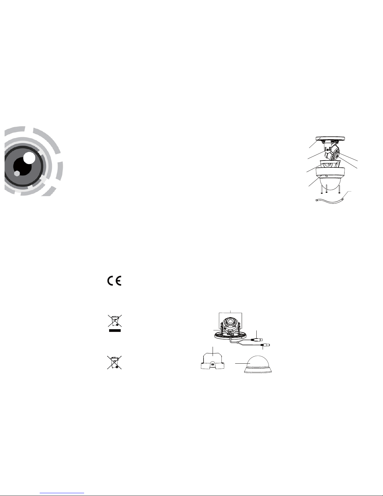
1.2 Overview
1.2 .1 Over view of Ty pe I Came ra
1.2 .2 Over view of Ty pe Came ra
II
2 Installation
Before you start:
l Pl ease ma ke sure th at the dev ice in th e packa ge
is in good condition and all the assembly parts
are included.
l Ma ke sure th at all the r elate d equip ment is
power-off during the installation.
l Ch eck the s pecif icatio n of the pr oduct s for the
installation environment.
l Ch eck whet her the p ower su pply is m atche d
wit h your po wer outp ut to avo id dama ge.
l Please make sure the wall is strong enough to
withstand three times the weight of the camera
and the mounting.
l If t he wall is t he ceme nt wall , you nee d to inser t
exp ansio n screws b efore yo u instal l the cam era.
If the wall is the wooden wall, you can use
sel f-tapp ing scr ew to secu re the ca mera.
l If the product does not function properly,
please contact your dealer or the nearest
ser vice ce nter. Do not d isass emble t he came ra
for repair or maintenance by yourself.
Base Plate
Adjustment Screw
Black Liner
Bubble
IR LED
Lens
Safety Rope
Bubble
Video Cable
Power Cable
Adjustment Screw
Camera
Black Liner
2006/66/EC (battery directive):This
product contains a battery that cannot
be disposed of as unsorted municipal
waste in the European Union.
Industry Canada ICES-003 Compliance
This device meets the CAN I CES-3 (A)/NMB-3(A)
standards requirements.
Page 2
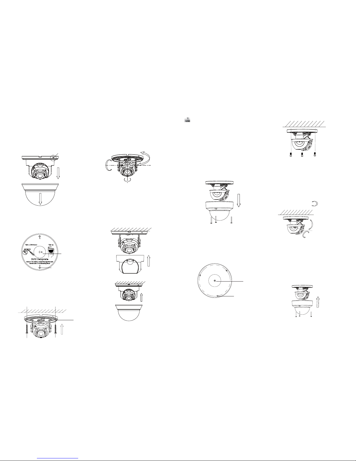
2.2 Installation of Type CameraII
3.Align the base plate with the mounting template
and secure it with supplied self-tapping screws.
4. Route the cables through the cable hole.
5. Connect the corresponding cables.
6. Adjust the camera according to the figure below
to get a n optim um angl e.
7. Push the black liner and bubble toward the
camera and buckle them upon to secure them
on the camera.
Base Plate
P Direction
0 ~350°°
0~70°°
T Direction
Figure 2-4 3-axis Adjustment
Figure 2-5 Complete the Installation
1.Loosen the screws on the bubble to remove the
bubble and the black liner.
Figure 2-6 Remove the Bubble
2.Drill the screw holes and cable hole on the
ceiling according to the supplied drill template.
Drill Template
HoleA: for cables routed through the ceiling
screw hole 1: for Mounting Base
1
1
1
A
Figure 2-7 Drill Template
Screw Hole
Cable Hole
3.Al ign the b ase pla te with th e mount ing tem plate
and secure it with supplied self-tapping screws.
4. Ro ute the ca bles th rough t he cabl e hole.
5. Connect the corresponding cables.
6. Adjust the camera according to the figure below
to get a n optim um angl e.
Figure 2-8 Fix the Camera to the Ceiling
8. Fit the black liner and bubble on the camera.
R Direction
0~75°°
P Direction
0 ~355°°
T Direction
Adjustment
Screw
Figure 2-9 3-axis Adjustment
Figure 2-10 Complete the Installation
0 ~350°°
R Direction
2.1 Installation of Type CameraI
2.Drill the screw holes and cable hole according to
the drill template.
Figure 2-2 The Drill Template
Screw Hole
1.Pry th e snap jo int up to re move th e bubbl e
and t he blac k liner.
Cable Hole
Snap Joint
Figure 2-1 Remove the Bubble
Steps:
Rota te the bu bble af ter comp letin g the
Ins tallat ion may c hange t he posti on of the l ens.
0 ~355°°
 Loading...