

HIKVISION DS-2CE56D1T-AVPIR3, DS-2CE56D1T-AVFIR, DS-2CE56D1T-VPIR3, DS-2CE56D1T-VFIR User Manual
Page 1
TURBO HD
1080P Dome Camera
User Manual
UD.6L0201D1939A01
1.2 Overview
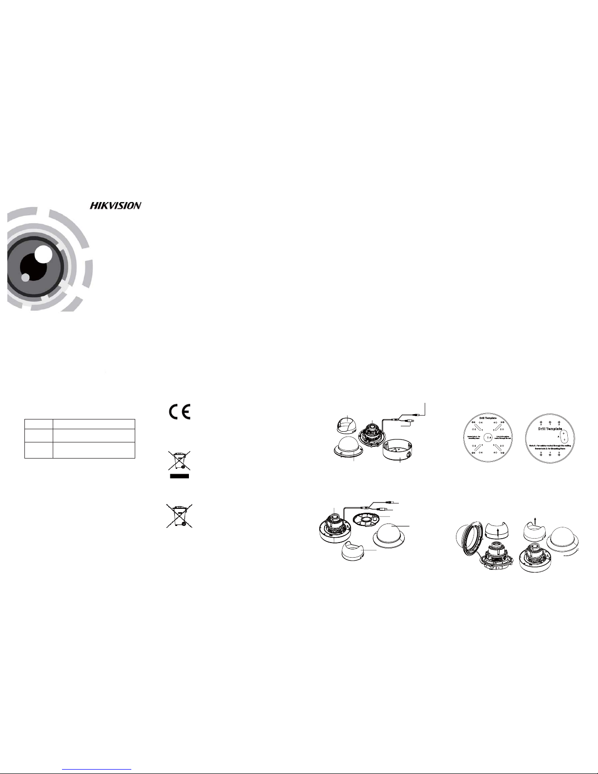
1.2 .1 Over view of Ty pe I Dome C amera
1.2 .2 Over view of Ty pe Dome C amera
II
1 Introduction
1.1 Product Features
This camera adopts new generation sensor with
high sensitivity and advanced circuit board design
technology. It possesses the features of high
resolution, low distortion, and low noise, etc. It is
extremely suitable for supervisory system and
image processing system.
The main features are as follows:
l
High performance CMOS sensor and high
resolution bring high-quality image;
l
Low illumination;
l
Support IR cut filter with auto switch;
l
OSD m enu, pa ramete rs are con figur able;
l
Support auto white balance, auto gain control,
electronic shutter control and internal
synchronization;
l
SMART IR mode;
l
Unit transmission control;
l
Advanced 3-axis design meets different
installation requirements.
l Ple ase make s ure tha t the dev ice in th e packag e
is in good condition and all the assembly parts
are i nclud ed.
l Make s ure tha t all the re lated e quipm ent is
power-off during the installation.
l Che ck the sp ecifi catio n of the pro ducts f or the
installation environment.
l Che ck whet her the p ower su pply is m atched
wit h your po wer outp ut to avo id dama ge.
l Ple ase make s ure the w all is str ong eno ugh to
withstand three times the weight of the camera
and the mounting.
l If th e wall is t he ceme nt wall, y ou need t o inser t
exp ansio n screws b efore yo u instal l the cam era.
If the wall is the wooden wall, you can use
sel f-tap ping sc rew to sec ure the c amera.
l If the product does not function properly,
please contact your dealer or the nearest
ser vice ce nter. Do not d isass emble t he came ra
for repair or maintenance by yourself.
2.1 Ceiling Mounting
Steps:
1.Dr ill the s crew ho les and th e cable h ole on th e
ceiling according to the supplied drill template.
Figure 2-1 The Drill Template
2 Loosen the screws on the bubble of type 1
.
cam era /rot ate the bu bble of t ype2 ca mera to
remove the bubble and the black liner.
Figure 2-2 Remove the Bubble
2 Installation
Before you start:
Fig ure 1-1 O vervi ew of Type I Do me Came ra
Fig ure 1-2 O vervi ew of Type Dom e CameraII
Type I:
Type I :I
Black Liner
Bubble
Powe r Cable
HD Video Cable
Lens
Base plate
Back Box
Lens
Bubble
Black Liner
Power C able
HD Video Cable
Type I :I
Type I:
Regulatory Information
FCC Information
FCC compliance: This equipment has been
tested and found to comply with the limits for a
dig ital de vice, p ursuan t to part 1 5 of the FC C
Rul es. The se limi ts are de signe d to provi de
reasonable protection against harmful
interference when the equipment is operated in
a commercial environment. This equipment
gen erates , uses, a nd can rad iate rad io
frequency energy and, if not installed and used
in accordance with the instruction manual, may
cau se harm ful inte rferen ce to rad io
communications. Operation of this equipment in
a residential area is likely to cause harmful
interference in which case the user will be
req uired to c orrec t the inte rferen ce at his o wn
expense.
FCC Conditions
This device complies with part 15 of the FCC
Rules. Operation is subject to the following two
conditions:
1. Th is devi ce may not c ause ha rmful
interference.
2. This device must accept any interference
received, including interference that may
cause undesired operation.
EU Conformity Statement
upon the purchase of equivalent new equipment,
or dispose of it at designated collection points.
For more information see:
www.recyclethis.info.
2006/66/EC (battery directive):
This product contains a battery that
cannot be disposed of as unsorted
municipal waste in the European
Union.
See the product documentation for specific
batt ery inf ormati on. Th e batter y is marke d with
thi s symbo l, whic h may incl ude let tering t o
ind icate ca dmium ( Cd), le ad (Pb) , or merc ury (Hg ).
For p roper re cycli ng, retu rn the ba ttery t o your
supplier or to a designated collection point. For
more information see: www.recyclethis.info.
2012/19/EU (WEEE directive):
Products marked with this symbol
cannot be disposed of as unsorted
municipal waste in the European
Union. For proper recycling, return
this product to your local supplier
Thi s produ ct and - if a pplica ble - the
supplied accessories too are marked
wit h "CE" an d compl y theref ore with
the applicable harmonized European
stan dards l isted u nder the L ow Volta ge Direc tive
2006/95/EC, the EMC Directive 2004/108/EC,
the RoHS Directive 2011/65/EU.
Tha nk you for p urcha sing ou r produ ct. If th ere
are a ny quest ions, o r reque sts, ple ase do no t
hes itate to c ontact t he deal er.
This manual applies to
Thi s manua l may cont ain sev eral tec hnica l
incorrect places or printing errors, and the
content is subject to change without notice.
The u pdate s will be ad ded to th e new ver sion of
this manual. We will readily improve or update
the products or procedures described in the
manual.
0100001050409
Please refer to the product specification for
camera parameters and functions.
Type
Type
Type
I
II
Model
Privacy Notice
Surveillance laws vary by jurisdiction. Check
all relevant laws in your jurisdiction before using
this product for surveillance purposes to ensure
that your use of this product conforms.
DS-2CE56D1T-AVPIR3/ VPIR3
DS-2CE56D1T-AVFIR/VFIR
Page 2
Steps:
1.Dr ill the s crew ho les and t he cable h ole in th e
ceiling according to the supplied drill template.
2.Screw the bolts through the mount by aligning
wit h the 2 bol t holes . Fit the t oggle s onto the b olts.
3.P ush the t wo togg le bolt s throug h the two s crew
holes on the ceiling. Rotate the bolt till the toggle
holds the ceiling tightly.
2.2 In-ceiling Mounting
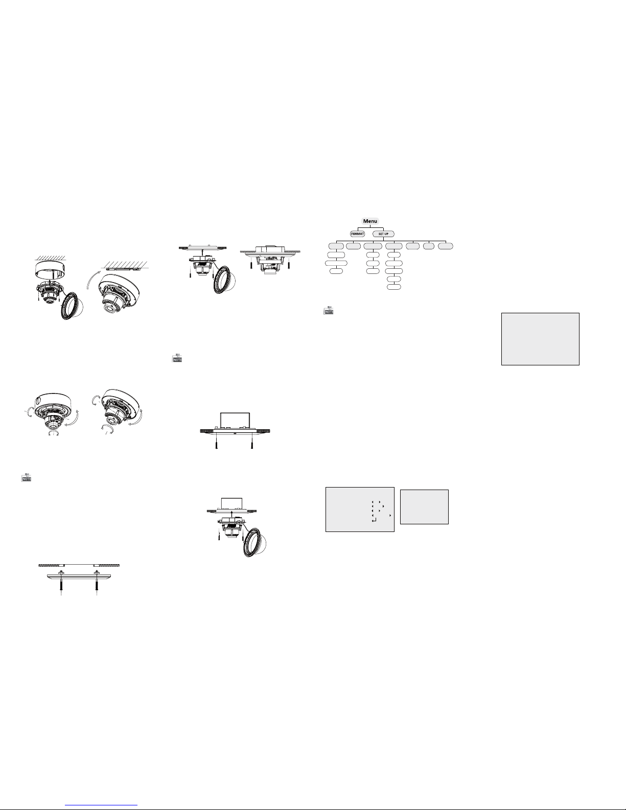
Fig ure 2-5 I nstall t he Moun t
Fig ure 2-6 F ix the Ca mera to th e Mount
Fig ure 2-8 F ix the Ca mera to th e Gang Box
6. Repeat steps 6-8 of the Ceiling Mounting section
to complete the installation.
4.Route and connect the corresponding cables.
5.Fix the camera to the in-ceiling mount with the
supplied screws.
3.Att ach the b ack box of t ype 1 cam era /ba se plate
of type2 camera to the ceiling and secure them
with supplied self-tapping screws.
4.Ro ute the c ables t hroug h the cab le hole .
5.Al ign the c amera wi th the ba ck box/ base pl ate,
and t ighte n the set sc rews to s ecure th e camer a
with the back box/base plate.
Figure 2-3 Fix the Camera to the Ceiling
6. Connect the corresponding cables.
7. Ad just th e camera a ccord ing to the f igure b elow
to get a n optim um angl e.
8. Fi t the bla ck line r on the ca mera and t ighte n the
screws on the bubble of type 1 camera or rotate the
bubble of type 2 camera to complete.
Figure 2-4 3-axis Adjustment
You need to purchase an in-ceiling mount separately
if you adopt in-celling mounting.
2.3 In-ceiling Mounting
in-ceiling mounting with gang box is supported by
the b oth typ es of cam era.
1.Repeat steps 2-3 of the In-ceiling Mounting
section to secure the in-ceiling mount (supplied)
to the gang box.
Fig ure 2-7 I nstall t he Moun t
2.Route and connect the corresponding cables.
3.A lign th e camera w ith the g ang box , and tig hten
the s crews to s ecure t he came ra with th e gang box ..
5. Repeat steps 6-8 of the Ceiling Mounting section
to complete the installation.
Type I:
Type I :I
0~75°°
0 ~355°°
0 ~355°°
P Direction
R Direction
T Direction
Type I:
0°~355°
0~75°°
0 ~340°°
T Direction
R Direction
P Direction
Type I :I
Type I:
Type I :IType I :IType I :I
3.2.2 WB
3.2.1 AE
Move the cursor to AE, and you can adjust the
image brightness by the ,BRIGHTNESS EXPOSURE
MODE AGC, and .
:Brightness
Bri ghtne ss refers t o the bri ghtne ss of the i mage.
Exposure Mode:
Move the cursor to , you can selectExposure Mode
the exposure mode between and .Globe BLC
When BLC is selected as the exposure mode, the
lev el of BL C mode c an be adj usted, a s shown i n the
Figure 3-2.
3.2.4 VIDEO SETTING
Contrast:
Con trast en hance s the dif ferenc e in colo r and lig ht
bet ween pa rts of an i mage.
You can s et the va lue from 1 t o .
10
Sharpness:
Sharpness determines the amount of
detail that an imaging system can reproduce.
You can s et the va lue from 1 t o 10.
Saturation:
You can s et the sa turati on leve l of the im age. Th e
val ue is from 0 t o 10.
DNR:
DNR decreases the noise effect, especially in low
light conditions and delivers more accurate and
sha rp imag e quali ty. You can set t he valu e from
0 to 7.
:Mirror
You can s et the Mi rror sta tus as H, V, H V, or OF F.
3 Menu Operation
Figure 3-1 Main Menu
VIDEO
SETTING
DAY/NIGHT
WB
RESET
BRIGHTNESS
MODE
INFRARED
SMARTIR
CONTRAST
SHARPNESS
SATURATION
EXIT
AE
DNR
MIRROR
EXPOSUREMODE
AGC
SAVE/EXIT
With a coaxial camera controller (purchase
separately) or calling the preset No.95 you can
select the menu and adjust the camera parameters.
3.1 FORMAT
You can s et the fo rmat as PAL /NTSC .
3.2 SET UP
Mov e the curs or to , and p ress me nu butto nSET UP
to en ter the S ET U P sub me nu.
EXPOSURE
1.BRIGHTNESS
2.EXPOSURE MODE
LEVEL
3.AGC
4.RETURN
5
BLC
5
MIDDLE
Mov e the curs or to WB, a nd you can s et Whit e
Balance mode as and in this menuAWB MWB .
AWB: white balance is being adjusted
automatically.
: Set t he valu e from 1 to 10 .MWB R GAIN/B GAIN
As sh own in Fi gure 3- 3.
WB
MODE MWB
R GIAN 1-|--10
B GAIN 1-|--10
RETURN 8
AGC:
AGC o ptimi zes the cl arity o f image i n poor li ght
sce ne. AGC l evel can b e set as OF F, LOW, MID DLE
and H IGH.
Figure 3-2EXPOSURE
Figure 3-3 WB
Figure 3-4 DAY/NIGHT
3.2 .3 DAY & NIGH T
Move the cursor to DAY & NIGHT, and select
COLOR B/W SMART, , or as th e DAY & NIGHT m ode.
COLOR: The i mage is c olored i n day mod e all the
time.
: The im age is bl ack & whi te all th e time, a ndB/W
the I R LED tur ns on in th e low-l ight con ditio ns.
: Select to turn on/off the INFRARED_LAMPSMART
and t o set the S mart IR l evel fro m 1to 16.
As shown in Figure 3-4.
DAY/NIGHT
MODE SMART
INFRARED OFF
SMART IR 0-|--5
RETURN 8
3.2.7 SAVE/EXIT
3.2.5 Reset
Res et all the s ettin gs to the d efault .
3.2.6 EXIT
Exit and Save & exit are selectable.
Mov e the curs or to , and p ress OK toSAVE & E xit
save t he sett ings an d exit th e menu.
 Loading...