

Page 1
TURBO HD
1080P Turret &Bullet Camera
User Manual
Regulatory Information
FCC Information
FCC compliance: This equipment has been
tested and found to comply with the limits for a
dig ital de vice, p ursuan t to part 1 5 of the F CC
Rul es. The se limi ts are de signe d to provi de
reasonable protection against harmful
interference when the equipment is operated in
a commercial environment. This equipment
gen erates , uses, a nd can rad iate rad io
frequency energy and, if not installed and used
in accordance with the instruction manual, may
cau se harm ful inte rferen ce to rad io
communications. Operation of this equipment in
a residential area is likely to cause harmful
interference in which case the user will be
req uired to c orrec t the inte rferen ce at his o wn
expense.
FCC Conditions
This device complies with part 15 of the FCC
Rules. Operation is subject to the following two
conditions:
1. Th is devi ce may not c ause ha rmful
interference.
2. Th is devi ce must a ccept an y inter ferenc e
received, including interference that may
cause undesired operation.
EU Conformity Statement
upon the purchase of equivalent new equipment,
or dispose of it at designated collection points.
For more information see:
www.recyclethis.info.
2006/66/EC (battery directive):
This product contains a battery that
cannot be disposed of as unsorted
municipal waste in the European
Union.
See the product documentation for specific
batt ery inf ormati on. Th e batter y is marke d with
thi s symbo l, whic h may incl ude let tering t o
ind icate ca dmium ( Cd), le ad (Pb) , or merc ury (Hg ).
UD.6L0201D1998A01
2012/19/EU (WEE E directive):
Products marked with this symbol
cannot be disposed of as unsorted
municipal waste in the European
Union. For proper recycling, return
this product to your local supplier
This product and - if applicable - the
supplied accessories too are marked
wit h "CE " and com ply ther efore wi th
the applicable harmonized European
stan dards l isted un der the L ow Volta ge Direc tive
2006/95/EC, the EMC Directive 2004/108/EC,
the R oHS Di recti ve 2011 /65/E U.
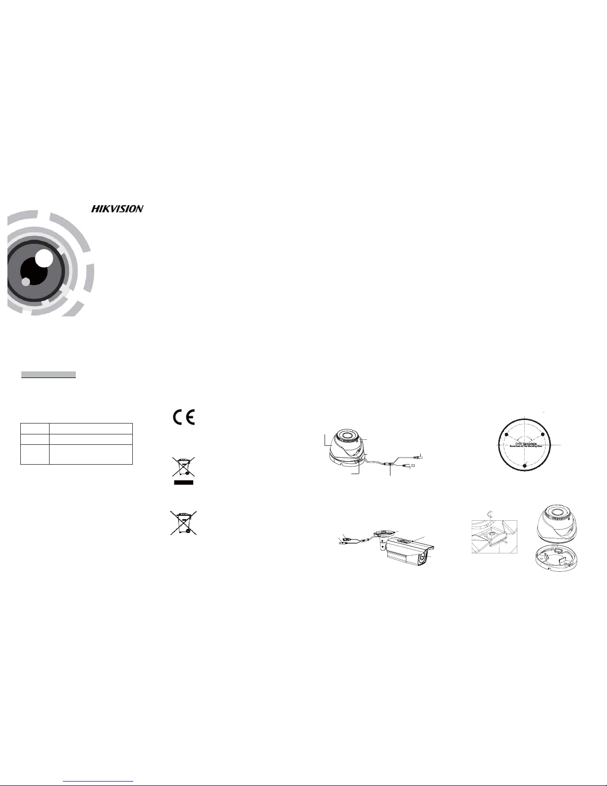
1.2 Overview
1.2 .1 Over view of Ty pe I Came ra
1.2 .2 Over view of Ty pe Came ra
II
HD Video Cable
Enclosure
Lock Button
Mounting Base
Camera
Powe r Cable
1 Introduction
1.1 Product Features
This camera adopts new generation sensor with
high sensitivity and advanced circuit board design
technology. It possesses the features of high
resolution, low distortion, and low noise, etc. It is
extremely suitable for supervisory system and
image processing system.
The main features are as follows:
l
High performance CMOS sensor and high
resolution bring high-quality image;
l
Low illumination;
l
Support IR cut filter with auto switch;
l
OSD menu, parameters are configurable;
l
Support auto white balance, auto gain control,
electronic shutter control and internal
synchronization;
l
SMA RT IR mode;
l
2.8-12mm motorized vari-focal lens;
l
Advanced 3-axis design meets different
installation requirements.
l Ple ase make s ure tha t the dev ice in th e packag e
is in g ood con ditio n and all t he asse mbly pa rts
are i nclud ed.
l Make s ure tha t all the re lated e quipm ent is
power-off during the installation.
l Check the specification of the products for the
installation environment.
l Check whether the power supply is matched
wit h your po wer outp ut to avo id dama ge.
l Please make sure the wall is strong enough to
withstand three times the weight of the camera
and the mounting.
l If th e wall is t he ceme nt wall, y ou need t o inser t
exp ansio n screws b efore yo u instal l the cam era.
If the wall is the wooden wall, you can use
sel f-tapp ing scr ew to secu re the ca mera.
l If the product does not function properly,
please contact your dealer or the nearest
ser vice ce nter. Do not d isass emble t he came ra
for repair or maintenance by yourself.
2.1 Installation of Type CameraI
Steps:
1.Dr ill the s crew ho les and t he cable h ole on th e
ceiling according to the supplied drill template.
Figure 2-1 The Drill Template
2 L oosen t he screw s to remov e the cli p plate a nd
.
take o ut the ma in body.
3.Fix the mounting base to the ceiling with PA4*25
screws.
Fig ure 2-2 Re move th e Clip Pl ate
For p roper re cycli ng, retu rn the ba ttery t o your
supplier or to a designated collection point. For
more information see: www.recyclethis.info.
2 Installation
Before you start:
Thank you for purchasing our product. If there
are a ny quest ions, o r reque sts, ple ase do no t
hes itate to c ontact t he deal er.
This manual applies to
Thi s manua l may cont ain sev eral tec hnica l
incorrect places or printing errors, and the
content is subject to change without notice.
The u pdate s will be ad ded to th e new ver sion of
this manual. We will readily improve or update
the products or procedures described in the
manual.
0100001050305
Fig ure 1-1 O vervi ew of Type I Ca mera
Fig ure 1-2 O vervi ew of Type Cam eraII
Privacy Notice
Surveillance laws vary by jurisdiction. Check all
relevant laws in your jurisdiction before using
this product for surveillance purposes to ensure
that your use of this product conforms.
Please refer to the product specification for
camera parameters and functions.
Type
Type
Type
I
II
Model
DS-2CE 16D1T-AIR3Z
DS-2CE 16D1T-IR3Z
DS-2CE 56D1T-IR3Z
OSD Button
Power C able
Lens
Main Body
Mounting Base
HD Video Cable
Industry Canada ICES-003 Compliance
This device meets the CAN I CES-3 (A)/NMB-3(A)
standards requirements.
Screw Hole
120°
Page 2
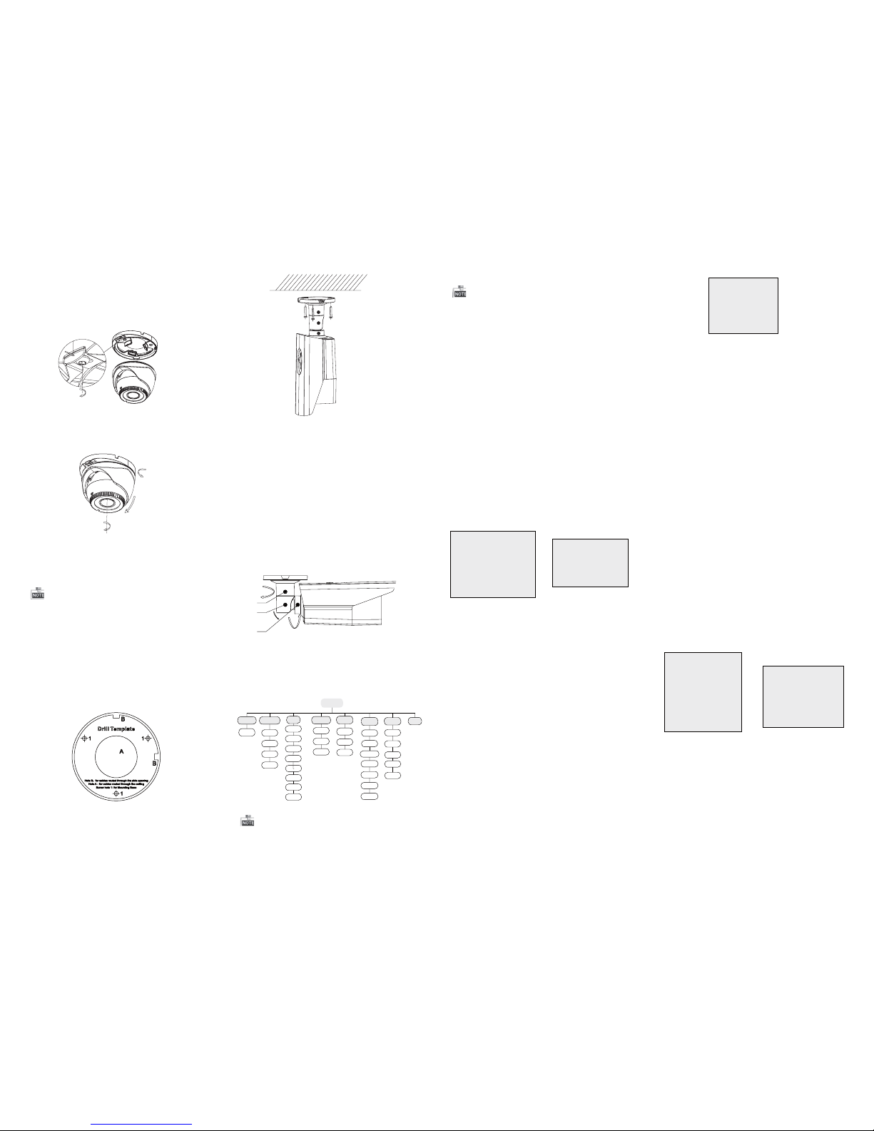
Steps:
1.Dr ill the s crew ho les and t he cable h ole in th e
ceiling according to the supplied drill template.
2.Hammer the supplied plastic expansion bolt into
the s crew ho les.
2.2 Installation of Type II
Camera
Figure 2-5 Drill Template
3.Route the cables to the cable hole and connect
the corresponding cables.
4.Fix the camera to the ceiling with the supplied
screws.
4.Route the cables to the cable hole and connect
the corresponding cables.
5.Install the main body onto the mounting plate
and i nsert t he clip p late.
6.Tig hten th e screws w ith the w rench .
Fig ure 2-4 3 -axis Ad justm ent
0 ~360°
0 ~75°
0~360°
Both wall mounting and ceiling mounting are
suitable for type bullet camera. Ceiling mounting
wil l be taken a s an examp le in the s ectio n. And yo u
can take steps of ceiling mounting as a reference
if wall mounting is adopted.
360°
90°
360°
1
2
3
Figure 2-6 Fix the Camera to the Ceiling
5. Adjust the surveillance angle.
1). Loosen No.1 adjusting screw to adjust the pan
position (0 ~ 360 ).°°
2).Tighten No.1 adjusting screw.
3). Loosen No.2 adjusting screw to adjust the
tilting position(0 ~ 90 ).°°
4).Tighten No.2 adjusting screw.
5). Loosen No.3 adjusting screw to adjust the
rotation position 0 ~ 360 .(° °)
6).Tighten No.3 adjusting screw.
Figure 2-7 3-axis Adjustment
3.3 DAY/NI GHT
Color, B/W, AUTO and EXT are selectable for DAY/
NI GHT swi tches. U nder th e mode of t he AU TO and
EX T, you can se t the I R LED as Sm art and C DS. I f the
IR LED is selected as Smart, you can set the brightnes s of the I R LE D.
3.4 AWB
Figure 3-2 DAY/NI GHT
Figure 3-3 AWB
SPECIAL
1. PRIVACY ZONE
2. MOTION
3. HLC
4. RETURN RET
Figure 3-4 SPECIAL
Motion: Set t he Moti on statu s as O N or OF F. Set
the S EN SIT IVI TY fr om 0 to 255 . Set the a larm sta tus
as I CON /TR ANC E/O FF. Set t he hold t ime from
0 second to 255 seconds.
HLC: HLC supplements the brightness of the
per iphera l area of t he imag e. You can se t the mas k
val ue and th reshol d from 0 to 2 55.
Privacy zone: Select a PRIVA CY area. Set the
MASK PAT asOFF,GRAY, WHITE orBLACK. Set the
SX /EX /SY/E Y valu e to defi ne the po sitio n and siz e
of the area.
DAY/NIGHT
1. MODE AUTO
2. D TO N 63
3. N TO D 63
4. DELAY TIME 20
5. RETURN RET
AWB
1. MODE AUTO
2. R-G GAIN 255
3. B-G GAIN 151
4. RETURN RET
Aut o, User, Pus h, 8000 k, 6000 k, 4200 k and 300 0k
are selectable for AWB. Under the mode of AUTO,
you need to set the R-G/B-G Gain and to select an
indoor/outdoor mode. If the AWB mode is select
as Us er, Yo u need to se t the R/G /B Gain m anual ly.
3.5 AE
You can s et the A E mode a s HOL D, DC a nd ES C.
: Brightness refers to the brightnessBrightness
of th e image .
: Shu tter den otes th e speed o f the shu tter.Shutter
You can s et the sh utter as AU TO, 1/2 5, 1/30 , 1/50,
1/60, 1/100, 1/120, 1/250, 1/500, 1/1k, 1/3k and
1/10k.
: You can s et the fl icker st atus as 5 0HZ/ 60H ZFlicker
to prevent image flicking.
: BLC bases on the back area to enhance theBLC
bri ghtne ss of the w hole im age. You ca n set the
BL C gain fr om 0 to 16.
: AG C opti mizes t he clar ity of im age in po orAGC
lig ht scen e. The val ue of A GC can b e set from 1 -5.
: LSC corrects the phenomenon where theLSC
ima ge gets da rkene d or blur red on the p eriph ery.
3.6 SP ECI AL
SYSTEM
1. CAMERA ID 255
2. ID DISP. ON
3. NAME DISP. ON
4. LANGUAGE ENG
5. FACTORY INIT OFF
6. RETURN RET
3.8 SYSTEM
You can s et the ca mera I D from 0 to 2 55.
Select the ID display and name display status as
ON/OFF.
Chinese and English are selectable for the language
of the menu.
You can r estore t he came ra to the de fault by
setting the factory initialization status as ON.
3.9EXIT
Exit and Save & exit are selectable.
EFFECT
1. COLOR GAIN 200
2. COLOR HUE 200
3. SHARPNESS 25
4. CONTRAST 150
5. BRIGHT OFF. 1
6. MIRROR ON
7. FLIP ON
8. RETURN RET
Color Gain: Color gain adjust this feature to change
the s aturat ion of th e color. You ca n set the va lue
fro m 0 to 255.
: You can adjust the image HUE fromColor Hue
0 to 71 .
: Sha rpnes s deter mines t he amou nt ofSharpness
detail that an imaging system can reproduce.
You can s et the va lue from 0 t o 255.
: Contrast enhances the difference inContrast
col or and li ght betw een par ts of an im age.
You can s et the va lue from 0 t o 255.
: Bri ght Off. re fers to the b right nessBright Off.
com pensa tion of t he image . You can set t he brig ht
compensation value as 0 or 1.
: You can s et the Mi rror sta tus as O N/O FF.Mirror
: You can s et the F LIP s tatus a s ON/ OFF.Flip
3.7EFFECT
Figure 3-5 EFFECT
Figure 3-6 SYSTEM
Figure 3-1 Main Menu
Menu
AE
AWB
DAY&NIGHT
SYSTEM
SPECIAL
EFFECT
DC
ESC
HOLD
FRAME
RATE
AUTO
USER
HOLD
8000K
6000K
COLOR
B/W
AUTO
CAMERA
ID
IDDISP
PRIVACY
ZONE
MOTION
HLC
LANGUAGE
COLOR
GAIN
COLOR
HUE
SHARPNESS
EXIT
VIDEO.OUT
4200K
3200K
CONTRAST
BRIGHT
MIRROR
FLIP
NAME
DISP
FACTORY
INIT
EXT
PUSH
A coaxial camera controller (purchase separately)
is required to select the menu and adjust the
camera param eters.
3.2 VIDEO.OUT
You can s et the fr ame rate a s 25 fps/ 30fps.
3 Menu Operation
3.1 Smart Focus
Pre ss the me nu butto n to enter t he menu i nterf ace.
Whe n the men u interf ace is no t displ ayed, yo u can
pre ss and ho ld any dir ectio n key of the j oysti ck
for 3s t o enter t he focus ing int erface . Move th e
joystick to adjust the camera lens by the FOCUS +,
FOCUS-,ZOOM+ andZOOM-.
After connecting the camera with back-end device,
you c an also co ntrol t he came ra with mo use in P TZ
con trol mod e. The di recti on keys wo rks as the m enu
joystick.
7.Ad just th e camera a ccord ing to the f igure b elow
to get a n optim um angl e.
Fig ure 2-3 I nstall t he Turret C amera
 Loading...