

HIKVISION DS-2CE56D1T-VFIR3, DS-2CE56C2T-VFIR3, DS-2CE16C2T-VFIR3, DS-2CE16D1T-VFIR3 User Manual
Page 1
TVI
Turret & Bullet Camera
User Manual
Thank you fo r purchasing our product. If there
are a ny quesons, or r equests, please do not
hes itate to c ontact the dea ler.
This manual ma y contai n severa l technical
incorrect places or prin ng errors, and the
con tent is subject to chang e without noce.
The updates w ill be added to the n ew versi on of
this manual. We will readily improv e or update
the products o r procedures described in the
manual.
Regulato ry Info rmaon
FCC I nformaon
FCC compliance: This equipmen t has been
teste d and found to comply with the limits for a
digita l device, pursuan t to part 15 of the FC C
Rules. Thes e limits ar e designed to pr ovide
reasonable p rotecon against harm ful
int erference whe n
the equ ipment is o perate d in
a comme rcial en vironme nt. This equipmen t
gen erates , uses, a nd can radia te radio
frequency energ y and, if not installed and used
in acco rdance with the instrucon manual, may
cause ha rmful interf erence to radio
communicaons. Oper aon of this equipment in
a residenal a rea is likely to c ause harmful
int erference in which cas e the user will be
requi red to cor rect the int erference at h is own
expense.
FCC Condions
This device complies with part 1 5 of the FCC
Rul es. Operaon is s ubject to the fol lowin g two
condions:
1. Th is device m ay not cause harm ful
int erference.
2. This de vice must accept any int erference
received, including in terference
that may
cause undesired oper aon.
EU Conf ormity Statemen t
upon the purchase of equivalent new equipment,
or dispose of i t at designated collection points.
For more information see:
www.recycle this.info.
2006/66/EC (baery dir ecve):
This product co ntains a ba ery that
cannot be disposed o f as unsorted
municipal waste i n the European
Union.
See the product document aon for specific
bae ry info rmaon. The b aery is mar ked with
this sy mbol, which m ay include le ering to
indic ate cadmium (Cd), lea d (Pb), or mercur y (Hg).
For p roper recy cling, retur n the baer y to your
supplier or to a designa ted collecon point. F or
more informa on see: www.recyclethis.info .
2012/19/EU (WEEE direcve):
Products marke d with this symbol
cannot be disposed o f as unsorted
municipal waste in the European
Union. For proper recy cling, return
this product to your local supplier
Please refe r to the product specificaon fo r
camera parame ters and funcons.
This pr oduct and - if applicable - the
supplie d accessories too are mar ked
wit h "CE" and comply the refore with
the applicable harmonized Eur opean
standard s listed under the L ow Volta ge Direcv e
2006/95/EC, the EMC Direcve 2004/108/EC ,
the RoHS Direcve 2011/65/EU.
TURBO HD
This series o f camera adopts n ew gene raon
sensor with high sensivity and advanced circuit
design technology It fea tures high resoluon,.
low i mage distor on and low nois e, etc , w hich.
make s it suitable fo r surveilla nce syste m and
ima ge processing sy stem.
High performance CMOS sensor and high
resoluon bring high-quality imag e;
Low illuminaon;
OSD m enu, parameter s are configu rable;
Support auto white balance, auto g ain control,
electronic shuer c ontrol;
Support image effe ct adjustment;
Unit transmission co ntrol;
Advanced 3- axis desig n meets diff erent
ins talla on require ments.
1 Introducon
1.1 Product Features
2 Installaon
Check t he spec ificao n of the products fo r the
installa on environment .
Check whether the pow er supply is matc hed
with your p ower output to av oid damage.
Please make sur e the wal l is stron g enough to
withstand thre e mes the weigh t of the camera
and the mounng.
If the wa ll is the cement w all, you need t o insert
expansio n screws befo re you in stall th e camera.
If the wall i s the wooden wall, you ca n use
self-tappi ng screw to se cure the camer a.
If the pr oduct does not funcon properly,
please con tact your dealer or the nearest
ser vice center. Do not di sassemble the c amera
for repair o r maintenance by yourself.
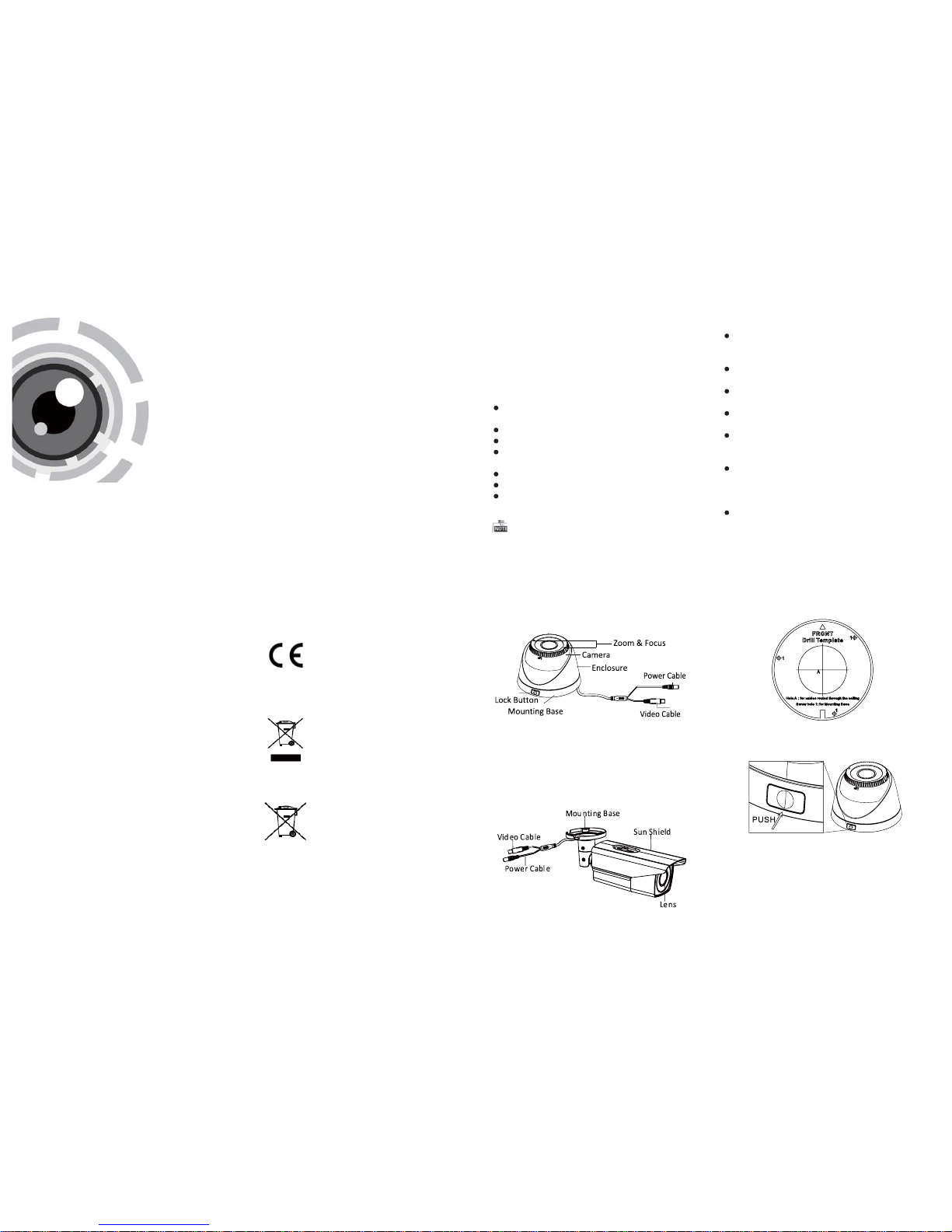
1.2 Ove rview
1.2.1 Ove rview o f Type I Camera
1.2.2 Ove rview o f Type Camera
II
Figure 1 -1 Over view of Type I Came ra
Figure 1 -2 Over view of Type CameraII
2.1 Installaon of Type CameraI
Ste ps:
1.Drill the screw holes and the cable hole on the
ceiling according t o the supplied drill template .
Figure 2-1 The Drill Template
2 Push the lock bu on to disasse mble the camer a
.
fro m the mounng base.
Figur e 2-2 Release The Loc k Screw
Please make s ure tha t the device in the packa ge
is in g ood condion and all the assembly parts
are i ncluded.
Make sur e that al l the relate d equipment is
power-off during the ins tallaon.
3.Fix the mounng base t o the ceiling.
Befor e you start :
Cameras in some models d o not support OSD
menu. F or actual opera on, please refer to the
specificaon o f each model.
4.Route the c ables to the cable hole and connect
the corresponding cables.
5.Secure the camer a to the mounng base by
supplied screws . Keep the word UP o n the camera
being uprigh t during the in stallao n to make the
image showing normally.
Page 2
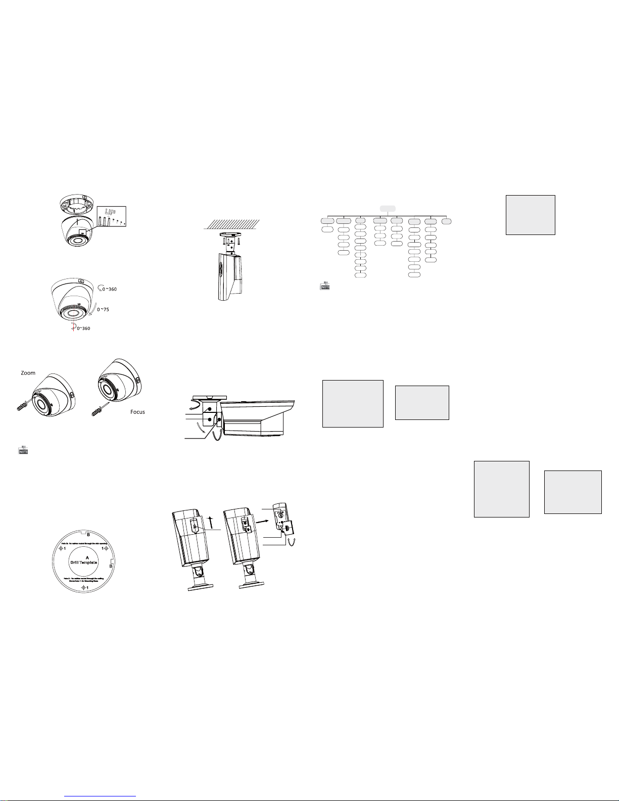
Figure 2-4 Universal Adjustment
6.Adjust the camera according to the figure below
to get a n optim um angl e.
Fig ure 2-3 S ecure th e Camer a
7.Us e the scr ewdriv er to adj ust the ZO OM scre w
and t he FOCU S screw un til you g et the opt imum
image.
Fig ure 2-5 Zo om and Fo cus Adj ustme nt
2.2 Installation of Type II
Camera
Both wall mounting and ceiling mounting are
suitable for type bullet camera. Ceiling mountingII
wil l be taken a s an examp le in the s ectio n. And yo u
can take steps of ceiling mounting as a reference
if wall mounting is adopted.
Steps:
1.Dr ill the s crew ho les and t he cable h ole in th e
ceiling according to the supplied drill template.
2.Hammer the supplied plastic expansion bolt into
the s crew ho les.
Figure 2-6 Drill Template
3.Route the cables to the cable hole and connect
the corresponding cables.
4.Fix the camera to the ceiling with the supplied
screws.
Figure 2-7 Fix the Camera to the Ceiling
Figure 2-8 3-axis Adjustment
5. Adjust the surveillance angle.
1). Loosen No.1 adjusting screw to adjust the pan
position (0 ~ 360 ).°°
2).Tighten No.1 adjusting screw.
3). Loosen No.2 adjusting screw to adjust the
tilting position(0 ~ 90 ).°°
4).Tighten No.2 adjusting screw.
5). Loosen No.3 adjusting screw to adjust the
rotation position 0 ~ 360 .(° °)
6).Tighten No.3 adjusting screw.
0~360
0~360
1
2
3
0~90
3.2DAY/NIGHT
Color, B/W,A UTO and EXT are selectable for DAY/
NIG HT switches. Under the mode of the AUTO and
EX T, you can se t the I R LED as Sma rt and C DS. I f the
IR LED is selected as Smart, you can set the brightness of the IRLED.
3.3.3 AWB
Figure 3-2DAY/NIGHT
Figure 3-3 AWB
SPECIAL
1. PRIVACY ZONE
2. MOTION
3. HLC
4. RETURN RET
Figure 3-4SPECIAL
Motion: Set t he Moti on statu s as O N or OF F. Set
the S EN SIT IVI TY fr om 0 to 255 . Set the a larm sta tus
as I CON /TR ANC E/O FF. Set t he hold t ime from
0 second to 255 seconds.
HLC: HLC supplements the brightness of the
per iphera l area of t he imag e. You can se t the mas k
val ue and th reshol d from 0 to 2 55.
Privacy zone: Select a PRIVAC Yarea. Set the
MASK PATas OFF, GRAY, WHITEor BLACK. Set the
SX /EX /SY/E Y valu e to defi ne the po sitio n and size
of the area.
DAY/NIGHT
1. MODE AUTO
2. D TO N 63
3. N TO D 63
4. DELAY TIME 20
5. RETURN RET
AWB
1. MODE AUTO
2. R-G GAIN 255
3. B-G GAIN 151
4. RETURN RET
Aut o, User, Pus h, 8000 k, 6000 k, 4200 k and 300 0k
are selectable for AWB. Under the mode of AUTO,
you need to set the R-G/B-G Gain and to select an
indoor/outdoor mode. If the AWB mode is select
as Us er, You ne ed to set t he R/G/ B Gain ma nuall y.
3.3.4 AE
You can s et the A E mode a s HOL D, DC a nd ES C.
: Bri ghtne ss refers t o the bri ghtne ssBrightness
of th e image .
: Shu tter den otes th e speed o f the shu tter.Shutter
You can s et the sh utter as AU TO, 1/2 5, 1/30 , 1/50,
1/60, 1/100, 1/120, 1/250, 1/500, 1/1k, 1/3k and
1/10k.
: You can s et the fl icker st atus as 5 0HZ/ 60H ZFlicker
to prevent image flicking.
: BLC bases on the back area to enhance theBLC
bri ghtne ss of the w hole im age. You ca n set the
BL C gain fr om 0 to 16.
: AG C opti mizes t he clar ity of im age in po orAGC
lig ht scen e. The val ue of AG C can b e set from 1 -5.
: LSC corrects the phenomenon where theLSC
ima ge gets da rkene d or blur red on the p eriph ery.
3.3.5 SP ECIA L
SYSTEM
1. CAMERA ID 255
2. ID DISP. ON
3. NAME DISP. ON
4. LANGUAGE ENG
5. FACTORY INIT OFF
6. RETURN RET
3.3.7 SYSTEM
You can s et the ca mera I D from 0 to 2 55.
Select the ID display and name display status as
ON/OFF.
Chinese and English are selectable for the language
of th e menu.
You can r estore t he came ra to the de fault by
setting the factory initialization status as ON.
3.3.8 EXIT
Exit and Save & exit are selectable.
EFFECT
1. COLOR GAIN 200
2. COLOR HUE 200
3. SHARPNESS 25
4. CONTRAST 150
5. BRIGHT OFF. 1
6. MIRROR ON
7. FLIP ON
8. RETURN RET
Color Gain: Color gain adjust this feature to change
the s aturat ion of th e color. You ca n set the va lue
fro m 0 to 255.
: You can adjust the image HUE fromColor Hue
0 to 71 .
: Sha rpnes s deter mines t he amou nt ofSharpness
detail that an imaging system can reproduce.
You can s et the va lue from 0 t o 255.
: Contrast enhances the difference inContrast
col or and li ght betw een par ts of an im age.
You can s et the va lue from 0 t o 255.
: Bri ght Off. re fers to the b right nessBright Off.
com pensa tion of t he image . You can set t he brig ht
compensation value as 0 or 1.
: You can s et the Mi rror sta tus as O N/O FF.Mirror
: You can s et the F LIP s tatus a s ON/ OFF.Flip
3.3.6 EFFECT
Figure 3-5 EFFECT
Figure 3-6 SYSTEM
3 Menu Operation
Figure 3-1 Main Menu
Menu
AE
AWB
DAY&NIGHT
SYSTEM
SPECIAL
EFFECT
DC
ESC
HOLD
FRAME
RATE
AUTO
USER
HOLD
8000K
6000K
COLOR
B/W
AUTO
CAMERA
ID
IDDISP
PRIVACY
ZONE
MOTION
HLC
LANGUAGE
COLOR
GAIN
COLOR
HUE
SHARPNESS
EXIT
VIDEO.OUT
4200K
3200K
CONTRAST
BRIGHT
MIRROR
FLIP
NAME
DISP
FACTORY
INIT
EXT
PUSH
A coaxial camera controller (purchase separately)
is required to select the menu and adjust the
camera param eters.
3.1 VIDEO.OUT
You can s et the fr ame rate a s 25 fps/ 30fps.
6.Push the focus &zoom adjustment cover upward
to move it aside.
7.Use the cover as a screwdriver to adjust the ZOOM
scr ew and th e FOCUS sc rew unt il you get t he
optimum image.
Cover
Focus
Zoom
0~360
Cover
Figure 2-9 Zoom and Focus Adjustment
 Loading...