

Page 1
TVI Bullet&Turret Camera
User Manual
Thank you for purchasing our product. If there
are a ny quest ions, o r reque sts, ple ase do no t
hes itate to c ontact t he deal er.
This manual applies to
Thi s manua l may cont ain sev eral tec hnica l
incorrect places or printing errors, and the
content is subject to change without notice.
The u pdate s will be ad ded to th e new ver sion of
this manual. We will readily improve or update
the products or procedures described in the
manual.
0100001050227
1.2 Overview
UD.6L0201D1806A01
Please refer to the product specification for
camera parameters and functions.
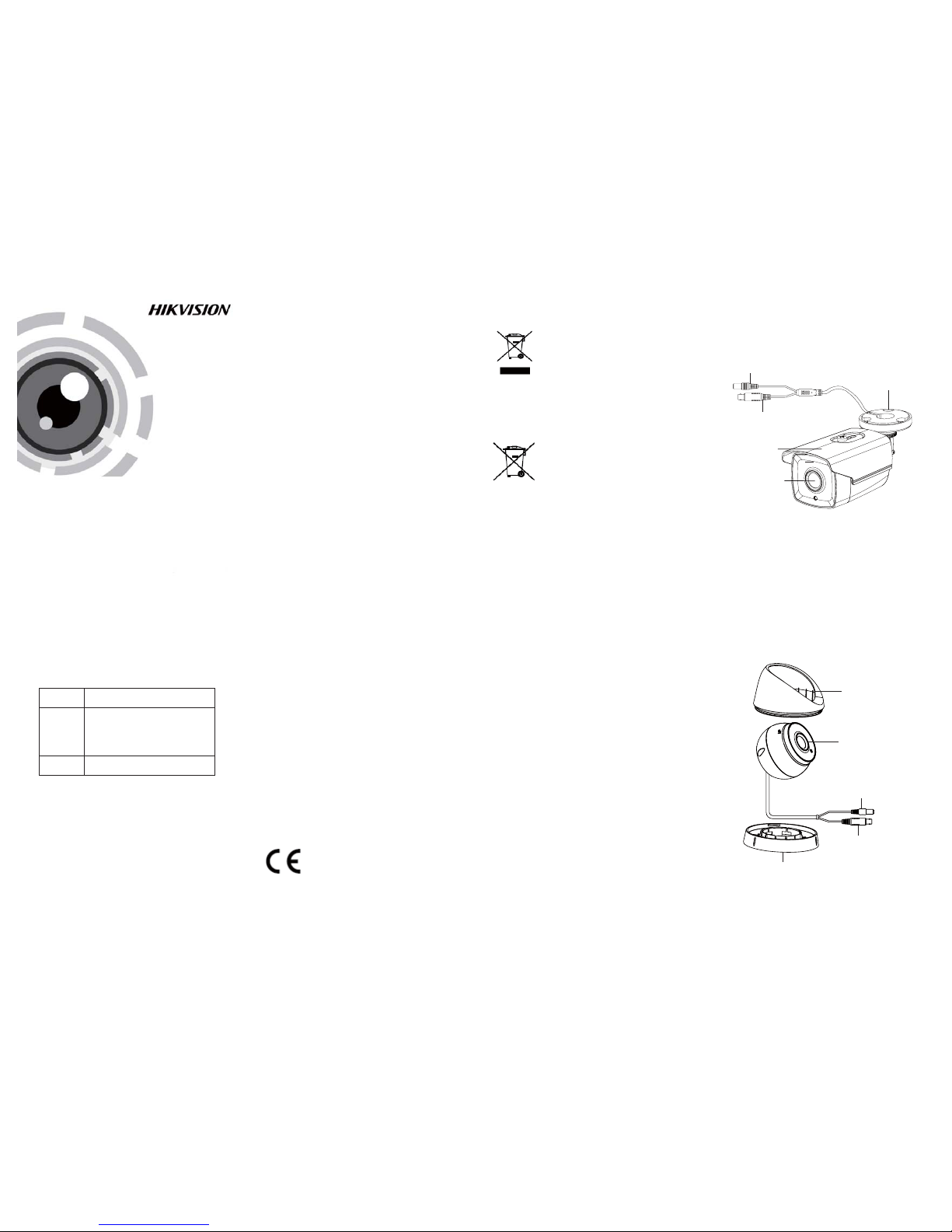
1.2 .1 Over view of Ty pe I Came ra
1.2 .2 Over view of Ty pe Came ra
II
HD Video Cable
Powe r Cable
Enclosure
Camera
HD Video Cable
Powe r Cable
Mounting Base
TURBO HD
Type
Type
Type
I
II
Model
DS-2C E16C0T-IT1
DS-2C E16C0T-IT3
DS-2C E16C0T-IT5
DS-2C E56C0T-IT3
Sun Shield
Mounting Base
Lens
Regulatory Information
FCC Information
FCC compliance: This equipment has been
test ed and fo und to com ply wit h the lim its for a
dig ital de vice, p ursuan t to part 1 5 of the F CC
Rul es. The se limi ts are de signe d to provi de
reasonable protection against harmful
interference when the equipment is operated in
a commercial environment. This equipment
gen erates , uses, a nd can rad iate rad io
frequency energy and, if not installed and used
in accordance with the instruction manual, may
cau se harm ful inte rferen ce to rad io
communications. Operation of this equipment in
a residential area is likely to cause harmful
interference in which case the user will be
req uired to c orrec t the inte rferen ce at his o wn
expense.
FCC Conditions
This device complies with part 15 of the FCC
Rules. Operation is subject to the following two
conditions:
1. Th is devi ce may not c ause ha rmful
interference.
2. Th is devi ce must a ccept an y inter ferenc e
received, including interference that may
cause undesired operation.
EU Conformity Statement
upon the purchase of equivalent new equipment,
or dispose of it at designated collection points.
For more information see:
www.recyclethis.info.
2006/66/EC (battery directive):
This product contains a battery that
cannot be disposed of as unsorted
municipal waste in the European
Union.
See the product documentation for specific
batt ery inf ormati on. The b atter y is marke d with
thi s symbo l, whic h may incl ude let tering t o
ind icate ca dmium ( Cd), le ad (Pb) , or merc ury (Hg ).
For p roper re cycli ng, retu rn the ba ttery t o your
supplier or to a designated collection point. For
more information see: www.recyclethis.info.
Thi s serie s of came ra adopt s new gen eratio n
sensor with high sensitivity and advanced circuit
design technology It features high resolution,.
low i mage di storti on and lo w noise , etc , whic h.
makes it suitable for surveillance system and
image processing system.
l High performance CMOS sensor and high
resolution bring high-quality image;
l Low illumination;
l Support auto white balance, auto gain control,
electronic shutter control;
l Unit transmission control;
l Advanced 3-axis design meets different
installation requirements.
1 Introduction
1.1 Product Features
2012/19/EU (WEE E directive):
Products marked with this symbol
cannot be disposed of as unsorted
municipal waste in the European
Union. For proper recycling, return
this product to your local supplier
Please refer to the product specification for
camera parameters and functions.
This product and - if applicable - the
supplied accessories too are marked
wit h "CE " and com ply ther efore wi th
the applicable harmonized European
stan dards l isted un der the L ow Volta ge Direc tive
2006/95/EC, the E MC Directive 2004/108/EC,
the RoHS Directive 2011/65/EU.
Surveillance laws vary by jurisdiction. Check all
relevant laws in your jurisdiction before using
this product for surveillance purposes to ensure
that your use of this product conforms.
Privacy Notice
Fig ure 1-1 O vervi ew of Type I Camera
Fig ure 1-2 O vervi ew of Type II Came ra
Page 2
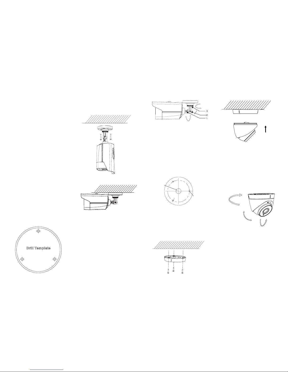
2.2 Installation of Type II Camera
1.Drill the screw holes and the cable hole on the
ceiling according to the supplied drill template.
Steps:
Figure 2-4 The Drill Template
Fig ure 2-5 F ix the Mo unting B ase and C amera
2.Fix the mounting base to the ceiling with the
supplied screws.
3.Ro ute the ca bles to t he cabl e hole an d connec t
corresponding power cable and video cable.
4.Se cure th e camera t o the mou nting b ase.
5.
Adjust the camera according to the figure below
to get a n optim um angl e.
0 ~360°°
0~75°°
0 ~360°°
Figure 2-6 3-axis Adjustment
Screw Hole
Cable Hole
2.1 Installation of Type CameraI
Steps:
1.Drill the screw holes in the ceiling according
to the supplied drill template.
2.Hammer the supplied plastic expansion bolt into
the s crew ho les.
Figure 2-1 Drill Template
All S crew Ho les: for
mounting base
3.Route the cables to the cable hole and connect
the corresponding power cable and video cable.
4.Fix the camera to the ceiling with the supplied
screws.
Figure 2-2 Fix the Camera to the Ceiling
5.Adjust the surveillance angle.
1).Loosen No.3 adjusting screw to adjust the
panning position 0 ~ 360 .(° °)
.2).Tighten No.3 adjusting screw
3).Loosen the No.2 adjusting screw to adjust the
tilting position 0 ~ 90(° °).
4).Tighten No.2 adjusting screw.
5).Loosen No.1 adjusting screw to adjust the
azimuth angle of the image 0 ~ 360(° °).
.6).Tighten No.1 adjusting screw
Figure 2-3 3-axis Adjustment
2 Installation
Before you start:
l Ple ase mak e sure tha t the dev ice in th e packa ge
is in good condition and all the assembly parts
are i nclud ed.
l Mak e sure tha t all the r elated e quipm ent is
power-off during the installation.
l Che ck the sp ecifi catio n of the pr oduct s for the
installation environment.
l Che ck whet her the p ower su pply is m atched
wit h your po wer outp ut to avo id dama ge.
l Please make sure the wall is strong enough to
withstand three times the weight of the camera
and the mounting.
l If th e wall is t he ceme nt wall , you need t o inser t
exp ansio n screws b efore yo u instal l the cam era.
If the wall is the wooden wall, you can use
sel f-tapp ing scr ew to secu re the ca mera.
l If the product does not function properly,
please contact your dealer or the nearest
ser vice ce nter. Do not d isass emble t he came ra
for repair or maintenance by yourself.
360°
90°
360°
 Loading...