

Page 1
1 Introduction
1.1 Product Features
1.2 Overview
Fig ure 1-2 O vervi ew of Type Cam eraII
2 Installation
Before you start:
1.3 Mega Pixel Camera
User Manual
Thank you for purchasing our product. If there
are a ny quest ions, o r reque sts, ple ase do no t
hes itate to c ontact t he deal er.
This manual applies to 3DS-2CE15F5P(N)-VFIR ,
DS-2CE55F5P(N)-VFIR3.
Thi s manua l may cont ain sev eral tec hnica l
incorrect places or printing errors, and the
content is subject to change without notice.
The u pdate s will be ad ded to th e new ver sion of
this manual. We will readily improve or update
the products or procedures described in the
manual.
DISCLAIMER STATEMENT
Underwriters Laboratories Inc. (”UL” has not)
tested the performance or reliability of the
security or signaling aspects of this product.
UL ha s only te sted for f ire, sho ck or cas ualty
haz ards as ou tline d in Ul’s St andard (s) for S afety,
UL6 0950- 1. UL Cer tific ation d oes not co ver the
performance or reliability of the security or
signaling aspects of this product. UL MAKES NO
REPRESENTATIONS, WARRANTIES OR
CERTIFICATIONS WHATSOEVER REGARDING
0100001031213
Regulatory Information
FCC Information
FCC compliance: This equipment has been
tested and found to comply with the limits for a
dig ital de vice, p ursuan t to part 1 5 of the FC C
Rul es. The se limi ts are de signe d to provi de
reasonable protection against harmful
interference when the equipment is operated in
a commercial environment. This equipment
gen erates , uses, a nd can rad iate rad io
frequency energy and, if not installed and used
in accordance with the instruction manual, may
cau se harm ful inte rferen ce to rad io
communications. Operation of this equipment in
a residential area is likely to cause harmful
interference in which case the user will be
req uired to c orrec t the inte rferen ce at his o wn
expense.
FCC Conditions
This device complies with part 15 of the FCC
Rules. Operation is subject to the following two
conditions:
1. Th is devi ce may not c ause ha rmful
interference.
2. Th is devi ce must a ccept an y inter ferenc e
received, including interference that may
cause undesired operation.
EU Conformity Statement
2006/66/EC (battery directive):
This product contains a battery
that cannot be disposed of as
unsorted municipal waste in the
European Union.
See the product documentation for specific
batt ery inf ormati on. The b atter y is marke d with
thi s symbo l, whic h may incl ude let tering t o
ind icate ca dmium ( Cd), le ad (Pb) , or merc ury (Hg ).
For p roper re cycli ng, retu rn the ba ttery t o your
supplier or to a designated collection point. For
more information see:www.recyclethis.info.
THE PERFORMANCE OR RELIABILITY OF ANY
SECURITY OR SIGNALING RELATED FUNCTIONS
OF THIS PRODUCT.
This camera adopts new generation sensor with
high sensitivity and advanced circuit board design
technology. It possesses the features of high
resolution, low distortion, and low noise, etc. It is
extremely suitable for supervisory system and
image processing system.
The main features are as follows:
Figure 2-1 The Drill Template
Thi s produ ct and - if a pplica ble the supplied accessories too are
mar ked with " CE" and c omply
therefore with the applicable harmonized
Eur opean st andar ds liste d under t he Low Vol tage
Directive 2006/95/EC, the EMC Directive 2004/
108 /EC, th e RoHS Dir ectiv e 2011/ 65/EU.
upon the purchase of equivalent new equipment,
or dispose of it at designated collection points.
For more information see:www.recyclethis.info.
2012/19/EC (WEEE directive):
Products marked with this symbol
cannot be disposed of as unsorted
municipal waste in the European
Union. For proper recycling, return
this product to your local supplier
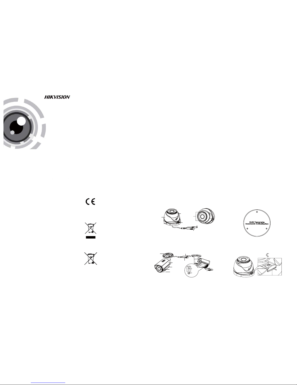
1.2 .1 Over view of Ty pe I Came ra
Enclosure
Trim R ing
Camera
Lock Screw
Video Cable
Power C able
Zoom & F ocus
Fig ure 1-1 O vervi ew of Type I Ca mera
1.2 .2 Over view of Ty pe Came ra
Mounting Base
Sun Shield
Main Body
Lens
IR LED
Video Cable
Power C able
Adjusting Sheet
Focus
Zoom
l Ple ase make s ure tha t the dev ice in th e packag e
is in good condition and all the assembly parts
are i nclud ed.
l Make s ure tha t all the re lated e quipm ent is
power-off during the installation.
l Check the specification of the products for the
installation environment.
l Check whether the power supply is matched
wit h your po wer outp ut to avo id dama ge.
l Ple ase make s ure the w all is str ong eno ugh to
withstand three times the weight of the camera
and the mounting.
l If th e wall is t he ceme nt wall, y ou need t o inser t
exp ansio n screws b efore yo u instal l the cam era.
If the wall is the wooden wall, you can use
sel f-tap ping sc rew to sec ure the c amera.
l If the product does not function properly,
please contact your dealer or the nearest
ser vice ce nter. Do not d isass emble t he came ra
for repair or maintenance by yourself.
2.1 Installation of Type CameraI
l
High performance CMOS sensor and high
resolution bring high-quality image;
l
Low i llumi natio n, 0.01 L ux @ (F1. 2, AGC ON) ,
0 Lux w ith IR;
l
Support IR cut filter with auto switch;
l
OSD m enu, pa ramete rs are con figur able;
l
Support auto white balance, auto gain control,
electronic shutter control and internal
synchronization;
l
Advanced Engineering Design and patent
universal adjustable structure provides
convenient adjustment and high reliability;
SMA RT IR mod e;
l
l
Unit transmission control;
l
Advanced 3-axis design meets different
installation requirements;
l
Ingress protection: IP66.
1.Dr ill the s crew ho les and t he cable h ole on th e
ceiling according to the supplied drill template.
2 Loosen the lock screw and release the clip
.
plate to disassemble the camera from the
mounting base.
Clip Plate
3.Fix the mounting base to the ceiling.
Figure 2-2 Release The Lock Screw
Steps:
UD.6L0201D1282A01
www.hikvision.com
Page 2
Fig ure 3-3 M anual o f WB
Fig ure 3-4 S mart Mo de of DAY&N IGHT
Fig ure 3-5 V ideo Set tings
3.3 DAY & NIGHT
3.4 Video Setting
Mov e the curs or to the V IDEO SE TTING , and pre ss
the m enu but ton to ent er the vi deo conf igura tion
int erface . As show n in Figu re 3-5.
3.5 FUNCTION
Move the cursor to DAY & NIGHT, and select
COLOR B/W SMART, , or as th e DAY & NIGHT m ode.
3.6 R eset
Res et all the s ettin gs to the d efault .
3.7 S ave & Exit
Mov e the curs or to , and p ress OK toSAVE & R ESET
save t he sett ings an d exit th e menu.
3 Menu Operation
A coaxial camera controller (purchase separately)
is required to select the menu and adjust the
camera param eters.
3.1 AE
Move the cursor to AE, and you can adjust the
ima ge brig htnes s by the , ,BRIGHTNESS AE MODE
AGC SENS-UP, and in thi s menu.
As shown in Figure 3-2.
Figure 3-1 Main Menu
Figure 3-2 AE
4.Route the cables to the cable hole and connect
the corresponding cables.
5.Secure the camera to the mounting base by
tightening the lock screw.
6.Adjust the camera according to the figure below
to get a n optim um angl e.
0 ~360
0 ~75
0 ~360
Figure 2-3 3-axis Adjustment
7.Use the screwdriver to adjust the ZOOM screw
and t he FOCU S screw un til you g et the opt imum
image.
Fig ure 2-4 Zo om and Fo cus Adj ustme nt
2.2 Installation of Type CameraII
Steps:
1. Drill the screws holes on the ceiling according
to the supplied drill template.
Figure 2-5 The Drill Template
2.Route the corresponding cables.
3.Secure the camera to the ceiling with the selftapping Screws
.
Figure 2-6 Secure the Camera to the Ceiling
4.Connect the corresponding cables.
5. Lo osen th e T screw, R sc rew and P sc rew
successively and adjust the camera according to
the f igure b elow to ge t an opti mum ang le. Tig hten
the s crew aft er comp letin g the adj ustme nt.
R Screw
T Screw
P Screw
6.Adjust the Zoom Screw and Focus Screw till you
get the optimum surveillance angle.
Figure 2-7 3-axis Adjustment
Focus
Zoom
Figure 2-8 Zoom and Focus Adjustment
Setup
AE
WB
DAY
&NIGHT
VIDEO
SETTING
FUNCTION RESET
SAVE
&EXIT
BRIGHTNESS
AEMODE
AGC
SENSEUP
AUTO
MANUAL
COLOR
B/W
CONTRAST
SHARPNESS
COLOR
GAIN
3DNR
MIRROR
DETECTION
MASKING
ZOOMIN
LANGUAGE
SMART
BRIGHTNESS: Set t he brig htness v alue fr om
1 to 10 t o darken o r brigh ten the im age.
: Set A E mode as G LOBLE AE , andAE MODE
D-WDR.
AGC HIGH MIDDLE LOW: , , and ca n be set for t he
AGC level. Select OFF to disable the AGC.
: Set t he SENS E UP value a s 0, 2, 4, 8, 1 0,SENSE UP
12, 1 4 and 16.
3.2 WB
Mov e the curs or to WB, a nd you can s et Whit e
Balance mode as and in this menuAUTO MANUAL .
AUTO: whit e balan ce is bei ng adju sted
automatically.
: Set t he val ueMANUAL R GAIN/B GAIN
fro m 1 to 10. As sh own in Fi gure 3- 3.
COLOR: The i mage is c olored i n day mod e all the
time.
: The im age is bl ack & whi te all th e time, a ndB/W
the IR LED turns on in the low-light conditions.
: Select to turn on/off the INFRARED_LAMPSMART
and t o set the S mart IR l evel fro m 0 to 5.
As sh own in Fi gure 3- 4.
SAMRT
1. INFRARED_LAMP OFF
2. SMART IR 0-|--5
3. RETURN 8
Set t he scre en ratio a s 4:3/1 6:9.SCREEN RATIO:
CONTRAST: Set th e CONTR AST val ue from 1 to 1 0.
: Set t he edge a nd detai l sharp nessSHARPNESS
val ue from 1 to 1 0.
COLOR GAIN: Set t he color g ain fro m 1 to 10.
: Set t he 3D NR le vel as , ,3D NR High Middle
and . Select to disable the 3D NR.Low OFF
: Set t he mirro r mode as , ,MIRROR OFF H
, or .VHV
You can s et , , an dDETECTION MASKING ZOOM IN
of th e camera i n this me nu.LANGUAGE
FUNCTION
1. DETECTION
8
2. MASKING 8
3. ZOOM IN 50-|--100
4. LANGUAGE ENGLISH
5. RETURN
8
Fig ure 3-6 F uncti on
DETECTION: Set the motion sensitivity as
, , or . Select an AREA toWEAK LOW MIDDLE HIGH
ent er the mot ion det ectio n AREA me nu. As sh own
in Figure 3-7.
: Set the status as / . Select a color forAREA OFF ON
are a border. Mo ve the jo ystick u p/dow n and rig ht
/le ft to set th e horiz on/ve rtical s ize and p ositi on.
As sh own in Fi gure 3- 8.
MASKING: Select a masking back ground color.
Select an AREA to enter the masking AREA menu.
As sh own in fi gure 3- 9.
: Set t he statu s as / . Move t he joys tickAREA OFF ON
up/down and right/left to set the horizon/vertical
size and position.
As shown in Figure 3-10.
ZOOM IN: The ZOOM IN value can be adjusted from
50 to 100.
LANGUAGE:Chinese and English are selectable.
DETECTION
1. SENSITIVITY HIGH
2. AREA NO.0
8
3. AREA NO.1 8
4. AREA NO.2 8
5. AREA NO.3 8
6. RETURN 8
AREA
1. STATUS OFF
2. COLOR
WHITE
3. HORIZON SIZE 0
4. VERTICAL SIZE 0
5. HORIZON MOVE 0
6. VERTICAL MOVE 0
7. RETURN
8
Figure 3-7 Detection
Figure 3-8 Detection Area
MASKING
1. COLOR WHITE
2. AREA NO.0
8
3. AREA NO.1 8
4. AREA NO.2 8
5. AREA NO.3 8
6. AREA NO. 8
7. AREA NO.5 8
8. AREA NO.6 8
9. AREA NO.7 8
10.RETURN 8
AREA
1. STATUS OFF
2. HORIZON SIZE 0
3. VERTICAL SIZE 0
4. HORIZON MOVE 0
5. VERTICAL MOVE 0
6. RETURN
8
Fig ure 3-9 M arskin g Area
Figure 3-10 Masking
AE
1. BRIGHTNESS 1-|--10
2. AE MODE DWDR
3. AGC OFF
4. SENSE UP 0-|---16
5. RETURN 8
VIDEO SETTING
1. SCREEN RATIO 4:3
2. CONTRAST 1-|--10
2. SHARPNESS
8
3. COLOR GAIN 1-|--10
4. 3D NR OFF
5. MIRROR OFF
6. RETURN
8
MANUAL
1. R GIAN 1-|--10
2. B GAIN 1-|--10
3. RETURN 8
 Loading...