

HIKVISION DS-2CE5582PN, DS-2CE55C2P-IR, DS-2CE5582P, DS-2CE5582P-IR, DS-2CE5582PN-IR User Manual
...Page 1
Dome Camera
User Manua l
www. hikvi sion. com
Tha nk you for p urcha sing ou r produ ct. If th ere
are a ny quest ions, o r reque sts, ple ase do no t
hes itate to c ontact t he deal er.
Thi s manua l appli es to
Type
Mod el
I
DS- 2CE55 82P(N ), DS-2 CE55C 2P(N)
DS- 2CE55 82P(N )-IRP, DS- 2CE55 C2P(N )-IRP
DS- 2CE55 82P(N )-IR, DS-2C E55C2 P(N)- IR
DS- 2CE56 82P(N )-IT3 , DS-2C E56C2 P(N)- IT3
II
III
IV
DS- 2CE55 82P(N )-VFI R3
Thi s manua l may cont ain sev eral tec hnica l
inc orrect p laces o r print ing err ors, and t he
con tent is su bject t o chang e witho ut noti ce.
The u pdate s will be a dded to th e new ver sion of
thi s manua l. We will r eadil y improv e or upda te
the p roduc ts or proc edure s descr ibed in t he
man ual.
DIS CLAIM ER STATEMENT
Und erwri ters Lab orato ries In c. (”UL”) has n ot
test ed the pe rform ance or re liabi lity of t he
sec urity o r signa ling as pects o f this pr oduct .
Reg ulatory I nformat ion
FCC I nformatio n
FCC c ompli ance: T his equ ipment h as been
test ed and fo und to com ply wit h the lim its for a
dig ital de vice, p ursuan t to part 1 5 of the FC C
Rul es. The se limi ts are de signe d to provi de
rea sonab le prote ction a gainst h armfu l
int erfere nce whe n the equ ipment i s opera ted in
a com mercia l envir onment . This eq uipme nt
gen erates , uses, a nd can rad iate rad io
fre quenc y energy a nd, if no t insta lled an d used
in ac cordan ce with t he inst ructi on manu al, may
cau se harm ful inte rferen ce to rad io
com munic ations . Opera tion of t his equ ipmen t in
a res identi al area i s likely t o cause h armfu l
int erfere nce in wh ich case t he user w ill be
req uired to c orrec t the inte rferen ce at his o wn
exp ense.
UL Ce rtifi catio n does no t
per forman ce or rel iabil ity of th e
sig nalin g aspec ts of thi s produ ct UL MAK ES NO
REP RESEN TATION S, WARRA NTIES O R
CER TIFIC ATIO NS WHATSO EVER RE GARDI NG
THE P ERFOR MANCE O R RELIA BILIT Y OF ANY
SEC URITY O R SIGNA LING RE LATED FUN CTION S
OF TH IS PROD UCT.
cove r the
sec urity o r
010 00010 30115
FCC C ondit ions
Thi s devic e compl ies wit h part 15 o f the FCC
Rul es. Ope ration i s subje ct to the f ollow ing two
con ditio ns:
1. Th is devi ce may not c ause ha rmful
int erfere nce.
2. Th is devi ce must a ccept an y inter ferenc e
rec eived, i nclud ing int erfere nce tha t may
cau se unde sired op erati on.
EU Co nform ity Statement
Thi s produ ct and - if a pplica ble -
the s uppli ed acce ssori es too are
mar ked with " CE" and c omply
upo n the p urc has e of eq uiva len t new e qui pmen t,
or di spo se of i t at de sig nat ed col lec tio n poi nts .
For m ore i nfo rma tion s ee:
www. recycl ethis .info.
200 6/66/ EC (batt ery dir ective ):
Thi s produ ct conta ins a batt ery
tha t canno t be disp osed of a s
uns orted m unici pal wast e in the
Eur opean U nion.
See t he prod uct doc umenta tion for s pecif ic
batt ery inf ormati on. The b atter y is marke d with
thi s symbo l, whic h may incl ude let tering t o
ind icate ca dmium ( Cd), le ad (Pb) , or merc ury (Hg ).
For p roper re cycli ng, retu rn the ba ttery t o your
sup plier o r to a desi gnated c ollec tion po int. Fo r
mor e inform ation s ee:
www. recycl ethis .info.
Thi s serie s of came ra adopt s new gen eratio n
sen sor wit h high se nsiti vity an d advan ced circ uit
des ign tec hnolo gy. It fe ature s high res oluti on
low i mage di storti on and lo w noise etc . whic h
make s it suit able for s urvei llanc e system a nd
ima ge proce ssing s ystem.
●Hig h-per forman ce sens or and h igh reso lutio n
bri ng high -qual ity ima ge
●IR LE D enabl es day night su rveil lance
●Day /night a uto swi tch
●ATW bri ngs hig h color r endit ion
●Aut o elect ronic sh utter c ontrol t o adapt t o the
dif ferent s urvei llanc e enviro nment s
●Aut o gain con trol, a daptiv e brigh tness
●Hig h SNR bri ngs hig h-qua lity im age
●Ing ress pro tecti on: IP6 6
Type Ⅰ ca mera doe sn’t su pport d ay nig ht auto
swi tch and I P .
DS- 2CE55 82P N I RP and DS - C E55C P N IRP
don ’t supp ort IP6 6.
,
, ,
/
Not es:
/
66
( )- 2 2 ( ) -
1 Introduction
1.1 Prod uct F eatures
1.2 Overview
2 Installation
Bef ore you s tart:
●Ple ase make s ure tha t the dev ice in th e packag e
is in g ood con ditio n and all t he asse mbly pa rts
are i nclud ed.
●Ple ase make s ure tha t all the re lated e quipm ent
is po wer-o ff durin g the ins talla tion.
●Che ck the sp ecifi catio n of the pro ducts f or the
ins tallat ion env ironme nt.
●Che ck whet her the p ower su pply is m atched
wit h your AC o utlet to a void da mage.
●If th e produ ct does n ot func tion pro perly, p lease
con tact you r deale r or the ne arest se rvic e
cen ter. Do not di sasse mble th e camer a for
rep air or ma intena nce by yo urself .
●Ple ase make s ure tha t the wall o r the cei ling is
stro ng enou gh to wit hstan d 3 times t he weigh t
of th e camera .
UD.6 L0201 D0172 A01
the refore w ith the a pplica ble har moniz ed
Eur opean st andar ds liste d under t he Low Vol tage
Dir ective 2 006/9 5/EC, t he EMC Di recti ve 2004/
108 /EC.
UL ha s only te sted for f ire, sho ck or cas ualty
haz ards as ou tline d in Ul’s St andard (s) for S afety,
UL6 0950- 1.
200 2/96/ EC (WEE E direct ive):
Pro ducts m arked wi th this sy mbol
can not be di spose d of as uns orted
mun ici pal w ast e in th e Euro pea n
Uni on. F or pr ope r recy cli ng, r etu rn
thi s pro duc t to yo ur lo cal su ppl ier
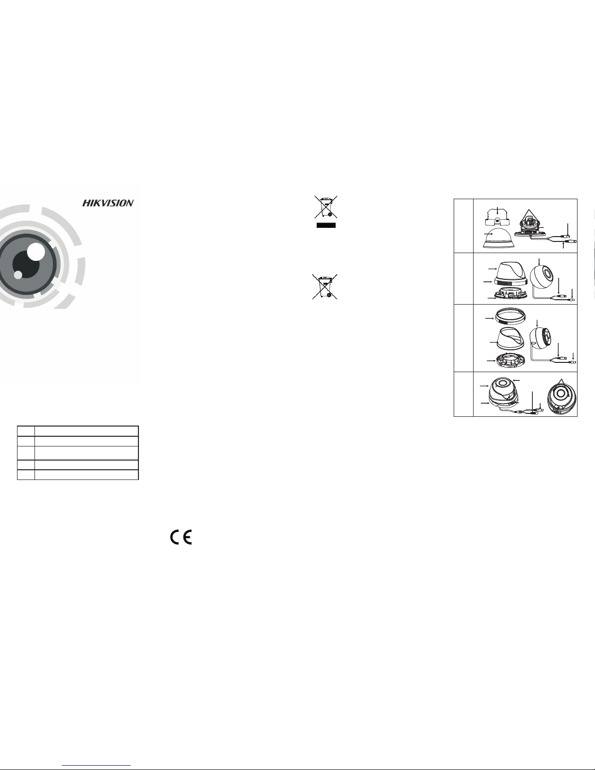
Power
Cable
Power
Cable
Power Cabl e
Zoom & Focu s
Video Ca ble
Video
Cable
Power Cabl e
Mountin g
Base
Lock
Screw
Enclos ure
Camera
TYPE
II
Enclos ure
Trim Ring
Mountin g
Base
Video
Cable
Enclos ure
Trim Ring
Mountin g
Base
Video
Cable
Camera
TYP E
III
Camera
Adjusta ble Screw
Black Li ner
Lower
Dome
TYP E
IV
TYP E
I
Camera
Page 2

1.H old the m ounti ng base , and rota te the lo wer
dom e counte rcloc kwise t o disas sembl e the
low er dome a nd the bl ack lin er.
2.D rill th e screw ho les and t he cabl e hole the
cei ling ac cordin g to the su pplie d drill t empla te.
on
83.5
2-∅4.5
Ste ps:
Fig ure 2-1 T he Disa ssemb ling
2.1 Ceiling Mounting for Type I
Camera
3.Ro ute the ca bles to t he cabl e hole an d
the c orresp ondin g power c able an d video c able.
4.Se cure th e mounti ng base t o the cei ling wi th
the s elf t appin g screws .
con nect
-
6.Fi t the bla ck line r back to t he camer a.
7.In stall th e lower d ome bac k to the ca mera and
rota te it clo ckwis e to get it se cured .
Fig ure 2-2 T he Secu ring & 3- axis Adj ustme nt
5.Ad just th e Lens
1).L oosen t he tilt ing loc k screws b eside s the
len s.
2).A djust t he came ra from th e pan ang le
( de grees ); tilt a ngle (0 ~90 deg rees) ,
and r otate th e lens( 0~355 d egree s) to get th e
opt imum an gle.
3).T ighte n the tilt ing loc k screw s.
0~3 55
108
Screw Hole
∅86
108
∅72
Ste ps:
1.Dr ill the s crew ho les and th e cable h ole
acc ording t o the dri ll temp late.
Fig ure 2-5 D rill Temp late of Typ e Ⅲ Camer a
2.Se cure th e mounti ng base t o the cei ling wi th
the s crews.
Fig ure 2-6 S ecure th e Mount ing Bas e
3.Ro ute the ca bles to t he cabl e hole an d
the c orresp ondin g power c able an d
vid eo cabl e.
4.Se cure th e camera t o the mou nting b ase.
5.In stall th e enclo sure an d the tri m ring to
cam era.
con nect
Fig ure 2-7 S ecure th e Compo nents
Camera
Fig ure 2-4 D rill Temp late of Typ e Ⅱ Camer a
110
Hole
Ceiling Mounting
Hole
110
∅102
∅5
∅20
83.5
2.2 Ceiling Mounting for Type II/ III
Screw Hole
Template
3-∅4.5
∅110
45
39
39
22.5
22.5
6.Ad just th e surve illan ce angl e accord ing to th e
fig ure bel ow.
7.Ro tate the t rim rin g clock wise to se cure th e
cam era.
Fig ure 2-1 0 The Loc k Screw
Fig ure 2-8 L ens Adj ustmen t
2.3 Ceiling Mounting for Type IV
Camera
Fig ure 2-9 T he Dril l Temp late
2.Lo osen th e lock sc rew to dis assem ble the
cam era from t he moun ting ba se.
3.Se cure th e mounti ng base t o the cei ling.
Ste ps:
1.Dr ill the s crews ho les and t he cabl e hole on t he
cei ling ac cordin g to the su pplie d drill t empla te.
360°
360°
0-75°
P 0°an -360°
Rotation 0°-360°
Tilt 0°-75°
4.Ro ute the ca bles to t he cabl e hole an d connec t
the c orresp ondin g cable s.
5.Se cure th e camera t o the mou nting b ase by
tig hteni ng the loc k screw.
6.Ad just th e camera a ccord ing to the f igure
bel ow to get an o ptimu m angle .
Fig ure 2-1 1 Lens Ad justme nt
7.U se the sc rewdri ver to ad just the Z OOM scr ew
and t he FOCU S screw un til you g et the
opt imum im age.
Fig ure 2-12 Zo om and Fo cus Adj ustme nt
2.4 Power Sup ply
Fig ure 2-1 3 The Powe r Cable & t he Vide o Cable
Not e:
Ple ase make s ure tha t the powe r adapt er is
com patib le with t he camer a, and th e standa rd
pow er supp ly is 12V D C. Ple ase refe r to the
tec hnica l speci ficati on for mo re infor matio n.
Fig ure 2-3 C omple te the Ins talla tion
 Loading...