

Page 1

Network Camera
Operation Guide
UD.6L0201D0041A01
Page 2

Network Camera·Quick Operation Guide
1
1
Thank you for purchasing our product. If there are any questions,
or requests, please do not hesitate to contact the dealer.
About This Manual:
This manual applies to DS-2CD883F-E(W), DS-2CD855F-E,
DS-2CD854F(WD)-E(W), DS-2CD853F-E(W),
DS-2CD864F(WD)-E(W), DS-2CD863PF(NF)-E(W),
DS-2CD893PFWD(NFWD)-E(W), DS-2CD833F-E(W),
DS-2CD893PF(NF)-E(W) series camera.
This manual may contain several technical incorrect places or
printing errors, and the content is subject to change without notice.
The updates will be added to the new version of this manual. We
will readily improve or update the products or procedures
described in the manual.
DISCLAIMER STATEMENT
“Underwriters Laboratories Inc. (“UL”) has not tested the
performance or reliability of the security or signaling aspects of
this product. UL has only tested for fire, shock or casualty hazards
as outlined in UL’s Standard(s) for Safety, UL60950-1. UL
Certification does not cover the performance or reliability of the
security or signaling aspects of this product. UL MAKES NO
REPRESENTATIONS, WARRANTIES OR CERTIFICATIONS
WHATSOEVER REGARDING THE PERFORMANCE OR RELIABILITY
OF ANY SECURITY OR SIGNALING RELATED FUNCTIONS OF THIS
PRODUCT.
0400031020820
Page 3

Network Camera·Quick Operation Guide
2
2
Regulatory Information
FCC Information
FCC compliance: This equipment has been tested and found to
comply with the limits for a digital device, pursuant to part 15 of
the FCC Rules. These limits are designed to provide reasonable
protection against harmful interference when the equipment is
operated in a commercial environment. This equipment generates,
uses, and can radiate radio frequency energy and, if not installed
and used in accordance with the instruction manual, may cause
harmful interference to radio communications. Operation of this
equipment in a residential area is likely to cause harmful
interference in which case the user will be required to correct the
interference at his own expense.
FCC Conditions
This device complies with part 15 of the FCC Rules. Operation is
subject to the following two conditions:
1. This device may not cause harmful interference.
2. This device must accept any interference received, including
interference that may cause undesired operation
EU Conformity Statement
This product and - if applicable - the supplied
accessories too are marked with "CE" and comply
therefore with the applicable harmonized
European standards listed under the Low Voltage Directive
2006/95/EC, the EMC Directive 2004/108/EC.
Page 4

Network Camera·Quick Operation Guide
3
3
2002/96/EC (WEEE directive): Products marked
with this symbol cannot be disposed of as unsorted
municipal waste in the European Union. For proper
upon the purchase of equivalent new equipment, or dispose of it at
designated collection points. For more information see:
www.recyclethis.info.
symbol, which may include lettering to indicate cadmium (Cd),
lead (Pb), or mercury (Hg). For proper recycling, return the battery
to your supplier or to a designated collection point. For more
information see: www.recyclethis.info.
recycling, return this product to your local supplier
2006/66/EC (battery directive): This product
contains a battery that cannot be disposed of as
unsorted municipal waste in the European Union.
See the product documentation for specific battery
information. The battery is marked with this
Page 5

Network Camera·Quick Operation Guide
4
4
Contents
1 Appearance Description ................................................ 5
1.1 Camera Description ..............................................5
1.2 Camera wiring diagram .........................................8
2 Installation ................................................................... 9
3 Setting the Network Camera over the LAN .................. 13
4 Accessing via WEB browser ......................................... 20
Page 6
Network Camera·Quick Operation Guide
5
5
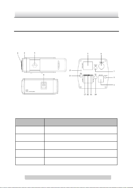
No.
Description
1
Lens mount
2
Back Focus Ring
3
SD card slot
4
Auto-iris interface
5
10M/100M self-adaptive Ethernet interface
1 Appearance Description
1.1 Camera Description
Figure 1-1 Overview
Table 1-1 Description
Page 7

Network Camera·Quick Operation Guide
6
6
6
VIDEO OUT: Video output interface
7
AUDIO OUT: Audio output interface
8
POWER: Power LED indicator
9
Power supply interface
10
MIC IN: Audio input interface
11
D+, D-: RS-485 interface
12
IN, G: Alarm input interface
13
1A, 1B: Alarm output interface
14
Ground
15
RESET: Reset button
Notes:
To reset the default parameters to the camera, you need to
press and hold the RESET button and power on the camera.
After the power on of the camera, you must still press and hold
the Reset button for about 20 seconds.
The type of auto-iris interface is shown as below figure:
Page 8
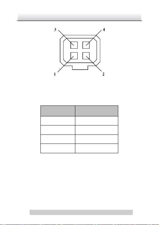
Network Camera·Quick Operation Guide
7
7
DC-driven
1
Damp-
2
Damp+ 3 Drive+ 4 Drive-
Figure 1-2 Auto-iris Interface
Table 1-2 Pins
Power, Video and GND pins are used when the auto-iris is driven by
video; Damp+, Damp-, Drive+ and Drive- pins are used when the
auto-iris is driven by DC.
Page 9
Network Camera·Quick Operation Guide
8
8
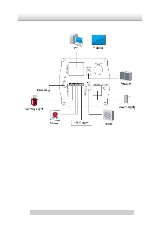
1.2 Camera wiring diagram
Figure 1-3 Wiring Diagram
Page 10

Network Camera·Quick Operation Guide
9
9
2 Installation
Before you start:
Read the following contents carefully before the installation.
Make sure that all the related equipment is power-off during
the installation.
Check whether the power supply is matched with your AC
outlet to avoid damage.
Do not place the camera in extremely hot or damp
environment. To avoid heat accumulation, good ventilation is
required for a proper operating environment.
If the product does not function properly, please contact your
dealer or the nearest service center. Do not disassemble the
camera for repair or maintenance by yourself.
The box camera can be installed to both wall and ceiling. Ceiling
mounting is taken as an example in this section; if you adopt wall
mounting, you can also take the below procedure as a reference.
Steps:
1. Fix the mounting bracket to the ceiling.
Page 11

Network Camera·Quick Operation Guide
10
10
Figure 2-1 Fix Camera Mounting Bracket
Notes:
For cement ceiling mounting, you need to use the
expansion screw to fix the bracket. The mounting hole of
the expansion pipe on the wall should align with the
mounting hole on the bracket.
For wooden ceiling mounting, you can just use the
self-tapping screw to fix the bracket.
The ceiling must be strong enough to withstand more than
5 times the weight of the camera and the bracket.
2. Aim the screw hole on the camera at the bracket and rotate the
camera tightly. Adjust the camera to the desired surveillance
angle and tighten the knob on bracket to secure the camera.
Page 12

Network Camera·Quick Operation Guide
11
11
Figure 2-2 Fix the Camera
3. Mount the camera lens.
Connect the VIDEO OUT interface of the camera to the
debugging monitor. Adjust the lens focus to obtain a perfect
image on the monitor, and finally lock the lens. If required,
loosen the knob on the mounting bracket and adjust the
camera to the desired surveillance angle, and finally tighten
the knob on bracket.
Page 13

Network Camera·Quick Operation Guide
12
12
Figure 2-3 Mount and Adjust Lens
Page 14

Network Camera·Quick Operation Guide
13
13
3 Setting the Network
Camera over the LAN
Purpose:
To view and configure the camera via LAN(Local Area Network),
you need to connect the network camera in the same subnet with
your PC. Then, install the SADP or iVMS-4200 software to search
and change the IP of network camera.
The following figure shows the cable connection of network
camera and PC:
Figure 3-1 Wiring over LAN
Set the IP address of the camera for accessing via LAN.
Steps:
1. To get the IP address, you can choose either of the following
methods:
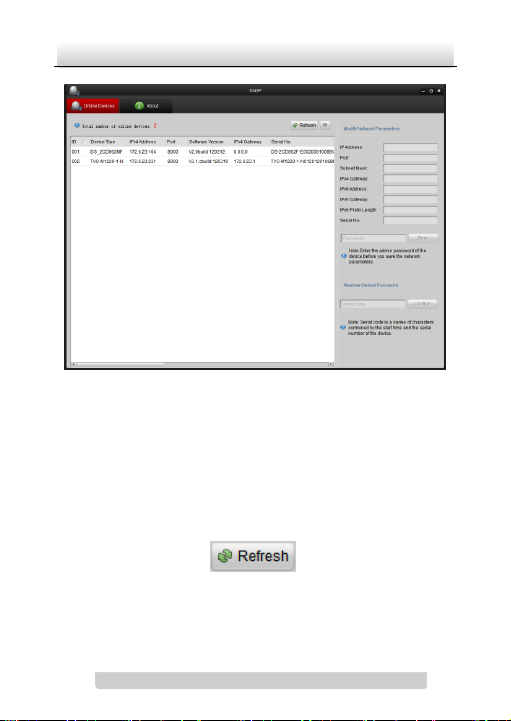
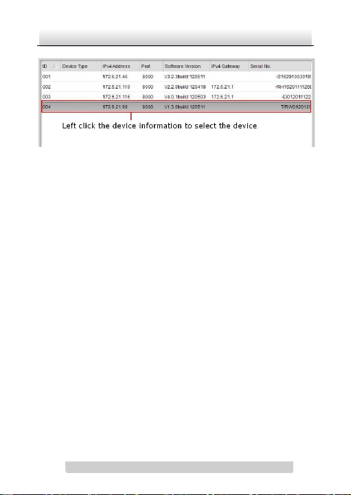
Use SADP, a software tool which can automatically detect
network camera in the LAN and list the device information
like IP address, subnet mask, port number, device serial
number, device version, etc., shown in Figure 3-2.
Page 15

Network Camera·Quick Operation Guide
14
14
Use iVMS-4200 software and to list the online devices.
Please refer to the user manual of client software for
detailed information.
2. Change the IP address and subnet mask to the same subnet as
of your PC.
Refer to the following introductions to set IP address with
SADP software:
Search active devices online
Search online devices automatically:
After launch the SADP software, it automatically searches
the online devices every 15 seconds from the subnet where
your computer locates. It displays the total number and
information of the searched devices in the Online Devices
interface. Device information including the device type, IP
address, port number, gateway, etc. will be displayed.
Page 16
Network Camera·Quick Operation Guide
15
15
Figure 3-2 Searching Online Devices
Note: Device can be searched and displayed in the list in 15
seconds after it goes online; it will be removed from the list
in 45 seconds after it goes offline.
Search online devices manually:
You can also click to refresh the online
device list manually. The newly searched devices will be
added to the list.
Page 17

Network Camera·Quick Operation Guide
16
16
Note: You can click or on each column heading
to order the information; you can click to show the
device table and hide the network parameter panel on the
right side, or click to show the network parameter
panel.
Modify device information
Steps:
1). Select the device to be modified in the device list as shown
in Figure 3-3. The network parameters of the device will be
displayed in the Modify Network Parameters panel on the
right side as shown in Figure 3-4.
2). Edit the modifiable network parameters, e.g. IP address
and port number.
3). Enter the password of the admin account of the device in
the Password field and click to save the
changes.
Page 18
Network Camera·Quick Operation Guide
17
17
Figure 3-3 Select a device
Page 19

Network Camera·Quick Operation Guide
18
18
Figure 3-4 Modify Network Parameters
3. Enter the IP address of network camera in the address field of
the web browser to view the live video.
Page 20

Network Camera·Quick Operation Guide
19
19
Note:
The default value of the IP address is “192.0.0.64”. The default
user name is “admin”, and password is “12345”.
For accessing the network camera from different subnets,
please set the gateway for the network camera after you log in.
Page 21

Network Camera·Quick Operation Guide
20
20
4 Accessing via WEB browser
System Requirement:
Operating System: Microsoft Windows XP SP1 and above version /
Vista / Win7 / Server 2003 / Server 2008 32bits
CPU: Intel Pentium IV 3.0 GHz or higher
RAM: 1G or higher
Display: 1024×768 resolution or higher
Web Browser: Internet Explorer 6.0 and above version, Apple
Safari 5.02 and above version, Mozilla Firefox 3.5 and above
version and Google Chrome8 and above version
Before you start:
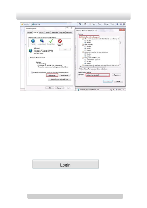
Check the security level of the web browser and change it to Low.
On the IE browser menu bar, navigate to Tools > Internet
options > Security > Custom level to customize the level to
LOW.
Page 22
Network Camera·Quick Operation Guide
21
21
Figure 4-1 Adjust the Security Level
Steps:
1. Open the web browser.
2. In the browser address bar, input the IP address of the network
camera, e.g., 192.0.0.64 and press the Enter key to enter the
login interface.
3. Input the user name and password.
4. Click .
Page 23

Network Camera·Quick Operation Guide
22
22
Figure 4-2 Login Interface
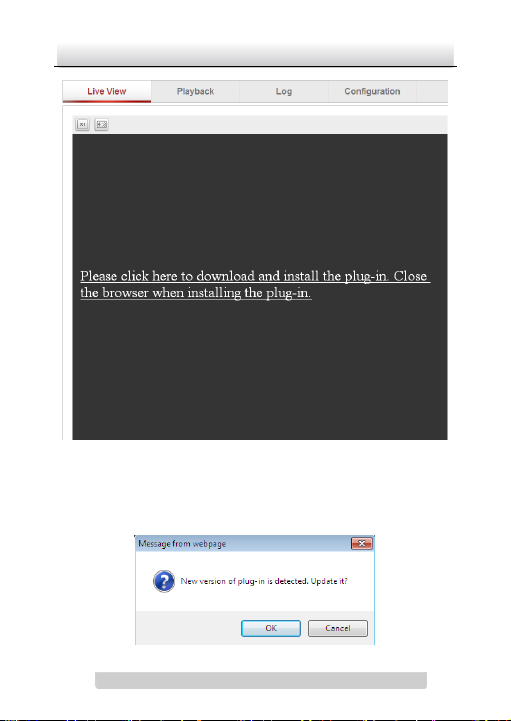
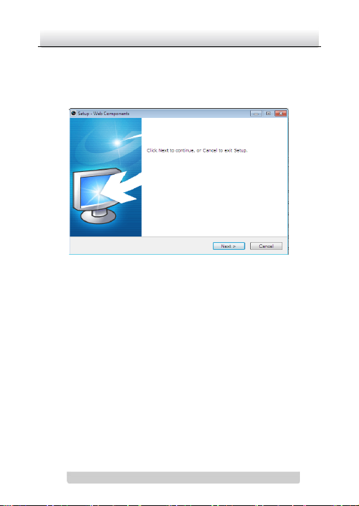
5. Install the plug-in before viewing the live video and managing
the camera. Please follow the installation prompts to install the
plug-in.
Note: You may have to close the web browser to finish the
installation of the plug-in.
Page 24
Network Camera·Quick Operation Guide
23
23
Figure 4-3 Download Plug-in
Page 25
Network Camera·Quick Operation Guide
24
24
Figure 4-4 Download Plug-in
Figure 4-5 Install Plug-in
Page 26

Network Camera·Quick Operation Guide
25
25
Figure 4-6 Install Plug-in
6. Reopen the web browser after the installation of the plug-in
and repeat the above steps 2-4 to login.
Note: For detailed instructions of further configuration, please
refer to the user manual of network camera.
Page 27

Network Camera·Quick Operation Guide
26
26
 Loading...