


Network Camera
V4.0.1
Quick Operation Guide

Network Camera·Quick Operation Guide
1
1
Thank you for purchasing our product. If there are any questions,
or requests, please do not hesitate to contact the dealer. This
manual applies to DS-2CD8253F-EI(Z), DS-2CD8233F-EI(Z),
DS-2CD8264FWD-EI(Z), DS-2CD8264F-E, DS-2CD8254F-EI,
DS-2CD8254FWD-E, DS-2CD8283F-EI, DS-2CD8255F-EI
cameras.
This manual may contain several technical incorrect places or
printing errors, and the content is subject to change without notice.
The updates will be added to the new version of this manual. We
will readily improve or update the products or procedures
described in the manual.
DISCLAIMER STATEMENT
“Underwriters Laboratories Inc. (“UL”) has not tested the
performance or reliability of the security or signaling aspects of
this product. UL has only tested for fire, shock or casualty hazards
as outlined in UL’s Standard(s) for Safety, UL60950-1. UL
Certification does not cover the performance or reliability of the
security or signaling aspects of this product. UL MAKES NO
REPRESENTATIONS, WARRANTIES OR CERTIFICATIONS
WHATSOEVER REGARDING THE PERFORMANCE OR RELIABILITY
OF ANY SECURITY OR SIGNALING RELATED FUNCTIONS OF THIS
PRODUCT.
Network Camera·Quick Operation Guide
2
2
1 Physical Description of
Camera
1.1 Camera Description
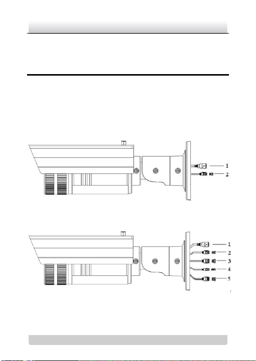
Note: Two types of interfaces of cameras as shown in Figure 1-1
and Figure 1-2. Please choose the right figure according to the
appearance of your camera.
Figure 1-1 Overview
Figure 1-2 Overview
Network Camera·Quick Operation Guide
3
3
No.
Description
1
10M/100M self-adaptive Ethernet interface
2
Power supply interface
3
IN, G: Alarm input interface
1A, 1B: Alarm output interface
4
D+, D-: RS-485 interface
5
AUDIO IN, G: Audio input interface
AUDIO OUT, G: Audio output interface
Table 1-1 Physical Description
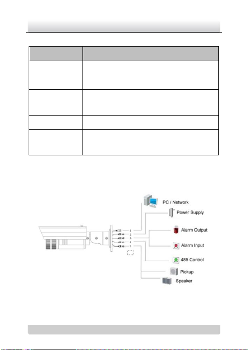
1.2 Camera Wiring Diagram
Figure 1-3 Wiring Diagram

Network Camera·Quick Operation Guide
4
4
2 Installation
Note:
Verify the package contents are correct by checking the items
against the packing list.
Read the following contents carefully before the installation.
Make sure that all the related equipment is power-off during
the installation.
Check whether the power supply is matched with your AC
outlet to avoid any damage.
Do not place the camera in extremely hot or damp
environment. To avoid heat accumulation, good ventilation is
required for a proper operating environment.
If the product does not function properly, please contact your
dealer or the nearest service center. Do not disassemble the
camera for repair or maintenance by yourself.
The bullet camera can be installed to both wall and ceiling. This
quick guide takes wall mounting steps as an example.
Steps:
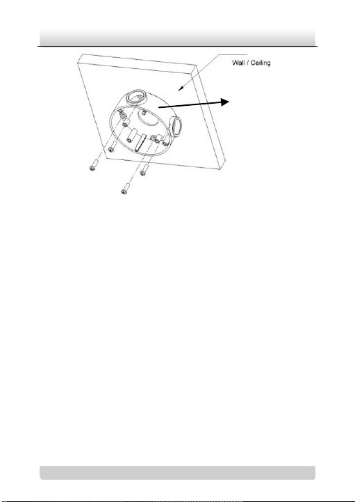
1. Fix the mounting base to the wall. The mounting base can also
be used to keep the cables.
Network Camera·Quick Operation Guide
5
5
Mounting base
Figure 2-1 Fix the Mounting Base
Note:
Please apply water-proof measures between the ceiling
surface and mounting base and around the cables.
For cement wall mounting, you need to use the expansion
screw to fix the mounting base. The mounting hole of the
expansion pipe on the wall should align with the mounting
hole on the mounting base.
For wooden wall mounting, you can just use the
self-tapping screw to fix the mounting base.
The wall must be strong enough to withstand more than 3
times of the weight of the camera and the bracket.
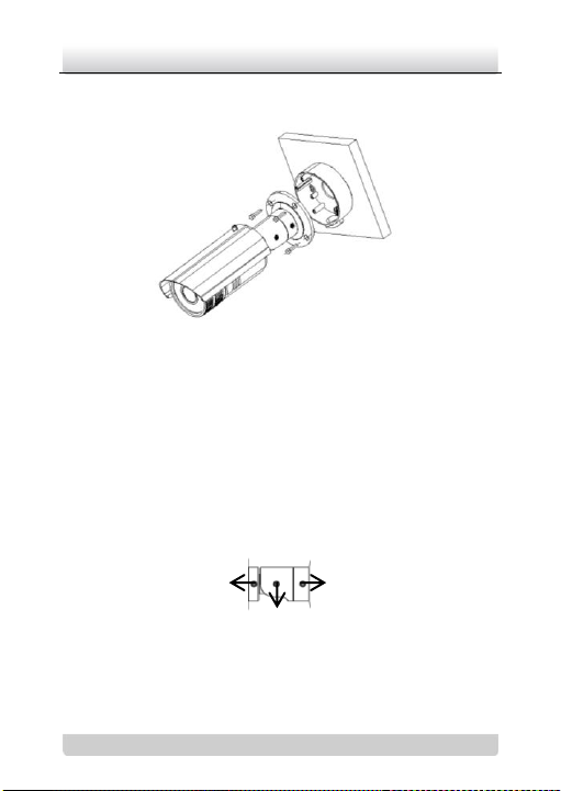
2. Fix the mounting bracket with the camera to the mounting
base.
Network Camera·Quick Operation Guide
6
6
Rotation screw
Panning screw
Tilting screw
Note: The “bottom” mark on the mounting base should align with
the “bottom” mark on the mounting bracket.
Figure 2-2 Fix the Camera
3. View the image of the camera over the network.
4. Loosen the screws on the bracket slightly.
Note: Please loosen the screws slightly until you can adjust the
camera and do not remove the screws from the bracket.
5. Adjust the camera to the desired surveillance angle and then
tighten the screws on bracket to fix the camera.
Figure 2-3 Adjust Monitoring Angle

Network Camera·Quick Operation Guide
7
7
Front
cover
Adjust the
lens
6. Loosen the lock screw on the sun shield and move the sun
shield until you can remove it. Remove the sun shield.
Figure 2-4 Remove the Sun Shield
7. Rotate to remove the front cover from camera and adjust the
lens to get a clear image.
Figure 2-5 Adjust the Lens

Network Camera·Quick Operation Guide
8
8
8. Fix the lens; reinstall the front cover and the sun shield to
finish the installation.
Note: Reinstall the front cover until aligning the mark on the front
cover with the mark on the camera.
Figure 2-6 Reinstall the Camera

Network Camera·Quick Operation Guide
9
9
3 Setting the Network
Camera over the LAN
Purpose:
To view and configure the camera via LAN(Local Area Network),
you need to connect the network camera in the same subnet with
your PC. Then, install the SADP or iVMS-4200 software to search
and change the IP of network camera.
The following figure shows the cable connection of network
camera and PC:
Figure 3-1 Wiring over LAN
Set the IP address of the camera for accessing via LAN.
Steps:
1. To get the IP address, you can choose either of the following
methods:
Use SADP, a software tool which can automatically detect
network camera in the LAN and list the device information

Network Camera·Quick Operation Guide
10
10
like IP address, subnet mask, port number, device serial
number, device version, etc., shown in Figure 3-2.
Use iVMS-4200 software and to list the online devices.
Please refer to the user manual of client software for
detailed information.
2. Change the IP address and subnet mask to the same subnet as
of your PC.
Refer to the following introductions to set IP address with
SADP software:
Search active devices online
Search online devices automatically:
After launch the SADP software, it automatically searches
the online devices every 15 seconds from the subnet where
your computer locates. It displays the total number and
information of the searched devices in the Online Devices
interface. Device information including the device type, IP
address, port number, gateway, etc. will be displayed.

Network Camera·Quick Operation Guide
11
11
Figure 3-2 Searching Online Devices
Note: Device can be searched and displayed in the list in 15
seconds after it goes online; it will be removed from the list
in 45 seconds after it goes offline.
Search online devices manually:
You can also click to refresh the online
device list manually. The newly searched devices will be
added to the list.

Network Camera·Quick Operation Guide
12
12
Note: You can click or on each column heading
to order the information; you can click to show the
device table and hide the network parameter panel on the
right side, or click to show the network parameter
panel.
Modify device information
Steps:
1). Select the device to be modified in the device list as shown
in Figure 3-3. The network parameters of the device will be
displayed in the Modify Network Parameters panel on the
right side as shown in Figure 3-4.
2). Edit the modifiable network parameters, e.g. IP address
and port number.
3). Enter the password of the admin account of the device in
the Password field and click to save the
changes.

Network Camera·Quick Operation Guide
13
13
Figure 3-3 Select a device

Network Camera·Quick Operation Guide
14
14
Figure 3-4 Modify Network Parameters
3. Enter the IP address of network camera in the address field of
the web browser to view the live video.

Network Camera·Quick Operation Guide
15
15
Note:
The default value of the IP address is “192.0.0.64”. The default
user name is “admin”, and password is “12345”.
For accessing the network camera from different subnets,
please set the gateway for the network camera after you log in.

Network Camera·Quick Operation Guide
16
16
4 Accessing via WEB browser
System Requirement:
Operating System: Microsoft Windows XP SP1 and above version /
Vista / Win7 / Server 2003 / Server 2008 32bits
CPU: Intel Pentium IV 3.0 GHz or higher
RAM: 1G or higher
Display: 1024×768 resolution or higher
Web Browser: Internet Explorer 6.0 and above version, Apple
Safari 5.02 and above version, Mozilla Firefox 3.5 and above
version and Google Chrome8 and above version
Before you start:
Check the security level of the web browser and change it to Low.
On the IE browser menu bar, navigate to Tools > Internet
options > Security > Custom level to customize the level to
LOW.

Network Camera·Quick Operation Guide
17
17
Figure 4-1 Adjust the Security Level
Steps:
1. Open the web browser.
2. In the browser address bar, input the IP address of the network
camera, e.g., 192.0.0.64 and press the Enter key to enter the
login interface.
3. Input the user name and password.
4. Click .

Network Camera·Quick Operation Guide
18
18
Figure 4-2 Login Interface
5. Install the plug-in before viewing the live video and managing
the camera. Please follow the installation prompts to install the
plug-in.
Note: You may have to close the web browser to finish the
installation of the plug-in.

Network Camera·Quick Operation Guide
19
19
Figure 4-3 Download Plug-in

Network Camera·Quick Operation Guide
20
20
Figure 4-4 Download Plug-in
Figure 4-5 Install Plug-in

Network Camera·Quick Operation Guide
21
21
Figure 4-6 Install Plug-in
6. Reopen the web browser after the installation of the plug-in
and repeat the above steps 2-4 to login.
Note: For detailed instructions of further configuration, please
refer to the user manual of network camera.

Network Camera·Quick Operation Guide
22
22
 Loading...