

Page 1

Network Camera
Installation Manual
V5.1.0
UD.6L0201A1219A01
Page 2
Installation Manual of Network Camera
1
Model
Box
Camera
Type I
DS-2CD883F-E(W), DS-2CD855F-E, DS-2CD854F(WD)-E(W),
DS-2CD853F-E(W), DS-2CD864F(WD)-E(W), DS-2CD863PF(NF)-E(W),
DS-2CD893PFWD(NFWD)-E(W), DS-2CD833F-E(W),
DS-2CD893PF(NF)-E(W)
Type II
DS-2CD4012F-(A)(P)(W)(SDI)(FC),
DS-2CD4012FWD-(A)(P)(W)(SDI)(FC),
DS-2CD4024F-(A)(P)(W)(SDI)(FC),
DS-2CD4026FWD-(A)(P)(W),
DS-2CD4032FWD-(A)(P)(W)(SDI)(FC)
Dome
Camera
Type I
DS-2CD733F-E(I)(Z), DS-2CD793PF(NF)-E(I)(Z),
DS-2CD793PFWD(NFWD)-E(I)(Z), DS-2CD763PF(NF)-E(I)(Z),
DS-2CD764FWD-E(I)(Z), DS-2CD764F-E(I)(Z), DS-2CD753F-E(I)(Z),
DS-2CD754F-E(I)(Z), DS-2CD754FWD-E(I)(Z)(B), DS-2CD783F-E(I)(Z),
DS-2CD755F-E(I)(Z)
Type II
DS-2CD7164-E, DS-2CD7153-E, DS-2CD7133-E
Type III
DS-2CD7353F-E (I) (S), DS-2CD7393PF/NF-E (I) (S),
DS-2CD7393PF/NFWD-E (I) (S)
Type IV
DS-2CD7233F-E(I)Z(H)(S), DS-2CD7253F-E(I)Z(H)(S),
DS-CD7254F-E(I)Z(H)(S), DS-CD7254FWD- E(I)Z(H)(S), DS-2CD7255FE(I)Z(H)(S), DS-2CD7283F-E(I)Z(H)(S), DS-2CD7293PFWD(NFWD)E(I)Z(H)(S), DS-2CD7263NF(PF)- E(I)Z(H)(S), DS-2CD 7264FWDE(I)Z(H)(S),DS-2CD7293PF(NF)- E(I)Z(H)(S)
Type V
DS-2CD2112-(I), DS-2CD2132-(I)
Type VI
DS-2CD2712F-I(S), DS-2CD2732F-I(S)
Type VII
DS-2CD4112F-(I)(Z), DS-2CD4124F-(I)(Z)
DS-2CD4132F-(I)(Z), DS-2CD4112FWD-(I)(Z), DS-2CD4132FWD-(I)(Z)
Type
VIII
DS-2CD4312F-(I)(Z)(H)(S), DS-2CD4312FWD-(I)(Z)(H)(S),
DS-2CD4324F-(I)(Z)(H)(S), DS-2CD4332FWD-(I)(Z)(H)(S)
Type IX
DS- 2CD2512F-(I)(W)(S), DS- 2CD2532F-(I)(W)(S)
Bullet
Camera
Type I
DS-2CD833-EI3, DS-2CD864-EI(3)(5), DS-2CD855-EI(3)(5)
Type II
DS-2CD8253F- E(I)(Z)(S), DS-2CD8233F-E(I)(Z)(S),
DS-2CD8264FWD-E(I)(Z)(S),DS-2CD8264F-E(I)(Z)(S), DS-2CD8254FE(I)(Z)(S), DS-2CD8254FWD- E(I)(Z)(S), DS-2CD8283F- E(I)(Z)(S),
DS-2CD8255F- E(I)(Z)(S)
Type III
DS-2CD2012-I, DS-2CD2032-I
Thank you for purchasing our product. If there are any questions, or requests, please do not hesitate
to contact the dealer.
There is variety of structures of network cameras in our company. Installing instructions of all these
cameras are listed in this manual. Find the model of your camera in the following list.
Page 3
Installation Manual of Network Camera
2
Type IV
DS-2CD2212-I, DS-2CD2232-I
Type V
DS-2CD2612F-I(S), DS-2CD2632F-I(S)
Type VI
DS-2CD4212F-(I)(Z)(H)(S), DS-2CD4212FWD-(I)(Z)(H)(S)
DS-2CD4224F-(I)(Z)(H)(S), DS-2CD4232FWD-(I)(Z)(H)(S)
Type VII
DS-2CD6412FWD-10, DS-2CD6412FWD-20
Turret Camera
DS-2CD2312-I5, DS-2CD2332-I5
Cube
Camera
Type I
DS-2CD8153F-E(I)(W), DS-2CD8133F-E(I)(W)
Type II
DS-2CD8464F-E(I)(W), DS-2CD8433F-E(I)(W)
Type III
DS-2CD2412F-I(W), DS-2CD2432F-I(W)
This manual may contain several technical incorrect places or printing errors, and the content is
subject to change without notice. The updates will be added to the new version of this manual. We
will readily improve or update the products or procedures described in the manual.
DISCLAIMER STATEMENT
“Underwriters Laboratories Inc. (“UL”) has not tested the performance or reliability of the security
or signaling aspects of this product. UL has only tested for fire, shock or casualty hazards as outlined
in UL’s Standard(s) for Safety, UL60950-1. UL Certification does not cover the performance or
reliability of the security or signaling aspects of this product. UL MAKES NO
REPRESENTATIONS, WARRANTIES OR CERTIFICATIONS WHATSOEVER REGARDING
THE PERFORMANCE OR RELIABILITY OF ANY SECURITY OR SIGNALING RELATED
FUNCTIONS OF THIS PRODUCT.”
Page 4
Installation Manual of Network Camera
3
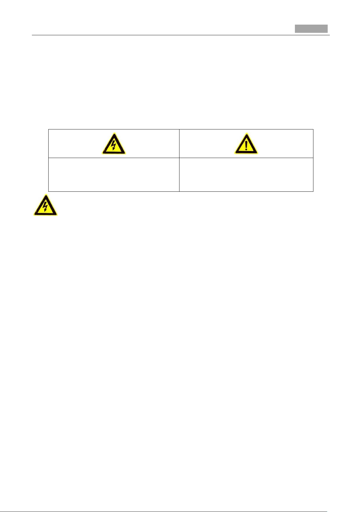
Warnings Follow these safeguards to
prevent serious injury or death.
Cautions Follow these precautions to
prevent potential injury or material
damage.
Safety Instruction
These instructions are intended to ensure that the user can use the product correctly to avoid danger
or property loss.
The precaution measure is divided into ‘Warnings’ and ‘Cautions’:
Warnings: Serious injury or death may be caused if any of these warnings are neglected.
Cautions: Injury or equipment damage may be caused if any of these cautions are neglected.
Warnings:
Please adopt the power adapter which can meet the safety extra low voltage (SELV) standard.
And source with 12 VDC or 24 VAC (depending on models) according to the IEC60950-1 and
Limited Power Source standard.
If the product does not work properly, please contact your dealer or the nearest service center.
Never attempt to disassemble the camera yourself. (We shall not assume any responsibility for
problems caused by unauthorized repair or maintenance.)
To reduce the risk of fire or electrical shock, do not expose this product to rain or moisture.
This installation should be made by a qualified service person and should conform to all the local
codes.
Please install blackouts equipment into the power supply circuit for convenient supply
interruption.
Please make sure that the ceiling can support more than 50(N) Newton gravities if the camera is
fixed to the ceiling.
If the product does not work properly, please contact your dealer or the nearest service center.
Never attempt to disassemble the camera yourself. (We shall not assume any responsibility for
problems caused by unauthorized repair or maintenance.)
Page 5
Installation Manual of Network Camera
4
Cautions:
Make sure the power supply voltage is correct before using the camera.
Do not drop the camera or subject it to physical shock.
Do not touch sensor modules with fingers. If cleaning is necessary, use a clean cloth with a bit of
ethanol and wipe it gently. If the camera will not be used for an extended period of time, put on
the lens cap to protect the sensor from dirt.
Do not aim the camera lens at the strong light such as sun or incandescent lamp. The strong light
can cause fatal damage to the camera.
The sensor may be burned out by a laser beam, so when any laser equipment is being used, make
sure that the surface of the sensor not be exposed to the laser beam.
Do not place the camera in extremely hot, cold temperatures (the operating temperature should
be between -30°C ~ 60°C, or -40°C ~ 60°C if the camera model has an “H” in its suffix), dusty
or damp environment, and do not expose it to high electromagnetic radiation.
To avoid heat accumulation, good ventilation is required for a proper operating environment.
Keep out of water and any liquid.
While shipping, the camera should be packed in its original packing.
Improper use or replacement of the battery may result in hazard of explosion. Please use the
manufacturer recommended battery type.
For the dome camera that supports IR, you are required to pay attention to the following precautions
to prevent IR reflection:
Dust or grease on the dome cover will cause IR reflection. Please do not remove the dome cover
film until the installation is finished. If there is dust or grease on the dome cover, clean the dome
cover with clean soft cloth and isopropyl alcohol.
Make certain the installation location does not have reflective surfaces of objects too close to the
camera. The IR light from the camera may reflect back into the lens causing reflection.
The foam ring around the lens (for dome cameras) must be seated flush against the inner surface
of the bubble to isolate the lens from the IR LEDS. Fasten the dome cover to camera body so that
the foam ring and the dome cover are attached seamlessly.
Page 6

Installation Manual of Network Camera
5
Table of Contents
Chapter 1 Introduction ................................................................................................................................ 7
1.1 Applications ......................................................................................................................................... 7
1.2 Preparations .......................................................................................................................................... 7
Chapter 2 Box Camera Installation ............................................................................................................ 9
2.1 Type I Box Camera .............................................................................................................................. 9
2.1.1 Camera Description ......................................................................................................................... 9
2.1.2 Installation....................................................................................................................................... 11
2.2 Type II Box Camera ........................................................................................................................... 12
2.2.1 Camera Description ....................................................................................................................... 12
2.2.2 Installation...................................................................................................................................... 14
Chapter 3 Dome Camera Installation ....................................................................................................... 19
3.1 Type I Dome Camera ......................................................................................................................... 19
3.1.1 Camera Description ....................................................................................................................... 19
3.1.2 Installation...................................................................................................................................... 20
3.2 Type II Dome Camera ........................................................................................................................ 26
3.2.3 Camera Description ....................................................................................................................... 26
3.2.4 Installation...................................................................................................................................... 27
3.3 Type III Dome Camera ....................................................................................................................... 30
3.3.1 Camera Description ....................................................................................................................... 30
3.3.2 Installation...................................................................................................................................... 31
3.4 Type IV Dome Camera ....................................................................................................................... 36
3.4.1 Camera Description ....................................................................................................................... 36
3.4.2 Installation...................................................................................................................................... 37
3.5 Type V Dome Camera ........................................................................................................................ 46
3.5.1 Camera Description ....................................................................................................................... 46
3.5.2 Installation...................................................................................................................................... 47
3.6 Type VI Dome Camera ....................................................................................................................... 49
3.6.1 Camera Description ....................................................................................................................... 49
3.6.2 Installation...................................................................................................................................... 51
3.7 Type VII Dome Camera ..................................................................................................................... 59
3.7.1 Camera Description ....................................................................................................................... 59
3.7.2 Installation...................................................................................................................................... 61
3.8 Type VIII Dome Camera .................................................................................................................... 65
3.8.1 Camera Description of Type A Dome Camera ............................................................................... 65
3.8.2 Installation of Type A Dome Camera ............................................................................................. 66
3.8.3 Camera Description of Type B Dome Camera ............................................................................... 69
3.8.4 Installation of Type B Dome Camera ............................................................................................. 69
3.9 Type IX Dome Camera ...................................................................................................................... 72
3.9.1 Camera Description ....................................................................................................................... 72
3.9.2 Installation...................................................................................................................................... 73
Page 7

Installation Manual of Network Camera
6
Chapter 4 Bullet Camera Installation ....................................................................................................... 83
4.1 Type I Bullet Camera ......................................................................................................................... 83
4.1.1 Camera Description ....................................................................................................................... 83
4.1.2 Installation...................................................................................................................................... 84
4.2 Type II Bullet Camera ........................................................................................................................ 85
4.2.1 Camera Description ....................................................................................................................... 85
4.2.2 Installation...................................................................................................................................... 86
4.3 Type III Bullet Camera ....................................................................................................................... 89
4.3.1 Camera Description ....................................................................................................................... 89
4.3.2 Installation...................................................................................................................................... 89
4.4 Type IV Bullet Camera ....................................................................................................................... 91
4.4.1 Camera Description ....................................................................................................................... 91
4.4.2 Installation...................................................................................................................................... 92
4.5 Type V Bullet Camera ........................................................................................................................ 93
4.5.1 Camera Description ....................................................................................................................... 93
4.5.2 Installation...................................................................................................................................... 94
4.6 Type VI Bullet Camera ..................................................................................................................... 100
4.6.1 Camera Description ..................................................................................................................... 100
4.6.2 Installation.................................................................................................................................... 101
4.7 Type VII Bullet Camera ................................................................................................................... 104
4.7.1 Camera Description ..................................................................................................................... 104
4.7.2 Installation.................................................................................................................................... 106
Chapter 5 Turret Camera Installation ..................................................................................................... 112
5.1 Camera Description ........................................................................................................................... 112
5.2 Installation ......................................................................................................................................... 112
Chapter 6 Cube Camera Installation ....................................................................................................... 117
6.1 Type I Cube Camera .......................................................................................................................... 117
6.1.1 Camera Description ...................................................................................................................... 117
6.1.2 Installation..................................................................................................................................... 118
6.2 Type II Cube Camera ........................................................................................................................ 119
6.2.1 Camera Description ...................................................................................................................... 119
6.2.2 Remote Control Overview ............................................................................................................ 121
6.2.3 Installation.................................................................................................................................... 121
6.3 Type III Cube Camera ...................................................................................................................... 124
6.3.1 Camera Description ..................................................................................................................... 124
6.3.2 Notice............................................................................................................................................ 125
6.3.3 Installation.................................................................................................................................... 127
Page 8

Installation Manual of Network Camera
7
Chapter 1 Introduction
The network camera is a kind of embedded digital surveillance product that combines the features of
both traditional analog camera and the encoder. With a built-in video server, the network camera is
capable of providing real-time video stream compression, processing, video analysis and
transmission simultaneously. Adopting the latest processing chip and hardware platform, the network
camera can be widely applied to various surveillance and image processing systems with high
reliability and stability.
1.1 Applications
The network camera can be used in many surveillance scenes., e.g.:
Network surveillance for over-the-counter activities in the banks, ATMs, supermarkets and
factories.
Remote surveillance systems for nursing homes, kindergartens and schools.
Artificial Intelligent access control systems .
Artificial Intelligent office building/residential compounds management systems.
Unguarded power station and telecommunication base station surveillance systems.
Pipelining and warehousing monitoring systems.
Surveillance systems for airports, railway stations, bus stops, etc.
1.2 Preparations
Make sure the device in the package is in good condition and all the assembly parts are included.
Make sure all the related equipment is power-off during the installation.
Check the specification of the products for the installation environment.
Make sure the power supply is matched with your required voltage to avoid damage.
If the product does not function properly, please contact your dealer or the nearest service center.
Do not disassemble the camera for repair or maintenance by yourself.
Make sure that the wall is strong enough to withstand three times the weight of the camera.
For the camera that supports IR, you are required to pay attention to the following precautions to
prevent IR reflection:
Dust or grease on the dome cover will cause IR reflection. Please do not remove the dome cover
film until the installation is finished. If there is dust or grease on the dome cover, clean the dome
cover with clean soft cloth and isopropyl alcohol.
Page 9

Installation Manual of Network Camera
8
Make sure that there is no reflective surface too close to the camera lens. The IR light from the
camera may reflect back into the lens causing reflection.
The foam ring around the lens must be seated flush against the inner surface of the bubble to
isolate the lens from the IR LEDS. Fasten the dome cover to camera body so that the foam ring
and the dome cover are attached seamlessly.
Page 10
Installation Manual of Network Camera
9
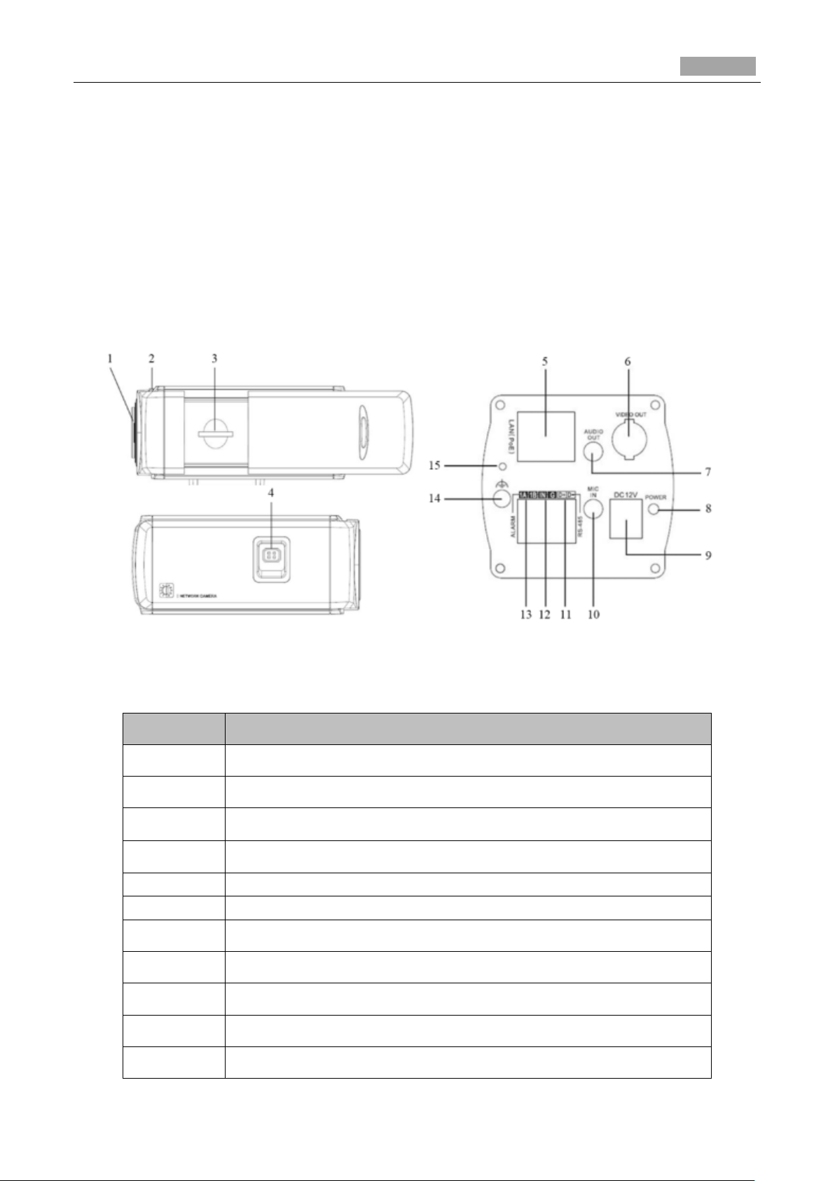
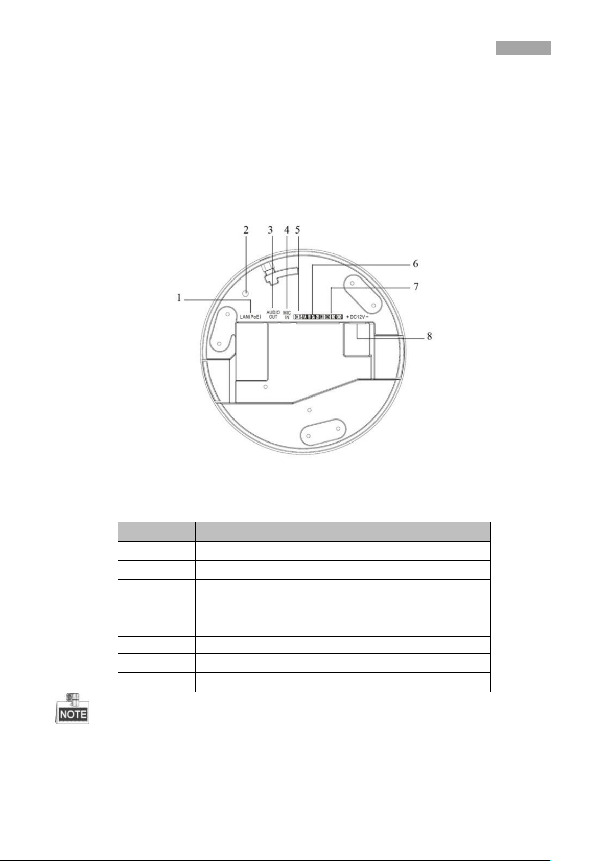
No.
Description
1
Lens Mount
2
Back Focus Ring
3
SD Card Slot
4
Auto-iris Interface
5
10M/100M Self-adaptive Ethernet Interface
6
VIDEO OUT: Video Output Interface
7
AUDIO OUT: Audio Output Interface
8
POWER: Power LED Indicator
9
Power Supply Interface
10
MIC IN: Audio Input Interface
11
D+, D-: RS-485 Interface
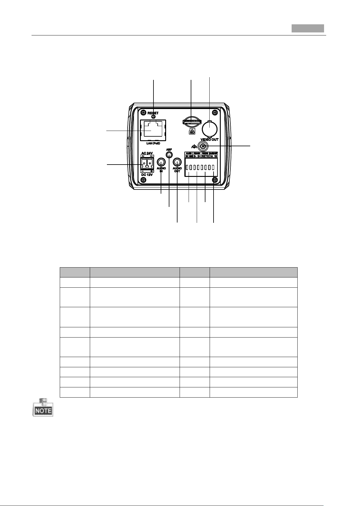
Chapter 2 Box Camera Installation
2.1 Type I Box Camera
2.1.1 Camera Description
The overview of Type I box camera is shown below:
Figure 2-1 Overview
Table 2-1 Description
Page 11
Installation Manual of Network Camera
10
No.
Description
12
IN, G: Alarm Input Interface
13
1A, 1B: Alarm Output Interface
14
Grounding
15
RESET: Reset Button
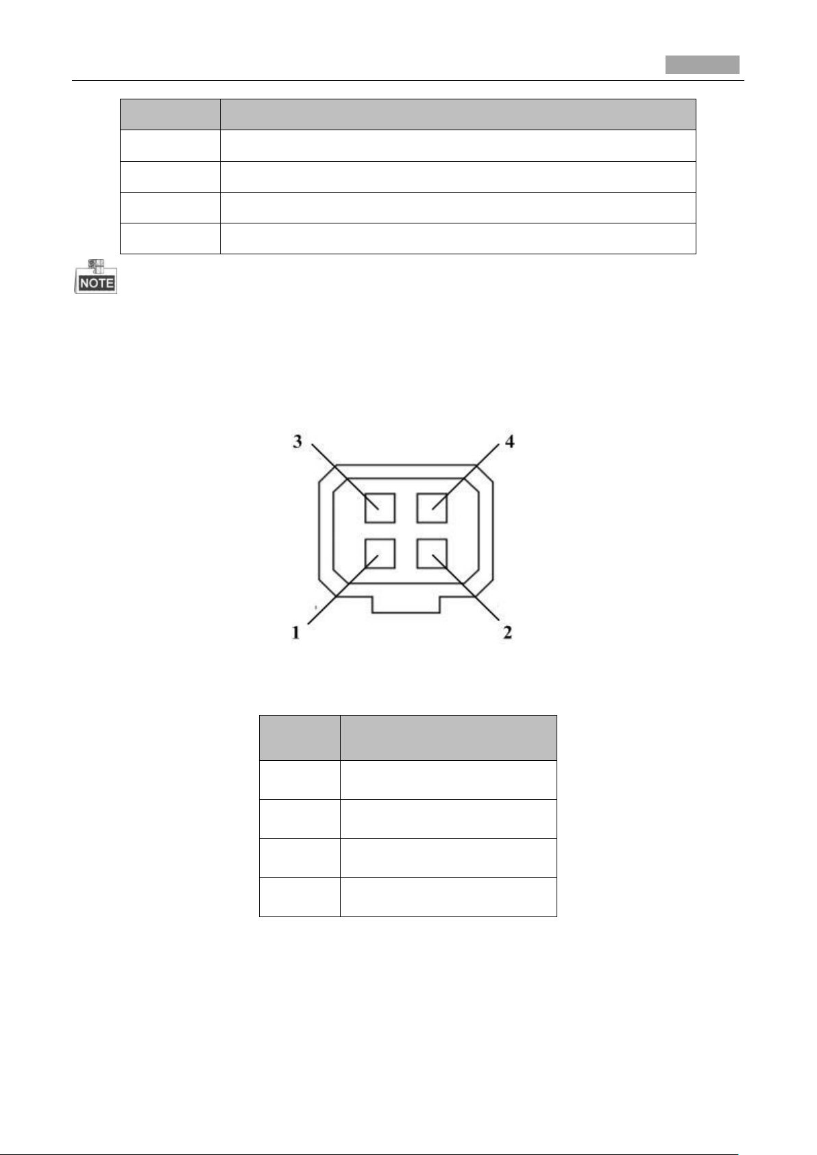
No.
DC-driven
1
Damp-
2
Damp+
3
Drive+
4
Drive-
Press RESET about 10s when the camera is powering on or rebooting to restore the default settings,
including the user name, password, IP address, port No., etc.
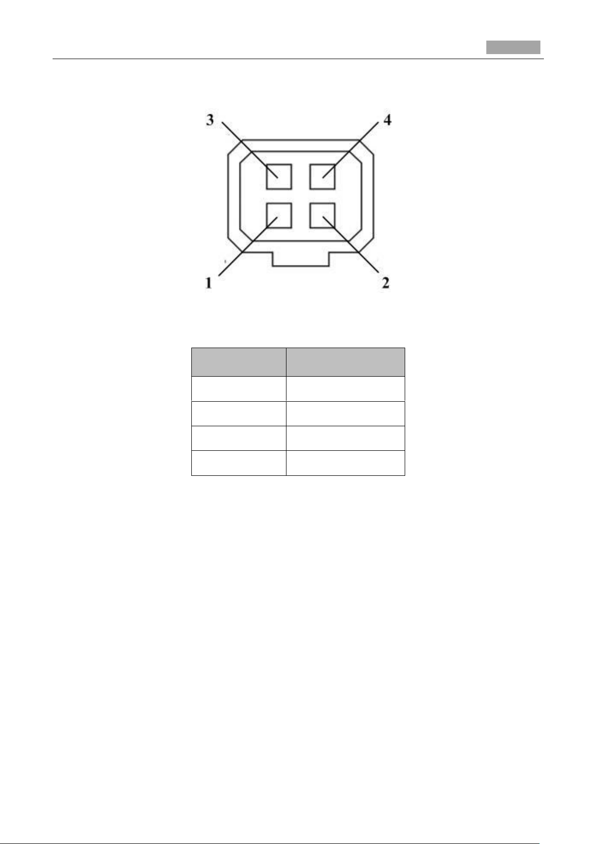
The type of auto-iris interface is shown as below figure:
Figure 2-2 Auto-iris Interface
Table 2-2 Pins
Power, Video and GND pins are used when the auto-iris is driven by video; And Damp+, Damp-,
Drive+ and Drive- pins are used when the auto-iris is driven by DC.
Page 12
Installation Manual of Network Camera
11
Expansion Screw
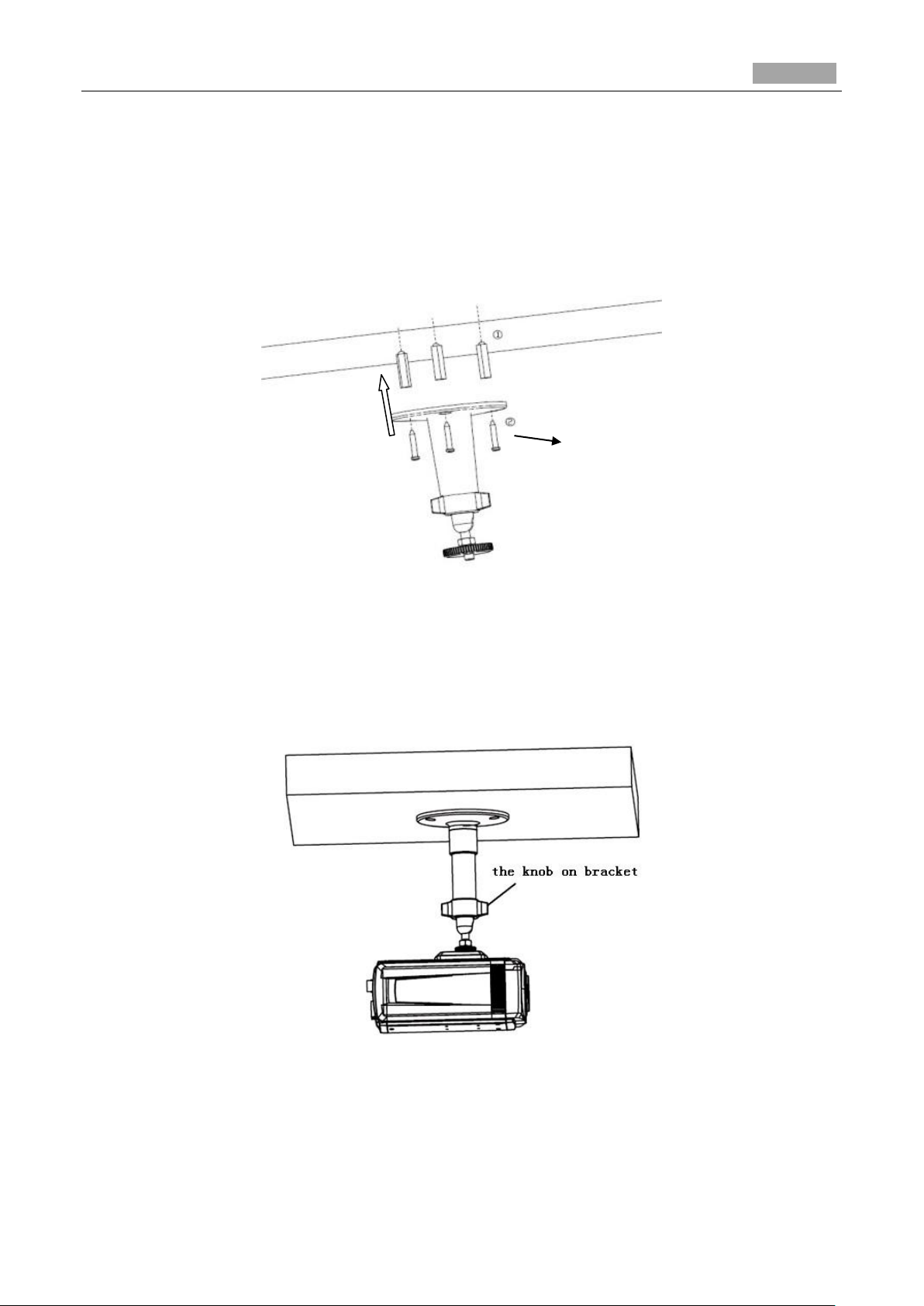
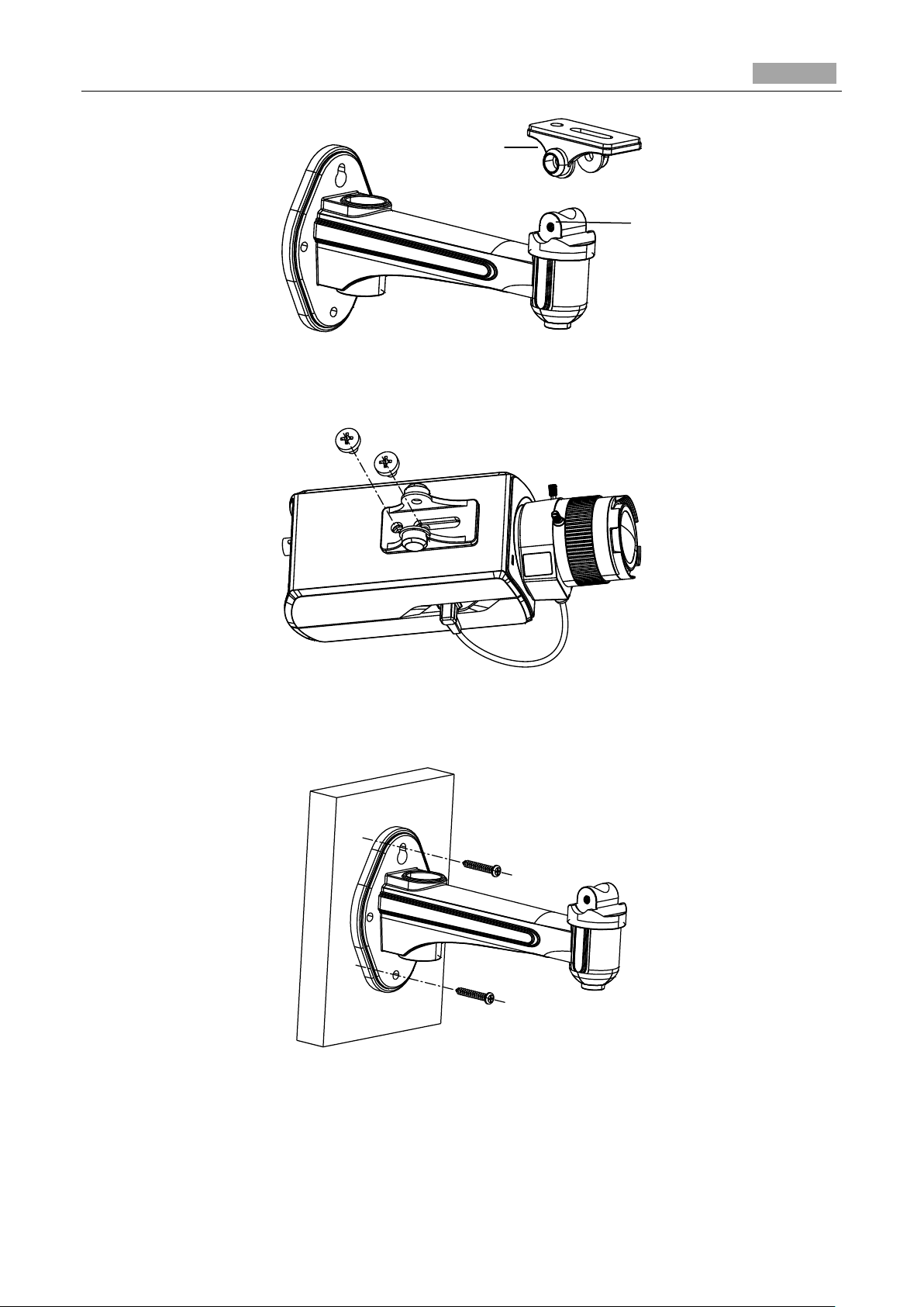
2.1.2 Installation
Steps:
1. Fix the mounting bracket to the ceiling.
Figure 2-3 Fix Camera Mounting Bracket
2. Aim the screw hole on the camera at the bracket and rotate the camera tightly.
3. Adjust the camera to the desired surveillance angle and tighten the knob on bracket to secure the
camera.
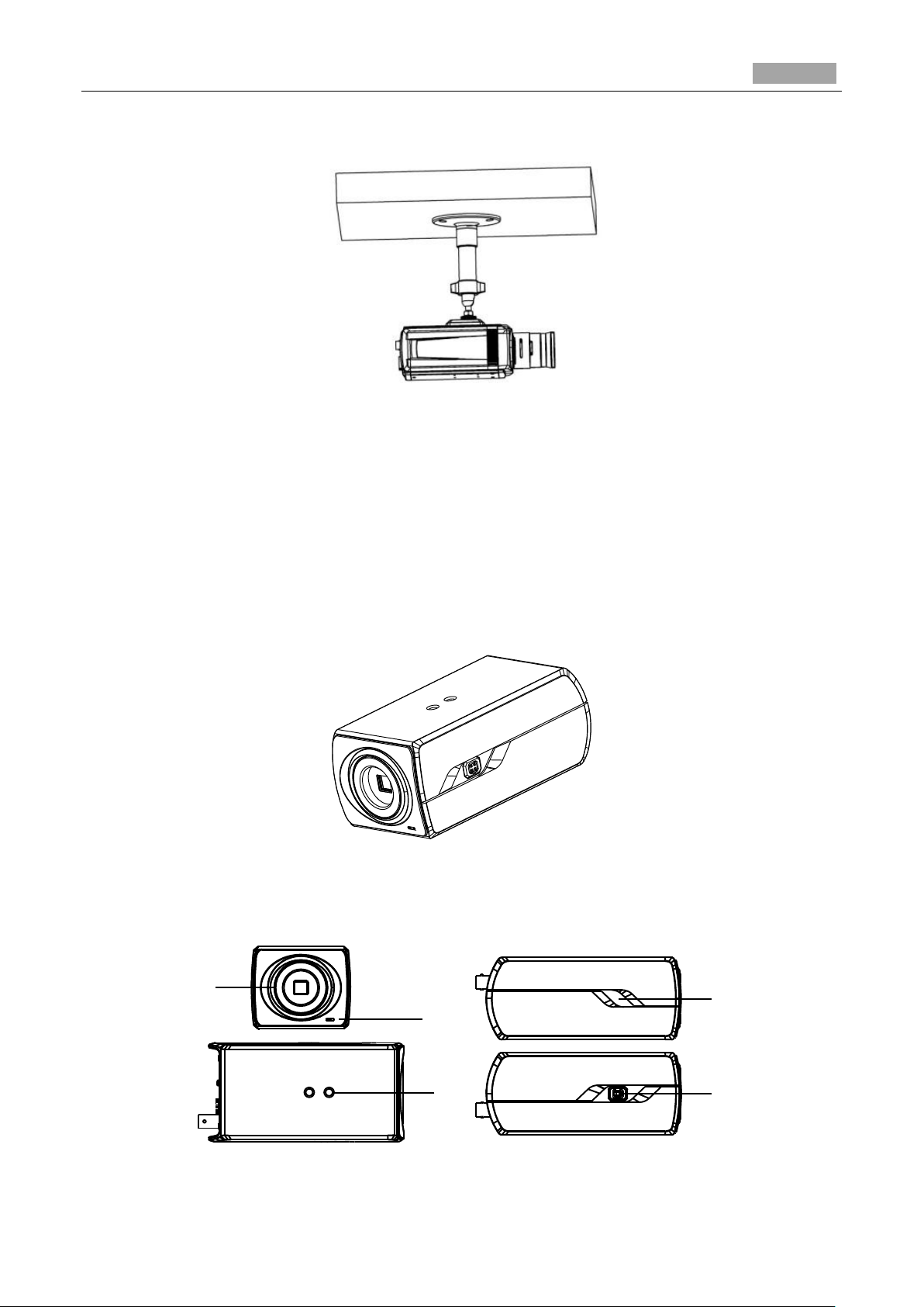
4. Install the lens.
1). Connect the VIDEO OUT interface of the camera to the debugging monitor.
Figure 2-4 Fix the Camera
Page 13
Installation Manual of Network Camera
12
1
2
4
3
5
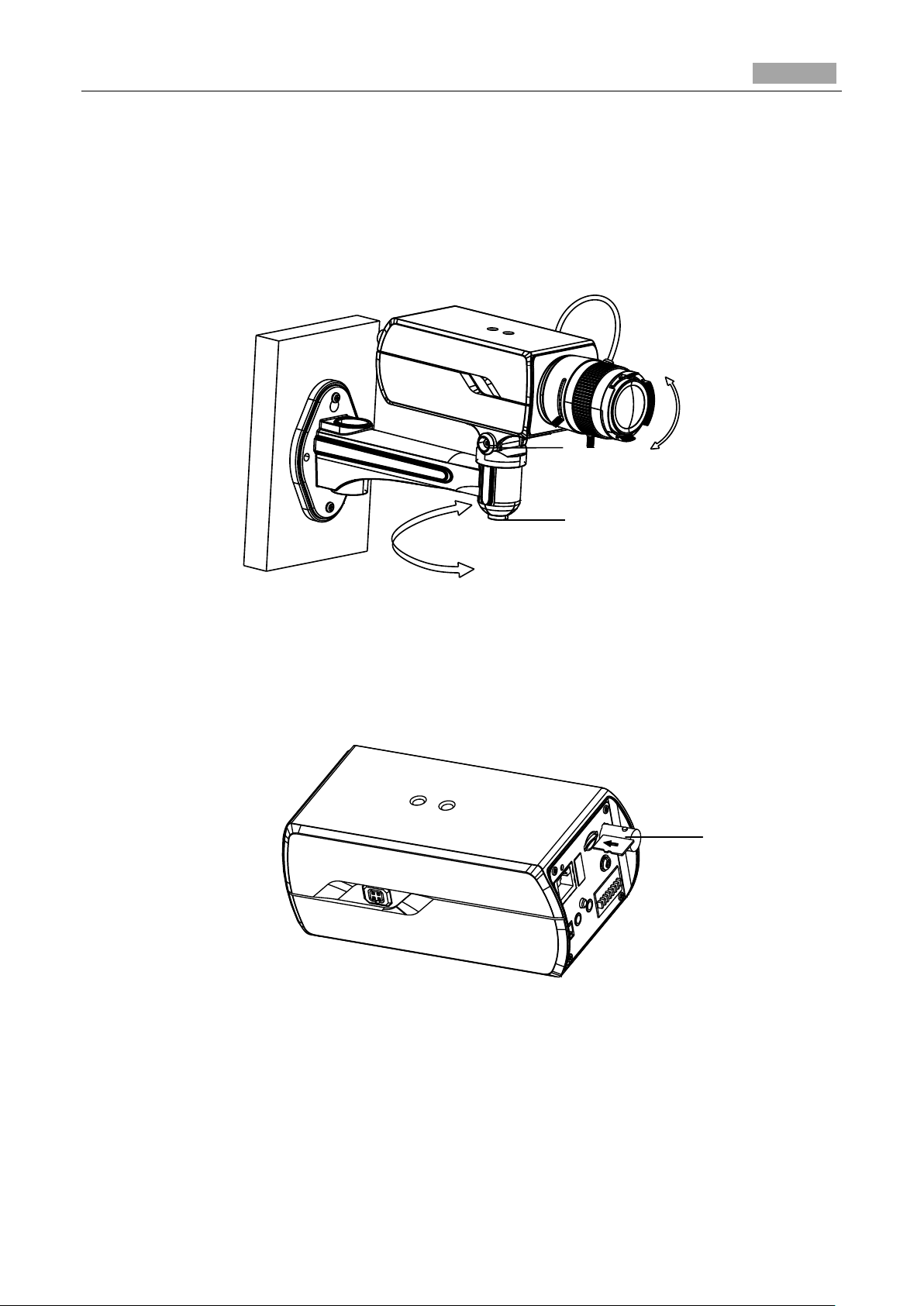
2). Adjust the lens focus to obtain a perfect image on the monitor.
Figure 2-5 Install the Lens
2.2 Type II Box Camera
2.2.1 Camera Description
The overview of Type II box camera is shown below:
Figure 2-6 Overview (1)
The overview of the components and the interface are shown below:
Figure 2-7 Overview (2)
Page 14
Installation Manual of Network Camera
13
8
6
9
10
7
18
16
11
17
14
13
15
12
No.
Description
No.
Description
1
Lens Mount
2
MIC
3
¼-20 UNC Screw Hole
4
Status Indicator
5
Auto-iris Interface
6
LAN(PoE)
7
Power Outlet
8
Reset
9
Micro SD Card Slot
10
Video Out
11
Grounding
12
Alarm Out
13
RS-232
14
RS-485
15
Alarm In
16
Audio Out
17
ABF
18
Audio In
The interfaces on the rear panel are shown below:
Figure 2-8 Overview (3)
Table 2-3 Description
Press RESET about 10s when the camera is powering on or rebooting to restore the default settings,
including the user name, password, IP address, port No., etc.
Page 15
Installation Manual of Network Camera
14
No.
DC-driven
1
Damp-
2
Damp+
3
Drive+
4
Drive-
The type of auto-iris interface is shown as below figure:
Figure 2-9 Auto-iris Interface
Table 2-4 Pins
Power, Video and GND pins are used when the auto-iris is driven by video; Damp+, Damp-, Drive+
and Drive- pins are used when the auto-iris is driven by DC.
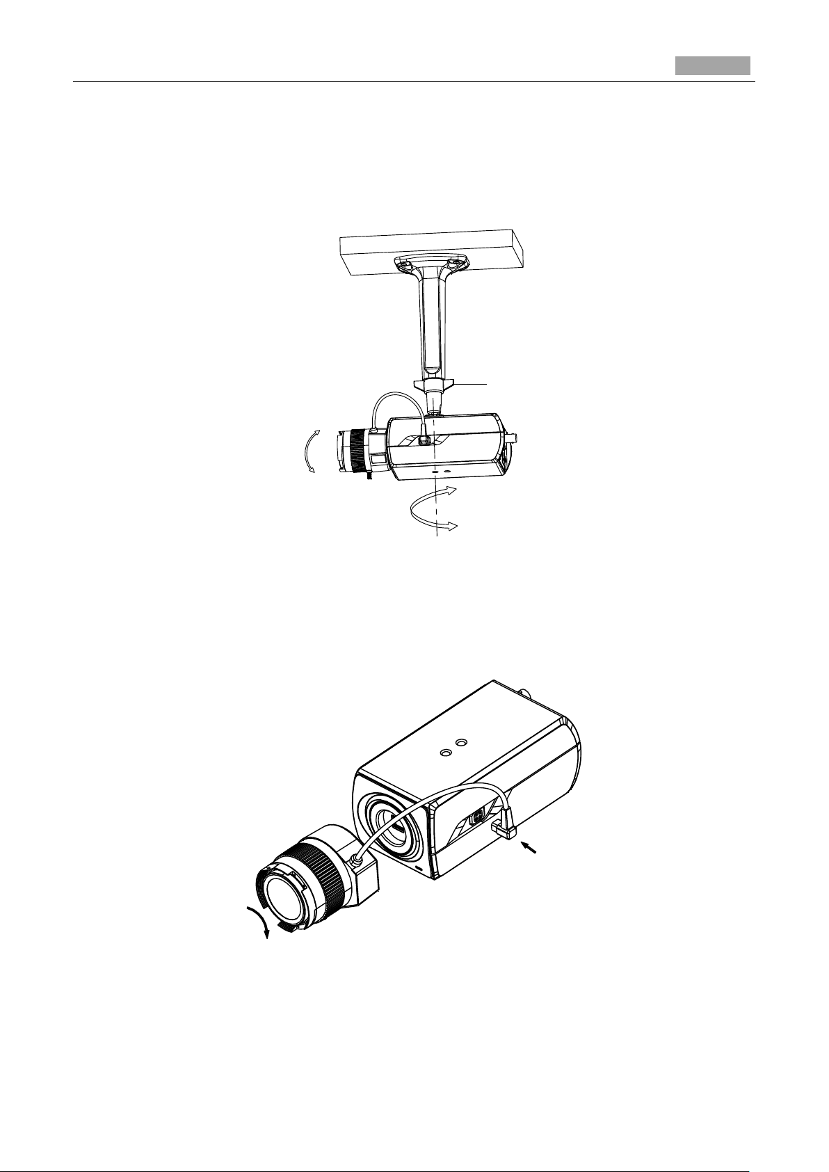
2.2.2 Installation
Ceiling Mounting
Steps:
1. Install the ceiling mount to the ceiling with the supplied expansion screws.
Page 16
Installation Manual of Network Camera
15
Adjustable Nut
Figure 2-10 Install the Mount
2. Fit the lens (not supplied) to the camera and rotate it to get it tightened.
● Install the adapter ring to the lens interface if a C-mount lens is used.
● A manual-iris lens can be directly installed to the camera without plugging the power cable of
the auto-iris to the auto-iris interface.
3. Plug the auto-iris cable to the auto-iris interface.
4. Align the screw hole on the camera with the ceiling mount and rotate the camera to get it fixed.
5. Adjust the surveillance angle.
1). Loosen the pan nut to adjust the pan angle [0°-360°].
Figure 2-11 Install the Lens
Page 17
Installation Manual of Network Camera
16
Knob
2). Loosen the knob on the ceiling mount to adjust the tilt angle [0°-90].
6. Adjust the Lens
1). Connect the VIDEO OUT interface of the camera to the debugging monitor.
2). Adjust the Zoom Lever and Focus Lever to obtain a perfect image on the monitor.
Figure 2-12 Install the Camera to the Mount and Adjust the Angle
Wall Mounting
1. Install the lens (not supplied) to the camera and rotate it to get it tightened.
2. Plug the auto-iris cable to the auto-iris interface.
Figure 2-13 Install the Lens
3. Loosen the lock screw on the mount and remove the tilt adjust table from the wall mount.
Page 18
Installation Manual of Network Camera
17
Tilt Adjust Table
Lock Screw
Figure 2-14 Remove the Tilt Adjust Table
4. Fit the removed tilt adjust table to the camera, and fix it with two screws.
Figure 2-15 Install the Tilt Adjust Table
5. Secure the wall mount to the wall with the supplied expansion screws.
Figure 2-16 Install the Wall Mount
6. Install the camera to the wall mount and tighten the two lock screws.
7. Adjust the surveillance angle.
Page 19
Installation Manual of Network Camera
18
Tilt Adjust Nut
Pan Adjust Nut
SD Card
1). Loosen the pan nut to adjust the pan angle [0 °-360°].
2). Loosen the knob on the ceiling mount to adjust the tilt angle [0°-±45°].
8. Adjust the Lens
1). Connect the VIDEO OUT interface of the camera to the debugging monitor.
2). Adjust the focus lever to obtain a perfect image on the monitor.
Figure 2-17 Adjust the Surveillance Angle
Installing the SD Card
● Insert the SD card to the SD card slot to get it installed.
● Push the inserted SD card slightly to get it sprung by its built-in springing to remove it.
Figure 2-18 Install the SD Card
Page 20
Installation Manual of Network Camera
19
No.
Description
1
10M/100M self-adaptive Ethernet interface
2
Reset Button
3
AUDIO OUT: Audio output interface
4
MIC IN: Audio input interface
5
D+, D-: RS-485 interface
6
1A, 1B, 2A, 2B: Alarm output interface
7
IN1, GND, IN2, GND: Alarm input interface
8
Power Supply Interface
Chapter 3 Dome Camera Installation
3.1 Type I Dome Camera
3.1.1 Camera Description
Figure 3-1 Overview
Table 3-1 Description
Press RESET about 10s when the camera is powering on or rebooting to restore the default settings,
including the user name, password, IP address, port No., etc.
Page 21
Installation Manual of Network Camera
20
1
1
1
1
Drill Template
A
Screw hole 1: for Mounting Base
Hole A: for cables routed
through the ceiling
Code:190600249
3.1.2 Installation
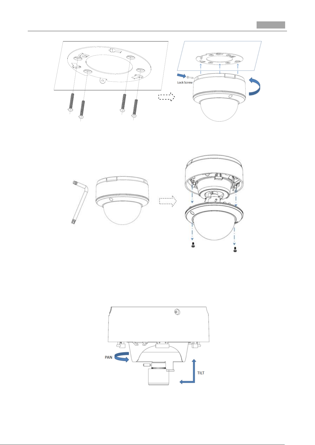
Ceiling Mounting
Steps:
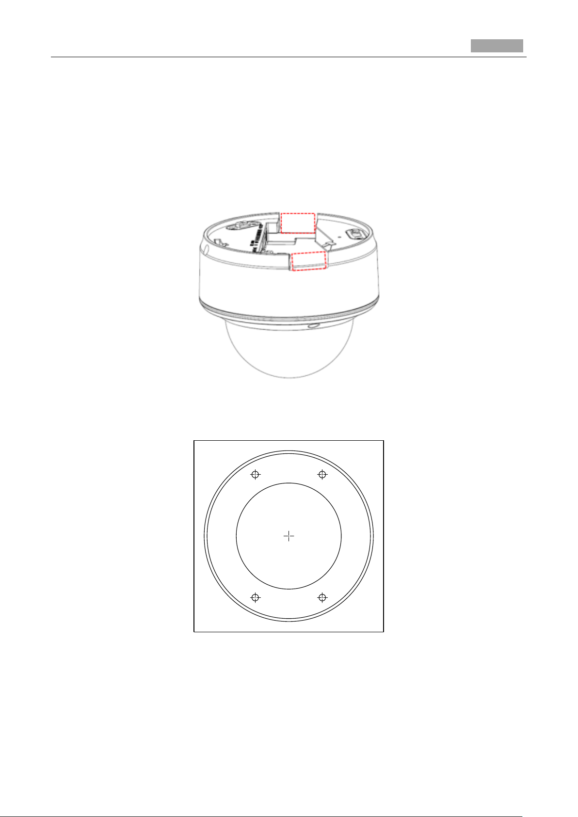
1. (Optional) use a plier to remove one clip or both two clips (marked in dotted line in Figure 3-2) on
the side of the back box and then route cables through the opening to secure the cables on the
ceiling.
Figure 3-2 Side Clips
2. Drill the screw hole and the cable hole according to the supplied drill template.
Figure 3-3 Drill Template
3. Fix the mounting base to the ceiling; rotate the back box counterclockwise to secure it to the
mounting base; use the lock screw to secure the dome camera.
Page 22
Installation Manual of Network Camera
21
Figure 3-4 Mounting
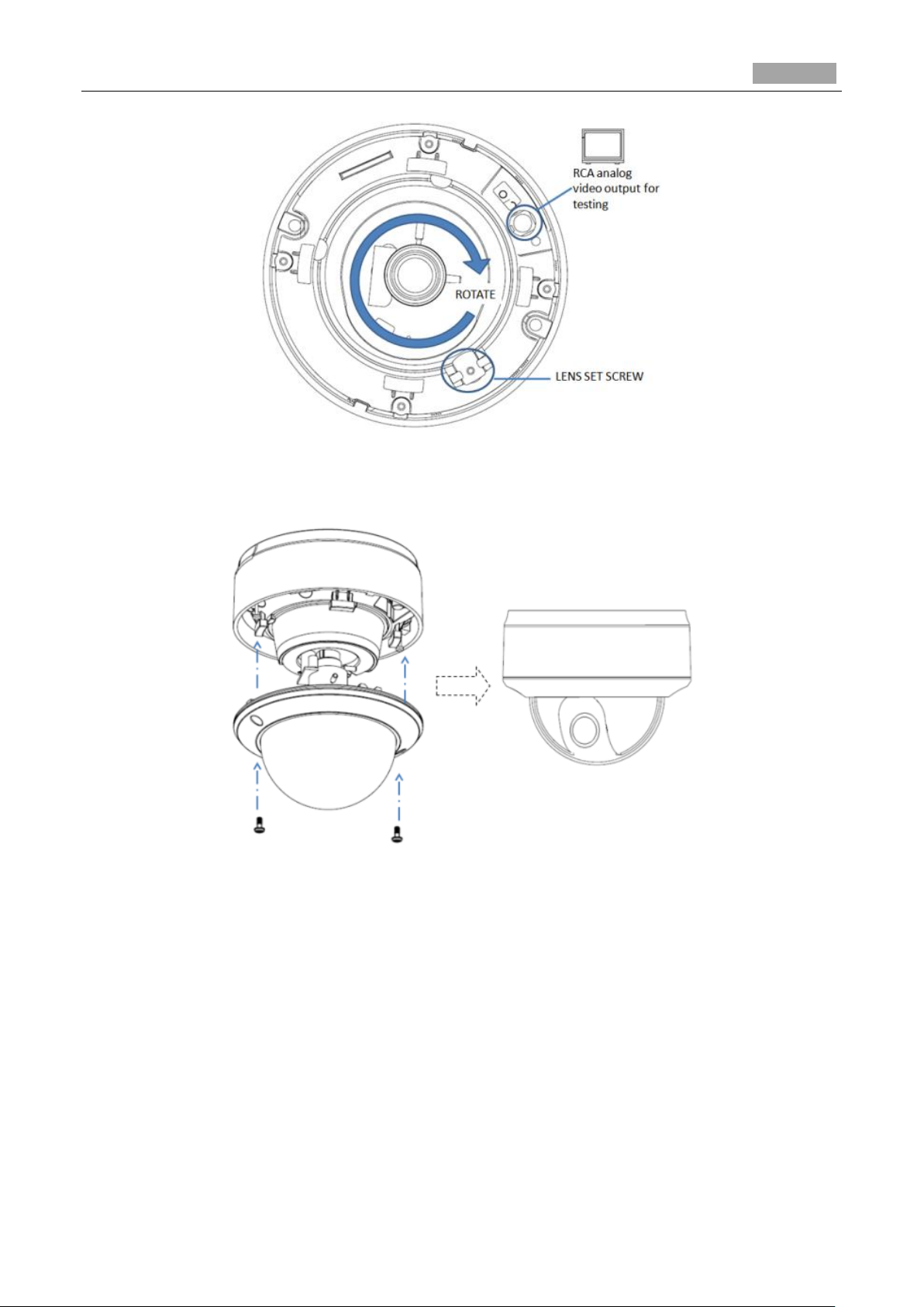
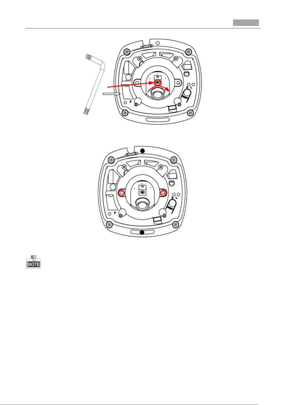
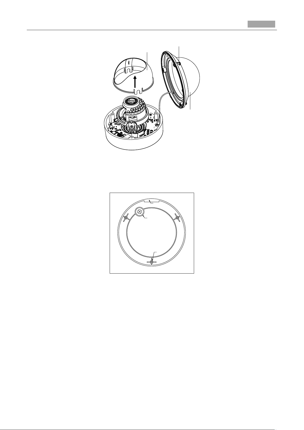
4. Loosen the set screws with the hex key (supplied) to remove the bubble.
Figure 3-5 Disassembling
5. Connect the RCA analog video output with a monitor to view the image of the camera. Loosen the
lens set screw to adjust the angle of pan, tilt and rotation direction.
6. Adjust the focus to obtain a perfect image. Fasten the lens set screw.
Figure 3-6 Image Adjusting
Page 23
Installation Manual of Network Camera
22
Figure 3-7 Image Adjusting
7. Reinstall the bubble and tighten the screws.
Figure 3-8 Reinstall
In-ceiling mounting
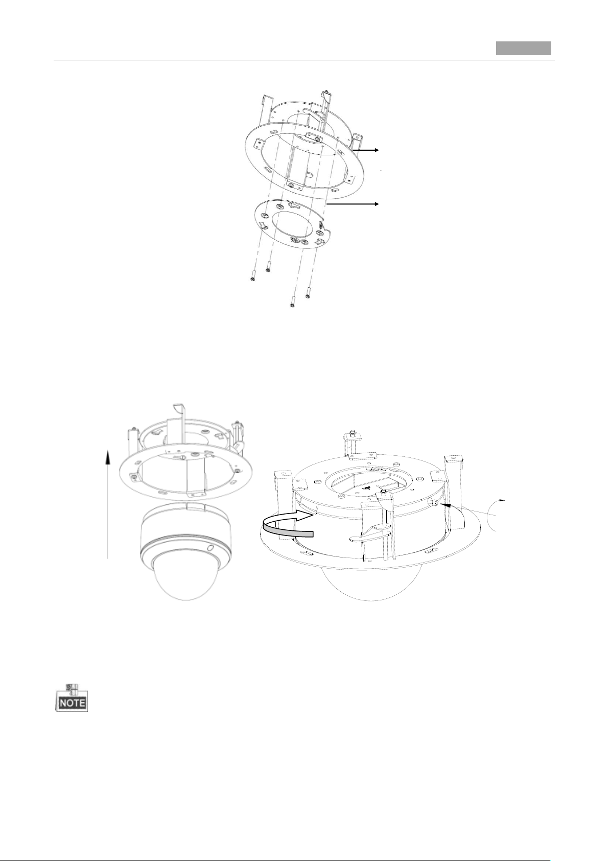
Steps:
1. Secure the mounting base to the in-ceiling mounting base with screws.
Page 24
Installation Manual of Network Camera
23
In-ceiling
Mounting
Mounting
Base
①
②
③
Lock screw
Figure 3-9 Mounting Base
2. Push the dome camera to the in-ceiling mounting base, rotate the dome camera for 10 degrees
counterclockwise and then fasten the lock screws to fix the camera.
Figure 3-10 Camera and Mounting Base
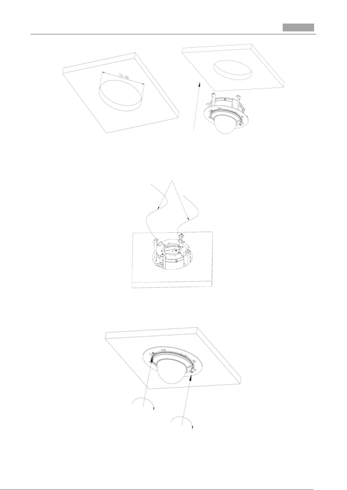
3. Cut a 176~180 mm diameter hole in the ceiling and push the dome camera with in-ceiling
mounting base to the hole.
The thickness of the ceiling should be less than 30 mm.
Page 25
Installation Manual of Network Camera
24
Safety Rope
Lock Screw
Figure 3-11 Installing
4. It is strongly recommended that you use a safety rope to secure the in-ceiling mounting base to the
roof.
Figure 3-12 Safety Rope
5. Fasten the lock screws to secure the dome camera.
Figure 3-13 Fasten Screws
Page 26
Installation Manual of Network Camera
25
6. Remove the bubble and connect the RCA analog video output with a monitor to view the image of
the camera. Loosen the lens set screw and pan, tilt or rotate the lens to get a desired surveillance
angle. Adjust the lens focus to obtain a perfect image. Fasten the lens set screw. Reinstall the
bubble.
Figure 3-14 Image Adjusting
7. Install the trim plate with screws to finish the installation.
Figure 3-15 Trim Plate Installing
Page 27
Installation Manual of Network Camera
26
No.
Description
1
Cover
2
Lens
3
Power LED indicator, It turns solid red when power is connected.
4
Base plate
5
Set screw hole
6
Set screw of lens
7
S & L: Network status indicator.
When the network is connected, the “S” LED is solid yellow, while the “L”
LED flashes orange.
8
RESET Button
3.2 Type II Dome Camera
3.2.3 Camera Description
Figure 3-16 Overview
Table 3-2 Physical Description
Press RESET button about 10s when the camera is powering on or rebooting to restore the default
settings, including the user name, password, IP address, port No., etc.
Page 28
Installation Manual of Network Camera
27
3.2.4 Installation
Steps:
1. (Optional) Use a plier to remove the clip (marked in dotted line in 0) on the side of the back box
and then route the cables through the opening instead of the cable hole.
Figure 3-17 Side Clip
2. Loosen the set screws with a hex key (supplied) to remove the cover.
Figure 3-18 Remove the Cover
3. Fix the camera to the ceiling with the supplied screws.
Page 29
Installation Manual of Network Camera
28
Figure 3-19 Fix the Camera
4. View the video image of the camera over the network.
5. Loosen the lens set screws.
Figure 3-20 Loosen the Lens Set Screws
6. Insert the hex key into the hole marked in the picture and rotate the hex key to adjust the panning
position and tilting position until getting the desired surveillance angle. Tighten the set screws.
Page 30
Installation Manual of Network Camera
29
Figure 3-21 Adjust Panning Position
Figure 3-22 Adjust Tilting Position
As the lens of camera has already been factory adjusted to the best imaging effect, you just need to
adjust the panning position and tilting position to get the desired surveillance angle.
7. Reinstall the cover before viewing the image so that you can get the same surveillance effect as
the installation is done.
8. Install the cover, and tighten the set screws.
Page 31

Installation Manual of Network Camera
30
Figure 3-23 Install the Back Box
3.3 Type III Dome Camera
3.3.1 Camera Description
Figure 3-24 Overview
Page 32

Installation Manual of Network Camera
31
No.
Description
1
Ceiling Mount
2
Lock Button
3
Mounting Base
4
SD Card Slot
5
Lens
6
IR LED
7
Bubble
8
Status Indicator
9
RCA Analog Video Output
10
Debug
11
Reset
Table 3-3 Description
Press RESET about 10s when the camera is powering on or rebooting to restore the default settings,
including the user name, password, IP address, port No., etc.
3.3.2 Installation
Steps:
1. Drill the screw holes and the cable hole in the ceiling according to the supplied drill template.
Page 33

Installation Manual of Network Camera
32
Ceiling
Ceiling Mount
Figure 3-25 Drill Template
2. Fix the ceiling mount to the ceiling with screws.
3. Route the cables through the cable hole on the ceiling.
If required, you can rotate the side outlet on the mounting base to remove it and route the cables
through the side outlet.
Figure 3-26 Fix the Ceiling Mount
Page 34

Installation Manual of Network Camera
33
Unlock Button
Screw
Hole
Side Outlet
Figure 3-27 Side Outlet
4. Insert the three screws on the mounting base into the corresponding holes on the ceiling mount.
5. Rotate the mounting base clockwise to secure the dome camera to the ceiling mount.
Figure 3-28 Install the Dome Camera
To uninstall the dome camera, press the lock button and rotate the mounting base
counterclockwise.
Page 35

Installation Manual of Network Camera
34
A
3:1
A
Figure 3-29 Uninstall the Dome Camera
6. Loosen the set screws with a hex key (supplied) to remove the bubble.
Figure 3-30 Remove the Bubble
7. Connect the RCA analog video output with a monitor to view the image.
8. Loosen the set screw and adjust the panning position and tilting position until you get the desired
surveillance angle.
9. Loosen the zoom puller and focus puller and adjust the lens focus to obtain a perfect image.
Page 36

Installation Manual of Network Camera
35
RCA Analog Video
Output for Test
Set Screw
Zoom Puller
Focus Puller
Figure 3-31 Image Adjusting
10. Reinstall the bubble and tighten the screws to complete the installation.
Figure 3-32 Reinstallation
Page 37

Installation Manual of Network Camera
36
1
2
3
4
5
6
8
7
No.
Description
1
Video output interface
2
LINK: Indicator is solid yellow when network is
connected.
3
ACT: Indicator flashes blue when network
connection is functioning properly.
4
PWR: Indicator is solid red when the device is
powered on.
5
Micro SD slot
6
RESET: Reset the camera.
7
10M/100M self-adaptive Ethernet interface
8
Power supply interface
3.4 Type IV Dome Camera
3.4.1 Camera Description
Figure 3-33 Overview
Table 3-4 Physical Description
The extended interface can be connected to alarm input/output interface, audio input/output
interface, RS-485 interface, etc.
Page 38

Installation Manual of Network Camera
37
Drill Template
1
1
22
2
2
3
3
3
3
4 4
4
4
Screw hole 3: for
Mounting Base
Hole A: for cables routed
through the ceiling
Code:190600839
Press RESET about 10s when the camera is powering on or rebooting to restore the default
settings, including the user name, password, IP address, port No., etc.
3.4.2 Installation
Ceiling Mounting
Steps:
1. Drill the screw holes on the ceiling with the supplied drilling template. If you need to route the
cables from the bottom of the camera, cut a cable hole in the ceiling.
Figure 3-34 Drilling Template
2. Secure the back box to the ceiling with screws.
Figure 3-35 Mount Back Box
3. Loosen the set screws with the hex key (supplied) to remove the bubble; remove the black liner.
Page 39

Installation Manual of Network Camera
38
Figure 3-36 Disassembling
4. Install the dome drive to the back box and pull the cables through the cable outlet on the bottom
of the back box.
Figure 3-37 Dome Drive Installing
If you need to pull the cable through the side outlet of the camera, please remove the cover and use
water-proof joints and water-proof pipe to route the cables.
Page 40

Installation Manual of Network Camera
39
Outlet
Rotate
Pan
Tilt
Lock Screw
Figure 3-38 Side Cable Routing
5. After connecting the network cable and power cable, view the image of the camera over the
network. Loosen the lock screws; adjust the panning position and tilting position and rotate the lens
to get the desired surveillance angle; fasten the lock screws.
Figure 3-39 Angle Adjusting
6. Reinstall the black liner and bubble to finish the installation.
Figure 3-40 Reinstall
Page 41

Installation Manual of Network Camera
40
Drill Template
1
1
1
A
Hole A: for the recessed part of
the camera body
Screw hole 1: for Toggle bolt
Code:190600840
In-ceiling Mounting:
Steps:
1. Drill the screw holes and the cable hole on the ceiling according to the supplied drill template.
Figure 3-41 Drill Template
2. Loosen the set screws with the hex key (supplied) to remove the bubble; and remove the black
liner.
Figure 3-42 Disassembling
3. Rotate the toggle to remove it from the toggle bolt.
4. Insert the bolt into the toggle bolt hole on the dome drive and use the screw driver to rotate the
bolt slightly but not tightly.
5. Reinstall the toggle and push the dome drive to the cable hole on the ceiling with toggle bolts
aligned with the screw holes on the ceiling.
Page 42

Installation Manual of Network Camera
41
Toggle
Bolt
Ceiling
Figure 3-43 Dome Drive Installing
6. Fasten the toggle bolt and the toggle will automatically secure the dome drive to the ceiling.
Figure 3-44 Fasten Toggle Bolt
7. Connecting the network cable and power cable.
8. View the camera image over the network.
9. Loosen the lock screws to adjust the panning position and tilting position and rotate the lens to
get the desired surveillance angle.
10. Fasten the lock screws.
Page 43

Installation Manual of Network Camera
42
Rotate
Pan
Tilt
Lock Screw
Figure 3-45 Angle Adjusting
11. Reinstall the black liner and dome drive to finish the installation.
Figure 3-46 Complete the Installation
Page 44

Installation Manual of Network Camera
43
Drill Template
1
1
22
2
2
3
3
3
3
4 4
4
4
Screw hole 3: for
Mounting Base
Hole A: for cables routed
through the ceiling
Code:190600839
Wall mounting:
Steps:
1. Drill the screw holes and the cable hole on the wall according to the supplied drill template.
Figure 3-47 Drilling Template
2. Secure the back box to the wall with the supplied screws.
Position the side cable outlet directly below to prevent moisture from getting inside the camera.
3. Loosen the set screws with the hex key (supplied) to remove the bubble; remove the black liner.
Figure 3-48 Secure Back box
Page 45

Installation Manual of Network Camera
44
Side Outlet
Figure 3-49 Disassembling
4. Install the dome drive to the back box and pull the cables through the side outlet on the bottom of
the back box.
If you need to pull the cable through the cable outlet from the side of the camera, please remove the
cover and use water-proof joints and water-proof pipe to route the cables.
Figure 3-50 Side Cable Routing
5. Connecting the network cable and power cable.
Page 46

Installation Manual of Network Camera
45
Rotate
Pan
Tilt
Lock Screw
6. View the camera image over the network.
7. Loosen the lock screws to adjust the panning position and tilting position, and rotate the lens to get
the desired surveillance angle.
8. Fasten the lock screws.
Figure 3-51 Angle Adjusting
9. Reinstall the black liner and bubble to finish the installation.
Figure 3-52 Complete the Installation
Page 47

Installation Manual of Network Camera
46
2
3
4
6
7
8
9
5
1
No.
Description
1
Mounting Base
2
Horizontal Stand
3
Vertical Stand
4
Bubble
5
Power/Network Cables
6
IR LED
7
Lens
8
Black Liner
9
Safety Rope
3.5 Type V Dome Camera
3.5.1 Camera Description
Figure 3-53 Overview
Table 3-5 Description
Press RESET button about 10s when the camera is powering on or rebooting to restore the default
settings, including the user name, password, IP address, port No., etc.
Page 48

Installation Manual of Network Camera
47
Screw Hole
Screw Hole
Screw Hole
Ceiling Mounting
3.5.2 Installation
Steps:
1. Drill the screw holes on the ceiling according to the drill template.
Figure 3-54 Drilling Template
2. Loosen the set screws with a hex key (supplied) to remove the bubble.
Figure 3-55 Remove the Bubble
3. Fix the mounting base on the ceiling with screws.
Page 49

Installation Manual of Network Camera
48
Tilt Lock Screw
Black Liner
Pan
Tilt
Side Opening
Figure 3-56 Fix the Mounting Base
If required, you can route cables through the side opening on the side of the mounting base.
Figure 3-57 Side Opening
4. Loosen the tilt lock screws, adjust the tilting position in a range of 65 degrees, and tighten the tilt
lock screws.
5. Rotate the black liner to adjust the panning position in a range of 180 degrees until you get the
desired surveillance angle.
Figure 3-58 Surveillance Angle Adjustment
Page 50

Installation Manual of Network Camera
49
4
2
3
1
As the lens has already been factory adjusted to the best imaging effect, you just need to adjust the
panning position and tilting position to get the desired surveillance angle.
6. Reinstall the bubble and tighten the screws.
Figure 3-59 Bubble Reinstallation
3.6 Type VI Dome Camera
3.6.1 Camera Description
The overview of the network dome camera is shown below.
Page 51

Installation Manual of Network Camera
50
9
10
5
6
7
11
8
No.
Description
1
Bubble
2
Black Liner
3
Lens
4
Mounting Base
5
Reset
6
Auxiliary Video Output
7
Serial Port
8
Micro SD Card Slot
9
Network Cable
10
Power Cable
11
Audio/Alarm Interface
Figure 3-60 Overview
Table 3-6 Overview
Page 52

Installation Manual of Network Camera
51
Alarm/Audio Cable Interface
Press RESET about 10s when the camera is powering on or rebooting to restore the default
settings, including the user name, password, IP address, port No., etc.
The DS-2CD2712F-IS and DS-2CD2732F-IS models support audio and alarm functions. The
interfaces are shown as follows.
Figure 3-61 Audio and Alarm Interfaces
3.6.2 Installation
Ceiling mounting
Steps:
1. Loosen the three screws on the edge of the bubble with the screw driver.
2. Open the bubble and remove the inner black liner.
Page 53
Installation Manual of Network Camera
52
Black Liner
Bubble
Screw Hole
Cable Outlet
Screw Hole
Drilling Template for Outdoor
Day/Night Vandal-proof Dome Camera
Side Cable Outlet
Figure 3-62 Remove the Bubble and Black Liner
3. Attach the drill template (supplied) to the place where you want to fix the camera.
4. According to the drill template as shown below, drill three screw holes in the ceiling.
Figure 3-63 Drill Template
5. If you want to route the cables inside the ceiling, drill a cable hole in the ceiling according to the
drill template. Skip this step if you want to route the cables on the surface of the ceiling. Refer to
Conduit Installation on the Side for side cable routing.
6. Attach the camera to the ceiling by aligning the holes of the back box with the holes on the
ceiling.
7. Secure the camera with the supplied screws as shown below.
Page 54

Installation Manual of Network Camera
53
Screw
Back Box
Figure 3-64 Secure the Camera
8. Route the cables through the cable hole.
9. Connect the video output connector to the monitor. Connect the power connector to the power
supply.
10. Adjust the image and focus. Please refer to Image and Focus and Adjusting for more detailed
information.
11. Install the inner black liner back to the camera.
12. Install the bubble back to the camera and secure it with screws as shown below.
Figure 3-65 Secure Black Liner and Bubble
Conduit Installation on the Side
If you want to route the cables from side of the camera, you need to follow the steps below to install
a conduit for cable routing.
Steps:
1. Rotate the water-proof plug counterclockwise to remove it from the camera.
Page 55

Installation Manual of Network Camera
54
Water-proof Plug
Side Cable Outlet
Conduit
Downward
Figure 3-66 Remove the water-proof plug
2. Route the power cable and network cable through the side outlet to the conduit.
3. Align and rotate clockwise the conduit to the side outlet tightly.
Figure 3-67 Install the Conduit to the Camera
For wall mounting, position the side outlet directly downward for water-proof.
Figure 3-68 Side Outlet Direction
Page 56

Installation Manual of Network Camera
55
Mounting Base
Ceiling Mounting With Gang Box
Steps:
1. Disassemble the camera.
2. Install the gang box in the ceiling.
3. Attach the mounting base to the gang box with two screws.
Figure 3-69 In-ceiling Mount
4. Route the cables through the hole in the center of the mounting base.
5. Align the camera with the mounting base.
6. Tighten the screws to secure the camera with the mounting base.
7. Connect the video output connector to the monitor. Connect the power connector to the power
supply.
8. Adjust the image and focus. Please refer to the Image and Focus Adjusting for more detailed
information.
Figure 3-70 Secure Camera
Page 57

Installation Manual of Network Camera
56
Mounting Adapter
Mounting Base
9. Install the inner black liner back to the camera.
10. Align the bubble with the camera.
11. Tighten the screws to secure the bubble with the camera as shown below.
Figure 3-71 Secure the Bubble
Wall Mounting
For the wall mounting, you have to purchase a wall mount.
Steps:
1. Disassemble the camera.
2. Install the wall mount and mounting adapter as shown below.
3. Align the screw holes of the mounting base with the corresponding screw holes of the mounting
adapter.
4. Secure the mounting base to the mounting adapter with four screws.
Figure 3-72 Secure Mounting Base
Page 58

Installation Manual of Network Camera
57
5. Route the cables through the hole in the center of the wall mount.
6. Align the camera with the mounting base.
7. Tighten the set screws to secure the camera with the mounting base.
8. Connect the video output connector to the monitor. Connect the power connector to the power
supply.
9. Adjust the image and focus. Please refer to Image and Focus Adjusting for more detailed
information.
Figure 3-73 Secure Camera
10. Install the inner black liner back to the camera.
11. Align the bubble with the camera.
12. Tighten the screws to secure the bubble with the camera.
Figure 3-74 Secure Black Liner and Bubble
Page 59

Installation Manual of Network Camera
58
Rotation
Panning
Tilting
Zoom/Focus
Lever
Image and Focus Adjusting
Steps:
1. View the camera image using the monitor.
2. Rotate the panning table to adjust the panning position of the camera.
3. Rotate the tilting axes to adjust the tilting position of the camera.
4. Rotate the lens table to adjust the azimuth angle of the image.
Figure 3-75 3-axis Adjustment
5. Zoom and focus adjustment.
1). View the camera image using the monitor.
2). Loosen the zoom lever and move the lever between T (Tele) and W (Wide) to obtain the
appropriate angle of view.
3). Tighten the zoom lever.
4). Loosen the focus lever and move the lever between F (Far) and N (Near) to obtain the optimum
focus.
5). Tighten the focus lever.
Figure 3-76 Lens Adjustment
Page 60

Installation Manual of Network Camera
59
1
2
3
4
6
8
7
5
3.7 Type VII Dome Camera
3.7.1 Camera Description
The overview of the dome camera is shown below:
Figure 3-77 Overview
The overview of the components and the interface are shown below:
The interfaces on the rear panel are shown below:
Figure 3-78 Overview (2)
Page 61

Installation Manual of Network Camera
60
10
9
No.
Description
No.
Description
1
Black Liner
2
Bubble
3
Lens
4
BNC Interface
5
Reset
6
Status Indicator
7
Test Serial Port
8
Micro SD Card Slot
9
Adapter Plate
10
Side Outlet
Figure 3-79 Overview (3)
Figure 3-80 Overview (4)
Table 3-7 Description of Overview (2~3)
Table 3-8 Description of Overview (4)
Page 62

Installation Manual of Network Camera
61
Name
Description
LAN(PoE)
10M/100M Self-adaptive Ethernet Port(PoE
Supported)
AUDIO OUT/IN
Audio Out/In
CVBS,GND
Auxiliary video output
1A,1B
Alarm Out
D+,D-
RS-485 Interface
IN,GND
ALARM IN
DC12V
Power Supply Interface(12 VDC )
BOTTOM
Hole
2
2
1
1
1
1
Press RESET about 10s when the camera is powering on or rebooting to restore the default settings,
including the user name, password, IP address, port No., etc.
3.7.2 Installation
Steps:
1. Drill the screw holes and the cable hole according to the supplied drill template.
Figure 3-81 Drill Template
(Optional)Routing the cable from the side outlet instead of the cable hole drilled on the ceiling is
supported. Use a plier to remove the part shown in the figure below, and you can route the cables
from the side outlet.
Page 63

Installation Manual of Network Camera
62
Side Outlet
Lock
Screw
Figure 3-82 Side Outlet
2. Fix the adapter plate to the ceiling with the supplied screws.
Figure 3-83 Install the Adapter Plate
3. Align the mounting base with the adapter plate and route the mounting base anticlockwise to get it
fitted with the adapter plate, and then fix it by tightening the lock screw.
Figure 3-84 Install the Mounting Base
Page 64

Installation Manual of Network Camera
63
0~80°
0~355°
0~355°
1
2
4. Adjust the surveillance angle according to the figure below. Panning angle [0~80°], tilting angle
[0~355°], and azimuth angle of the lens [0~355°].
Figure 3-85 3-axis Adjustment
5. Adjust the focus and zoom.
1). Connect the VIDEO OUT interface of the camera to the debugging monitor.
2). Set the iris type to MANUAL first.
3). Adjust the No.1 Zoom Lever (T~W) to select a proper angle of view.
4). Adjust the NO.2 Focus Lever (F~N) to obtain a perfect image on the monitor.
5). Set the iris type as MANUAL if the environment has a good and stable illumination, and set the
iris type as AUTO if the environment has a strong and changeable illumination.
Figure 3-86 Adjust the Lens
Page 65

Installation Manual of Network Camera
64
Black Liner
Dome Drive
Bubble
For the camera adopts electronic lens, you can adjust the zoom and focus by visiting the device, and
adjust it from the PTZ control interface.
Figure 3-87 Zoom and Focus Adjustment of Electronic Lens
6. Attach the black liner to the dome drive.
7. Attach the bubble to the dome drive and rotate it to get tightened.
Figure 3-88 Install the Black Liner and Bubble
8. Tighten the lock screw to complete the installation.
Figure 3-89 Complete the Installation
Page 66

Installation Manual of Network Camera
65
3
1
2
4
6
5
7
8
9
10
No.
Description
No.
Description
1
Black Liner
6
Reset
2
Bubble
7
Power Cable
3.8 Type VIII Dome Camera
3.8.1 Camera Description of Type A Dome Camera
The overview of the outdoor dome camera is shown below:
Figure 3-90 Overview (1)
Figure 3-91 Overview (2)
Table 3-9 Description of Overview (1~2)
Page 67

Installation Manual of Network Camera
66
3
Mounting Base
8
10/100M Self-adaptive
Ethernet Interface
4
SD Card Slot
9
Lens
5
Video Out
10
Audio and Alarm Cables
Drill Tempalte
1
1
2
2
2
2
3
3
3
3
4
4
4
4
Screw Hole 3: for
Mounting Base
Hole A: for cables routed
through the ceiling
Code: 190600839
3.8.2 Installation of Type A Dome Camera
Steps:
1. Drill the screw holes and the cable hole according to the supplied drill template.
Figure 3-92 Drill Template
2. Install the mounting base to the ceiling with the supplied screws.
Figure 3-93 Install the Mounting Base
Page 68

Installation Manual of Network Camera
67
Dome
Drive
Tilt 0~80°
Pan 0~350°
Rotation 0~350°
3. Connect the corresponding power cable, network cable, audio and alarm cables.
4. Install the dome drive to the mounting base.
Figure 3-94 Install the Dome Drive
5. Adjust the surveillance angle.
1). Loosen the lock screw besides the lens.
2). Hold the plastic plate and rotate the camera to adjust the panning angle [0~350°].
3). Push the lens forward and backward to adjust the tilting angle [0~80°].
4). Rotate the lens to adjust the azimuth angle of the camera [0~350°].
5). Tighten the lock screw.
6. Adjust the Lens.
Figure 3-95 3-axis Adjustment
Page 69

Installation Manual of Network Camera
68
2
1
1). Connect the VIDEO OUT interface of the camera to the debugging monitor.
2). Set the iris type to MANUAL first.
3). Adjust the No.2 Zoom Lever (T~W) to select a proper angle of view.
4). Adjust the No.1 Focus Lever (F~N) to obtain a perfect image on the monitor.
5). Set the iris type as MANUAL if the environment has a good and stable illumination, and set the
iris type as AUTO if the environment has a strong and changeable illumination.
Figure 3-96 Adjust the Focus and Zoom
7. Fit the black liner back to the camera.
8. Align the bubble to camera and fix it by tightening the screws to complete the installation.
Figure 3-97 Install the Black Liner and Bubble
Page 70

Installation Manual of Network Camera
69
5
6
8
1
2
3
4
9
7
No.
Description
No.
Description
1
Bubble
6
10/100M Self-adaptive
Ethernet Interface
2
SD Card Slot
7
Lens
3
Video Out Interface
8
Audio/Alarm Cables
4
Reset
9
Mounting Base
5
Power Cable
10
3.8.3 Camera Description of Type B Dome Camera
Figure 3-98 Overview of Type B Dome Camera
Table 3-10 Description of Type B Dome Camera
● The most distinguish difference between type A and type B dome camera is type B dome camera
has an internal PT (Pan and Tilt) unit, and you can adjust the pan and tilt angle of the camera from
the client software or via web browser.
● Press RESET about 10s when the camera is powering on or rebooting to restore the default
settings, including the user name, password, IP address, port No., etc.
3.8.4 Installation of Type B Dome Camera
Steps:
Page 71

Installation Manual of Network Camera
70
Drill Tempalte
1
1
2
2
2
2
3
3
3
3
4
4
4
4
Screw Hole 3: for
Mounting Base
Hole A: for cables routed
through the ceiling
Code: 190600839
1. Drill the screw holes and the cable hole according to the supplied drill template.
Figure 3-99 Drill Template
2. Install the mounting base to the ceiling with the supplied screws.
Figure 3-100 Install the Mounting Base
3. Connect the corresponding power cable, network cable, audio and alarm cables.
4. Install the dome drive to the mounting base.
Page 72

Installation Manual of Network Camera
71
Figure 3-101 Install the Dome Drive
The surveillance angle of the camera is well- adjusted by default. If the pan and tilt angle is required
to adjusted according to the different installation environment, go to the live view interface via web
browser or client software after the installation is completed. Please refer to the pan and tilt
adjustment interface below.
Figure 3-102 Pan and Tilt Adjustment Interface
5. Install the bubble to complete the installation.
Figure 3-103 Install the Bubble
Page 73

Installation Manual of Network Camera
72
8
4
2
1
3
7
6
No.
Description
1
Front Cover
2
Dome Drive
3
Micro SD Card Slot
4
Network Cable
5
Lens
3.9 Type IX Dome Camera
3.9.1 Camera Description
Figure 3-104 Overview (1)
Figure 3-105 Overview (2)
Table 3-11 Physical Description
Page 74

Installation Manual of Network Camera
73
No.
Description
6
IR LED
7
Power Cable
8
Audio/Alarm Cables
9
Wi-Fi Antenna
10
Serial Port Interface
11
Hex Screw
12
MIC
13
RESET/WPS Button
Press RESET about 10s when the camera is powering on or rebooting to restore the default
settings, including the user name, password, IP address, port No., etc.
No.8 is the audio/alarm cable interface, of which the “I” mark connects to the alarm input, the “o”
mark connects to the alarm output, the “GND” mark connects the grounding, and the “A” mark
connects the audio output.
WPS (Wi-Fi Protected Setup, also known as AOSS or QSS) is a computing standard that attempts
to allow easy establishment of a secure wireless network. Refer to user manual for details.
A wireless router with the WPS function is required to enable the WPS function of the camera.
Refer the steps below.
Steps:
1. Press the WPS button on the router.
2. Press the WPS button (about 2s) on the camera within 120s you enable the WPS of the
router to join in the wireless network.
The WPS button works as a reset button only when you press it when the camera is powering on.
Press the WPS button on the camera, and then press the WPS button on the router will establish
a connection as well, and the expire time of WPS connection on the camera is 120s.
The link indicator blinks if the wireless connection is succeeded.
3.9.2 Installation
Steps:
1. Drill the screw holes and the cable hole in the ceiling according to the supplied drill template.
Page 75

Installation Manual of Network Camera
74
Drill Template
1
1
1
1
Hole A:for cables routed through the ceiling
Screw hole 1:for Mounting Base
FRONT
Drill Template
A
1 1
Hole A :for cables routed through the wall
Screw hole1 :for Mounting Base
FRONT
Code:194101278
Figure 3-106 Type I Drill Template
A different type of drill template might be provided because of the different batches of products. And
also, the contained adapter plate matches with type II drill template differs as well. See figure below.
2. Loosen the set screw on the front cover to disassemble the camera with the supplied Allen key.
Figure 3-107 Type II Drill Template/Adapter Plate
Page 76

Installation Manual of Network Camera
75
Adapter Plate
Side Outlet
Figure 3-108 Disassemble the Camera
3. Fix the adapter plate to the ceiling with the supplied expansion screws.
If the supplied drill template is type II drill template, you can skip step 3 and go straight to step 4.
4. Fix the dome drive with the supplied PM4x8 screws.
Figure 3-109 Fix the Adapter Plate
Page 77

Installation Manual of Network Camera
76
Figure 3-110 Fix the Dome Drive
5. Connect the power cable, network cable, and the alarm/audio cable.
Use a plier to remove the removable part and route the cables via side outlet (as shown in Figure
3-109) if no cable hole is drilled in step 1, and connect the corresponding cables.
Figure 3-111 Remove the Removable Part
6. View the image via the web browser.
7. Slightly loosen the hex screw beside the WPS/RESET button to adjust the surveillance angle.
8. Use the supplied adjusting tool to adjust the pan [±30°], tilt [0~80°], and rotation direction
[0~360°].
Page 78

Installation Manual of Network Camera
77
Adjusting Tool
Rotation
Tilt
Pan
Figure 3-112 3-axis Adjustment
9. Tighten the hex screw to fix the well-adjusted surveillance angle.
10. Align the front cover to the dome drive and tighten the set screws on the front cover to complete
the installation.
Figure 3-113 Install the Front Cover
Ceiling Mounting with a Gang Box
Steps:
1. Fix the adapter plate to the gang box with the supplied PM4x8 screws.
Figure 3-114 Fix the Adapter Plate
Page 79

Installation Manual of Network Camera
78
2. Fix the dome drive to the adapter plate with the supplied PM4x8 screws.
Figure 3-115 Fix the Dome Drive
3. Connect the power cable, network cable, and the alarm/audio cables.
4. Align the front cover to the dome drive and tighten the set screws on the front cover to complete
the installation.
Figure 3-116 Install the Front Cover
Ceiling Bracket Mounting
Steps:
1. Install the bracket to the ceiling with the supplied screws in the ceiling bracket package.
The matched ceiling bracket model is DS-1271ZJ-120, and you need to purchases it separately if
ceiling bracket mounting is adopted.
2. Fix the adapter plate to the ceiling bracket with the supplied PM4x8 screws.
Page 80

Installation Manual of Network Camera
79
Figure 3-117 Fix the Adapter Plate
3. Install the dome drive to the adapter plate.
Figure 3-118 Fix the Dome Drive
4. Align the front cover to the dome drive and tighten the set screws on the front cover to complete
the installation.
Page 81

Installation Manual of Network Camera
80
Figure 3-119 Install the Front Cover
Wall Bracket Mounting
Steps:
1. Install the wall bracket to the wall with the supplied screws in the wall bracket package.
The matched ceiling bracket model is DS-1272ZJ-120B, and you need to purchases it separately if
wall bracket mounting is adopted.
Figure 3-120 Install Wall Bracket
2. Fix the adapter plate to the wall bracket.
Page 82

Installation Manual of Network Camera
81
Figure 3-121 Fix the Adapter Plate
3. Fix the dome drive to the wall bracket with the supplied screws.
Figure 3-122 Fix the Camera
4. Align the front cover to the dome drive and tighten the set screws on the front cover to complete
the installation.
Figure 3-123 Install the Front Cover
Install the Micro SD Card
This series of camera supports local storage, please refer to the following steps to install the micro
SD card.
Page 83

Installation Manual of Network Camera
82
Mirco SD Card
Steps:
1. Remove the front cover by loosening the set screws on it.
Figure 3-124 Remove the Front Cover
2. Insert the micro SD card to the card slot until you hear a click.
3. (Optional)Slightly push the inserted micro SD card to uninstall it from the camera.
Figure 3-125 Install and Uninstall Micro SD Card
Page 84

Installation Manual of Network Camera
83
2
1
No.
Description
1
10M/100M self-adaptive Ethernet interface
2
Power Supply
3
Sun Shield
4
Adjusting Screw
3
4
Chapter 4 Bullet Camera Installation
4.1 Type I Bullet Camera
4.1.1 Camera Description
The camera overview is shown as follows:
Figure 4-1 Overview
Figure 4-2 Overview
Table 4-1 Description
Page 85

Installation Manual of Network Camera
84
Cables
4.1.2 Installation
Steps:
1. Attach the wall mount (not provided) to the wall and tighten the screws to fix it.
Figure 4-3 Install the Wall Mount
2. Secure the camera to the wall mount with set screws.
3. Route the cables for the camera as shown follows.
Figure 4-4 Mount the Camera
4. Loosen the panning lock screw to adjust the panning angle [0~360°].
Figure 4-5 Panning
Page 86

Installation Manual of Network Camera
85
5. Loosen the tilting lock screw to adjust the tilting angle [0~90°].
Figure 4-6 Tilting
4.2 Type II Bullet Camera
4.2.1 Camera Description
Two types of camera rear panel are shown in Figure 4-7 and Figure 4-8. Choose the right figure
according to your purchased product.
Figure 4-7 Overview
Figure 4-8 Overview
Page 87

Installation Manual of Network Camera
86
No.
Description
1
10M/100M Self-adaptive Ethernet Interface
2
Power Supply Interface
3
IN, G: Alarm input interface
1A, 1B: Alarm output interface
4
D+, D-: RS-485 interface
5
AUDIO IN, G: Audio input interface
AUDIO OUT, G: Audio output interface
Mounting Base
Table 4-2 Physical Description
4.2.2 Installation
Steps:
1. Fix the mounting base to the wall.
Figure 4-9 Fix the Mounting Base
2. Fix the mounting bracket with the camera to the mounting base.
The “bottom” mark on the mounting base should align with the “bottom” mark on the mounting
bracket.
Page 88

Installation Manual of Network Camera
87
Rotation
Screw
Panning
Screw
Tilting
Screw
Figure 4-10 Fix the Camera
3. View the image of the camera over the network.
4. Loosen the screws on the bracket slightly.
Please loosen the screws slightly until you can adjust the camera and do not remove the screws
from the bracket.
5. Adjust the camera to the desired surveillance angle and then tighten the screws on bracket to fix
the camera.
Figure 4-11 Adjust Monitoring Angle
6. Loosen the lock screw on the sun shield and slide the sun shield until you can remove it. Remove
the sun shield.
Page 89

Installation Manual of Network Camera
88
Front
Cover
Adjust the
Lens
Figure 4-12 Remove the Sun Shield
7. Rotate to remove the front cover from camera and adjust the lens to get a clear image.
8. Fix the lens; reinstall the front cover and the sun shield to finish the installation.
Figure 4-13 Adjust the Lens
Figure 4-14 Complete the Installation
Page 90

Installation Manual of Network Camera
89
1
2
3
4
5
6
No.
Description
1
Sun Shield
2
Back Box
3
Grounding Screw
4
Adjustable Bracket
5
Mounting Base
6
Reset
4.3 Type III Bullet Camera
4.3.1 Camera Description
4.3.2 Installation
Figure 4-15 Bullet Camera Overview
Table 4-3 Description
Steps:
1. Attach the drill template on the wall.
Page 91

Installation Manual of Network Camera
90
Screw Hole
Template
Figure 4-16 Attach the template
2. Secure the camera to the ceiling with the supplied expansion screws.
Figure 4-17 Secure the Camera to the Ceiling
3. Adjust the Lens.
1). Loosen the adjustable nut on the bracket.
2). Adjust the panning angle [0~360°] of the camera.
3). Adjust the tilting angle [0~90°] of the camera.
4). Rotate 0~360° to adjust azimuth angle of the image.
5). Tighten the adjustable nut to complete the installation.
Page 92

Installation Manual of Network Camera
91
Adjustable
Nut
T Direction
R Direction
P Direction
1
2
4
5
6
3
No.
Description
1
Lens
2
IR LED
3
Sun Shield
4
Adjusting Screw
5
Network Cable
6
Power Cable
Figure 4-18 3-axis Adjustment
4.4 Type IV Bullet Camera
4.4.1 Camera Description
Figure 4-19 Bullet Camera Overview
Table 4-4 Description
Page 93

Installation Manual of Network Camera
92
2:Screw Hole for
Mounting Base
1:Screw Hole for
Bracket
2
1
Ceiling Mounting
2
2
2
1
1
1
Adjusting
Screw
4.4.2 Installation
Steps:
1. Drill the cable hole and the screw hole in the ceiling according to the supplied drill template.
Figure 4-20 The Drill Template
2. Hammer the supplied plastic expansion bolt into the screw holes.
3. Route the cables to the cable hole and connect the corresponding power cable and video cable
4. Fix the camera to the wall with the supplied screws
Figure 4-21 Fix the Camera to the Ceiling
5. Adjust the surveillance angle.
1). Loosen No.1 adjusting screw to adjust the panning position [0° ~ 360°].
2). Tighten No.1 adjusting screw.
3). Loosen the No.2 adjusting screw to adjust the tilting position [0° ~ 100°].
Page 94

Installation Manual of Network Camera
93
1
2
3
5
11
3
8
6
10
9
7
4
1
2
4). Tighten No.2 adjusting screw.
5). Loosen No.3 adjusting screw to adjust the azimuth angle [0° ~ 360°].
6). Tighten No.3 adjusting screw.
Figure 4-22 3-axis Adjustment
4.5 Type V Bullet Camera
4.5.1 Camera Description
The overview of the network bullet camera is shown below.
Figure 4-23 Overview
Table 4-5 Overview
Page 95

Installation Manual of Network Camera
94
No.
Description
1
Sun Shield
2
Front Cover
3
Zoom and Focus Lever
4
IR LED
5
Lens
6
Air Vent
7
Video Output Interface
8
Integrated Bracket
9
Reset Button
10
Micro SD Card Slot
11
Power Interface
12
Network Interface
Audio Cable
Alarm Cables
Press RESET button about 10s when the camera is powering on or rebooting to restore the default
settings, including the user name, password, IP address, port No., etc.
Some of the models support audio and alarm functions. The interfaces are shown as follows.
Figure 4-24 Audio and Alarm Interfaces
4.5.2 Installation
SD Card Installation
Steps:
1. Loosen the lock screw on the sun shield to slide the sun shield according to the arrow direction as
shown in Figure 4-25 (left).
Page 96

Installation Manual of Network Camera
95
Lock Screw
2. Remove the sun shield according to the arrow direction as shown in Figure 4-25 (right).
3. Remove the front cover by rotating it counterclockwise as shown in Figure 4-25 (right).
Figure 4-25 Disassemble the Camera
4. Insert the micro SD card to the micro SD card slot.
5. Rotate the front cover clockwise to install the sun shield according to the arrow direction as shown
in Figure 4-26(right).
Figure 4-26 Install the SD Card
6. Slide the sun shield according to the arrow direction as shown in Figure 4-27(left).
7. Tighten the lock screw on the sun shield.
Page 97

Installation Manual of Network Camera
96
1
Rotating Label
Ceiling Mounting
1
1
1
1
2
2
2
2
1:Screw Hole for
Bracket
2:Screw Hole for
Mounting Base
Figure 4-27 Assemble the Camera
For water-proof, please align the rotating label on the front cover with that on the camera when you
rotate the front cover clockwise. Refer to Figure 4-27 (right).
Wall Mounting
Steps:
1. Attach the drill template (supplied) to the wall where the camera is to be mounted.
2. Drill screw holes in the wall according to the No.1 hole of the drill template.
Figure 4-28 Drilling Holes in the Wall
3. If you need to route cables through the wall (or ceiling), cut a cable hole according to the drill
template. Skip this step, if you want to route the cables on the surface of the ceiling.
4. Route the cables of the camera.
5. Secure the camera to the wall (or ceiling) with expansion screws. Refer to the Figure 4-29.
Page 98

Installation Manual of Network Camera
97
Figure 4-29 Secure the Camera
Wall Mounting with a Junction Box
Before you start:
For mounting with a junction box, you have to purchase a junction box.
Steps:
1. Attach the drill template (supplied) to the wall where the camera is to be mounted.
2. Drill holes in the wall according to the No.2 holes of the drill template. Refer to the Figure 4-28.
3. If you need to route cables through the wall (or ceiling), cut a cable hole according to the drill
template. Skip this step, if you want to route the cables on the surface of the ceiling.
4. Secure the junction box to the wall with expansion screws.
5. Route the cables of the camera.
6. Connect the video output connector to the monitor. Connect the power connector to the power
supply.
7. Adjust the image and focus. Please refer to Zoom and Focus Adjusting for more detailed
information.
8. Hook the camera to the junction box with the safety rope. Refer to the Figure 4-30.
9. Secure the camera to the junction box with screws.
Page 99

Installation Manual of Network Camera
98
Junction Box
Safety Rope
Gang Box
Camera Attachment
Figure 4-30 Secure the Camera
Wall Mounting with a Gang Box
Before you start:
For mounting with a gang box, you have to purchase a gang box.
Steps:
1. Secure the camera attachment to a gang box with screws.
2. Route the cables of the camera.
3. Secure the camera to the camera attachment with screws. Refer to the Figure 4-31.
View Angle Adjusting
Purpose:
3-axis (pan/tilt/rotation) adjusting allows adjustment for optimum camera rotation and placement.
Pan Adjustment
Steps:
Figure 4-31 Secure the Camera
Page 100

Installation Manual of Network Camera
99
Tilting
3
1
Rotation
Panning
2
1. Loosen the lock screw-1.
2. Adjust the panning position of the camera. The adjusting range is from 0 degrees to 360 degrees.
3. Tighten the lock screw-1.
Tilt Adjustment
Steps:
1. Loosen the lock screw-2.
2. Adjust the tilting position of the camera. The adjusting range is from 0 degrees to 90 degrees.
3. Tighten the lock screw-2.
Rotation Adjustment
Steps:
1. Loosen the lock screw-3.
2. Rotate the rotation position to adjust the azimuth angle of the image. The adjusting range is from 0
degrees to 360 degrees.
3. Tighten the lock screw-3.
Figure 4-32 Lens Adjustment
Zoom and Focus Adjusting
Purpose:
You can use the zoom lever and focus lever to adjust the zoom value and focus value.
Steps:
1. Disassemble the camera.
2. View the camera image using the monitor.
3. Loosen the zoom lever and move the lever between T (Tele) and W (Wide) to obtain the
appropriate angle of view.
4. Tighten the zoom lever.
 Loading...