

HIKVISION DS-2CD4026FWD, DS-2CD783F-EI, DS-2CD6233F, DS-2CD2012-I, DS-2CD4012F User Manual
...Page 1

Digital Video Recorder
User Manual
Page 2

User Manual of Digital Video Recorder
2
Regulatory information
FCC information
FCC compliance: This equipment has been tested and found to comply with the limits for a digital device,
pursuant to part 15 of the FCC Rules. These limits are designed to provide reasonable protection against harmful
interference when the equipment is operated in a commercial environment. This equipment generates, uses, an d
can radiate radio frequency energy and, if not in s talled and used in accordance with the instruction manual, may
cause harmful interferenc e to radio communications. Operation of this equipment in a residential area is likely to
cause harmful interferenc e in which case the user will be required to correct th e interference at his own expense.
FCC conditions
This device complies with part 15 of the FCC Rules. Operation is subject to the following two conditions:
1. This device may not cause h ar mful interference.
2. This device must accept any interference received, i ncluding interference that may cause undesired operation.
EU Conformity Statement
This product and - if applicable - the supplied accessories too are marked with "CE " and comply therefore with
the applicable harmonized European standards listed under the Low Voltage Directive 2006/95/EC, the EMC
Directive 2004/108/EC, the RoHS Directive 2011/65/EU.
2012/19/EU (WEEE directive): Products marked with this symbol cannot be disposed of as unsorted municipal
waste in the European Union. For proper recycling, return this product to your local supplier upon the purchase
of equivalent new equipment, or dispose of it at designated collection points. For more information,
see:
www.recyclethis.info.
2006/66/EC (battery directive): This product contains a battery that cannot be disposed of as unsorted municipal
waste in the European Union. See the product documentation for specific battery information. The battery is
marked with this symbol, which may include lettering to indicate cadmium (Cd), lead (Pb), or mercury (Hg).
For proper recycling, return the battery to your supplier or to a designated collection point. For more
information see:
www.recyclethis.info.
Page 3

User Manual of Digital Video Recorder
3
Preventive and Cautionary Tips
Before connecting and operating your DVR, please be advised of the following tips:
• Ensure unit is installed in a well-ventilated, dust-free environment.
• Unit is designed for indoor use only.
• Keep all liquids away from the DVR.
• Ensure environmental co nditions meet factory specificat ions.
• Ensure unit is properly secured to a rack or shelf. Major shocks or jolts to the unit as a result of dropping it
may cause damage to the sensitive electronics within the unit.
• Use the DVR in conjunction with an UPS if possible.
• Power down the unit before connecting and disconnecting accessories and peripherals.
• A factory recommended HDD should be used for this device.
• Improper use or replace ment of the battery may result in hazard of explosion. Replace with the same or
equivalent type only. Dispose of used batteries according to the instructions provided by the battery
manufacturer.
Page 4

User Manual of Digital Video Recorder
4
Trademarks and Registered Trademarks
• Windows and Windows mark are trademarks or registered trademarks of Microsoft Corporation in the
United States and/or other countries.
• HDMI, HDMI mark and High-Definitio n Multimedia Interface are trademarks or registered trademarks of
HDMI Licensing LLC.
• The products contained in this manual are authorized by HDMI Licensing LLC with the use right of the
HDMI technology.
• VGA is the trademark of IBM.
• UPnP
TM
is a certification mark of the UPnPTM Implementers Corporation.
• Other names of companies and product contained in this manual may be trademarks or registered
trademarks of their respecti ve owners.
Page 5

User Manual of Digital Video Recorder
5
Thank you for purchasing our product. If there is any question or request, please do not hesitate to contact dealer.
The figures in this manual are for reference only.
This manual is applicable to the models listed in the following table.
Series Model Type
CF Series 4CH/8CH/16CH Network DVR
Page 6

User Manual of Digital Video Recorder
6
Product Key F eat ures
General
Connectable to HD-TVI and analog cameras;
Connectable to the Coaxitron camera/dome with long transmission distance;
Connectable to IP cameras from certain company;
Each channel supports dual-stream. Main stream supports up to 1080P resolution and sub-stream
supports up to WD1 resolution;
Independent configuration for each channel, including resolution, frame rate, bit rate, image quality,
etc.
Encoding for both video str eam and video & audio stream; audio and video synchronization during
composite stream encoding;
Watermark technology;
Local Monitoring
Simultaneous HDMI, VGA and CVBS outputs (no CVBS output for FT series);
HDMI output and VGA output at up to 1920*1080 resolution;
1/4/6/8/9/16 screen live view is supported, and the display sequ ence of screens is adjustable;
Live view screen can be switched in group and manual switch and au tomatic cycle live view are also
provided, the interval of automatic cycle can be adjusted;
Quick setting menu is provided for live view;
The selected live view channel can be shielded;
Motion detection , video-tampering detection, video exception alarm and video loss alarm functions;
Privacy mask;
Several PTZ protocols supported; PTZ preset, patrol and pattern;
Zooming in/out by clicking the mouse and PTZ tracing by dragging mouse;
HDD Manage ment
4/8CH CF series, up to 2 SATA hard disks can be connected;
8 network disks (8 NAS disks, or 7 NAS disks+1 IP SAN disk) can be connected.
Support eSATA disks for recording or backup.
Support S.M.A.R.T. and bad sector detection.
Support HDD standby function;
HDD property: redundancy, read-only, read/write (R/W).
HDD group management;
HDD quota management; different capacity can be assigned to different channels.
Recording and Playback
Holiday recording schedule configuration;
Cycle and non-cycle record ing modes;
Normal and event video encoding parameters;
Multiple recording types: manual, continuous, alarm, motion, motion | alarm, motion & alarm;
8 recording time periods with separated recording types;
Pre-record and post -record for motion detection triggered recording, an d pre-record time for schedule
and manual recording;
Searching record files by events (alarm input/motion detection);
Page 7

User Manual of Digital Video Recorder
7
Customization of tags, searching and playing back by tags;
Locking and unlocking of record files;
Local redundant recording;
Searching and playing back record files by camera number, recording type, start time, end ti me, etc.;
Smart playback to go through less effective information;
Zooming in for any area when playback;
Reverse playback of multi-channel;
Supports pause, fast forward, slow forward, skip forward, and skip backward when playback, locating
by dragging the mouse on the progress bar;
Up to 16-ch synchronous playba ck at 1080P;
Backup
Export data by a USB, SATA or eSATA device;
Export video clips when playback;
Management and maintenance of backup devices;
Alarm and Exception
Configurable arming time of alarm input/output;
Alarm for video loss, motion detection, video tampering, abnormal signal, video input/recording
resolution mismatch, illegal login, network disconnected, IP confliction, record exception, HDD error,
and HDD full, etc.;
Alarm triggers full screen monitoring, audio alarm, notifying surveillance center, sending email and
alarm output;
Automatic restore when s ystem is abnormal;
Other Local Functions
Manual and automatic video quality diagnostics;
Users can operate by mouse and remote control;
Three-level user management; admin user can create many operating account and define their
operating permission, which includes the permission to access any channel;
Completeness of operation, alarm, exceptions and log writing and searching;
Manually triggering and clearing alarms;
Importing and exporting of configuration file of devices;
Getting cameras type information automatically;
Network Functions
1 self-adaptive 10M/100M/1000M network interfaces and various working modes are configurable:
multi-address, load balance, network fault tolerance, etc.; and 1 self-adaptive 10M/100M/1000M
network interface for other models;
IPv6 is supported;
TCP/IP protocol, PPPoE, DHCP, DNS, DDNS, NTP, SADP, SMTP, SNMP, NFS, iSCSI, UPnP™ and
HTTPS are supported;
TCP, UDP and RTP for unicast;
Auto/Manual port mapping by UPnP
TM
;
Remote search, playback, download, locking and unlocking the record files, and downloading files
broken transfer resume;
Remote parameters setup; remote import/export of devi ce parameters;
Remote viewing of the device status, system logs and alarm status;
Page 8

User Manual of Digital Video Recorder
8
Remote keyboard operation;
Remote locking and unlocking of control panel and mouse;
Remote HDD formatting and program upgrading;
Remote system restart and shutdown;
Support upgrading via remote FTP server;
RS-232, RS-485 transparent channel transmission;
Alarm and exception information can be sent to the remote host;
Remotely start/stop recording;
Remotely start/stop alarm output;
Remote PTZ control;
Remote JPEG capture;
Two-way audio and voice broadcasting;
Embedded WEB server;
Development Scalability
SDK for Windows and Linux system;
Source code of application software for demo;
Development support and training for application system;
Page 9

User Manual of Digital Video Recorder
9
Table of Contents
Product Key Features ................................................................................................................................. 6
Chapter 1 Introduction .............................................................................................................................. 13
1.1
Front Panels ................................................................................................................................... 14
1.2
IR Remote Control Operations ...................................................................................................... 15
1.3
USB Mouse Operation .................................................................................................................. 17
1.4
Input Method Description .............................................................................................................. 18
1.5
Rear Panel ..................................................................................................................................... 19
Chapter 2 Getting Started ......................................................................................................................... 20
2.1
Starting Up and Shutting Down the DVR ..................................................................................... 21
2.2
Using the Wizard for Basic Configuration ..................................................................................... 23
2.3
Adding and Connecting the IP Cameras ........................................................................................ 27
2.3.1
Adding the Online IP Cameras ............................................................................................. 27
2.3.2
Editing the Connected IP Cameras and Configuring Customized Protocols ........................ 30
Chapter 3 Live View .................................................................................................................................. 32
3.1
Introduction of L ive Vi ew ............................................................................................................. 33
3.2
Operations in Live View Mode ...................................................................................................... 34
3.2.1
Using the Mouse in Live View ............................................................................................. 34
3.2.2
Using an Auxiliary Monitor ................................................................................................. 35
3.2.3
Main/Aux Output Switching ................................................................................................ 35
3.2.4
Quick Setting Toolbar in Live View Mode .......................................................................... 36
3.3
Adjusting Live View Settings ........................................................................................................ 38
3.4
Manual Video Quality Diagnostics ................................................................................................ 40
3.5
User Logout ................................................................................................................................... 41
Chapter 4 PTZ Controls ............................................................................................................................ 42
4.1
Configuring PTZ Settings .............................................................................................................. 43
4.2
Setting PTZ Presets, Patrols & Patterns ......................................................................................... 44
4.2.1
Customizing Presets ............................................................................................................. 44
4.2.2
Calling Presets ..................................................................................................................... 44
4.2.3
Customizing Patrols ............................................................................................................. 45
4.2.4
Calling Patrols ..................................................................................................................... 46
4.2.5
Customizing Patterns ........................................................................................................... 47
4.2.6
Calling Patterns .................................................................................................................... 47
4.2.7
Customizing Linear Scan Limit ........................................................................................... 48
4.2.8
Calling Linear Scan ............................................................................................................. 49
4.2.9
One-touch Park .................................................................................................................... 49
4.3
PTZ Control Panel ......................................................................................................................... 51
Chapter 5 Recording Settings ................................................................................................................... 52
5.1
Configuring Encoding Parameters ................................................................................................. 53
5.2
Configuring Rec or d Schedule ....................................................................................................... 56
5.3
Configuring Motion Detection Record .......................................................................................... 59
5.4
Manual Record .............................................................................................................................. 61
Page 10

User Manual of Digital Video Recorder
10
5.5
Configuring Holiday Record ......................................................................................................... 62
5.6
Configuring Redundant Recording ................................................................................................ 64
5.7
Configuring HDD Group for Recording ........................................................................................ 66
5.8
Files Protection .............................................................................................................................. 67
Chapter 6 Playback .................................................................................................................................... 69
6.1
Playing Back Record Files ............................................................................................................ 70
6.1.1
Playing Back by Channel ..................................................................................................... 70
6.1.2
Playing Back by Time .......................................................................................................... 72
6.1.3
Playing Back by Event Search ............................................................................................. 73
6.1.4
Playing Back by Tag ............................................................................................................ 76
6.1.5
Smart Playback .................................................................................................................... 78
6.1.6
Playing Back by System Logs ............................................................................................. 79
6.1.7
Playing Back External File .................................................................................................. 81
6.2
Auxiliary Functions of Playback ................................................................................................... 82
6.2.1
Playing Back Frame by Frame ............................................................................................. 82
6.2.2
Smart Search ........................................................................................................................ 82
6.2.3
Digital Zoom ........................................................................................................................ 84
6.2.4
Reverse Playback of Multi-channel ..................................................................................... 84
Chapter 7 Backup ...................................................................................................................................... 86
7.1 Backing up Record Files ............................................................................................................... 87
7.1.1
Quick Export ........................................................................................................................ 87
7.1.2
Backing up by Normal Video Search ................................................................................... 88
7.1.3
Backing up by Event Search ................................................................................................ 91
7.1.4
Backing up Video Clips ....................................................................................................... 94
7.2
Managing Backup Devices ............................................................................................................ 96
Chapter 8 Alarm Settings .......................................................................................................................... 99
8.1
Setting Motion Detection ............................................................................................................. 100
8.2
Detecting Video Loss ................................................................................................................... 102
8.3
Detecting Video T am pering ......................................................................................................... 104
8.4
Setting All-day Video Quality Diagnostics .................................................................................. 106
8.5
Handling Exceptions ................................................................................................................... 107
Chapter 9 Network Settings .................................................................................................................... 108
9.1
Configuring General Settings ...................................................................................................... 109
9.2
Configuring A dvanc ed Settings ................................................................................................... 110
9.2.1
Configuring PPPoE Set ti ng s .............................................................................................. 110
9.2.2
Configuring Extranet Access ............................................................................................. 110
9.2.3
Configuring NTP Server .................................................................................................... 114
9.2.4
Configuring SNMP ............................................................................................................ 115
9.2.5
Configuring NAT ............................................................................................................... 115
9.2.6
Configuring the Remote Alarm Host ................................................................................. 117
9.2.7
Configuring Multicast ........................................................................................................ 118
9.2.8
Configuring RTSP .............................................................................................................. 118
9.2.9
Configuring Server and HTTP Ports .................................................................................. 118
9.2.10
Configuring HTTPS Port ................................................................................................... 119
Page 11

User Manual of Digital Video Recorder
11
9.2.11
Configuring Email ............................................................................................................. 121
9.2.12
Telnet Settings .................................................................................................................... 122
9.3
Checking Network Traffic ........................................................................................................... 124
9.4
Configuring Network Detection .................................................................................................. 125
9.4.1
Testing Network Delay and Packet Loss ............................................................................ 125
9.4.2
Exporting Network Packet ................................................................................................. 125
9.4.3
Checking Network S tatus .................................................................................................. 127
9.4.4
Checking Network Statistics .............................................................................................. 128
Chapter 10 HDD Management ................................................................................................................. 129
10.1
Initializing HDDs ........................................................................................................................ 130
10.2
Managing Network H DD ............................................................................................................ 132
10.3
Managing HDD Group ................................................................................................................ 134
10.3.1
Setting HDD Groups .......................................................................................................... 134
10.3.2
Setting HDD Property ........................................................................................................ 135
10.4
Configuring Quota Mode ............................................................................................................. 137
10.5
Checking HDD Status ................................................................................................................. 138
10.6
Checking S.M.A.R.T Information ............................................................................................... 139
10.7
Detecting Bad Sector ................................................................................................................... 140
10.8
Configuring HDD Error Alarms .................................................................................................. 141
Chapter 11 C amera Settings ..................................................................................................................... 142
11.1
Configuring OSD Settings ........................................................................................................... 143
11.2
Configuring Privacy Mas k ........................................................................................................... 144
11.3
Configuring Video Parame t e r s .................................................................................................... 145
Chapter 12 DVR Manage ment and Maintenance ................................................................................... 146
12.1
Viewing System Information ....................................................................................................... 147
12.1.1
Viewing Device Information .............................................................................................. 147
12.1.2
Viewing Camera Information ............................................................................................. 147
12.1.3
Viewing Record Information ............................................................................................. 148
12.1.4
Viewing Alarm Information ............................................................................................... 148
12.1.5
Viewing Network Information ........................................................................................... 148
12.1.6
Viewing HDD Information ................................................................................................ 149
12.2
Searching and Exporting Log Files ............................................................................................. 150
12.3
Importing/Exporting IP Camera Info ........................................................................................... 152
12.4
Importing/Exporting Configuration Files .................................................................................... 153
12.5
Upgrading System ....................................................................................................................... 154
12.5.1
Upgrading by Local Backup Device .................................................................................. 154
12.5.2
Upgrading by FTP ............................................................................................................. 154
12.6
Restoring Default Settings ........................................................................................................... 155
Chapter 13 Others ...................................................................................................................................... 156
13.1
Configuring General Settings ...................................................................................................... 157
13.2
Configuring DST Settings ........................................................................................................... 158
13.3
Configuring More Se t ti ng s .......................................................................................................... 159
13.4
Managing User Accounts ............................................................................................................. 160
13.4.1
Adding a User .................................................................................................................... 160
Page 12

User Manual of Digital Video Recorder
12
13.4.2
Deleting a User .................................................................................................................. 162
13.4.3
Edi ting a User .................................................................................................................... 162
13.5
Logging out/Shutting down/Rebooting Device ........................................................................... 164
Appendix ................................................................................................................................................. 165
Glossary
................................................................................................................................................. 166
Troubleshooting
..................................................................................................................................... 167
List of Compatible IP Cameras
.............................................................................................................. 170
Page 13

User Manual of Digital Video Recorder
13
Chapter 1 Introduction
Page 14
User Manual of Digital Video Recorder
14
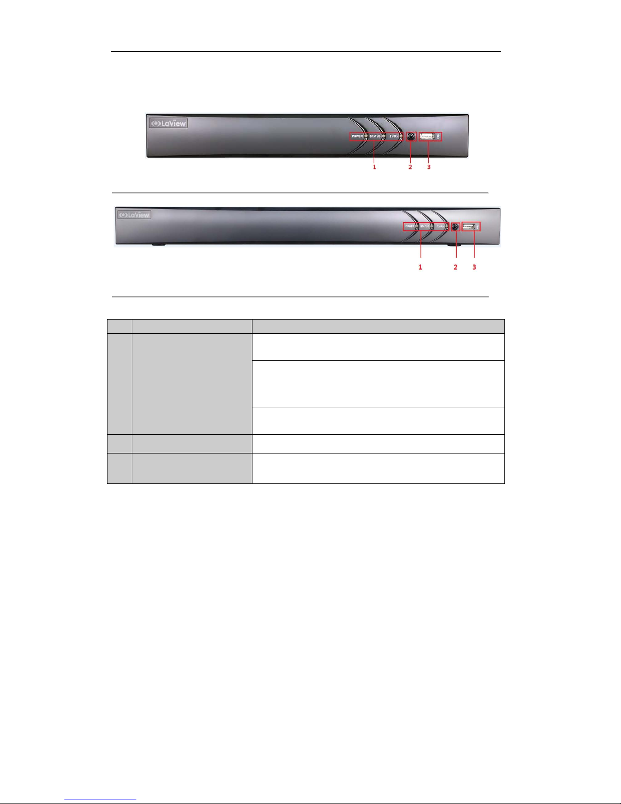
1.1 Front Panels
Figure 1. 1 Front Panel of LV-T9404CF/LV-T9408CF
Figure 1. 2 Front Panel of LV-T9416CF
Table 1. 1 Description of Front Panel
No. Name Function Description
1
Status Indicators
POWER: the POWER indicator turns green when NVR is powered
up.
STATUS: 1.The l ight is green when the IR remote control is enabled;
2.The light is red when the function of the composite keys (SHIFT)
are used; 3. The light is out when none of the above condition is met/
Tx/Rx: TX/RX indicator flickers green when network connection is
functioning normally.
2 IR Receiver Receiver for IR remote.
3 USB Interfaces
Universal Serial Bus (USB) ports for additional devices s uch as USB
mouse and USB Hard Disk Drive (HDD).
Page 15
User Manual of Digital Video Recorder
15
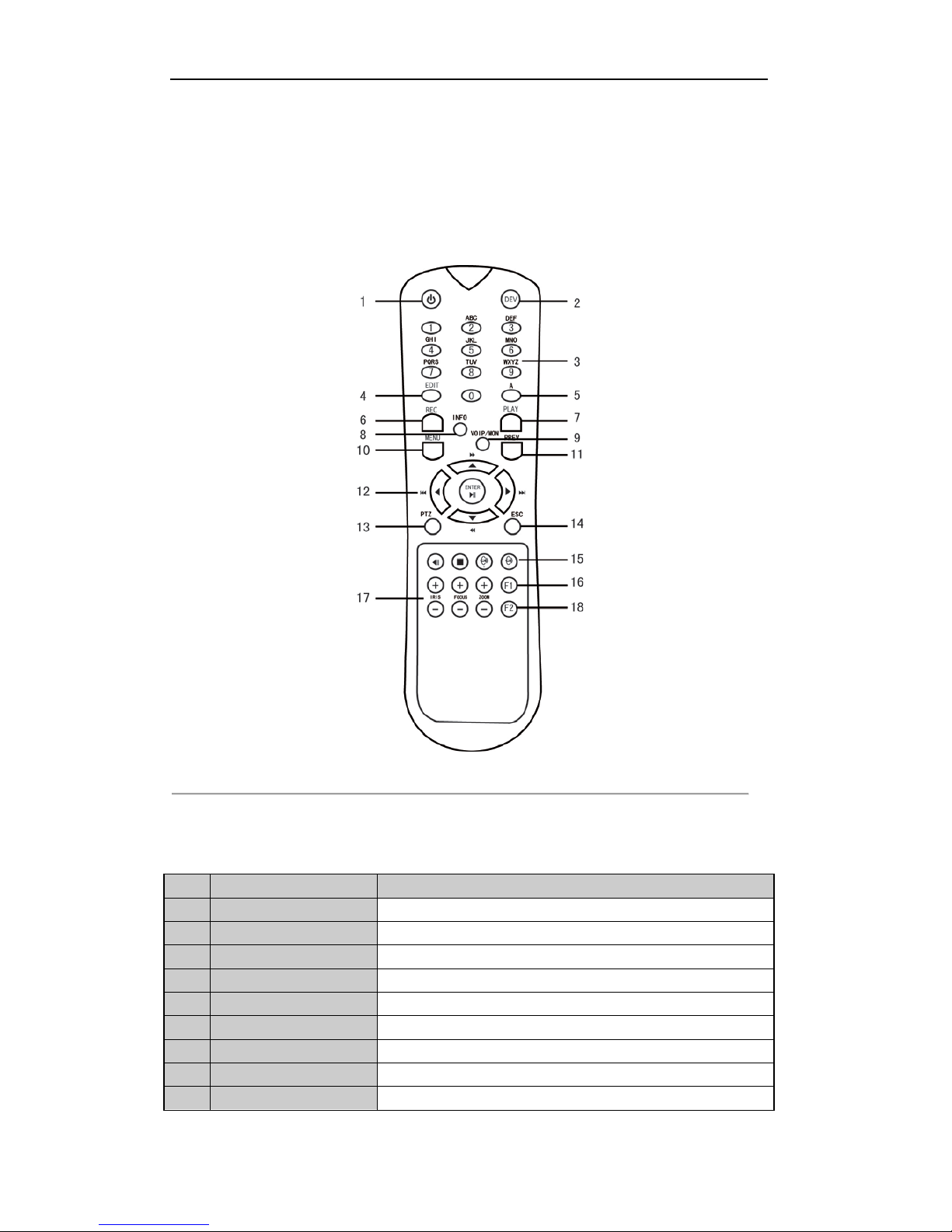
1.2 IR Remote Control Operations
The DVR may also be controlled with the included IR remote control, shown in Figure 1. 7.
Note:
Batteries (2×AAA) must be installed before operation.
Figure 1. 3 Remote Control
The keys on the remote control closely resemble the ones found on the front panel. Refer to Table 1. 6, t hey
include:
Table 1. 2 Description of the IR Remote Control Buttons
No. Name Description
1 POWER
Power on/off the device.
2 DEV
Enables/Disables Remote Control.
3 Alphanumeric Buttons
Same as Alphanumeric buttons on front panel.
4 EDIT Button
Same as EDIT/IRIS+ button on front panel.
5 A Button
Same as A/FOCUS+ button on front panel.
6 REC Button
Same as REC/SHOT button on front panel.
7 PLAY Button
Same as the PLAY/AUTO button on front panel.
8 INFO Button
Same as the ZOOM+ button on front panel.
9 VOIP/MON Button
Same as the MAIN/SPOT/ZOOM- button on front panel.
Page 16

User Manual of Digital Video Recorder
16
No. Name Description
10 MENU Button
Same as the MENU/WIPER button on front panel.
11 PREV Button
Same as the PREV/FOCUS- button on front panel.
12 DIRECTION/ENTER
Buttons
Same as the DIRECTION/ENTER buttons on front panel.
13 PTZ Button
Same as the PTZ/IRIS- button on front panel.
14 ESC Button
Same as the ESC button on front panel.
15 RESERVED
Reserved for future usage.
16 F1 Button
Same as the F1/LIGHT button on front panel.
17 PTZ Control Buttons
Buttons to adjust the iris, focus and zoom of a PTZ camera.
18 F2 Button
Same as the F2/AUX button on front pane l .
Troubleshooting Remot e Control:
Note:
Make sure you have instal l batteries properly in the remote control. And you have to aim the remote
control at the IR receiver in the front panel.
If there is no response after you press any button on the remote, follow the procedure below to troubleshoot.
Steps:
1. Go into Menu > Settings > General > More Sett in gs by operating the front control panel or the mouse.
2. Check and remember DVR ID#. The default ID# is 255. This ID# is valid for all IR remote controls.
3. Press the DEV button on the remote control.
4. Enter the DVR ID# in step 2.
5. Press the ENTER button on the remote.
If the Status indicator on the front panel turns blue, the remote control is operating properly. If the Status
indicator does not turn blue and there is still no response from the remote, please check the following:
1. Batteries are installed correctly and the polarit ies of the batteries are not r evers ed.
2. Batteries are fresh and not out of charge.
3. IR receiver is not obstructed.
If the remote still cannot function properly, please change the remote and try again, or contact the device
provider.
Page 17

User Manual of Digital Video Recorder
17
1.3 USB Mouse Operation
A regular 3-button (Left/Right/Scroll-wheel) USB mouse can also be used with this DVR. To use a USB mouse:
Steps:
1. Plug USB mouse into one of the USB interfaces on the front panel of the DVR.
2. The mouse should automatical ly be detected. If in a r ar e cas e that the mouse is not detected, the possible
reason may be that the two d evi ces are not compatible, please refer to the recommend ed the device list
from your provider.
The operation of the mouse:
Table 1. 3 Description of the Mouse Control
Name Action Description
Left-Click
Single-Click
Live view: Select channel and show the quick set menu.
Menu: Select and enter.
Double-Click
Live view: Switch between single-screen and multi-screen.
Click and Drag
PTZ control: Wheeling.
Privacy mask and motion detection: Select target area.
Digital zoom-in: Drag and select target area.
Live view: Drag channel/time bar.
Right-Click Single-Click
Live view: Show menu.
Menu: Exit current menu to upper level menu.
Scroll-Wheel Scrolling up
Live view: Previous scr een.
Menu: Previous item.
Scrolling down
Live view: Next screen.
Menu: Next item.
Page 18
User Manual of Digital Video Recorder
18
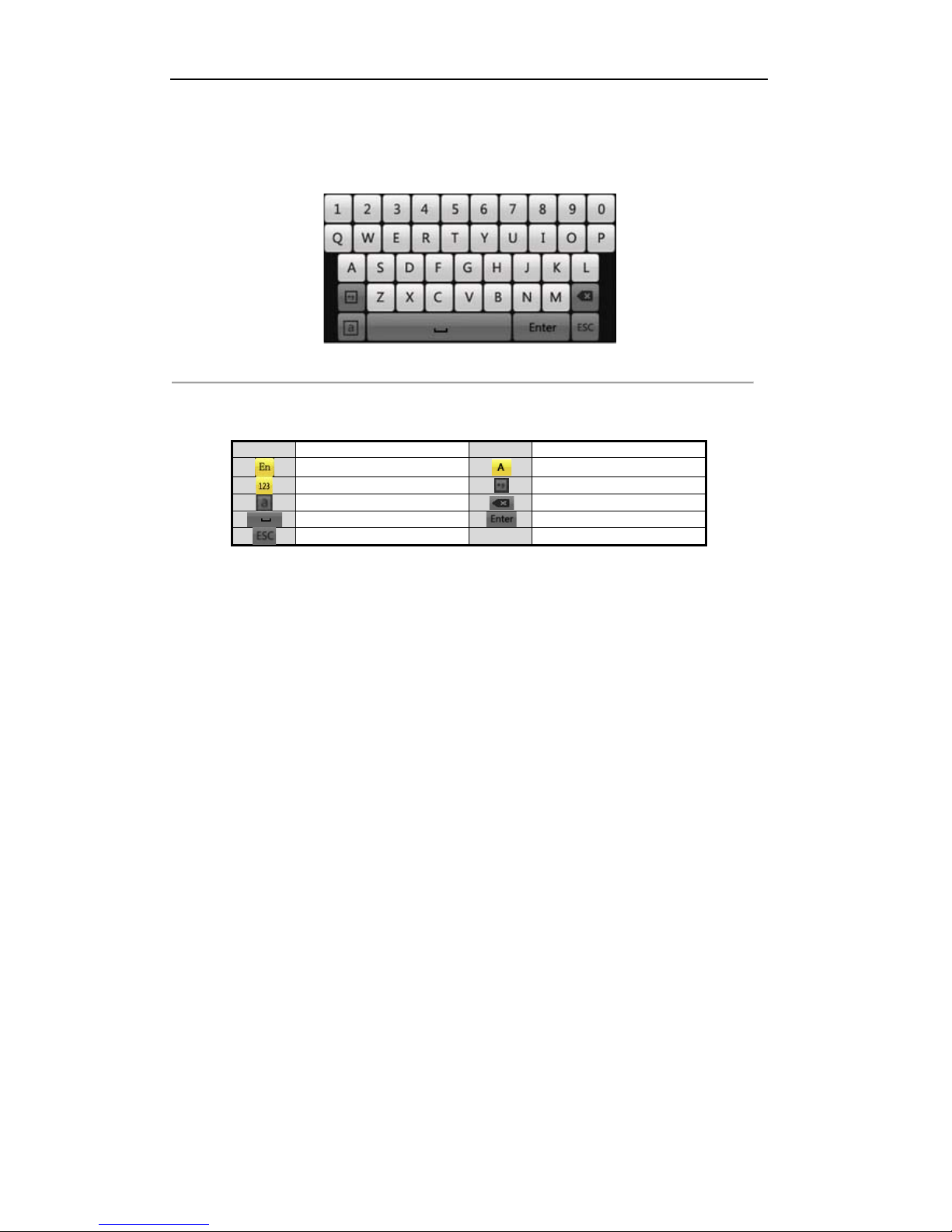
1.4 Input Method Descri ption
Figure 1. 4 Soft Keyboard
Description of the b ut tons on the soft key boa r d:
Table 1. 4 Description of the Soft Keyboard Icons
Icons
Description
Icons
Description
English
Capital English
Numbers
Symbols
Lowercase/Uppercase
Backspace
Space
Enter
Exit
Page 19
User Manual of Digital Video Recorder
19
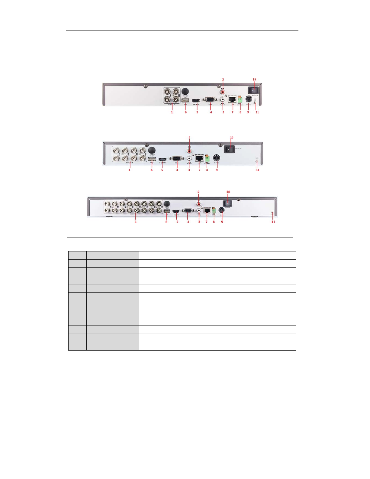
1.5 Rear Panel
Figure 1. 5 LV-T9404CF
Figure 1. 6 LV-T9408CF
Figure 1. 7 LV-T9416CF
Table 1. 5 Description of Front Panel
No. Item Description
1 VIDEO IN BNC interface for TVI and analog video input.
2 AUDIO IN RCA connector
3 AUDIO OUT RCA connector
4 VGA DB15 connector for VGA output. Display local video output and menu.
5 HDMI HDMI video output connector.
6 USB Port Universal Serial Bus (USB) port for additional devices.
7 Network Interface Connector for network
8 RS-485 I nt e r face Connector for RS-485 devices.
9 Powe r S upply DC 12V power supply.
10 Power Switch Switch for turning on/off the device.
11 GND Ground
Page 20

User Manual of Digital Video Recorder
20
Chapter 2 Getting Started
Page 21
User Manual of Digital Video Recorder
21
2.1 Starting Up and Shutting Down the DVR
Purpose:
Proper startup and shutdown procedures are crucial to expanding the life of the DVR.
Before you start:
Check that the voltage of the extra power supply is the same with the DVR’s requirement, and the ground
connection is working properly.
Starting up the DVR
Steps:
1. Check the power supply is plugged into an electrical outlet. It is HIGHLY recommended that an
Uninterruptible Power Supply (UPS) be used in conjunction with the device.
2. Turn on the power switch on the rear panel, and the Power indicator LED should turn on indicating that
the unit begins to start up.
3. After startup, the Power indicator LED remains on.
Shutting down the D VR
Steps:
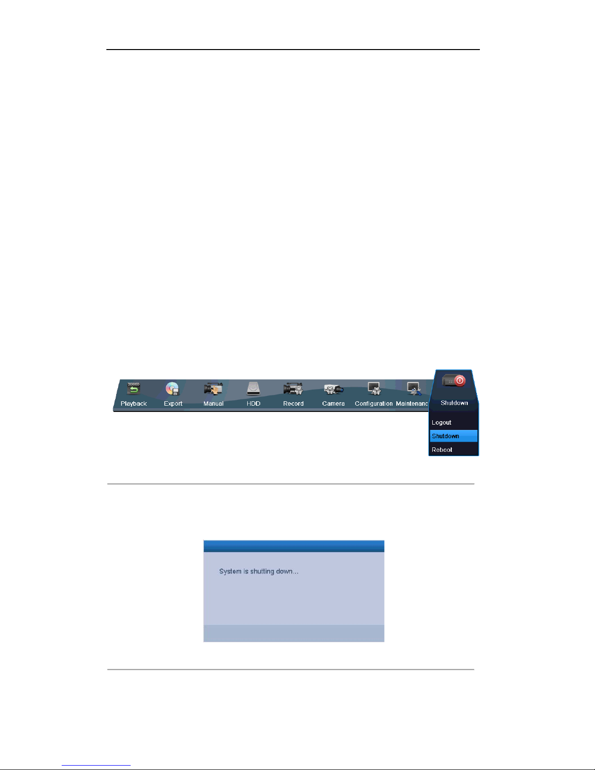
There are two proper ways to shut down the DVR. To shut down the DVR:
OPTION 1: Standard shutdown
1. Enter the Shutdown menu.
Menu > Shutdown
Figure 2. 1 Shutdown Menu
2. Select t he Shutdown button.
3. Click the Yes button.
4. Turn off the power switch on the rear panel when the note appears
Figure 2. 2 Shutdown Tips
OPTION 2: By operating the front panel
1. Pr ess and hold the POWER button on the front panel for 3 seconds.
Page 22

User Manual of Digital Video Recorder
22
2. Enter the administrator’s username and password in the dialog box for authentication.
3. Click the Yes button.
Note:
Do not press the POWER button again when the system is shutting down.
The device remains standby mode after shutting down, and the POWER indicator turns red; you can
turn on the device by pressing the POWER button on the remote control.
Rebooting the DVR
While in the Shutdown menu (Figure 2. 1), you can also reboot the DVR.
Steps:
1. Enter the Shutdown menu by clicking Menu > Shutdown.
2. Click the Logout button to log out or the Reboot button to reboot the DVR.
Page 23
User Manual of Digital Video Recorder
23
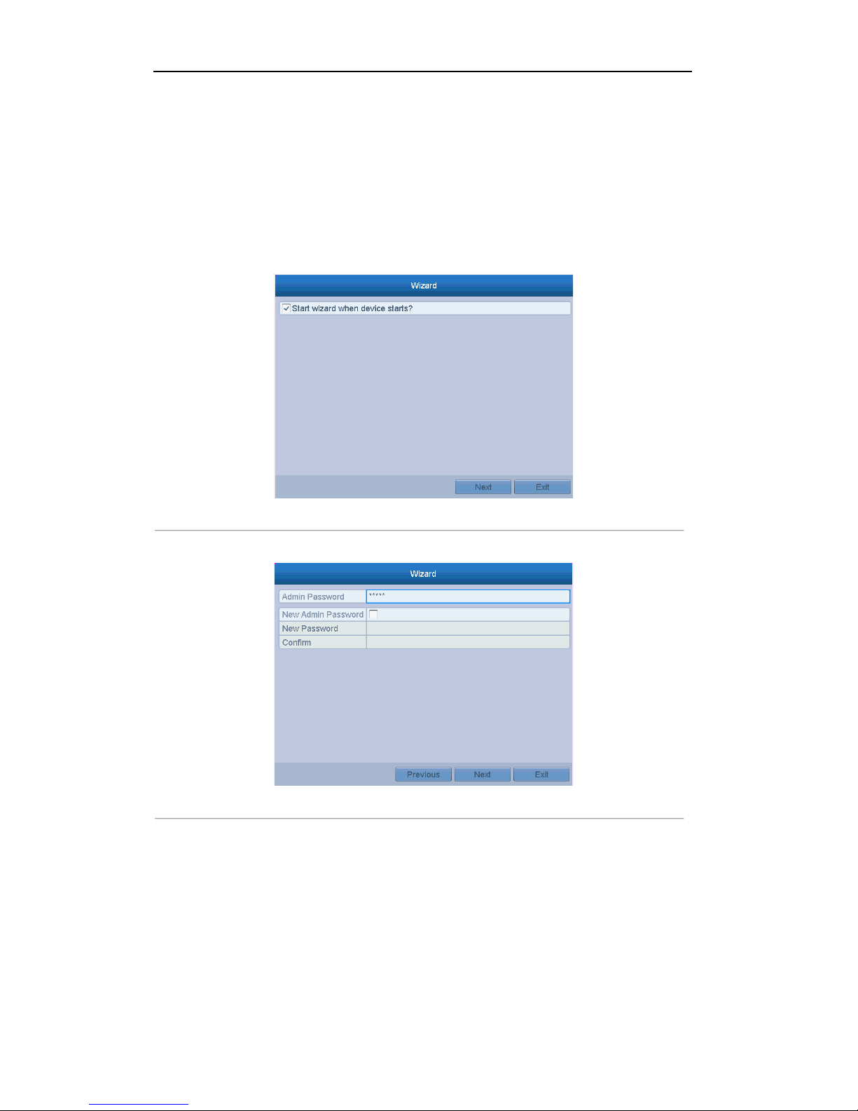
2.2 Using the Wizard for Basic Configuration
By default, the Setup Wizard will start once the DVR has loaded, as shown in Figure 2. 3.
Steps:
1. The Setup Wizard can walk you through some important settings of the DVR. If you do not want to use
the Setup Wizard at this time, click the Cancel button. You can also choose to use the Setup Wizard next
time by leaving the “Start wizard when device starts?” checkbox in checked status.
Figure 2. 3 Start Wizard Interface
2. Click Next button on the Wizard window to enter the Login window, as shown in Figure 2. 4.
Figure 2. 4 Login Window
3. Enter the admin password. By default, the password is 12345.
Note:
You are highly recommended to change the default password right after the first login to avoid safety
problem.
4. To change the admin password, check the New Admin Password checkbox. Enter the new password and
confirm the password in the given fields.
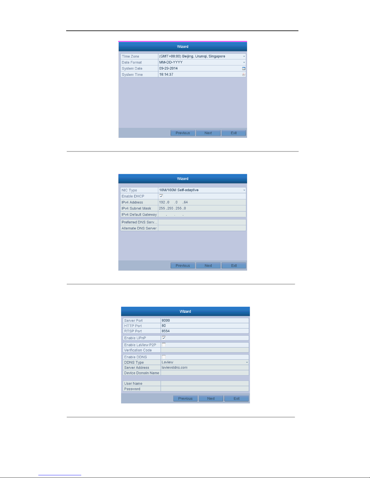
5. Click the Next button to enter th e dat e and time settings window, as shown in Figure 2. 5.
Page 24
User Manual of Digital Video Recorder
24
Figure 2. 5 Date and Time Settings
6. After the time settings, click Next button which will take you back to the General Network Setup Wizard
window, as shown in Fig ur e 2. 6.
Figure 2. 6 General Network Configuration
7. Click Next button after you having con figured the network parameters, which will take you to the
Advanced Network Setup Wizard window, as shown in Figure 2. 7.
Figure 2. 7 Advanced Network Configuration
8. Set t he parameters of port No., ezviz Cloud, Auto UPnP or DDNS if required.
Page 25
User Manual of Digital Video Recorder
25
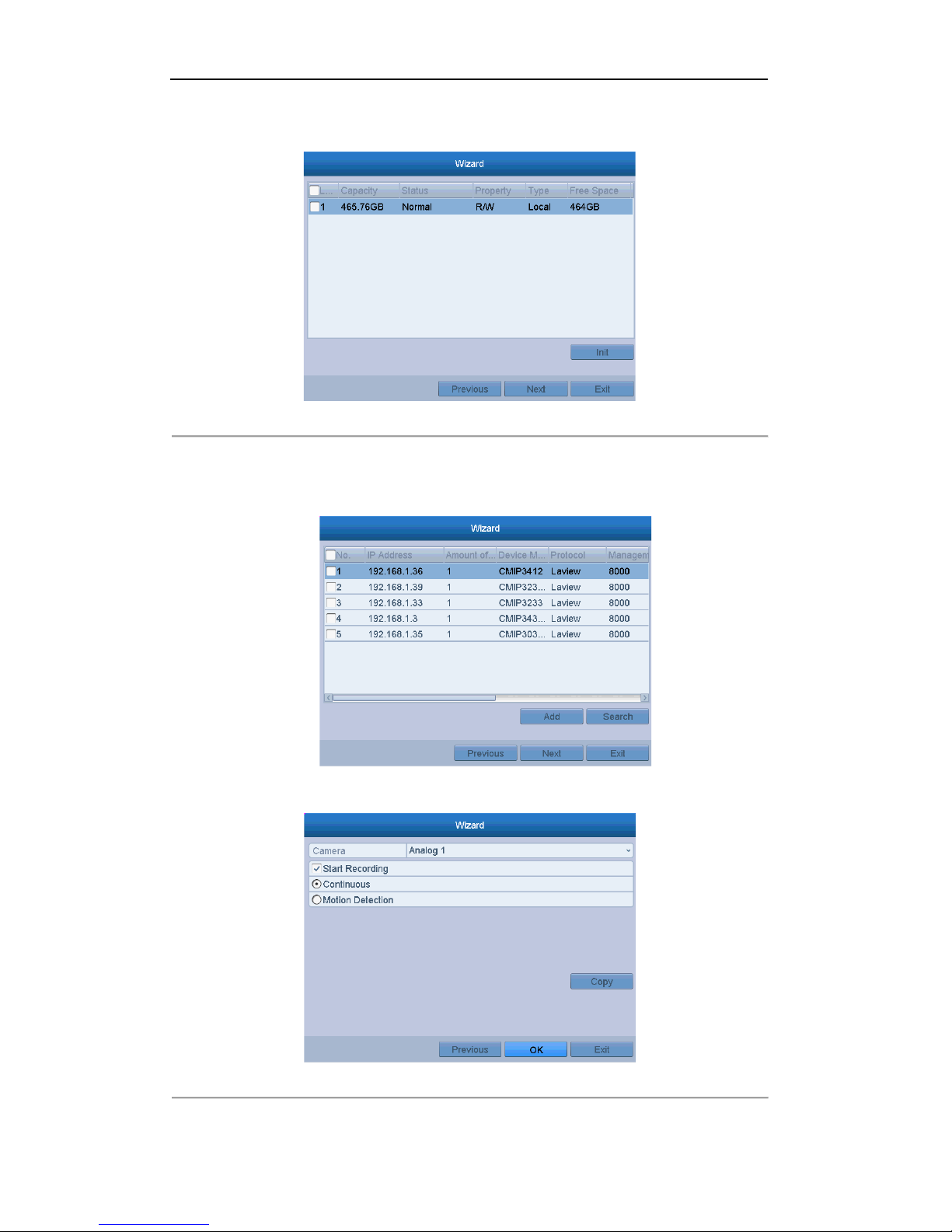
9. Click Next button after configuring the advanced network parameters, which will take you to the HDD
Management window, shown in Figure 2. 8.
Figure 2. 8 HDD Management
10. To initialize the HDD, click the Init button. Initialization will remove all the data saved i n t he HDD.
11. Click Next button. You enter the Adding IP Camera interface.
12. Click Search to find onlin e IP C amera. S elect the IP camera to be added, and click the Add button.
Figure 2. 9 Search for IP camera
13. Click Next button to enter the Record Settings window, as shown in Figur e 2. 10.
Figure 2. 10 Record Settings
Page 26

User Manual of Digital Video Recorder
26
14. Click Copy to copy the recording setting to other cameras.
15. Click OK to save the settings and exit the wizard.
Page 27
User Manual of Digital Video Recorder
27
2.3 Adding and Connecting the IP Cameras
2.3.1 Adding the Online IP Cameras
Purpose:
The main function of the NVR is to connect the network cameras and record the video got from it. So before
you can get a live view or record of the video, you should add the network cameras to the connection list of the
device.
Before you start:
Ensure the network connection is valid and correct. For detailed checking and configuring of the network,
please see Chapter 9.1, 9.3and 9.4.
Note:For the 4-ch device, 1-ch IP camera can be connected; and for other models, up to 2-ch IP cameras can be
connected.
OPTION 1:
Steps:
1. Right-click the mouse when you in the live view mode to show the right-click menu.
Right-click Menu
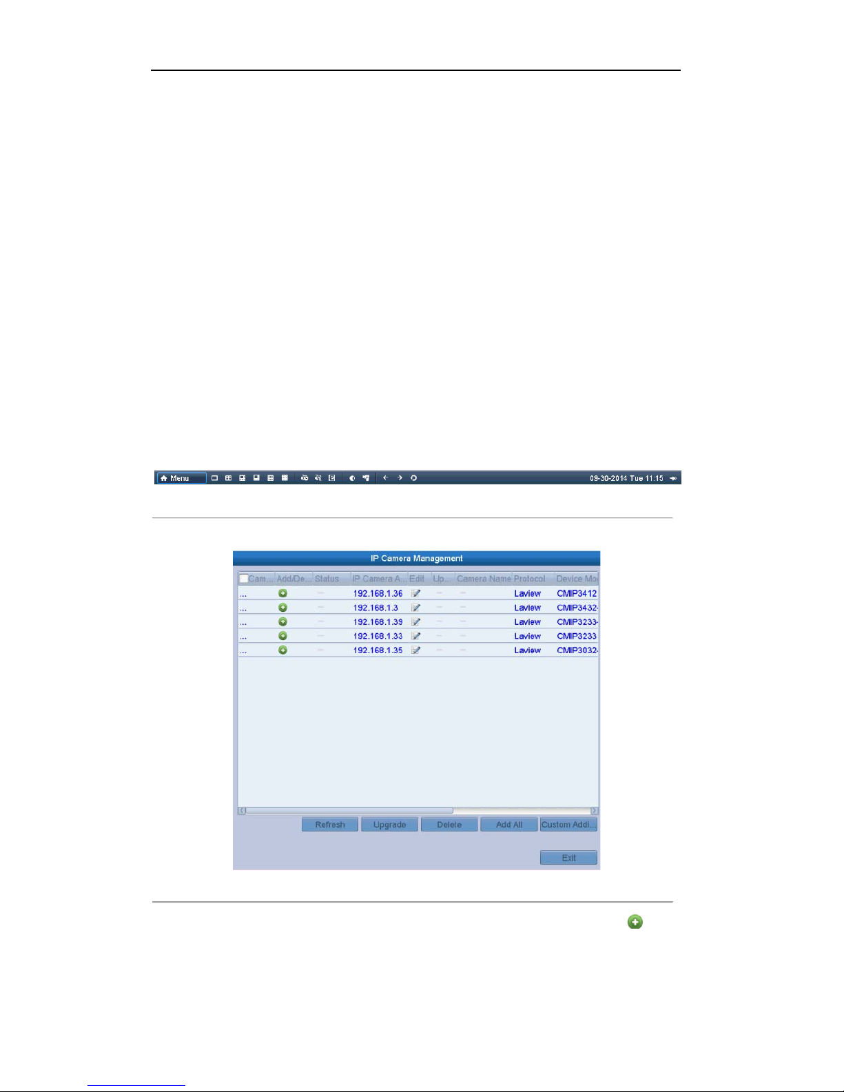
2. Select Add IP Camera in the pop-up menu to enter the IP Camera Management interface.
Figure 2. 11 Adding IP Camera Interface
3. The online cameras with s ame network segment will be d isplayed in the camera list. Click the button
to add the camera.Or you can click the Add All bu tton to add all the detected online IP cameras.
Page 28
User Manual of Digital Video Recorder
28
Table 2. 1 Explanation of the icons
Icon Explanation Icon Explanation
Edit basic parameters of th e camera
Add the detected IP camera.
The camera is connected.
The camera is disconn ected; you can click the
icon to get the exception information of camera.
Delete the IP camera
Advanced settings of th e camer a.
Update the IP camera
4. To add other IP cameras:
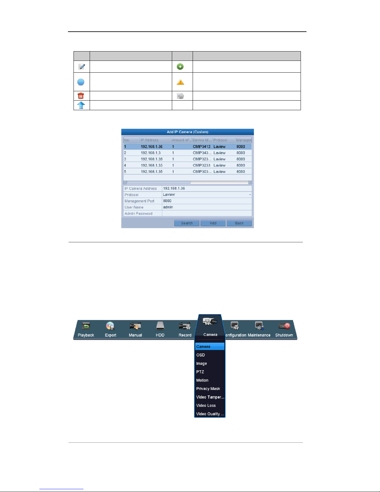
1) Click the Custom Adding button to pop up the Add IP Camera (Custom) interface.
Figure 2. 12 Custom Adding IP Camera Interface
2) You can edit the IP address, protocol, management port, and other information of the IP camera to be
added.
3) Click Add to add the camera.
OPTION 2:
Steps:
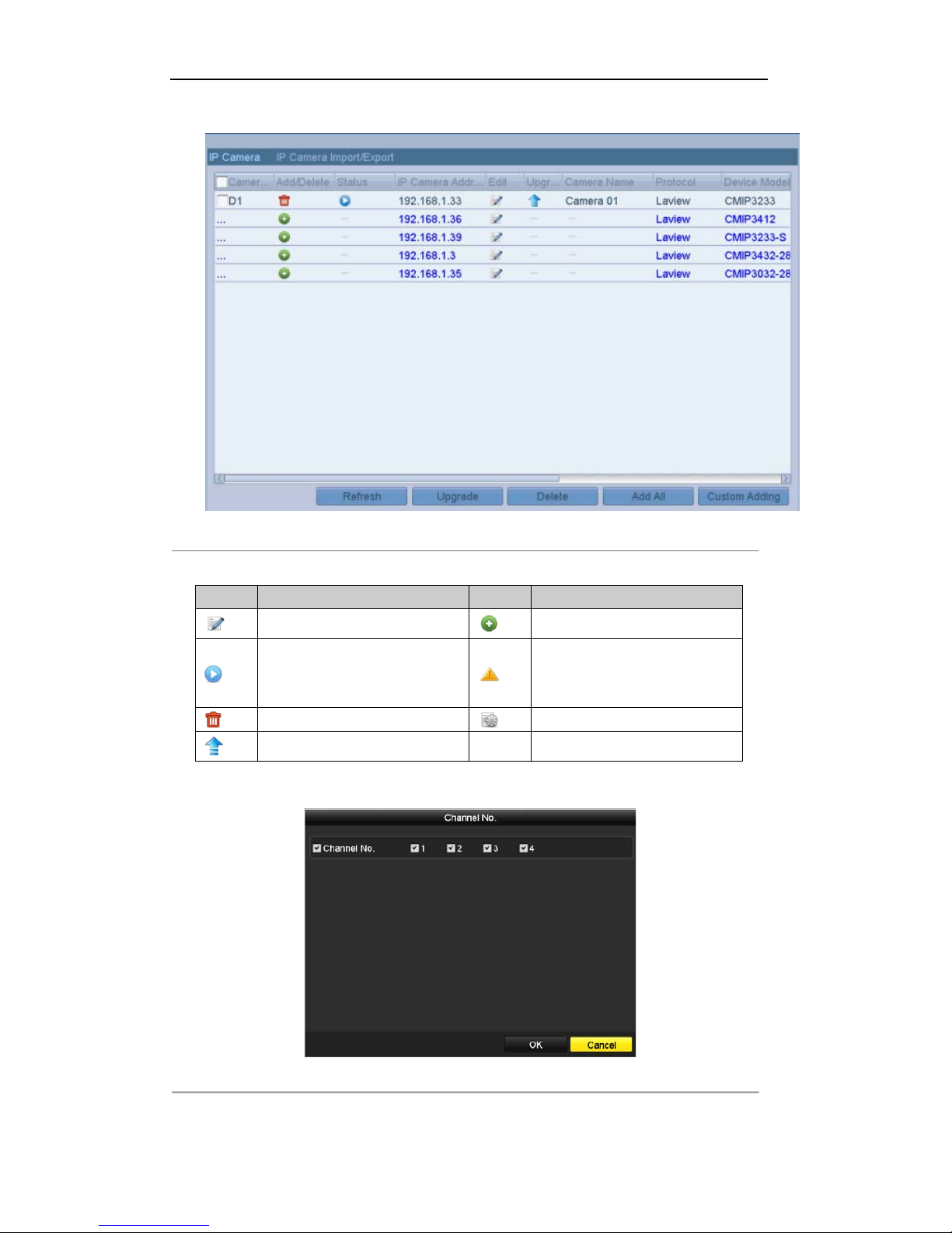
1. Enter the Camera Management interface.
Menu> Camera> Camera
Figure 2. 13 Main Menu
Page 29
User Manual of Digital Video Recorder
29
2. Repeat the step 3 and 4 of OPTION 1 to add the camera.
Figure 2. 14 IP Camera Management Interface
Table 2. 2 Explanation of the icons
Icon Explanation Icon Explanation
Edit basic parameters of th e camera
Add the detected IP camera.
The camera is connected; you can
click the icon to get the live view of
the camera.
The camera is disconnected ; you can
click the icon to get the exception
information of camera.
Delete the IP camera
Advanced settings of th e camer a.
Update the IP camera
3. (For the encoders with multiple channels only) check the checkbox of Channel No. in the pop-up window,
as shown in the following figure, and click OK to finish adding.
Figure 2. 15 Selecting Multiple Channels
Page 30
User Manual of Digital Video Recorder
30
2.3.2 Editing the Connected IP Cameras and Configuring
Customized Protocols
After the adding of the IP cameras, the basic information of the camera lists in the page, you can configure the
basic setting of the IP cameras.
Steps:
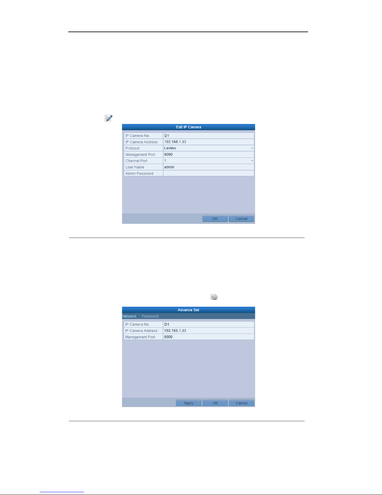
1. Click the icon to edit the parameters; you can edit the IP address, protocol and other parameters.
Figure 2. 16 Edit the Parameters
Channel Port : If the connected device is an encodi ng device with multiple chann els, you can choose the
channel to connect b y selecti ng the channel port No. in the dropdown list.
2. Click OK to save the settings and exit the edit in g i nterface.
To edit advanced parameters:
Steps:
1. Drag the horizontal scroll bar to the right side and click the icon.
Figure 2. 17 Network Configuration of the Camera
2. You can edit the network information and the password of the camera.
Page 31

User Manual of Digital Video Recorder
31
Figure 2. 18 Password Configuration of the Camera
3. Click Apply to save the sett ings and click OK to exit the interface.
Page 32

User Manual of Digital Video Recorder
32
Chapter 3 Live View
Page 33

User Manual of Digital Video Recorder
33
3.1 Introduction of Live View
Live view shows you the video image getting from each camera in r eal time. The DVR will automatically enter
Live View mode when powered on. It is also at the very top of the menu hierarchy, thus hitting the ESC many
times (depending on which menu you’re on) will bring you to the Live View mode.
Live View Icons
In the live view mode, there are icons at the right top of the screen for each channel, showing the status of the
record and alarm in the ch annel, so that you can know whether the channel is recorded, or whether there are
alarms occur as soon as possible.
Table 3. 1 Description of Live View Icons
Icons Description
Alarm (video loss, tampering, motion detection or sensor alarm)
Record (manual record, schedule record, motion d etection or alarm triggered record)
Alarm & Record
Page 34

User Manual of Digital Video Recorder
34
3.2 Operations in Live View Mode
In live view mode, there are many functions provided. The functions are listed below.
• Single Screen: show only one screen on the monitor.
• Multi-screen: show multiple screens on the monitor simultaneously.
• Auto-switch: the s cr een is auto switched to the next one. And you must set the dwell time for each screen
on the configuration menu before enabling the auto-switch. Menu>Configuration>Live View>Dwell
Time.
• Start Recording: normal record and motion detection record are supported.
• Quick Se t: select the output mode to Standard, Bright, Gentle or Vivid.
• Playback: play back the recorded videos for current day.
• Aux/Main output switch: the DVR checks the connection of the output interfaces to define the main and
auxiliary output interfaces. The priority level for the main and aux output is HDMI>VGA>CVBS. This
means if the HDMI is used, it will be the main output. If the HDMI is not used, the VGA output will be
the main output. See the table below.
Table 3. 2 Priorities of Interfaces
HDMI VGA CVBS Main output Auxiliary
output
1
√ √ √
HDMI VGA
2
√ × √
HDMI CVBS
3
× √ √
VGA CVBS
4
× × √
CVBS
√ means the interface is in use, × means the interface is out of use or the connection is invalid. And the
HDMI, VGA and CVBScan be used at the same time.
When the aux output is enabled, the main output cannot do any operation, and you can do some basic operation
on the live view mode for the Aux output.
3.2.1 Using the Mouse in Live View
Table 3. 3 Mouse Operation in Live View
Name Description
Enter the menu of the system by clicking the icon.
Switch to the single full screen.
Adjust the screen layout by clicking the specific icon.
/
Switch to the previous/next screen.
Enable/disable the auto-switch of the screens.
Start continuous recording or motion detection recording of all channels.
Enter the playback interface and start playing back the video of the selected
channel immediately.
Four modes of output supported, including Standard, Bright, Gentle and Vivid.
Fix the menu
Note: The dwell time of the live view configuration must be set before using Start Auto-switch.
Page 35

User Manual of Digital Video Recorder
35
Note: If the corresponding camera supports intelli gent function, the Reboot Intelligence option will be included
when right-clicking mouse on this camera.
Note: If you enter Aux monitor mode and the Aux monitor is not connected, the mouse operation is disabled;
you need to switch back to the Main output with the F1 butt on on f ront pa ne l or VOIP/MON button on IR
remote control and then press the Enter button.
Figure 3. 1 Right-click Menu
3.2.2 Using an Auxiliary Monitor
Certain features of the Live View are also available while i n an Aux monitor. These features include:
• Single Screen: Switch to a full screen display of th e s elected camera. Camera can be selected from a
dropdown list.
• Multi-screen: Switch between different display layout options. Layout options can be selected from a
dropdown list.
• Previous Screen: When displaying less than the maximum number of cameras in Live View, clicking this
feature will switch to the previous set of displays.
• Next Screen: When displaying less than the maximum number of cameras in Live View, clicking this
feature will switch to the next set of displays.
• Quick Se t: Set the video output mode to Standard, Bright, Gentle or Vivid.
• Menu Output Mode: Select the menu output mode to HDMI/VGA, Main CVBS or Auto.
• PTZ Control: The shortcut to enter the PTZ control interface.
• Main Monitor: Enter Main operation mode.
Note: In the live view mode of the main output monitor, the menu operation is not available while Aux output
mode is enabled.
3.2.3 Main/Aux Output Switching
When the HDMI/VGA output is configured as the main output, you can perform the following operation to
switch to CVBS output as the main output.
Steps:
1. Use the mouse wheel to double-click on the HDMI/VGA output screen, and the following message box
pops up:
2. Use the mouse wheel to double-click on the screen again to switch to the Aux output, or clic k Cancel to
cancel the operation .
3. Select the Menu Out put Mode to Main CVBS from the right-click menu on the CVBS output monitor.
4. On the pop-up message box, click Yes to restart the device to enable the CVBS output as the main output.
Note: You can select the Menu Output Mode under Menu>Configuration>More Settings to Auto or
HDMI/VGA and then restart the device to switch the main output back to HDMI/VGA output.
Page 36

User Manual of Digital Video Recorder
36
3.2.4 Quick Setting Toolbar in Live V iew Mode
On the screen of each channel, there i s a quick setting toolbar which shows when you point the mouse to the
bottom of the screen.
Figure 3. 2 Quick Setting Toolbar
Table 3. 4 Description of Quick Setting Toolbar Icons
Icons Description Icons Description Icons Description
Enable/Disable
Manual Record
Instant Playback
Mute/Audio on
PTZ Control
Digital Zoom
Image Settings
Close Live View
Instant Playback only shows the record in last five minutes. If no record is found, it means there is no
record during the last five minutes.
Digital Zoom can zoom in t he selected area to the full screen. Click and draw to select the area to zoom in,
as shown in Figure 3. 4.
Figure 3. 3 Digital Zoom
Image Settings icon can be selected to enter the Image Settings menu.
Four modes are selectable ac cording to the real situation:
• Standard: for general lighting conditions (default).
• Indoor: the image is relatively smoother.
Page 37

User Manual of Digital Video Recorder
37
• Dim Light: the image is smoother than the other two modes.
• Outdoor: the image is relatively clearer and sharper. The degree of contrast and saturation is high.
Figure 3. 4 Image Settings
You can adjust the image parameters, including brightness, contrast, saturation, hue, sharpness and de-noising.
You can also click Default to restore the default settings and click Copy to copy the image settings to other
analog cameras.
Refer to the Chapter 11.3 Configuring Video Parameters for details.
Page 38

User Manual of Digital Video Recorder
38
3.3 Adjusting Live View Settings
Purpose:
Live View settings can be customized according to different needs. You can configure the output interface,
dwell time for screen to be shown, mute or turning on the audio, the screen number for each channel, etc.
Steps:
1. Enter the Live View Settings interface.
Menu> Configuration> Live View
Figure 3. 5 Live View-General
The settings available in this menu include:
• Video Output Interface: Designates the output to configure the settings for. Outputs include
HDMI/VGA and CVBS (depends on the model).
• Live View Mode: Designates the display mode to be used for Live View.
• Dwell Time: The time in seconds to dwell between switching of channels when enabling auto-switch
in Live View.
• Enable Audio Output: Enables/disables audio output for the selected camera in the live view mode.
• Event Output: Designates the output to show event video; if available, you can select a different
video output interface from the Video Output Interface when an event occurs.
• Full Screen Monitoring Dwell Time: The time in seconds to show alarm event screen.
2. Set the camera order.
1) Select View tab.
Figure 3. 6 Live View- Camera Order
Page 39

User Manual of Digital Video Recorder
39
2) Click a window to select it, and t hen double-click a camera name in the camera list you would like to
display. Setting an ‘X’ means the window will not display any camera.
3) You can also click to start live view of all channels in order and click to stop live view of
all channels. Click or to go to the previous or next page.
4) Click the Apply button.
Page 40

User Manual of Digital Video Recorder
40
3.4 Manual Video Quality Diagnostics
Purpose:
The video quality of the analog channels can be diagnosed manually and you can view the diagnostic results
from a list.
Steps:
1. Enter the Manual Video Quality Diagnostics interface.
Menu> Camera>Manual Video Quality Diagnostics
Figure 3. 7 Video Quality Diagnostics
2. Check the checkboxes to select the channels for diagnostics.
3. Check the check box to enable video quality diagnostics. Click Handling, and the message box for arming
pops up. For getting an accurate feedback, it is reco mmended to set the testing sch edule in the daytime
Figure 3. 8 Diagnostics Result
Note:
Connect the camera to the device for the video quality diagnostics.
Three exception types can be diagnosed: Blurred Image, Abnormal Brightness and Color Cast.
Page 41

User Manual of Digital Video Recorder
41
3.5 User Logout
Purpose:
After logging out, the monitor turns to the live view mode and if you want to do some operation, you need to
enter user name and password to log in again.
Steps:
1. Enter the Shutdown menu.
Menu>Shutdown
Figure 3. 9 Shutdown
2. Click Logout.
Note: After you have logged out the system, menu operation on the screen is invalid. It is required a user
name and password to login the system.
Page 42

User Manual of Digital Video Recorder
42
Chapter 4 PTZ Controls
Page 43

User Manual of Digital Video Recorder
43
4.1 Configuring PTZ Settings
Purpose:
Follow the procedure to set the parameters for PTZ. The configuring of the PTZ parameters should be done
before you control the PTZ camera.
Steps:
1. Enter the PTZ Settings interface.
Menu >Camera> PTZ
Figure 4. 1 PTZ Settings
2. Choose the camera for PTZ set ting in the Camera dropdown list.
3. Click the RS-485 Settings button to set the RS-485 parameters.
Figure 4. 2 PTZ- General
4. Enter the parameters of the PTZ camera.
Note: All th e parameters should be exactl y the s ame as the PTZ camera parameters.
5. Click Apply button to save the settings.
Page 44

User Manual of Digital Video Recorder
44
4.2 Setting PTZ Presets, Patrols & Patterns
Before you start:
Please make sure that the presets, patrols and patterns should be supported by PTZ protocols.
4.2.1 Customizing Presets
Purpose:
Follow the steps to set the Preset location which you want the PTZ camera to point to when an event takes
place.
Steps:
1. Enter the PTZ Control interface.
Menu>Camera>PTZ
Figure 4. 3 PTZ Settings
2. Use th e directional button to wheel the camera to the location where you want to set preset; and the zoom
and focus operations can be recorded in the preset as well.
3. Enter the preset No. (1~255) in the preset text field, and click the Set button to link the location to the
preset.
Repeat the steps2-3 to save more presets.
You can click the Clear button to clear the location information of the preset, or click the Clear All button
to clear the location information of all the presets.
4.2.2 Calling Presets
Purpose:
This feature enables the camera to point to a specified p osition such as a window when an even t takes place.
Steps:
Page 45

User Manual of Digital Video Recorder
45
1. Click the button PTZ in the lower-right corner of the PTZ setting interface;
Or press the PTZ button on the front panel or click the PTZ Control icon in the quick setting bar, or
select the PTZ option in the right-click menu to show the PTZ control panel.
2. Choose Camera in the dropdown list.
3. Click the button to show the general settings of the PTZ control.
Figure 4. 4 PTZ Panel - General
4. Click to enter the preset No. in the corresponding text field.
5. Click the Call Preset button to call it.
4.2.3 Customizing Patrols
Purpose:
Patrols can be set to move the PTZ to different key points and have it stay there for a set duration before moving
on to the next key point. The key points are corresponding to the presets. The presets can be set following the
steps above in Customizing Presets.
Steps:
1. Enter the PTZ Control interface.
Menu>Camera>PTZ
Figure 4. 5 PTZ Settings
Page 46

User Manual of Digital Video Recorder
46
2. Select patrol No. in the drop-down list of patrol.
3. Click the Set button to add key points for the patrol.
Figure 4. 6 Key point Configuration
4. Configure key point parameters, such as the key point No., duration of staying for one key point and speed
of patrol. The key point is corresponding to the preset. The Key Point No. determin es the order at which
the PTZ will follow while cycling through the patrol. The Duration refers to the time span to stay at the
corresponding key point. The Speed defines the speed at which the PTZ will move from one key point to
the next.
5. Click the Add button to add the next key point to the patrol, or you can click the OK button to save the
key point to the patrol.
You can delete all the key points by clicking the Clear button for the selected patrol, or click the Clear
All button to delete all the key pints for all patrols.
4.2.4 Calling Patrols
Purpose:
Calling a patrol makes the PTZ to move according the predefined patrol path.
Steps:
1. Click the button PTZ in the lower-right corner of the PTZ setting int erface;
Or press the PTZ button on the front panel or click the PTZ Control icon in the quick setting bar, or
select the PTZ option in the right-click menu to show the PTZ control panel.
2. Click the button to show the general settings of the PTZ control.
Figure 4. 7 PTZ Panel - General
3. Select a patrol in the dropdown list and click the Call Patrol button to call it.
4. You can click the Stop Patrol bu tton to stop calling it.
Page 47

User Manual of Digital Video Recorder
47
4.2.5 Customizing Patterns
Purpose:
Patterns can be set by record ing the movement of the PTZ. You can call the pattern to make the PTZ movement
according to the predefined path.
Steps:
1. Enter the PTZ Control interface.
Menu > Camera > PTZ
Figure 4. 8 PTZ Settings
2. Choose pattern number in the dropdown list.
3. Click the Start button and click corresponding buttons in the control panel to move the PTZ camera, and
click the Stop button to stop it.
The movement of the PTZ is recorded as the pattern.
4.2.6 Calling Patterns
Purpose:
Follow the procedure to move the PTZ camera according to the predefined patterns.
Steps:
1. Click the button PTZ in the lower-right corner of the PTZ setting int erface;
Or press the PTZ button on the front panel or click the PTZ Control icon in the quick setting bar, or
select the PTZ option in the right-click menu to show the PTZ control panel.
2. Click the button to show the general settings of the PTZ control.
Page 48

User Manual of Digital Video Recorder
48
Figure 4. 9 PTZ Panel - General
3. Click the Call Pattern button to call it.
4. Click the Stop Pattern button to stop calling it.
4.2.7 Customizing Linear Scan Limit
Purpose:
The Linear Scan can be enab led to trigger the scan in th e horizantal direction in the predefined range.
Note: This function is supported by some certain models.
Steps:
1. Enter the PTZ Control interface.
Menu > Camera > PTZ
Figure 4. 10 PTZ Settings
2. Use th e directional button to wheel the camera to the location where you want to set the limit, and click
the Left Limit or Right Limit button to link the location to the corresponding limit.
Note: The speed dome starts linear scan from the left limit to the right limit, and you must set the left limit
on the left side of the right limit, as well the angle from the left limit to the right limit should be no more
than 180º.
Page 49

User Manual of Digital Video Recorder
49
4.2.8 Calling Linear Scan
Purpose:
Follow the procedure to call the linear scan in the predefined scan range.
Steps:
1. Click the button PTZ in the lower-right corner of the PTZ setting int erface;
Or press the PTZ button on the front panel or click the PTZ Control icon in the quick setting bar to
enter the PTZ setting menu in live view mode.
2. Click the button to show the one-touch function of the PTZ control.
Figure 4. 11 PTZ Panel - One-touch
3. Click Linear Scan button to start the linear scan and click the Linear Scan button again to stop it.
Yo u can click t he Restore bu tton to clear the defined left limit and right limit data and the dome needs to
reboot to make settings take effect.
4.2.9 One-touch Park
Purpose:
For some certain model of the speed dome, it can be configure d to start a predefined park action (scan, preset,
patrol and etc.) automatically after a period of inactivity (park time).
Steps:
1. Click the button PTZ in the lower-right corner of the PTZ setting interface;
Or press the PTZ button on the front panel or click the PTZ Control icon in the quick setting bar to
enter the PTZ setting menu in live view mode.
2. Click the button to show the one-touch function of the PTZ control.
Page 50

User Manual of Digital Video Recorder
50
Figure 4. 12 PTZ Panel - One-touch
3. There are 3 one-touch park types selectable, click the co r r es ponding button to activate the park action.
Park (Quick Patrol): The dome starts patrol from the predefined preset 1 to preset 32 in order after the
park time. The undefined preset will be skipped.
Park (Patrol 1): The dome starts move according to the predefined patrol 1 path after the park time.
Park (Preset 1): The dome moves to the predefined preset 1 location after the park time.
Note: The park time can only be set through the speed dome configuration interface, by default the value is 5s.
4. Click the button again to inactivate it.
Page 51

User Manual of Digital Video Recorder
51
4.3 PTZ Control Panel
To enter the PTZ control panel, there are two ways supported.
OPTION 1:
In the PTZ settings int er face, cl ick the PTZ button on the lower-right corner which is next to the Back button.
OPTION 2:
In the Live View mode, you can press the PTZ Control button on the front panel or on the remote control, or
choose the PTZ Control icon , or select the PTZ option in the right-click menu.
Click the Configuration button on the control panel, and you can enter the PTZ Set tings interface.
Note: In PTZ control mode, the PTZ panel will be displayed when a mouse is connected with the device. If no
mouse is connected, the icon appears in the lower-left corner of the window, indicating that this camera
is in PTZ control mode.
Figure 4. 13 PTZ Panel
Table 4. 1 Description of the PTZ panel icons
Icon Description Icon Description Icon Description
Direction button and
the auto-cycle button
Zoom+, Focus+,
Iris+
Zoom-, Focus-, Iris-
The speed of the
PTZ movemen t
Light on/off
Wiper on/off
3D-Zoom
Image Centralization
Menu
Switch to the PTZ
control interface
Switch to the
one-touch control
interface
Switch to the general
settings interface
Previous item
Next item
Start pattern / patrol
Stop the patrol /
pattern movement
Exit
Minimize windows
Page 52

User Manual of Digital Video Recorder
52
Chapter 5 Recording Settings
Page 53

User Manual of Digital Video Recorder
53
5.1 Configuring Encoding Parameters
Before you start:
1. Make sure that the HDD has already been installed. If not, please install a HDD and initialize it.
(Menu>HDD>General)
Figure 5. 1 HDD- General
2. Click Advance to check the storage mode of the HDD.
1) Whether the HDD mode is Quota, please set the maxi mum record capacit y. For detailed information,
see Chapter 10.5 Configuring Quota Mode.
2) If the HDD mode is Group, you should set the HDD group. For detailed information, see Chapter 5.8
Configuring HDD Group for Recording.
Figure 5. 2 HDD- Advanced
Steps:
1. Enter the Record settings interface to configu re the encoding parameters:
Menu>Record>Parameters
Figure 5. 3 Record Encoding
Page 54

User Manual of Digital Video Recorder
54
2. Set the encodin g parameters for recording.
1) Select the Record tab to configure.
2) Select a camera number in the camera dropdown list.
You can configure the stream type, the resolution, the video quality an d other parameters on demand
for Main Stream (Continuous) and Main Stream (Event) respectively.
The Input Resol utio n of camera connected will be displayed in the live view for 5 seconds when the
camera is connected, or the DVR is powered on. The input resolution includes the resolution and
frame rate of the camera, e.g. 1 080P25.
3) You can configure the advantage parameters, including pre-record, post-record time, expired time,
redundant record (this option is only available when the HDD mode is Group) and whether you want
to record audio.
• Pre-record: The time you set to record before th e schedul ed time or even t. For exa mple, when an
alarm triggered the recording at 10:00, if you set the pre-record time as 5 seconds, the camera
records it at 9:59:55.
• Post-record: The time you set to r ecord after the event or the scheduled time. For example, when
an alarm triggered the recording ends at 11:00, if you set the post-record time as 5 seconds, it
records till 11:00:05.
• Expired Time: The expired time is the longest time for a record file to be kept in the HDD, if the
deadline is reached , the file will be deleted. You can set the expired time to 0, and then the file will
not be deleted. The actual keeping time for the file should be determined by the capacity of the
HDD.
• Redundant Record: The red undant record is to decide wheth er you want the camera to save t he
record files in the redundant HDD. You must configure the redundant HDD in HDD settings. For
detailed information, see Chapter 5.7 Configuring Redundant Recording.
• Record Audio: Check the checkbox of Record Audio to record the sound, otherwise record the
image without sound.
• Video Stream: Main stream and sub-stream are selectable for recording. When you select
sub-stream, you can record for a longer time with the same storage space.
• Enable 960 Mode: The option is supported by analog cameras. Enabling the 960 mode to enable
the WD1 resolution for the main stream, otherwise, the resolution supports up to 4CIF. And the
option does not supported by TVI cameras, while the WD1 resolution is available all the time.
4) Click Apply to save the settings.
5) You can copy the settings to other channels by clicking Copy, if the setting can also be used for other
cameras.
Note: You can copy the same settings to the cameras with same signal, e.g., the channel No. 1-3
connect to the TVI cameras, and the chann el No.4 connects to an analog camera, and then the settings
of channel No. 1 can be only copied to channel 2 and 3.
Page 55

User Manual of Digital Video Recorder
55
Figure 5. 4 Copy Camera Settings
3. Set encoding parameters for sub-stream.
1) S elect the Sub strea m tab.
Figure 5. 5 Sub-stream Encoding
2) S elect a camera in the camera dropdown list.
3) Configure the parameters.
4) Click Apply to save the settings.
5) (Optional) If the parameters can also be used to other cameras, click Copy to copy the settings to other
channels.
Page 56

User Manual of Digital Video Recorder
56
5.2 Configuring Record Schedule
Purpose:
Set the record schedule, and then the camera will automatically start/st op recording acco rding to the configured
schedule.
Steps:
1. Enter the Record Schedule interface.
Menu> Record> Schedule
Figure 5. 6 Record Schedule
2. Choose the camera you want to configure in the Camera dropdown list.
3. Check the checkbox of Enable Schedule.
4. Configure the record schedule.
Edit the sch edule
1) Click Edit.
2) In the message box, you can choose the day to which you want to set schedule.
3) To schedule an all-day recording, check the checkbox after the All Day item.
Figure 5. 7 Edit Schedule- All Day
4) To arrange other schedule, leave the All Day checkbox blank and set the Start/End time.
Page 57

User Manual of Digital Video Recorder
57
Figure 5. 8 Edit Schedule- Set Time Period
Note: Up to 8 periods can be configured for each day. And the time periods can’t be overlapped each other.
Repeat the above steps 1)-3) to schedule recording for other days in the week. If the schedule can also be set to
other days, click Copy.
Figure 5. 9 Copy Schedule to Other Days
Note: The Holiday option is available when you enable holiday schedule in Holiday settings. See
Chapter 5.6 Configuring Holiday Record.
5) Click OK to save setting and back to upper level menu.
Draw the schedule
1) Click on the color icon to select a record type in the event list on the right-side of the interface.
Figure 5. 10 Draw the Schedule
Descriptions of the color icons are shown in the figure below.
Figure 5. 11 Descriptions of the Color Icons
Page 58

User Manual of Digital Video Recorder
58
2) Click and drag the mouse on the schedule.
3) Click on the other area except for the schedule table to finish and exit the drawing.
You can repeat step 4 to set schedule for other channels. If the settings can also be used to other channels,
click Copy, and then choose the channel to which you want to copy.
Figure 5. 12 Copy Schedule to Other Channels
5. Click Apply in the Record Schedule interface to save the settings.
Page 59

User Manual of Digital Video Recorder
59
5.3 Configuring Mo ti on De te c t ion Record
Purpose:
Follow the steps to set the motion detection parameters. In the live view mode, once a motion detection event
takes place, the DVR can analyze it and do many actions to handle it. Enabling motion detection function can
trigger certain channels to start recording, or trigger full screen monitoring, audio warning, notifying the
surveillance center, sending email and so on.
Steps:
1. Enter the Motion Detection interface.
Menu>Camera>Motion
Figure 5. 13 Motion Detection
2. Configure Motion Detection:
1) Choose camera you want to configure.
2) Check the checkbox after Enable Moti o n Detection.
3) Drag and draw the area for motion detection by mouse. If you want to set the motion detection for all
the area shot by the camera, click Full Screen. To clear the motion detection area, click Clear.
Figure 5. 14 Motion Detection- Mask
4) Click Handling, and the message box for channel information pops up.
Page 60

User Manual of Digital Video Recorder
60
Figure 5. 15 Motion Detection Settings
5) Select the channels which you want the motion detection event to trigger recording.
6) Click Apply to save the settings.
7) Click OK t o back to the upper level menu.
8) Exit the Motion Detection menu.
3. Configure the schedule.
Please refer to the step 4 of Chapter 5.2 Configuring Record Schedule
, while you may choose Motion as
the record type.
Page 61

User Manual of Digital Video Recorder
61
5.4 Manual Record
Purpose:
Follow the steps to set parameters for the manual record. Using manual record, you don’t need to set a schedule
for recording.
Steps:
1. Enter the Manual settings interface.
Menu> Manual
Figure 5. 16 Manual Record
2. Enable manual record.
Click the status icon before camera n umber to change it to .
Or click the status icon of Analog to enable manual record of all channels.
3. Disable manual r ecord.
Click the status icon to change it to .
Or click the status icon of Analog to disable manual record of all ch annels.
Note: After rebooting al l the manual records enabl ed are canceled.
Page 62

User Manual of Digital Video Recorder
62
5.5 Configuring Holiday Record
Purpose:
Follow the steps to configure the record schedule on holiday for that year. You may want to have different plan
for recording on holiday.
Steps:
1. Enter the Record settin g i nterface.
Menu>Record
2. Choose Holiday on the left bar.
Figure 5. 17 Holiday Settings
3. Enable Edit Holiday schedule.
1) Click to enter the Edit interface.
Figure 5. 18 Edit Holiday Settings
2) Check the checkbox of Enable.
3) Select Mode from the dropdown list.
There are three different modes f or the date format to con figure holiday schedule. By Month, By We ek,
and By Month are selectabl e.
Page 63

User Manual of Digital Video Recorder
63
4) Set the s tart and end date.
5) Click Apply to save settings.
6) Click OK to exit the Edit interface.
4. Configure the record schedule.
Please refer to the Chapter 5.2 Configuring Record Schedule, while you may choose Holiday in the
Schedule dropdown list, or you can draw the schedule on the timeline of Holiday. See the two figures
below.
Figure 5. 19 Edit Schedule- Holiday
Figure 5. 20 Draw Schedule- Holiday
Note:Up to 8 periods can be configured for each day. And the time periods cannot be overlapped each other.
In the time table of the channel, both holiday schedule and normal day schedule are displayed.
Repeat the above step 4 to set Holiday schedule for other channel. If the holiday schedule can also be used to
other channels, cli ck Copy and choose the channel you want to apply the settings.
Page 64

User Manual of Digital Video Recorder
64
5.6 Configuring Redundant Rec ordi n g
Purpose:
Enabling redundant recording, which means saving the record files not only in the R/W HDD but also in the
redundant HDD, will effectively enhance the data safety and reliability.
Before you start:
You must set the Storage mode in the HDD advanced settings to Group before you set the HDD property to
Redundant. For detailed information, please refer to Chapter 10.4 Managing HDD Group. There should be at
least another HDD which is in Read/Write status.
Steps:
1. Enter HDD Information interface.
Menu> HDD>General
Figure 5. 21 HDD General
2. Select the HDD and click to enter the Local HDD Settings interface.
1) Set the HDD property to Redundant.
Figure 5. 22 HDD General-Editing
2) Click Apply to save the settings.
3) Click OK to back to the upper level menu.
3. Enter the Record setting interface.
Menu> Record> Encoding
1) Select the Record tab.
Page 65

User Manual of Digital Video Recorder
65
Figure 5. 23 Encoding Parameters
2) Select Camera you want to configur e.
3) Check the checkbox of Redundant Record.
4) Click Apply to save settings.
If the encoding parameters can al so b e u sed to oth er chann els, cli ck Copy and choose the channel you want to
apply the settings.
Page 66

User Manual of Digital Video Recorder
66
5.7 Configuring HDD Group for Recor di ng
Purpose:
You can group the HDDs and save the record files in certain HDD group.
Steps:
1. Enter HDD setting interface.
Menu>HDD>Advanced
Figure 5. 24 HDD General
2. Select Advanced on the left bar.
Check whether the storage mode of the HDD is Group. If not, set it to Group. For detailed information,
please refer to Chapter 10.4 Managing HDD Group.
3. Select General in the left bar.
Click to enter edi ting interface.
4. Configuring HDD group.
1) Choose a group number for the HDD group.
2) Click Apply to save your settings.
3) Click OK to back to the upper level menu.
Repeat the above steps to configure more HDD groups.
5. Choose the Channels which you want to save the record files in the HDD group.
1) Select Advanced on the left bar.
Figure 5. 25 HDD Advanced
2) Choose Group number in the dropdown list of Record on HDD Group
3) Check the channels you want to save in this group.
4) Click Apply to save settings.
Note:After you have configured the HDD groups, you can configure the Recording settings following the
procedure provided in Chapter 5.2-5.7.
Page 67

User Manual of Digital Video Recorder
67
5.8 Files Protection
Purpose:
You can lock the recorded files or set the HDD property to Read-only to protect the record files from being
overwritten.
Protect file by locking the record files
Steps:
1. Enter Playback setting interface.
Menu> Export
Figure 5. 26 Export
2. Select the channels you want to investigate by checking the checkbox to .
3. Configure the record type, file type, start time and end time.
4. Click Search to show the results.
Figure 5. 27 Export- Search Result
5. Protect the record files.
1) Find the record files you want to protect, and then click the icon which will turn to ,
indicating that the file is locked.
Note: The record files of which the recording is still not completed cannot be locked.
2) Click to change it to to unlock the file and the file is not protected.
Page 68

User Manual of Digital Video Recorder
68
Figure 5. 28 Unlocking Attention
Protect file by setting HDD property to Read-only
Before you start:
To edit HDD property, you need to set the storage mode of the HDD to Group. See Chapter 10.4 Managing
HDD Group.
Steps:
1. Enter HDD setting interface.
Menu> HDD
Figure 5. 29 HDD General
2. Click to edit the HDD you want to protect.
Figure 5. 30 HDD General- Editing
3. Set the HDD to Read-only.
4. Click OK to save settings and back to the upper level menu.
Notes:
You cannot save any files in a Read-only HDD. If you want to save files in the HDD, change the
property to R/W.
If there is only one HDD and is set to Read-only, the DVR cannot record any files. Only live view mode
is available.
If you set the HDD to Read-on ly when the DVR is saving files in it, then the file will be saved in next
R/W HDD. If there is only one HDD, the recording will be stopped.
Page 69

User Manual of Digital Video Recorder
69
Chapter 6 Playback
Page 70

User Manual of Digital Video Recorder
70
6.1 Playing Back Record Files
6.1.1 Playing Back by Channel
Purpose:
Play back the recorded vi deo files of a specific channel in the live view mode. Channel switch is supported.
Instant playback by channel:
Choose a channel in live view mode using the mouse and click the button in the quick setting toolbar.
Note: Only record files recorded during the last five minutes on this channel will be played back.
Figure 6. 1 Instant Playback Interface
Playback by channel
Steps:
1. Enter the Playback interface.
Mouse: Right-click a channel in live view mode an d select from the menu, as shown in Figure 6.2.
Figure 6. 2 Right-click Menu under Live View
Front Panel: press PLAY button to play back record files of the channel under single-screen live view mode.
Under multi-screen live view mode, the recorded files of the top-left channel will be played back.
Note: Pressing numerical buttons will switch playback to the corresponding channels during playback process.
2. Playback management.
The toolbar in the bottom part of Playback interface can be used to control playing progress, as shown in
Figure 6. 3.
Page 71

User Manual of Digital Video Recorder
71
Figure 6. 3 Playback Interface
Click the channel(s) if you want to switch playback to another channel or execute simultaneous playback
of multiple channels.
Figure 6. 4 Toolbar of Playback
Table 6. 1 Detailed Explanation of Playback Toolbar
Button Operation Button Operation Button Operation
/
Audio on/ Mute
/
Start/Stop clipping
Save clip(s)
Add default tag
Add customized tag
Tag management
Digital Zoom
/
Pause / Reverse play/
Single-frame reverse
play
Stop
/
Pause play/ Play/
Single-frame play
30s reverse
30s forward
Speed down
Speed up
Previous da y
Next day
/
Scaling up/down the
time line
Full Screen
Exit
Video t ype
Process bar
Video t ype bar
Note: The indicates the start time and end time of th e r ecord files.
Represents normal recording (man ual or schedule); represent s event recording (motion, alarm,
motion | alarm, motion & alarm).
Playback progress bar: use the mouse to click any point of the progress bar to locate special frames.
Page 72

User Manual of Digital Video Recorder
72
6.1.2 Playing Back by Time
Purpose:
Play back video files record ed in specified time duration. Multi-channel simul ta ne ous pl a yback and channel
switch are supported.
Steps:
1. Enter playback in terface.
Menu>Playback
2. Check the checkbox of channel(s) in the channel list and then double-click to select a date on the
calendar.
Figure 6. 5 Playback Calendar
Note: If there are record fil es fo r that camera in that day, in the calendar, the icon for that day is displayed as
. Otherwise it is displayed as
In the Playback interface:
The toolbar in the bottom part of Playback interface can be used to control playing process, as shown in
Figure 6. 6.
Figure 6. 6 Interface of Playback by Time
Page 73

User Manual of Digital Video Recorder
73
Figure 6. 7 Toolbar of Playback by Time
Table 6. 2 Detailed Explanation of Playback Toolbar
Button Operation Button Operation Button Operation
/
Audio on/ Mute
/
Start/Stop clipping
Save clip(s)
Add default tag
Add customized tag
Tag management
Digital Zoom
/
Pause / Reverse play/
Single-frame reverse
play
Stop
/
Pause play/ Play/
Single-frame play
30s reverse
30s forward
Speed down
Speed up
Previous da y
Next day
/
Scaling up/down the
time line
Full Screen
Exit
Video t ype
Process bar
Video t ype bar
Note:
The indicates the start time and end time of the record files.
represen ts normal recording (manual or schedule); repr esents event recording (motion, alarm,
motion | alarm, motion & alarm).
Playback progress bar: use the mouse to click any point of the progress bar to locate special frames.
6.1.3 Playing Back by Event Search
Purpose:
Play back recording files on one or several channels searched out by restricting event type (e.g. alarm input and
motion detection).
Steps:
1. Enter the Playback interface.
Menu > Playback
2. Select the Event in the drop-down list on the top-left side.
3. Select Alarm Input or Motion as the event type, edit the Start time and End time.
Note: Here we take the playbac k by motion as the example.
Page 74

User Manual of Digital Video Recorder
74
Figure 6. 8 Motion Search Interface
4. Click Search button to get the search result information. You may refer to the right-side bar for the
result.
Figure 6. 9 Search Result Bar(Alarm In and Motion)
5. Click button to play back the file.
You can click the Back bu tton to back to the search interface.
Note: Pre-play and post-play can be configured.
6. (Optional) If multiple channels are triggered recording by the alarm input, clicking the button will
pop up a synchoronouse playback channel selection window. Select channel(s) you want to play and click
the OK button.
7. Playback management.
The toolbar in the bottom part of Playback interface can be used to control playing process.
Page 75

User Manual of Digital Video Recorder
75
Figure 6. 10 Interface of Playback by Event
Figure 6. 11 Toolbar of Playback by Event
Table 6. 3 Detailed Explanation of Playback-by-event Toolbar
Button Operation Button Operation Button Operation
/
Audio on/ Mute
/
Start/Stop clipping
Save clip(s)
Add default tag
Add customized tag
Tag management
Digital Zoom
/
Pause / Reverse play/
Single-frame reverse
play
Stop
/
Pause play/ Play/
Single-frame play
30s reverse
30s forward
Speed down
Speed up
Previous da y
Next day
/
Scaling up/down the
time line
Full Screen
Exit
Video t ype
Process bar
Video t ype bar
Notes:
represen ts normal recording (manual or schedule); repr esents event recording (motion, alarm,
motion | alarm, motion & alarm).
Playback progress bar: use the mouse to click any point of the progress bar to locate speci al frames.
Page 76

User Manual of Digital Video Recorder
76
6.1.4 Playing Back by Tag
Purpose:
Video tag allows you to record related information like people and location of a certain time point during
playback. You are also allowed to use video tag(s) to search for record files and position time point.
Before playing bac k by tag:
1. Enter Playback interface.
Menu>Playback
2. Search and play back the record file(s). Refer to Chapter 6.1.1 Playing Back by Channel for the detailed
information about searching and playback of the record files.
Figure 6. 12 Interface of Playback by Time
Click button to add default tag.
Click button to add customized tag and input tag name.
Note: Max. 64 tags can be added to a single video file.
3. Tag management.
Click button to check, edi t and delete tag(s).
Figure 6. 13 Tag Management Interface
Page 77

User Manual of Digital Video Recorder
77
Steps:
1. Sel ect the Tag from the drop-down list in the Playback interface.
2. Choose channels, edit start time and end time, and then click Search to enter Search Result interface.
Note: You can enter keyword in the textbox to search the tag on your command.
Figure 6. 14 Video Search by Tag
3. Click button to play back the file.
You can click the Back bu tton to back to the search interface.
Note: Pre-play and post-play can be configured.
Figure 6. 15 Interface of Playback by Tag
Page 78

User Manual of Digital Video Recorder
78
Figure 6. 16 Toolbar of Playback by Tag
Table 6. 4 Detailed Explanation of Playback-by-tag Toolbar
Button Operation Button Operation Button Operation
/
Audio on/ Mute
/
Start/Stop clipping
Save clip(s)
Add default tag
Add customized tag
Tag management
Digital Zoom
/
Pause / Reverse play/
Single-frame reverse
play
Stop
/
Pause play/ Play/
Single-frame play
30s reverse
30s forward
Speed down
Speed up
Previous da y
Next day
/
Scaling up/down the
time line
Full Screen
Exit
Video t ype
Process bar
Video t ype bar
Note: represents normal recording (manual or schedule); represents even t recording (motion, al arm,
motion | alarm, motion & alarm).
Playback progress bar: use the mouse to click any point of the progress bar to locate sp ecial frames.
6.1.5 Smart Playback
Purpose:
The smart playback function provides an easy way to get through the less effective information. When you
select the smart playback mode, the system will analyze the video with motion, mark it with green color and
play it in the normal speed while the video without motion will be played in the 8-time speed.
Steps:
1. Enter Playback interface. Menu>Playback
2. Select the Smart in the drop-down list on the top-left side.
3. Select a date in th e calendar and select a camera in the camera list.
4. Click the button to play.
Page 79

User Manual of Digital Video Recorder
79
Figure 6. 17 Smart Playback Interface
Table 6. 5 Detailed Explanation of Smart Playback Toolbar
Button Operation Button Operation Button Operation
Smart Search
Stop
/
Pause play/
Play
Smart search
result
Process bar
/
Scaling
up/down the
time line
Video t ype
Note:
represen ts normal recording (manual or schedule); repr esents event recording (motion, alarm,
motion | alarm, motion & alarm); and represents the video with motion.
Playback progress bar: u se the mouse to cli ck any point of th e progress bar to lo cate special frames, an d
a thumbnail of the specified frame will be displayed.
6.1.6 Playing Back by System Logs
Purpose:
Play back record file(s) associated with channels after searching system logs.
Steps:
1. Enter Log Information interface.
Menu>Maintenance>Log Information
Page 80

User Manual of Digital Video Recorder
80
Figure 6. 18 System Log Search Interface
2. Click Log Search tab to enter Playback by Syst em Logs.
Set search time and type and click Search button.
Figure 6. 19 Result of System Log Search
3. Choose a log with record file and click button to enter Playback interface.
Note: If there is no record file at the time point of the log, the message box “No result found” will pop up.
4. Playback management.
The toolbar in the bottom part of Playback interface can be used to control playing process.
Figure 6. 20 Interface of Playback by Log
Page 81

User Manual of Digital Video Recorder
81
6.1.7 Playing Back External File
Purpose:
Perform the following steps to look up and play back files in the external devices.
Steps:
1. Enter Tag Search interface.
Menu>Playback
2. Sel ect the External File in the drop-down list on the top-left side.
The files are listed in the right-side list.
You can click the button to refresh the file list.
3. Sel ect and click the button to play back it.
Figure 6. 21 Interface of External File Playback
Page 82

User Manual of Digital Video Recorder
82
6.2 Auxiliary Functions of Playback
6.2.1 Playing Back Frame by Frame
Purpose:
Play video files frame by fra me, in order to check image details of the video when abnormal events happen.
Steps:
• Using a Mouse
Go to Playback interface an d click button and until the speed changes to Single frame. One click
on the playback screen rep r es ents playback or adverse pl ayback of one frame. It is also feasible to use
button in toolbar.
• Using the front panel (Not supported with FT series )
Press the button to set the speed to Single frame. One click on the playback screen or press
button on the front panel represents playback or adverse playback of one frame.
6.2.2 Smart Search
Purpose:
In order to locate motion detection event easily and accurately in the playback progress bar, you are allowed to
analyze a certain area (scene) dynamically, and to get all of the related motion detection events that occurred in
this area.
Steps:
1. Go to Smart Playback interface and play the video.
Figure 6. 22 Interface of Playback by Smart
Page 83

User Manual of Digital Video Recorder
83
2. Click the button to go to analysis area selection interface.
3. Click and drag the mouse to draw area(s). You can click button to set th e fu ll screen as target
searching area. After drawing area(s), press button to execute smart search in this area.
Note:
Multi-area and full-screen searching modes are supported.
Figure 6. 23 Draw Area of Smart Search
The results of smart search will be marked as in the progress bar.
Figure 6. 24 Smart Search Result with Video List
Figure 6. 25 Toolbar of Smart Search Playback
Note:
represen ts normal recording (manual or schedule); repr esents event recording (motion, alarm,
motion | alarm, motion & alarm).
Playback progress bar: use the mouse to click any point of the progress bar to locate speci al frames.
Page 84

User Manual of Digital Video Recorder
84
6.2.3 Digital Zoom
Steps:
1. Click the button on the playback control bar to enter Digital Zoom interface.
2. Use the mouse to draw a red rectangle and the image within it will be enlarged u p to 16 times.
Figure 6. 26 Draw Area for Digital Zoom
3. Right-click the image to exit the digital zoom interface.
6.2.4 Reverse Playback of Multi-channel
Purpose:
You can play back record files of multi-channel reversely. Up to 16-ch (with 1920*1080 resolution)
simultaneous reverse playback is supported.
Steps:
1. Enter Playback interface.
Menu>Playback
2. Ch eck more than one checkboxes t o select multiple channels and click to select a date on the calendar.
Page 85

User Manual of Digital Video Recorder
85
Figure 6. 27 4-ch Synchronous Playback Interface
3. Click to play back the r ecord files reversely.
Page 86

User Manual of Digital Video Recorder
86
Chapter 7 Backup
Page 87

User Manual of Digital Video Recorder
87
7.1 Backing up Record Files
Before you start:
7.1.1 Quick Export
Purpose:
Export record files to backup device(s) quickly.
Steps:
1. Enter Video Export interface.
Menu>Export>Normal
Choose the channel(s) you want to back up and click .
Note: The time duration of record files on a specified channel cannot exceed one day. Otherwise, the
message box “Max. 24 hours are allowed for quick export.” will pop up.
Figure 7. 1 Quick Export Interface
2. Export.
Go to Export interface, choose backup device and click to start exporting.
Note: Here we use USB Flash Dr ive and please refer to Chapter 7.1.2 Backing up by Normal Video
Search for more backup devices supported by the device.
Figure 7. 2 Quick Export using USB1-1
Page 88

User Manual of Digital Video Recorder
88
Stay in the Exporting interface until all record files are exported.
Figure 7. 3 Export Finished
3. Check backup result.
Choose the record file in Export interface and click button to check it.
Note: The Player player.exe will be exported auto matical ly during record file export.
Figure 7. 4 Checkup of Quick Export Result Using USB1-1
7.1.2 Backing up by Normal Video Search
Purpose:
The record files can be backu p to various devices, such as USB devices (USB flash drives, USB HDDs, USB
writer) and DVD-R/W.
Backup using USB flash drives, U SB HDDs, USB writer and DVD-R/W
Steps:
1. Enter Export interface.
Menu>Export>Normal
2. Set search condition and click to enter the search result interface.
Notes:
1) Six different Record types are selectable: Continuous, Motion, Alarm, Motion | Alarm, Motion &
Page 89

User Manual of Digital Video Recorder
89
Alarm, Command Triggered and Manual. The command triggered record is configured by the
platform when the device accessed via the platform.
2) Two different File types are selectable: Unlocked and Locked.
Figure 7. 5 Normal Video Search for Backup
3. Select record files you want to back up.
Click button to play the record file if you want to check it.
Check the checkbox before the record files you want to back up.
Note: The size of the currently selected files is displayed in the lower-left corner of the window.
Figure 7. 6 Result of Normal Video Search for Backup
4. Export.
Click and start backup.
Note: If the inserted devi ce is not recognized:
• Click .
• Reconnect device.
• Check for compatibility from vendor.
You can also format USB flash drives or USB HDDs via the d evi ce. USB writer and DVD-R/W cannot
be formatted.
Page 90

User Manual of Digital Video Recorder
90
Figure 7. 7 Export by Normal Video Search using USB Flash Drive
Figure 7. 8 Export by Normal Video Search using USB Writer
Stay in the Exporting interface until all record files are exported with pop-up message box “Export finished”.
Figure 7. 9 Export Finished
5. Check backup result.
Choose the record file in Export interface and click button to check it.
Page 91

User Manual of Digital Video Recorder
91
Note: The Player player.exe will be exported automatically during record file export.
Figure 7. 10 Checkup of Export Result using USB Flash Drive
Figure 7. 11 Checkup of Export Result using USB Writer
7.1.3 Backing up by Event Search
Purpose:
Back up event-related record files using USB devices (USB flash drives, USB HDDs, USB writer), or
DVD-R/W. Quick Backup and Normal Backup are supported.
Steps:
1. Enter Export interface.
Menu>Export>Event
1) Select Alarm Input/Motion from the dropdown list of Event Type.
Note: Here we take Alarm Input as an example.
2) Select the alarm input No. and time.
Page 92

User Manual of Digital Video Recorder
92
3) Click to enter the Search Result interface.
Figure 7. 12 Event Search for Backup
2. Select record files to exp ort.
1) Select an alarm input in the list and click to enter Export interface.
2) Clicking will take you to the interface with d etailed information of all channels
triggered by the selected al arm input. You can view detailed information of the record file, e.g. start time,
end time and file size.
Note: The size of the currently selected files is disp layed in the lower-left corner of the window.
Figure 7. 13 Event Details Interface
3. Export.
Click and start backup.
Note: If the inserted U SB device is not recognized:
• Click .
• Reconnect device.
• Check for compatibility from vendor.
You can also format USB flash drive or USB HDDs via the d evi ce.
Page 93

User Manual of Digital Video Recorder
93
Figure 7. 14 Export by Event Using USB Flash Drive
Stay in the Exporting interface until all record files are exported with pop-up message “Export finished”.
Figure 7. 15 Export Finished
4. Check backup result.
Note: The Player player.exe will be exported auto matical ly during record file export.
Figure 7. 16 Checkup of Event Export Result Using USB Flash Drive
Page 94

User Manual of Digital Video Recorder
94
7.1.4 Backing up Video Clips
Purpose:
You may also select video clips to export directly during Playback, using USB devices (USB flash drives, USB
HDDs, USB writer), or DVD-R/W.
Steps:
1. Enter Playback interface and play back the record file you want to set video clips.
Please refer to Chapter 6.1 Playing Back Record Fil es .
2. During playback, use buttons and in the playback toolbar to start or stop clipping record
file(s).
3. Quit Playback interface after finishing clipping and you will then be prompted to save the clips.
Note: A maximum of 30 clips can be selected for each channel.
Figure 7. 17 Interface of Playback by Time
4. Click Yes to save video clips and enter Export interface, or click No to quit and do not export video
clips.
Figure 7. 18 Video Clip Saving
5. Export.
Click and start backup.
Note: If the inserted U SB device is not recognized:
• Click .
• Reconnect device.
• Check for compatibility from vendor.
Page 95

User Manual of Digital Video Recorder
95
You can also format USB flash drive or USB HDDs via the d evi ce.
Figure 7. 19 Export Video Clips Using USB Flash Drive
Stay in the Exporting interface until all record files are exported with pop-up message “Export finished”.
Figure 7. 20 Export Finished
6. Check backup result.
Note: The Player player.exe will be exported auto matical ly during record file export.
Figure 7. 21 Checkup of Video Clips Export Result Using USB Flash Drive
Page 96

User Manual of Digital Video Recorder
96
7.2 Managing Backup Devices
Management of USB flash dr ive, USB HDD and eSATA HDD.
Note: The eSATA HDD is supported by 7300 and 8100 models only.
1. Enter Search Result interface of record files.
Menu>Export>Normal
Set search condition and click Search button to enter Search Result interface.
Note: At least one chan nel shall be selected.
Figure 7. 22 Normal Video Search
2. Select record files you want to back up.
Click Export button to enter Export interface.
Note: At least one record file shall be sel ected.
Figure 7. 23 Result of Normal Video Search for Backup
3. Backup device management.
Click New Folder button if you want to create a new folder in the backup device.
Select a record file or folder in the backup device and click button if you want to delete it.
Select a record file in the backup device and click but ton to play it.
Click Format button to format the backup device.
Note: If the inserted U SB device is not recognized:
• Click the Refresh button.
• Reconnect device.
Page 97

User Manual of Digital Video Recorder
97
• Check for compatibility from vendor.
Figure 7. 24 USB Flash Drive Management
Management of USB writers and DVD-R/W
1. Enter Search Result interface of record files.
Menu>Export>Normal
Set search condition and click Search button to enter Search Result interface.
Note: At least one channel shall be selected.
Figure 7. 25 Normal Video Search for Backup
2. Select record files you want to back up.
Click Export button to enter Export interface.
Note: At least one record file shall be selected.
Page 98

User Manual of Digital Video Recorder
98
Figure 7. 26 Result of Normal Video Search for Backup
3. Backup device management.
Click Erase button if you want to erase the files from a re-writable CD/DVD.
Note: There must be a re-writable CD/DVD when you make this operation.
Note: If the inserted USB writer or SATA writer is not recognized:
• Click the Refresh button.
• Reconnect device.
• Check for compatibility from vendor.
Figure 7. 27 USB Writer Management
Page 99

User Manual of Digital Video Recorder
99
Chapter 8 Alarm Settings
Page 100

User Manual of Digital Video Recorder
100
8.1 Setting Motion Dete c tion
Steps:
1. Enter Motion Detection interface of Ca mera Management and choose a camera you want to set up
motion detection.
Menu> Camera> Motion
Figure 8. 1 Motion Detection Setup Interface
2. Set detection area and sensitivity.
Check checkbox to enable motion detection, use the mouse to draw detectio n area(s) and drag the
sensitivity bar to set sensitivity.
Click to set alarm response actions.
Figure 8. 2 Set Detection Area and Sensitivity
3. Click Trigger Channel tab and select one or more channels which will s tart to record or become
full-screen monitoring when motion alarm is triggered.
 Loading...