

Page 1
HighPoint Technologies, Inc.
Address: 1161 Cadillac Court, Milpitas, CA 95035
Email: sales@highpoint-tech.com
Page 2
TM
1. Overview
Based on the latest ThunderboltTM technology and PCIe architecture,
the creative, innovative design of NA381TB features RAID level protection
and high-performance with PCIe expansion ability to Mac mini or Mac
mini Server through the blazing-fast ThunderboltTM interface. Moreover,
the ThunderboltTM NA381TB enclosure accommodates SAS/SATA
6G/3Gbps hard drives and can be installed with FC/10GbE network card
for high-speed SAN application.
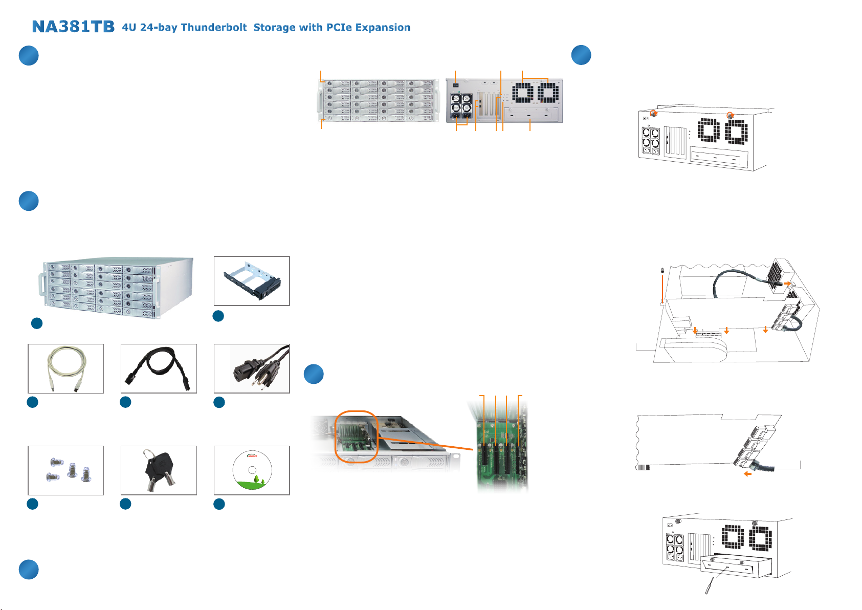
2.
Package Checklist
Before installing this unit, verify the package contains the following items.
HDD Tray x 24
A
Enclosure x 1
B
(installed in chassis)
1
2
3 96
5 7 84 10
1. HDD Power LED
。White - Power On Indicator
2. HDD Status LED
。Flash Blue - HDD Accessing Indicator, Red - HDD Failure Indicator
3. PSU power button
。“I” for enable, “0” for disable
4. Power cord receptacles
Thunderbolt connectors
5.
。Connecting ThunderboltTM cables to host and downstream device
6. Mute Button
。Reset for buzzer beeping
7. Fan Status LED
。Normal – Green
。Failure – Red (too slow RPM or stop)
8. Temperature LED
。Normal – Green
。Over 50°C – Red
9. Cooling fans
10. Swappable integrated plate drawer for
Mac mini/Mac mini Server
5. Building Up Procedures
1. Place NA381TB chassis on a level surface of a stable table.
2. Open the chassis by removing the top cover.
3. Three PCIe slots on rear of NA381TB are covered by removable
L-shape metal brackets. Unscrew the screw of the removable
L-shape metal bracket, and the PCIe slots are ready for installation
of PCIe cards.
4. Install one SAS/SATA RAID controller card and other PCIe cards into
proper PCIe slots of NA381TB and tighten them with screws on the
brackets of the PCIe cards.
RAID HBA
Enclosure
Slot 2
ThunderboltTM cable
C
(2 meters) x 1
D
HDD mounting
F
screw x 96
Internal mini-SAS
D
(SFF-8087) to
mini-SAS (SFF-8087)
cable
30 cm x 6
Key for HDD tray
G
x 2
Power cord x 2
E
Green IT makes
Green Earth
NetStor Technology Co. Ltd.
www.netstor.com.tw
Manual CD-ROM
H
x 1
Notify your sales representative if any of the above items is missing or
damaged.
3. Panel Layout
4. Hardware Configuration
slot 3 slot 2
slot 4
Slot 1 : ThunderboltTM target card
Slot 2 : PCIe x8 slot (RAID controller card is
Slot 3 : PCIe x8 slot (Supports PCIe card x1/x4/x8)
Slot 4 : PCIe x4 slot (Supports PCIe card x1/x4)
(already fixed in the chassis)
recommended to be installed in this slot because
it is closest to the connectors of backplane)
slot 1
5. Connect the cable between the topmost mini-SAS connector on
backplane and the mini-SAS connector Channel 1~4 on RAID card,
and connect the rest cables subsequently to the bottommost one on
backplane and Channel 21~24 on RAID card.
RAID HBA
mini-SAS cable
6. Loosen the two thumbscrews on swappable integrated plate drawer,
and pull it out. Use a tool to bend the metal board on plate drawer to
separate the metal board from drawer.
Page 3

TM
7. Unscrew the four screws on L-type bracket on plate drawer, place
the Mac mini Server into drawer, and restore the L-type bracket to
fasten Mac mini Server with drawer.
8.
Connect NA381TB and Mac mini Server with ThunderboltTM cable
9. Restore the top cover of NA381TB and immobilize the chassis on a
server rack or proper place.
10. Connect NA381TB with power source.
11. Take out the HDD trays.
12. Place the HDDs in the trays and fix them with hard drive mounting
screws. Put the trays with HDDs back to NA381TB.
6. Operation and Verification
3.
Verify HighPoint ThunderboltTM target card is recognized by Mac mini
Server. Click the Apple icon on top left of the screen, select About This
Mac, and then select More Info. Next, click System Report, and a pane
will pop up. Select ThunderboltTM on left side of the pane, and if
NA381TB can be selected to see the information, then the HighPoint
ThunderboltTM target card is recognized by Mac mini Server.
5.
Verify that the drivers of RAID controller card and PCIe cards are
installed on OS X. When seeing all the PCIe cards listed from the last
step, there will be a column Driver Installed which indicates the status
of PCIe cards’ drivers. If it shows “No” in the status, then find and install
the ThunderboltTM-aware driver of the PCIe card, and then the status
will become “Yes” to show the driver of the PCIe card has been
installed successfully.
6. After verifying that the driver of the RAID controller card is installed,
follow the operation procedure instructed by the manufacturer of the
RAID card to set up the RAID volume.
7.
While NA381TB is connected to Mac mini Server by Thunderbolt
TM
cable, when shutting down Mac mini Server, the NA381TB will be shut
down simultaneously as well.
•The following verification steps are for Mac OS X.
1. When NA381TB is connected to the power source with two power
cords connecting to PSU of NA381TB, turn on the power switch of
PSU (turn the switch to “I” position to enable the power supply).
turn the switch to
position “ I ”
2.
The NA381TB is designed to be powered on/off simultaneously with
Mac mini Server when NA381TB is connected to Mac mini Server by
ThunderboltTM cable. Therefore, power on Mac mini Server first, and
NA381TB will be powered on automatically. (NA381TB also
then
supports hot-plug and hot-unplug for powering-on and powering-off.)
Mac mini Server
Verify the PCIe cards installed in NA381TB. After the verification of
4.
HighPoint ThunderboltTM target card, click PCI Cards on left side of the
pane, and then all the PCIe cards installed in NA381TB will be shown in
the information area in the pane. (For RAID controller card, from starting
up, it will take more time for its info to be displayed.)
Notice: The NA381TB chassis supports SGPIO. When any HDD fails, the red
LED indicator on that tray will light. The SGPIO function will be effective when
the SAS/SATA RAID card supports SGPIO function (for example, Areca’s RAID
controller card).
If you have any questions, please contact your regional
distributor, or HighPoint Technologies, Inc.
HighPoint Technologies, Inc.
Address: 1161 Cadillac Court, Milpitas, CA 95035
E-mail: sales@highpoint-tech.com
Phone: (408) 240-6108 (Monday~ Friday, from 9am~6pm)
Skype: Highpoint.Thunderbolt
Support: www.highpoint-tech.com/websupport
 Loading...