

HighPoint 3700 Service Manual
RocketRAID 3700 Series
SAS 12Gb/s PCI-Express 3.0 x8 RAID Controller
User’s Guide
v1.03

2
Copyright
Copyright © 2019 HighPoint Technologies, Inc. This document contains materials protected by
International Copyright Laws. All rights reserved. No part of this manual may be reproduced,
transmitted or transcribed in any form and for any purpose without the express written
permission of HighPoint Technologies, Inc.
Trademarks
Companies and products mentioned in this manual are for identification purpose only. Product
names or brand names appearing in this manual may or may not be registered trademarks or
copyrights of their respective owners. Backup your important data before using HighPoint's
products and use at your own risk. In no event shall HighPoint be liable for any loss of profits, or
for direct, indirect, special, incidental or consequential damages arising from any defect or error
in HighPoint's products or manuals. Information in this manual is subject to change without
notice and does not represent a commitment on the part of HighPoint.
Notice
Reasonable effort has been made to ensure that the information in this manual is accurate.
HighPoint assumes no liability for technical inaccuracies, typographical, or other errors contained
herein.
FCC Part 15 Class B Radio Frequency Interference statement
This equipment has been tested and found to comply with the limits for a Class B digital device,
pursuant to part 15 of the FCC Rules. These limits are designed to provide reasonable protection
against harmful interference in a residential installation. This equipment generates uses and can
radiate radio frequency energy and, if not installed and used in accordance with the instructions,
may cause harmful interference to radio communications. However, there is no guarantee that
interference will not occur in a particular installation. If this equipment does cause harmful
interference to radio or television reception, which can be determined by turning the equipment
off and on, the user is encouraged to try to correct the interference by one or more of the
following measures:
Reorient or relocate the receiving antenna.
Increase the separation between the equipment and receiver.
Connect the equipment into an outlet on a circuit different from that to which the receiver is
connected.
Consult the dealer or an experienced radio/TV technician for help.
Modifications not expressly approved by the manufacturer could void the user’s authority to
operate the equipment under FCC rules.
This device complies with part 15 of the FCC Rules. Operation is subject to the following two
conditions: (1) this device may not cause harmful interference, and (2) this device must accept
any interference received, including interference that may cause undesired operation.
European Union Compliance Statement
This Information Technologies Equipment has been tested and found to comply with the following
European directives:
European Standard EN55022 (1998) Class B
European Standard EN55024 (1998)

3
Table of Contents
1. HighPoint RocketRAID 3700 Overview .......................................................................................................... 4
2. Board Layout & Hardware Installation .......................................................................................................... 5
3. What’s in the Box .......................................................................................................................................... 6
4. Using the RocketRAID 3700 .......................................................................................................................... 6
4.1. Using the RocketRAID Series HBA BIOS .................................................................................................. 6
4.1.1 RocketRAID BIOS Setting Utility ................................................................................................... 6
4.1.2 Using the BIOS Utility ................................................................................................................... 7
4.1.3 BIOS Commands ........................................................................................................................... 7
4.1.4 Creating RAID Arrays .................................................................................................................... 7
4.1.5 Delete Arrays ................................................................................................................................ 9
4.1.6 Add/Remove Spare Disks ............................................................................................................. 9
4.1.7 Settings ....................................................................................................................................... 10
4.1.8 View ........................................................................................................................................... 10
4.2. Driver & WebGUI Installation ............................................................................................................... 11
4.2.1 Driver and WebGUI Installation (Windows) ............................................................................... 11
4.2.2 Driver and WebGUI Installation (Linux) ..................................................................................... 11
4.2.3 Driver and WebGUI Installation (Mac) ....................................................................................... 12
4.3 Using the HighPoint WebGUI ................................................................................................................ 12
Verify the Controller Status ......................................................................................................................... 12
Creating an Array ........................................................................................................................................ 13
Adding Spare Disks ...................................................................................................................................... 15
Obtaining Logical Device Information ......................................................................................................... 17
Array Information &Maintenance Options: Normal Status ........................................................................ 17
Array Information & Maintenance Options: Critical Status ........................................................................ 18
Array Information & Maintenance Options: Disabled Status...................................................................... 18
Physical Device Information ........................................................................................................................ 19
System Setting ..................................................................................................................................................... 19
System Setting ............................................................................................................................................. 20
Password Settings ....................................................................................................................................... 20
Email Setting ............................................................................................................................................... 21
Event Tab ............................................................................................................................................................. 22
SHI (Storage Health Inspector) ............................................................................................................................ 23
How to Enable SMART Monitoring ............................................................................................................. 23
How to Use the Health Inspector Scheduler ............................................................................................... 24
How to Create a New Verify Task ................................................................................................................ 24
Troubleshooting .................................................................................................................................................. 25
Handling Critical Arrays ....................................................................................................................................... 25
Rebuilding Stops Due to Bad Sectors .......................................................................................................... 26
Critical array becomes disabled when you removed faulty disk ................................................................. 26
Handling Disabled Arrays .................................................................................................................................... 26
Help ..................................................................................................................................................................... 27
Table 1.HRM Icon Guide ...................................................................................................................................... 28
Table 2. RAID Level Reference Guide .................................................................................................................. 30
5. Customer Support ....................................................................................................................................... 31

4
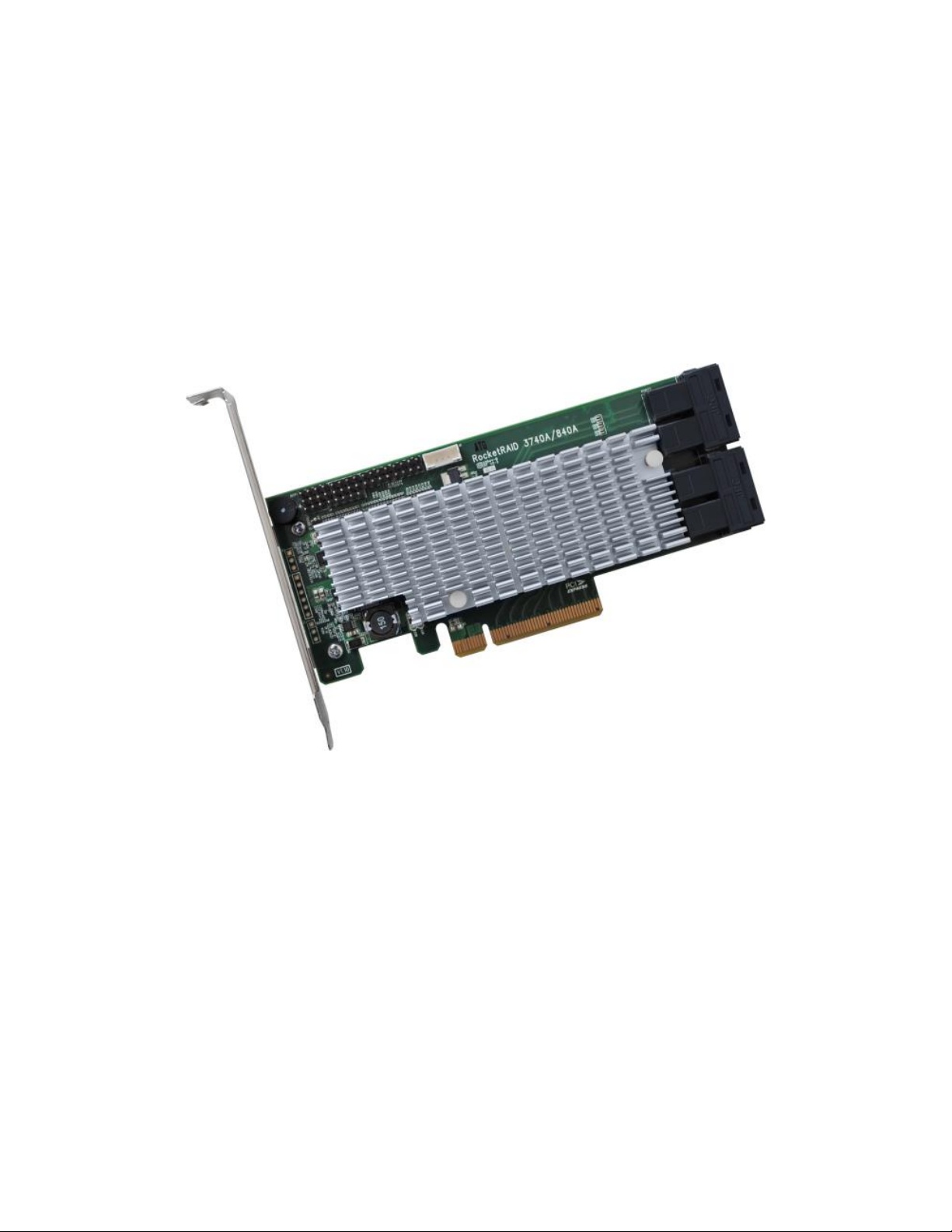
1. HighPoint RocketRAID 3700 Overview
RocketRAID 3700 series host bus adapters are the world’s most price competitive 12G SAS/SATA RAID controllers, and deliver
unprecedented end-to-end Generation 3.0 PCI Express transfer performance with Professional class RAID Storage reliability and
management capabilities.
RocketRAID 3700 series host bus adapters capitalize on HighPoint’s two decades of RAID and storage technology to deliver
professional grade RAID storage at a fraction of the cost of conventional host RAID solutions. Each adapter is powered by our
industry proven RAID technology, superior Gen 3.0 PCIe express transfer bandwidth, and up to sixteen dedicated 12Gb/s SAS
channels, which support robust, high-performance RAID 0, 1, 5 ,6, 10, 50 and JBOD configurations of SAS or SATA hard drives of
any disk format, including 512, 512e and 4Kn.
RocketRAID 3700 Technical Specifications
Bus Interface
8-lane, 8 GT/s PCI Express 3.0 Compliant
Number of Channel / Port
16x 12Gb/s SAS / 6Gb/s SATA Channels
Data Transfer Rates:
Up to 12Gb/s per port
Port Type
SFF-8643 mini-SAS HD and SFF-8644 mini-SAS HD
Number of Devices
16x SAS/SATA Hard Drive/SSD
Form Factor
Low Profile
Dimensions
5.97*2.68*0.06 (in)
Weight
0.26lb
RAID Level Support
0,1,5,6, 1/0,5/0 and JBOD / Non-RAID Mode
RAID 6 is not supported on macOS
Bootable RAID 6 arrays are not supported
RAID 1/0 is equivalent of RAID 10. RAID 5/0 is equivalent of RAID 5/0
Operating System
Windows 7 and later
Windows Server 2008 and later
Linux (Support Linux Driver auto Compile)
macOS
FreeBSD
RAID Feature Suite
Flash ROM for Upgradeable BIOS
Storage Health Inspector
Redundant RAID Configurations
BIOS PnP (plug and play) and BBS (BIOS boot specification) support
Bootable RAID Array
EFI for Mac Platform
Multiple RAID Partitions supported
Storage Configurations Support Details
Multiple RAID Adapters supported
Online Array Roaming
Online RAID Level Migration (ORLM)
Online Capacity Expansion (OCE)
RAID Quick Initialization for fast array setup
Drive hot plug support
Global Hot Spare Disk support
Automatic and configurable RAID Rebuilding Priority
Auto resume incomplete rebuilding after power on or reboot system
Disk Format compatible: 512, 512e, 4Kn
Larger than 2 TB Drive and RAID Array support
Spin down Massive Arrays of Idle Disks support
Native Command Queuing
SAS TCQ
Disk media scan and repair
Device Error Recovery support
Automatic remap and fix drive bad block for RAID array
Staggered Drive Spin Up
Write Back and Write Through
5
Configuration Management Suites:
User friendly Browser-based Management Interface
Easy to use BIOS configuration Tool
Linux Command Line Interface (CLI) – Scriptable configuration
tool
Monitoring and Management Support :
SGPIO, SES-2 and I2C
(Drive LEDs supported: SGPIO, SES-2 and LED Header)
Operating Temperature :
Work Temp: +5°𝐶 ~ + 55°𝐶. Storage Temp: −20°𝐶 ~ + 80°𝐶
Relative Humidity: 5% ~ 60% non-condensing.
Operating Voltage :
12 V / 3.3 V, Power: 14W (12V 1A, 3.3V 0.5A)
MTBF (Mean Time Before Failure):
920,585 Hours
Certification Approval:
CE FCC RoHS REACH WEEE
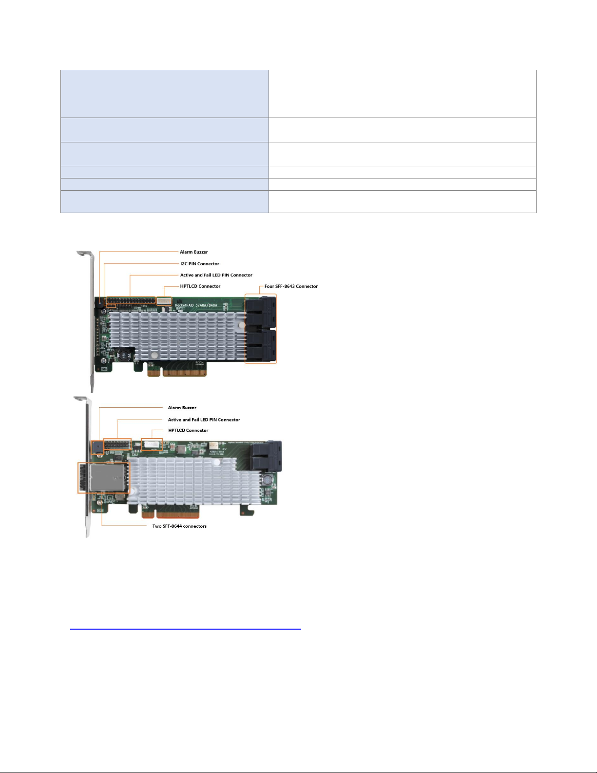
2. Board Layout & Hardware Installation
SFF-8643 and SFF-8644 connector
Each SFF-8643 and SFF-8644 connector supports 4 disk channels. Connect the hard disks or disk backplane to the
RAID controller using the appropriate data cables.
Active/FAIL LED PIN connector:
LED pins are provided for Active/Fail status for each of the device channels.
For more information about LED functionality and connection requirements, please refer to the document below:
http://www.highpoint-tech.com/PDF/LED_connection.pdf
Alarm Buzzer
Audible alarm will sound if a disk failed status occurs.
I2C Pin Connector
The I2C Pin connector can be used to connect an enclosure device with I2C protocol for enclosure management.
HPTLCD Connector
Connector for the optional HPTLCD module.
Hardware Installation
6
3. What’s in the Box
Make sure the following items are included in your purchase:
• RR3700 controller card
• Low Profile Bracket
• Quick Installation Guide
4. Using the RocketRAID 3700
4.1. Using the RocketRAID Series HBA BIOS
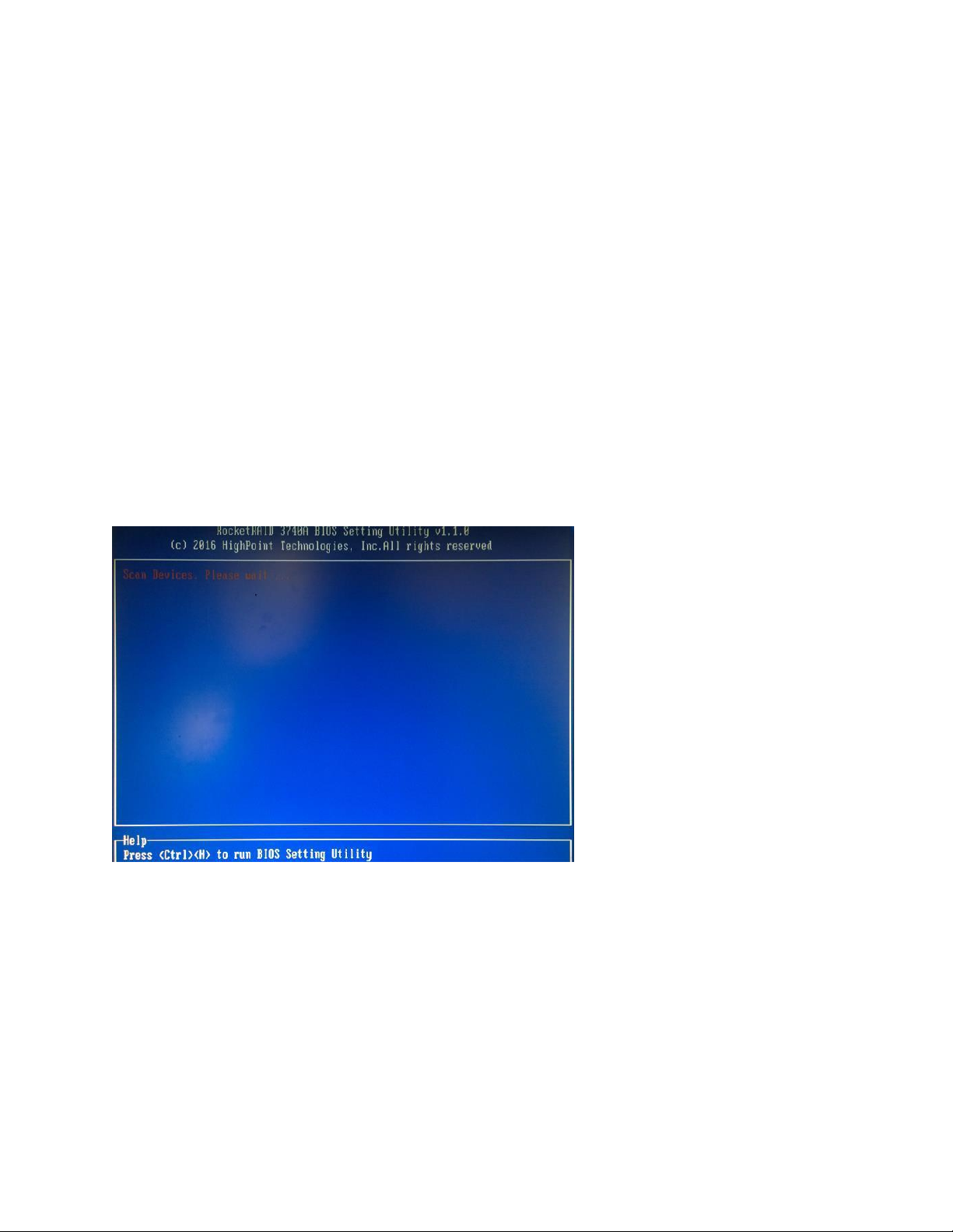
4.1.1 RocketRAID BIOS Setting Utility
The RocketRAID controller BIOS utility is an interface that provides management commands and controller related settings.
After installing the RAID controller and powering on the system, the RAID controller BIOS should post during the system’s boot
procedure.
Use Ctrl + H key to log-in to the BIOS setting utility. The BIOS setting utility can be used for RAID management. The BIOS Utility
will display information about hard drives attached to the adapter. Make sure all attached drives are detected by this utility. If
any of the hard drives is not detected, power down the system and check the power and cable connections.
Note: The following screenshots depict the RocketRAID 3700 BIOS utility. However, all RocketRAID models utilize the same
interface.
7
4.1.2 Using the BIOS Utility
The following keys are utilized by the RocketRAID BIOS utility:
Arrow keys – Use these to move between different menu items.
Enter – Open the selected toolbar command/execute the selected command.
Esc – Move back to the previous menu, cancel the selected operation, or exit the BIOS Utility.
4.1.3 BIOS Commands
Create: This command is used to open the RAID Creation menu.
Delete: This command will delete the selected RAID array.
Add/Remove Spare: This command is used to assign hard disks to function as spare disks. The controller is capable of using
spare disks to automatically rebuild broken or faulted RAID arrays.
Settings: This command opens the settings menu (To selecting the boot disk/array, staggered drive spin up etc.)
View: This command is used to view hard disk and RAID information.
Initialize: This command is used to prepare disks for use with RAID arrays. Disks must be initialized before they can be used to
create arrays.
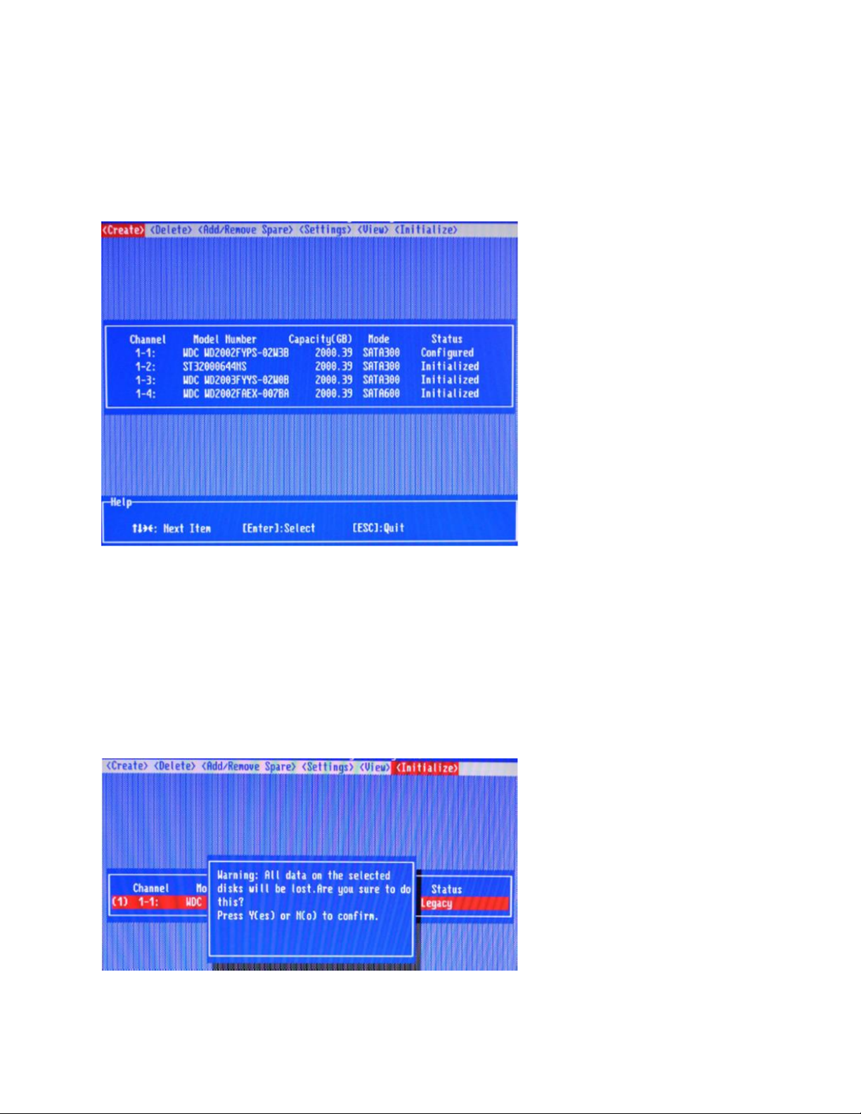
4.1.4 Creating RAID Arrays
Initializing Disks:
Before creating a RAID array, the disks must be initialized. Disk initialization writes necessary RAID configuration
information to the hard disks. Select the Initialize command from the toolbar, and press the Enter key.
Highlight the target disks using the arrow keys, and then press the Enter key. A numeral will be displayed before
each selected disk. Once all target disks have been selected, press ESC key. The utility will display a warning, and
ask you to press Y (yes) to initialize, or N (no) to cancel. Once initialized, these disks can be used to create RAID
arrays. These disks will be displayed as “Initialized” (under Status).
Warning: Initialization will destroy all pre- existing data on the selected hard disks. Only initialize disks that do not
8
contain critical data.
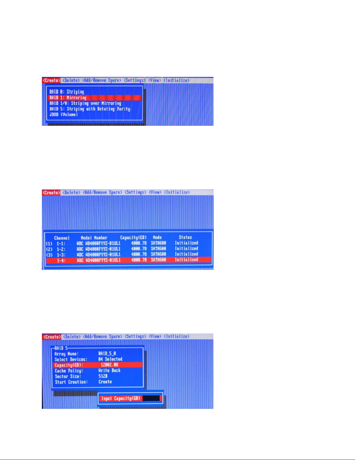
Create Arrays:
Select Create from the toolbar and press the Enter key.
1. Use the arrow keys to select the RAID level and press the Enter key.
2. Use the arrow keys to highlight the Array Name option and press the Enter key. The array name dialogue box
will appear. Use the keyboard to input a new Array Name, and press the Enter key.
Note: The Array Name command is optional – it is not necessary to name the array. The array can be named at a
later time, and the name of the array can be changed at any time.
3. On the Create menu, use the arrow keys to highlight the Select Devices item and press the Enter key. A device
list will appear, and display all available hard disk drives.
4. Highlight the target disks that you want to use, and press the Enter key to select them. A numeral will be
displayed before each selected disk. This number designates disk order. After all of the disks have been
selected and press the ESC key to return to the Create Menu.
5. Next, Use the↓arrow key to highlight the Capacity (GB) option and press the Enter key. The total available
capacity will be displayed. Press the Enter key if you wish to use all available space. If you wish to reserve disk
space for additional arrays/single disks, use the keyboard to input the amount of space (in GB) you wish to set
aside for this particular array, and press the Enter key.
Note: Multiple arrays can be created using the same set of hard disk drives. The Capacity option allows you to set
aside disk space that be used to create another array, set as a spare disk, or partitioned to act as a single disk (by
the operating system).
9
6. For redundant RAID arrays (RAID 5, 50), select the Cache Policy:
Write Back – Provides higher write performance for redundant RAID arrays. Data is at risk when there is a
power failure, system kernel panic and unresponsive abnormal conditions.
Write Through – Writes directly to the disks (may reduce the risk of data loss during a critical failure, but at
the cost of lower performance).
7. Sector Size – Also known as “Variable Sector Size”. Use this option if you are using an older 32-bit Windows
operating system. This allows older operating systems to support volumes over 2TB in size. Do not use if the
operating system already supports large volumes (such as GPT).
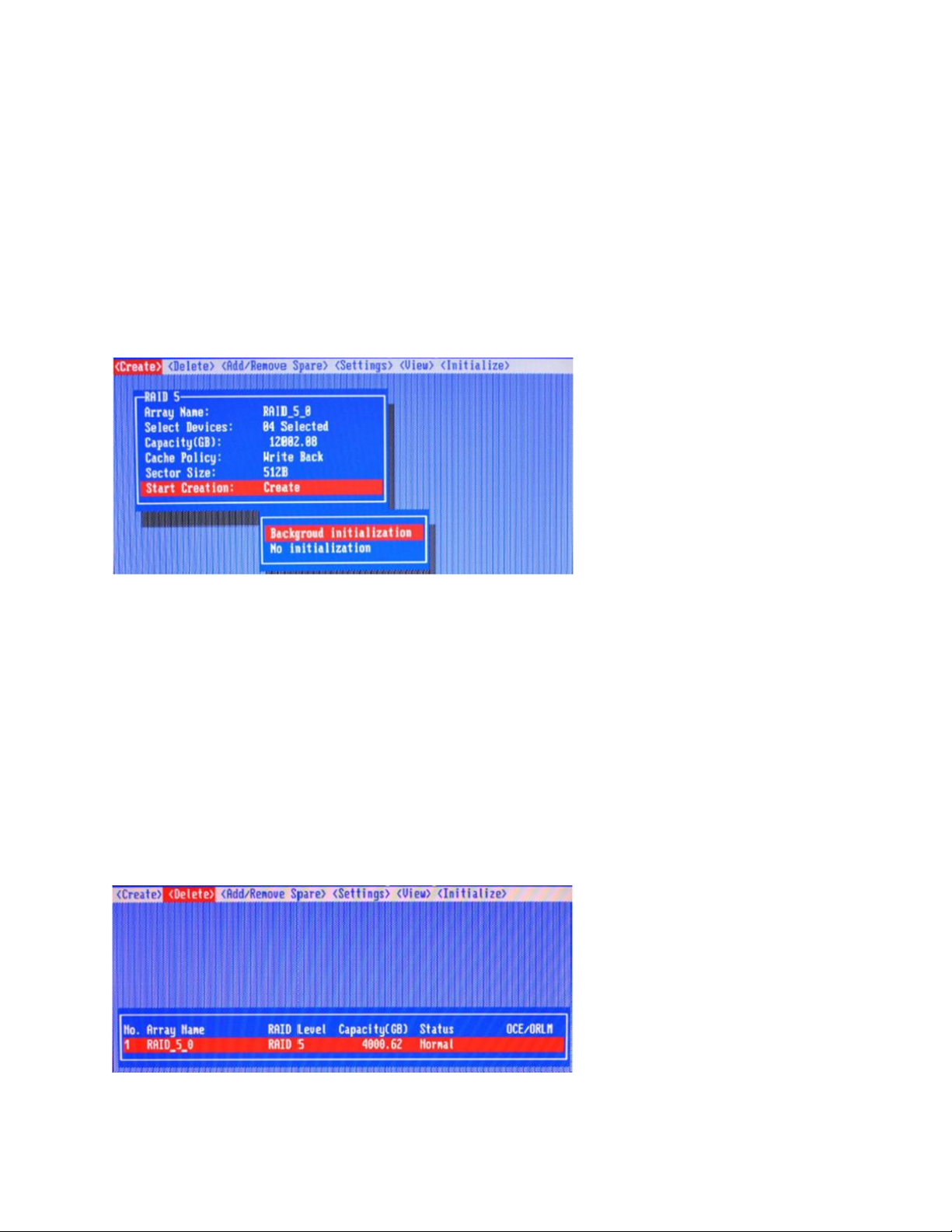
8. To complete the creation procedure, use the arrow key to highlight the Start Creation item and press the Enter
key.
The Window will show 2 options when creating a RAID 5 array: Background Initialization and No initialization.
Background initialization:
The RAID array is accessible while disk initialization is being performed.
A. This option will delete all content on the disks.
B. The initialization time will be longer when compared to "Foreground" but the logical drives can be used
during the initialization process.
No initialization:
The No initialization option is recommended for use when rescuing an original array of for testing purposes.
This option will not make any changes to the data area of each disk. When you select this option, a pop-up
window will display; press Y (yes) to create the array, or N (no) to cancel the creation process.
4.1.5 Delete Arrays
Highlight the Delete command from the toolbar, and press the Enter key.
The BIOS utility will display a list of available RAID arrays. Select the array you wish to delete, and press the Enter
key.
The utility will display a warning message. Press Y (yes) to delete the array, or select N (no) to cancel.
Warning: All data stored on the array will be lost – do not delete if the array contains critical data.
4.1.6 Add/Remove Spare Disks
The Add/Remove Spare command is used to assign a hard disk to act as a Spare Disk. Spare Disks are used to
10
automatically rebuild Redundant RAID arrays (RAID 1, 5, 10) in the case of disk failure. As with creating RAID arrays,
disks must be initialized before they can be used as spares. To set a hard disk to act as a Spare Disk, use the arrow
keys to select the target disk from the list of initialized disks, and press the Enter key. To remove the Spare Disk
setting from a hard disk, highlight the spare disk, and press the Enter key. Generally, single disks are designated to
act as spares (disks that are not configured into RAID arrays). However, in some instances, disks that are members
of RAID arrays may also be designated to act as a spare. If the disks in question are part of a RAID array that did not
utilize the full available capacity at the time of creation, these disks may be used as spares.
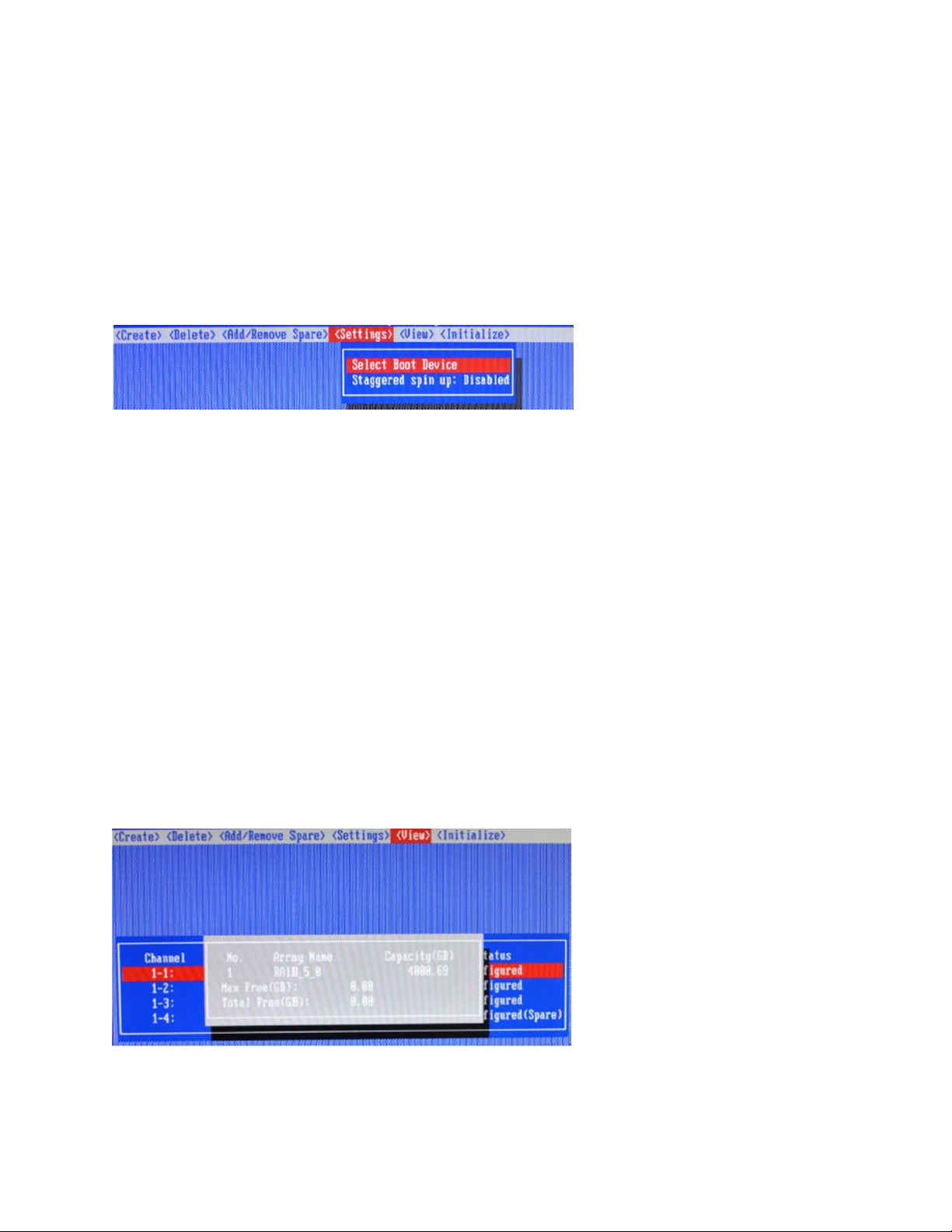
4.1.7 Settings
To access the Settings menu, highlight the Settings command from the toolbar, and press the Enter key. There are
Select Boot Device and Parameter Setting options in the menu.
Select Boot Device:
Select which disk or array will act as the boot disk, if the motherboard BIOS instructs the card to act as the boot
device.
▪ When booting up the system, press CTRL + H during the HighPoint RocketRAID splash screen to enter the
BIOS RAID creation utility.
▪ Navigate to Settings using arrow keys.
▪ Press Enter.
▪ Press Enter again.
▪ Select the desired RAID array.
▪ You will return to the main screen once the boot flag is set
Staggered Spin up:
The default value of this option is disabled. Enabling this setting will instruct the card to power up the hard disks,
sequentially (one disk approximately every 2 seconds). Not all disk support this setting – consult the disk
documentation for more information.
4.1.8 View
The View menu provides two options:
Devices – This option will display information for each disk hosted by the HBA.
RAID Array – This option will display information about each RAID array hosted by the HBA. Highlight the target
device and press the Enter key to view details about the configuration.
 Loading...