

Page 1

RocketRAID 2240
SATAII Host Adapter
Us er’s Guide
Revi sion: 1.0
Date: A pril 2005
Hi ghPoint Technologies, Inc.
Page 2

Co pyright
Copyri ght © 2005 HighPoint T echnologies, Inc. This document contains materials
prot ected by International Copyright Laws. All rights reserved. No part of this
manual may be repro duced, transmitted or transcribed in any form and for any
purpo se without the express written permission of HighPoint Technologies, Inc.
Tra demarks
Companies and products ment ioned in this manual are for identification purpose only.
Product names or brand names appearing in this manual may or may not be registered
trademarks o r copyrights of their respective owners. Backup your important data
bef ore using HighPoint ’s pr oducts and use at your own risk. In no event shall
HighPoint be liable for any loss of profits, or for direct, indirect, special, incidental or
consequential damages aris ing from any defect or error in HighPoint’s produc ts or
manuals. Infor mation in this manual is subject to change without notice and does not
represent a commitment on the part o f HighPoint.
N otice
Reaso nable effort has been made to ensure that the information in this manual is
accurat e. HighPoint assumes no liability for technical inaccuracies, typographical, or
other er rors contained herein.
Page 3

Chapter 1
Introduction
Table of Contents
Ta ble of Contents
A bout this Guide......................................................................................................
Introducing the RocketRA ID 2240 Host Adapter...............................................
Product Features......................................................................................................
Under standing RAID Concepts and Terminology..............................................
Chapter 2
RocketRAID 2240 Hardware Descri ption/Installation
RocketRAID 2240 Hardware...................................................................................
1 – RocketRAID 2240 Adapter Layout.................................................................
2 - LED Connections................................................................................................
3 - Installing the RocketRAID 2240 Host Adapter..............................................
4 - Verifying Installation..........................................................................................
Chapter 3
RocketRAID 2240 BIOS Utility
RocketRA ID 2240 BIOS Utility...............................................................................
1 - BIOS Command Overview.................................................................................
2 - Creating RAID Arrays........................................................................................
3 - Adding/Removing Spare Disks.........................................................................
1-1
1-1
1-1
1-2
2-1
2-1
2-2
2-3
2-4
3-1
3-1
3-3
3-4
Chapter 4
RocketRAID 2240 Driver and Software Installation
Microsoft Windows (2000, XP, 2003 Server, x64 versions)
Driver and Software CD..........................................................................................
Windows Driver Installation..................................................................................
1 - Installing the RAID Management Console/ Interface Overview................
2 - Software Interface - Overview of commands/functions...............................
3 - Creating an Array................................................................................................
4-1
4-3
4-5
4-7
4-8
i
Page 4

Table of Contents
4 - Deleting an Array...............................................................................................
5 - Configuring Spare Disks...................................................................................
6 - Recovering/Verifying Arrays............................................................................
7 – OCE/ORLM........................................................................................................
8 - Misc. Array/Device Options.............................................................................
9 - Managing Events...............................................................................................
10 - Configuring Remote Systems.........................................................................
11 - Configuring Users and Privileges..................................................................
Chapter 5
Linux Driver Support
Fedora Core 3 Linux installation Overview..........................................................
Red Hat Enterprise 3 Overview..............................................................................
SuSE Linux Enterprise Server (SLES) installation Overview.............................
Chapter 6
FreeBSD Driver Support
4-10
4-10
4-11
4-12
4-13
4-15
4-20
4-24
5-1
5-5
5-10
1 - Installing FreeBSD on the RocketRAID 2240 Controller..............................
2 - Installing RR2240 Driver on an Existing System............................................
3 - Updating the Driver...........................................................................................
4 – Uninstalling the Driver.....................................................................................
Appendix
Customer Support
Customer Support....................................................................................................
6-1
6-4
6-7
6-7
A-1
ii
Page 5

Contents of this Chapter:
About this Guide
Introducing the RocketRAID 2240 Host Adapter
Product Features
Understanding RAID Concepts and Terminology
Chapter 1
Introduction
Page 6

Introduction
About this Guide
T he RocketRAID 22 40 SAT AII Host Adapter’s User’s Guide pro vides information
abo ut the functions and capabilities of the host adapter, and instructions for
ins talling, configuring and maintaining RAID arrays hosted by the adapter.
I ntroducing the RocketRAID 2240 Host Adapter
T he HighPoint RocketRAID 2 240 is a 16-channel Multi-Port Infiniband Serial AT A II
RA ID controller. It utilizes a 64bit, 133MHz PCI-X interface. The RocketRAID 2240
sol ution is aimed at enterprise storage applications, NAS storage, workgroup and web
ser vers, video streaming / video editi ng workstations, back up, and security systems.
Product Fea tures
• 16-Channel Multi-Port Infiniband SAT A II RAID Controller
• PC I-X 64 bit 133/100/66 MHz
• 4 Infi niband connectors for reliability and easy installation
• RA ID 0, 1, 5, 10 and JBOD
• Native Command Queuing (NCQ)
• Ho t swap and hot spare support
• Online Capacity Expansion and Online RA ID Level Migration (OCE/ORLM)
• SA F-TE Enclosure management ready
• St aggered drive spin-up support
• Hard disk activi ty and failed hard disk LED support
• S.M.A .R.T monitoring of hard disk s tatus for reliability
• A uto matic RAID rebuild
• BIOS booti ng support
• Online arr ay roaming
• Quick and Background initializat ion for quick RAID configuration
• Supports 64-bit LBA for over 4TB partition
• Web-bas ed RAID management software
• Command Line Interface (CLI) for Linux and FreeBSD operating systems
• SMT P support for email notification
• Oper ating systems support for Windows, Linux and FreeBSD
1-1
Page 7

Introduction
Under standing RAID Concepts and Terminology
T he following concepts and terminology is co mmonly used when describing the
functi ons of the RocketRAID 2240 Host Adapter.
Disk initialization
Initiali zing a disk writes necessary RAID configuration information to that disk. Disks
must be initialized before configuring them into RA ID arrays. The initialization
proce ss will destroy all data on the disk.
Disk Status
Ne w T he disk contains no data and has not been initi alized.
Initia lized T he disk has been initialized and can be used for array creation.
Configured T he disk has been assigned to one or more arrays , or configured as a
spare di sk.
Leg acy T he disk was used on other controllers before use with the
RocketRA ID 2240 (see legacy disk below).
Array initialization
A redundant array (RAID5, RAID1, RAID10) needs to be initialized to ensure full
perfor mance and reliability. Non-redundant arrays (RAID0, JBOD) do not need to be
initialized.
When you create a redundant ar ray using the RocketRAID 2240 controller’s BIOS
Configuration Utility, it will create the array in un-initialized state. The initialization
proc ess can be completed after installing the driver and management software.
Whe n creating an array using the HighPoint RAID Management Console software,
you can specify an initialization optio n (Skip initialization, foreground and
backgr ound).
1-2
Page 8

Introduction
Foreground initialization
Foreground initializati on will zero-out all data on the array. The array is not ac cessible
by the operating system until initializatio n is complete.
Background initialization
Backgro und initialization allows the array to be used immediately. For RAID1 and
RA ID10 arrays, initialization will results in data being duplicated identically to the
mirror pair. For RAID5 arrays, initialization will result in parity being generated from
all array members.
Note: An un-initialized RAID1 or RAID10 array can still provide redundancy in case
of a disk f ailure. A RAID5 array, however, is not fault-tolerant until initialization is
finis hed.
Online Capacity Expansion (OCE)
T his feature allows disks to be added to existing RAID arrays, in order to increase the
arr ay’s capacity, without fear of data loss. Any number of disks can be added to an
array, at any time. Data can be acc essed and utilized even while being redistributed.
Online RAID Level Migration
T his term describes the ability to change one type of array (RAID level), into a
different t ype of array (changing a RAID 1 array into a RAID 10 array for example).
Data i s still accessible during the migration process, and a base level of security is
still active.
OC E, ORLM and the RocketRAID 2240
T he RocketRAID 2240 supports both Online Capacity Expansio n (OCE), and Online
RA ID Level Migration (ORLM). Bo th features are supported by a single function - an
array can be transformed from o ne RAID level to another RAID level while simultaneo usly being resized, even under I/O load.
1-3
Page 9

Introduction
Spa re disk
A spare disk is a single disk that c an be used to automati cally rebuild a redundant
array in case of drive failure. Spare disks may also be members of a RAID array. Any
availabl e space on these disks may be used to rebuild other broken arrays.
Legacy disk
Disks attached to the RocketRAID 2240 that contain valid partition tables will be
identi fied as legacy disks. A legacy disk attached to the RocketRAID 2240 can be
acc essed by the operating system, but cannot be used to create RAID arrays. A
legacy disk must be initialized before assigning it to an array.
1-4
Page 10

Hardware Description/Installation
Contents of this Chapter:
RocketRAID 2240 Hardware
1 – RocketRAID 2240 Adapter Layout
2 - LED Connections
3 - Installing the RocketRAID 2240 Host Adapter
4 - Verifying Installation
Chapter 2
RocketRAID 2240
Page 11
RocketRAID 2240 Hardware Description/Installation
RocketRAID 2240 Hardware
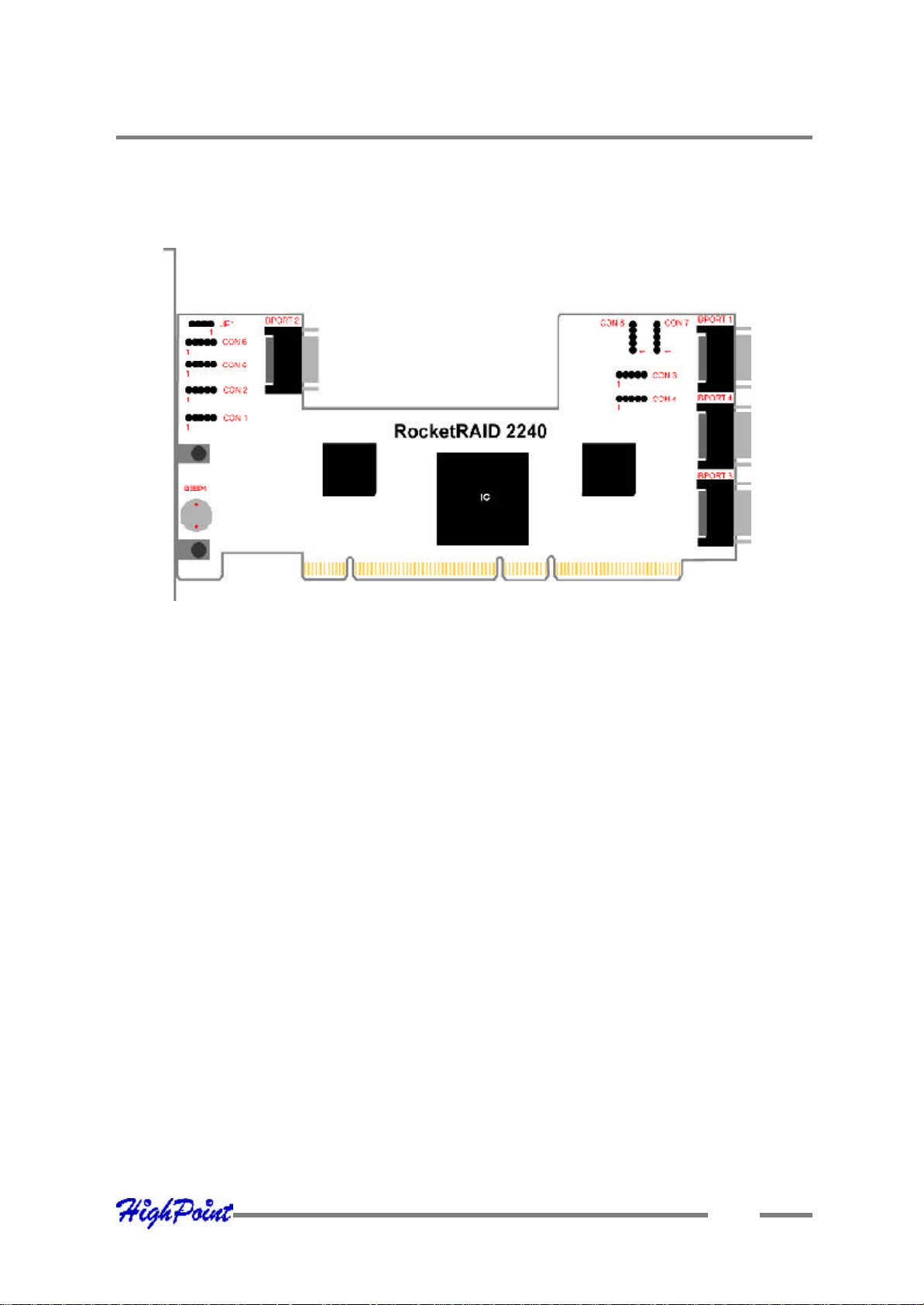
1 – RocketRAI D 2240 Adapter Layout
IBPort1- IBPort4
T hese represent the RocketRAID 224 0’s 4 Infiniband SATA c onnectors. Each of
thes e 4 connectors hosts up to 4 SATA disks, for a total of 16 hard disk drives. These
disks are referred to as “Port” or channels 1-16.
CON1 – CON8
LED connectors (disk-activity/disk-failure) : Each Infiniband channel (port) utilizes
tw o of these c onnectors. CON1-4 are for use with hard disk activity LED’s, while
CON5-8 provides disk failure LED support. LED suppor t is discussed in greater detail
in the LED Connection section (page 2-2), and in a separate document, the
RocketRA ID 2240 LED guide (which discusses LED installation for specific server
chassi s, and will be available in downloadable form from our website).
JP1
SA F-TEE connector (connection be tween chassis and host adapter)
Speaker (“BEEP1”)
A larm: the speaker emits an audible alarm in the case of disk/array failure.
2-1
Page 12
RocketRAID 2240 Hardware Description/Installation
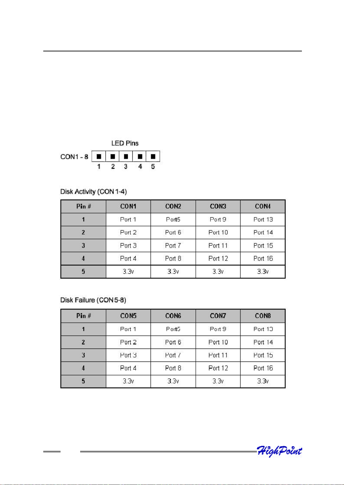
2 - LED Connections
T he table below is also printed on the surface of the card for quick reference.
T he use of the term “Port”, in the table below, refers to the SAT A channel/ hard disk
(1-16), as r eported by the RocketRAID 22240’s BIOS and RA ID Management
software.
2-2
Page 13
RocketRAID 2240 Hardware Description/Installation
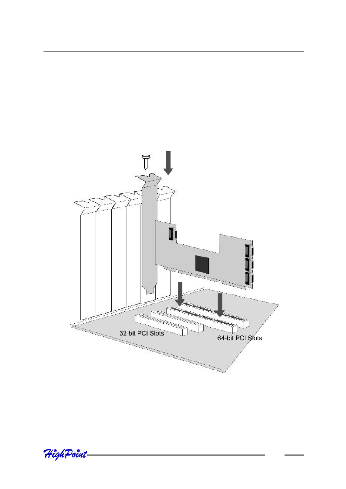
3 - Installing the RocketRAID 2240 Host Adapter
Note: Make sure the syste m is powered-off before installing the RocketRAID 2240
ho st adapter.
1. Ope n the system chassis and locate an unused PCI-X slot.
2. Remove the PCI slot cover.
3. Gently insert the Ro cketRAID 2240 into the PCI slot, and secure the bracket to
the system chassi s.
4. A fter installing the adapte r, attach the Infiniband connectors to the RR2240’s
Infini band ports, and to chassis backplane. Each Infiniband cable supports up
to 4 hard dis k drives. Consult the chassis’s manual fo r proper installation
pro cedures.
5. Clo se and secure the system chassis.
2-3
Page 14

RocketRAID 2240 Hardware Description/Installation
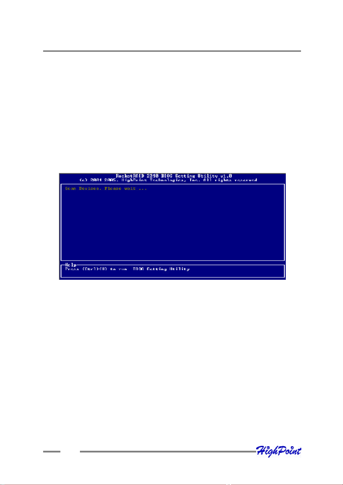
4 - Verifying Installation
Onc e the RocketRAID 2240 host adapter and hard disks have been installed into the
chassis, boot- up the system to verify that the hardware is proper ly recognized.
1. Pow er on the system. If the system detects the pres ence of the adapter, the
RocketRA ID 2240 BIOS will be displayed.
2. Press Ctrl +H to access the RocketRAID 2240 BIOS Utility.
T he BIOS Utility will display information about hard disks attached to the adapter.
Make sure all attached disks are detected by this utility. If any of the hard disks are
not detected, power down the system and check the power and Infiniband cable
connections. Make sure the hard disk in question is sec urely installed into the
cor responding removable drive tray.
2-4
Page 15

RocketRAID 2240 BIOS Utility
Contents of this Chapter:
RocketRAID 2240 BIOS Utility
1 - BIOS Command Overview
2 - Creating RAID Arrays
3 - Adding/Removing Spare Disks
Chapter 3
Page 16
RocketRAID 2240 BIOS Utility
RocketRAI D 2240 BIOS Utility
T he RocketRAID 2240’s BIOS Utility can be accessed usi ng the “Ctrl+H” command.
T his command should be displayed automatically when the Ro cketRA ID 2240’s BIOS
scr een appears during the system’s boot up procedure.
1 - BIOS Command Overview
T he RocketRAID 2240 BIOS Utility provides a wide selection of RAID related
commands. These co mmands are displayed towards the top of the utility’s interface.
Use the ← →arrow keys to scroll through the various commands, and the↑ ↓arrow
keys to browse through the corresponding command menus. Use the ENTER key to
execute the selected command.
The ESC button can be used to cancel the selected command, or return to the previous command menu.
Create - t his command is used to create RAID arrays. Page 3-3 discusses this
command in detail.
Delete - this command w ill delete the selecte d RAID array.
W arning: This command may result in permanent data loss - it should only be used
if data stored on the target array is no longer relevant, or has been backed up to an
alternate storage device.
3-1
Page 17

RocketRAID 2240 BIOS Utility
Add/Remove Spare - this command is used to assign hard disks to func tion as
spare disks. The controller is capable of using spare disks to automatically rebuild
broken o r faulted RAID arrays. Page 3-4 discusses this command in detail.
S ettings
Set Boo t Mark - this function is used to designate a particular disk or RAID array to
functi on as the RocketRAID 2240’s boot device.
Note: This setting is only relevant if the motherboard’s BIOS has set the
RocketRAID 2240 to function as the system’s primary boot device.
Sta ggered spin up – This function is used to enable (or disable) staggered drive
spin up suppor t. Staggere d drive spin up, by default, is disabled. When enabled, the
RocketRA ID 224 0 will power up the hard disks one at a time, approximately every two
s econds.
View – this command i s used to select between two views. Press the ENTER key to
change t he view.
Devi ces – displays information about hard disks attached to the RocketRAID 2240.
Use the ↑ ↓ arro w keys to highlight the target hard disk, and press ENTER to view
the information.
RA ID arrays – displays information about RAID arrays attached to the RocketRAID
2240. Use the ↑ ↓ arrow keys to highlight the target array, and pre ss ENTER to view
the information.
Initia lize - this function is used to prepare disks for use with RAID arrays.
Note: Arrays can not be created between disks that have not been initialized.
Section x - 2 discusses this command in detail.
3-2
Page 18

RocketRAID 2240 BIOS Utility
2 - Creating RAID Arrays
Initializing Disks:
Before creating a RA ID array, the disks must be initialized.
Initialization w rites necessary RAID configuration information to the hard disk.
Use the ← →arrow keys to select the Initialize command, and press ENTER.
W arning: Initial ization will destroy all pre- existing data on the selected hard
disks.
Use the ↑ ↓ arrow keys to highlight the target hard disk(s) and press ENTER. Next,
press the Y (yes) key to initialize the selected disk(s), or N (no) key to cancel the
initialization process.
Once init ialized, these disks can be utilized to create RAID arrays.
To create an array:
1. Use the ← → arrow keys to highlight the Create command, and press ENTER to
ope n the Create Menu.
2. Use the ↑ ↓ arro w keys to select the appropriate RAID level, then press ENTER.
3. Next, use the ↓ arrow key to highlight the Array Name optio n and press ENTER.
T he array name dialo gue box will appear. Use the keyboard to input a new Array
Name , and press the Enter key.
Note: the Array Name co mmand is optional – it is not necessary to name the
array. The array can be named at a later time, and the name of the array can be
chang ed at any time.
4. On the Create menu, use the ↓ arrow key to highlight the Select Devices item and
pres s ENTER. A device list will appear, and display all available hard disk drives.
5. Highlight the target disks that you want to use, and press ENTER to select them.
A fter all of the disks have been selected, press the ESC key to return to the
Cre ate Menu.
3-3
Page 19

RocketRAID 2240 BIOS Utility
6. Next, Use the ↓ arrow key to highlight the Capacity (GB) option and press
ENT ER. The total available capacity will be displayed. Press ENTER if you wish
to use all available space.
7. If you w ish to reserve disk s pace for additional arrays/single disks, use the
keyboard to input t he amount of space (in GB) you wish to set aside for this
parti cular array, and press ENTER.
Note: Multiple arrays can be created using the same set of hard disk drives.
The Capa city option allows you to set aside disk space that be used to create
another array or set as a spare disk.
8. To compl ete the creation procedure, use the ↓ arrow key to highlight the Start
Creati on item and press ENTER.
3 - Adding/Removing Spare Disks
T his command is used to assign a hard disk to act as a Spare Disk.
Spare Disks are us ed to automatically rebuild Redundant RAID arrays (RAID 1, 5, 10)
in the case of disk failure. To set a hard disk to act as a Spare Disk, use the ↑ ↓ arrow
keys to select a disk, and press ENTER.
To r emove the Spare Disk setting from a hard disk, highlight the spare disk, and press
ENTER.
Gene rally, single disks are designated to act as spares (disks that are not configured
into RA ID arrays).
How ever, in some instances, disks that are members of RAID arrays may also be
des ignated to act as a spare. If the disks in question are part of a RAID array that did
not ut ilize the full available capacity at the time of creation, these disks may be used
as spares.
For example: a RA ID 0 array was created between two 200GB hard disks, but only
200GB of space (out of a grand t otal of 400GB), was assigned to that array. In this
example, 200GB of disk s pace remains unallocated. This unallocated space would
all ow these disks to be set as spares for a separate redundant array that falls into the
same capacity range (200GB).
3-4
Page 20

Chapter 4
RocketRAID 2240
Driver and Software Installation
Microsoft Windows
(2000, XP, 2003 Server, x64 versions)
Page 21
RocketRAID 2240 Driver and Software Installation
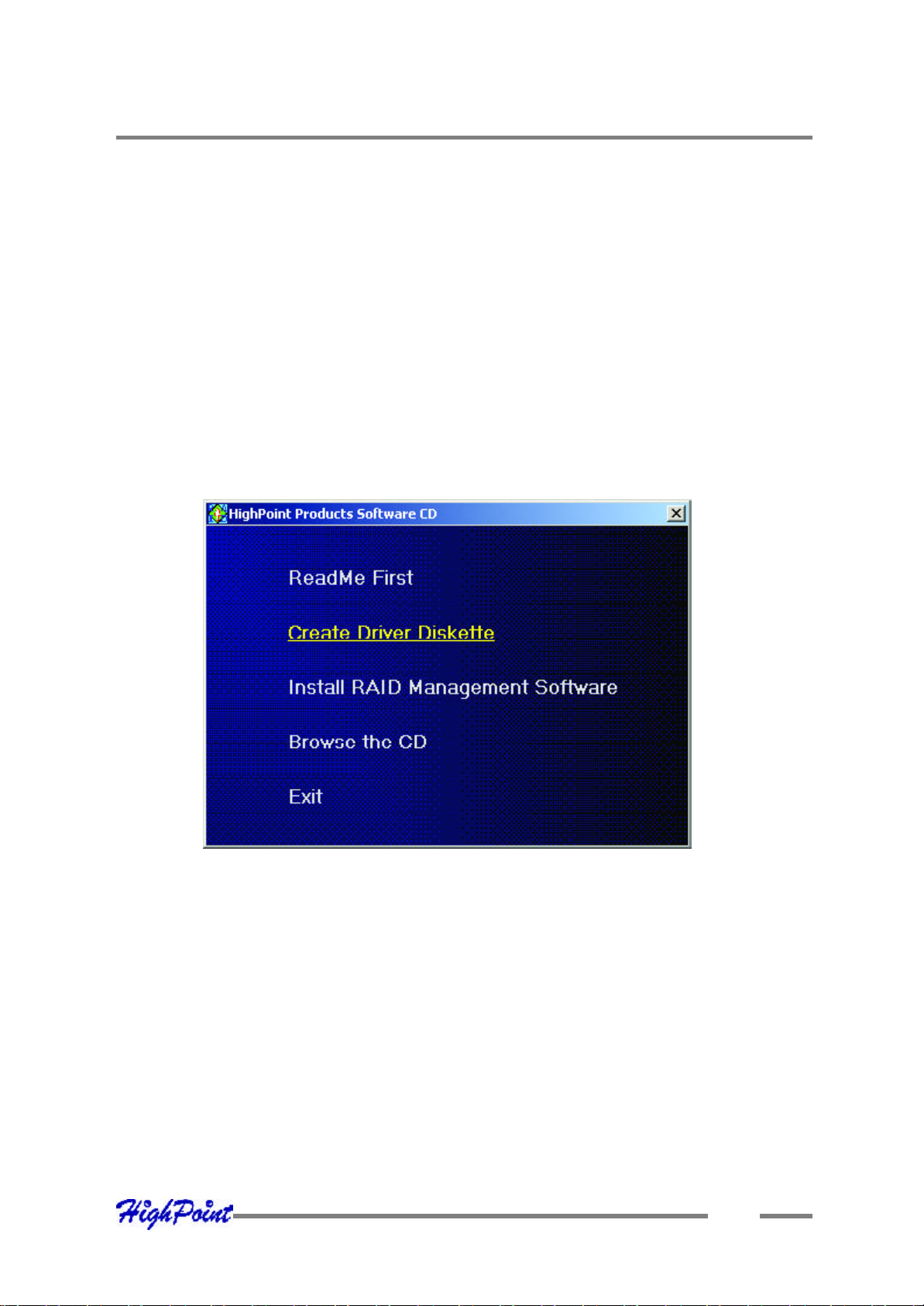
Dr iver and Software CD
T he RocketRAID 2240 retail box includes a Driver and Software CD.
T his CD can be used to generate driver diskettes, and install the RAID Management
soft ware for a variety of operating systems.
To create a driver diskette:
1. Inse rt the CD into the system’s CD/DVD drive. The program should start
automat ically.
2. Inse rt a blank floppy diskette into the system’s floppy drive.
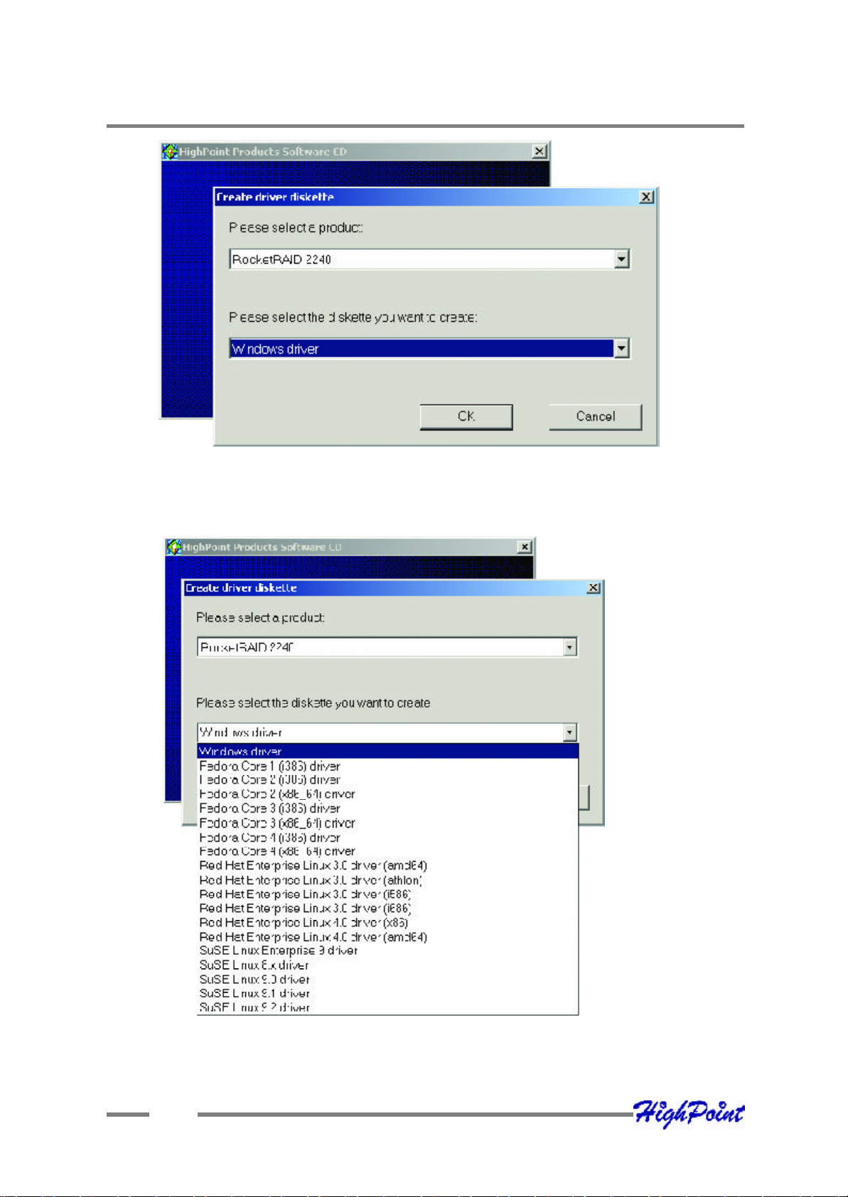
3. Click on “Create Driver Diskette”.
4. Clic k on the “Please Select a Product” drop-down button, and select
‘RocketRAID 2240” from the list.
4-1
Page 22
RocketRAID 2240 Driver and Software Installation
5. Clic k on the “Please Select the Diskette you w ant to create” drop- down button,
and select the appropriate OS fro m the list.
6. Click on the “OK” button to create the driver diskette.
4-2
Page 23

RocketRAID 2240 Driver and Software Installation
To install the RAID software:
1. Clic k on “Install RAID Management Software”.
2. Selec t the desired software from the drop down menu, and click on the “OK”
but ton.
Windows Driver Installation
Before installing the RocketRAID 2240 device driver, make sure the RocketRAID 2240
hos t adapter and all required hard disks have been installed into the system’s chas sis
(refer to the Hardw are Installation section, page 2-3).
Insta lling the RocketRAID 2240 driver for an existing Windows XP/
2 003/x64 system
A fter the operating system has booted, Windows XP/2 003 will automatically detect
the Ro cketRAID 2240, and request that a device driver be installed. T o install the
device driver, follow the steps outlined below:
4-3
Page 24

RocketRAID 2240 Driver and Software Installation
1. Whe n the “Found New Hardw are Wizard” window appears, select “Install from a
list or s pecific location (Advanced)”, and click Next to continue.
2. Clic k on the “Include this location in the search” option, and select the system’s
floppy drive (generally Disk A). Next, insert the Driver Installation diskette into
the system’s floppy drive.
3. A t the Hardware Wizard screen, select the floppy drive as the source, then click
the Next button. Se lect the appropriate operating system folder, then click the
Next butt on.
4. Wi ndows will display a warning message that states the driver has “not been
signed”. Select “Continue Anyway”, then click Finish when prompted. When
w indows asks to reboot the system, choose No.
5. Window s will then display a sec ond “Found New Hardware Wizard” windo w –
repe at steps 1 through 4.
6. Remo ve the Driver Installation diskette from the floppy drive, then Shut down
and restar t the computer.
Installation Verification
A fter the driver has be en installed, and the system has been restarted:
1. Clic k the Start button, select “Settings”, and then select “Control Panel”.
Double c lick the “System” icon.
2. In the pop-up w indow, selec t the Hardware tab, and then click the “Device
Manage r” button.
3. Double cli ck the “SCSI and RAID controllers” entry - two “RocketRAID 2240”
entries should be pre sent. If either one of the RocketRAID 2240 device entries is
not displayed, or ther e are “?” or “!” marks displayed near the Ro cketRAID 2240
entrie s, the driver has not been installed properly. Delete the entries and reinstall
the dr iver.
4-4
Page 25

RocketRAID 2240 Driver and Software Installation
Insta lling the RocketRAID 2240 driver during a fresh Windows 200 0/
XP /2003/x64 installation
1. A fter booting from the Windows 2000/XP/2003 CD-ROM, when the Windows XP
Setup blue s creen appears, look towards the bottom of the screen. Windows will
prompt you t o press the F6 key if you want to install a third party SCSI or RA ID
driver. Press the F6 key at this time.
2. T he setup procedure will continue, and will later instruct you to press the “S” key
to speci fy additional adapters. Press the “S” key as instructed.
3. Next, the setup program w ill prompt for the insertion of the driver diskette. Please
inse rt the driver diskette, and then press ENTER to continue.
4. T he next window will display several driver options. Please select the
RocketRA ID 2240 Controller for the corresponding operating system, and press
ENT ER to continue.
1 - Installing the RAID Management Console/ Interface Overview
To inst all the RAID software, locate the setup.exe file located on the floppy diskette
labeled “DISK 1” (or the Disk1 folde r, if the software was downloaded).
Double click this file to st art the Installation Wizard.
Note: If the system chassis supports SAF-TE, make sure to select the corresponding
chassis-type/manufacturer when prompted.
T here is no need to restart the system after installing the so ftware. T o start the
soft ware, click on the “Star t” button, select “Programs”, and click on the “HPT
Manage ment Console.”
Lo gging On
T he RAID Management Console requires that a user (or Administrator) log on.
T he software is incapable of working with RAID arrays or hard disks attached to the
RocketRAID 2240 until t he user has logged on.
4-5
Page 26

RocketRAID 2240 Driver and Software Installation
Defaul t Parameters:
System A ddress: 127.0.0.1
Log ging On (continued)
Port: 7402
User Name: RAID
Pas sword: hpt
Note: T he password and user name fields are case sensitive.
T he first time the software is used, make sure to enter the information listed above.
A fter successfully logging on, the software will ask you to alter the password (as a
security pr ecaution).
Key in a passwo rd, and press ENTER.
4-6
Page 27

RocketRAID 2240 Driver and Software Installation
2 - Software Interface - Overview of commands/functions
A fter logging on, seve ral new options will become available.
T hese commands are displayed towards the to p of the interface window:
Overview of Functio n-menus (tabs)
File
Remote Control - view information about remote systems
System Confi guration - switch between available remote systems
User Management - A dd or remove users, edit user profiles
Password - change the password
Exi t - exit the utility interface
Management
RA ID Management – Create/delete/maintain RAID arrays
Devi ce Management - check information or change settings for host adapters, and
hard dis ks
Spare management - cre ate and assign spare disks
SA F-TE Management – monitor and view SAF-TE related attributes
Event Noti fication - Set up system notification options
Task Sc hedule Management – configure automated RAID management features
4-7
Page 28

RocketRAID 2240 Driver and Software Installation
View
Event vi ew - Views the event log
Icon vi ew - view icon descriptions (legend)
Op eration
T his menu will list all available commands for the selected Function menu.
T hese commands are also represented in icon/button form (below the function-menu/
tabs sel ections)
H elp
Sear ch through help topics related to the RAID Management Consol e software
3 - Creating an Array
To create an array:
1. Hi ghlight the “Management” menu, then selec t the “Array Management”
functio n.
2. Click the Create button on the toolbar or select the “Create” command from the
“Operation” menu. T he array creation wizard will appear.
4-8
Page 29

RocketRAID 2240 Driver and Software Installation
3. Select the des ired RAID level from the drop-down list.
4. Enter a name for t he array using the keyboard (this is optional), and click the Next
but ton.
5. If you are cre ating a redundant array (RAID 1, 5, 10), select an initialization
option. If you are creating a RA ID 0 or JBOD (volume), skip to step 6:
For RA ID1 and RAID 10 arrays, the default initialization method is “No
ini tialization”.
For RA ID5 arrays, the default initialization method is “Foreground”.
If you are creating RA ID5, you will be as ked to specify a cache policy:
Wri te-back - when the write-back setting is selected, all write requests sent to
the array are cached. This will result in higher performance, but data loss may
occur in case of a pow er failure.
Wri te-through - when the write-through setting is selected, all write requests
sent to the array are passed directly to the disks. However, subsequent reads
may still be completed from the cache if appropriate.
6. Select which disks are to be used to create the array. Highlight the desired disk
from the left-side of the interface (available disks), then click on the but ton
to move the disk to the right side of the interface (selected disks). Disks must be
selected one a time.
If you w ish to remove a selected disk, highlight it from the selected disk section,
and use the button to move it to the available disk section.
Note: T he selection sequence is important - the order in which the disks are
selected w ill determine the disk sequence of the array.
7. Sel ect the capacity - the RocketRAID 2240 can create multiple arrays on the same
set of drives. As a result of this feature, you have the option of assigning a
physi cal disk to multiple RAID arrays.
Press Enter t o use the default value (the maximum capacity for the array), or
spe cify the desired value using the keyboard, and press Enter to confirm this
selec tion. Then, click the Finish button.
4-9
Page 30

RocketRAID 2240 Driver and Software Installation
Note: If you have specified an initialization option, the i nitialization process will start
automatically. A progre ss bar will be displayed towards the bottom of the interface
w indow, and will indicate % completion, and provide an estimate of the time needed
to complete the initialization procedure.
4 - Deleting an Array
To delete an array:
1. Hi ghlight the “Management” menu, then selec t the “Array Management”
functio n.
2. Highli ght the array you want to delete, then click on the “Delete Icon” or s elect
the Delete c ommand from the “Operation” menu.
3. A w arning message will appear. Click Yes to delete the array. Click No to stop
this procedure.
Not e: An array in use by the operating system cannot be delet ed. Any data stored on
a deleted array w ill be inac cessible.
5 - Configuring Spare Disks
Spar e disks can be used to rebuild redundant RAID arrays in the case of failure.
To conf igure spare disks, highlight the “Management” me nu, and select the “Spare
Management” function. The Spare Management window will appear.
To add a s pare disk, select it from the Available Disk list box and click the
butto n to add the disk to the Spare Pool list box.
To remove a spare disk, select it from the Spare Pool list box and click the
button to remo ve the disk from the Spare Pool list box.
4-10
Page 31

RocketRAID 2240 Driver and Software Installation
6 - Recovering/Verifying Arrays
When an array me mber (hard disk) of a redundant array fails, the array will be marked
as “broken”.
Broke n arrays can be automatically rebuilt using hot-spare disks (see page 20).
How ever, if there are no available spare disks, you c an still rebuild the array by
adding a new disk to it. To add a disk to a broke n array:
1. Hi ghlight the “Management” menu, and select the “Array Management”
functio n.
2. Highlight the br oken array that needs to be rebuilt.
3. Click the Add Disk button on the toolbar or sele ct “Add Disk” command from the
“Operation” menu.
4. If the disk is successfully added to the array, rebuild process will start
automat ically.
Note: In some instances, a fai led array will not rebuild automatically.
To manual ly start the rebuild process for a broken/critical array:
1. Hi ghlight the “Management” menu, and select the “Array Management”
functio n.
2. Highlight the ar ray that needs to be rebuilt.
3. Click the Rebuild button on the toolbar or select the “Rebuild” command from the
“Operation” menu.
Verifying an Array
For a RA ID 1 or RAID 10 array, the verify process compares the data of one mirror
pair w ith the other (single hard disk in the case of RAID1, and a paired s et of disks for
RA ID 10).
For RA ID 5, the verify process calculates RAID5 parity and c ompares it to the parity
data on the array. Ver ification checks each sector on a given disk. Periodic verification of an array allow s the disk drive firmware to take corrective actions on problem
areas on the disk, mi nimizing the occurrence of uncorrectable read and write errors.
4-11
Page 32

RocketRAID 2240 Driver and Software Installation
To verify an array:
1. Highl ight the “Management” me nu, and select the “Array Management”
functio n.
2. Highlight the array you want to verify.
3. Click the Verify but ton on the toolbar or select the “Veri fy” command from the
“Operation” menu.
4. Verify process will start.
7 – OCE/ORLM
T he RocketRAID 2240 supports bo th OCE (Online Capacity Expansion), and ORLM
(Online RA ID Level Migration).
T he RAID software provides support for these features through a single function,
know n as OCE/ORLM.
With the OCE/ORLM function, you can transform an array from one RAID level to
anot her RAID level and/or resize the array dynamically, even under I/O load.
To perform OCE/ORLM on an array:
1. Hi ghlight the “Management” menu, and select the “Array Management”
functio n.
2. Highlight the ar ray you want to alter.
3. Click the button on the toolbar or select “OCE/ORLM” command from
the “Operation” menu.
4. T he OCE/ORLM window will appear.
5. T he interface is very similar to the Array Creation Wizard interface. Select the
type of array you wish to change the existing array into, then set any corresponding paramete rs (cache options, capacity, if relevant).
4-12
Page 33

RocketRAID 2240 Driver and Software Installation
Notes:
1. When expanding a JBOD array, all the o riginal disks must be included in the
target arr ay, and these disks must be selected in the same order (as the
original array). If you want to migrate a JBOD array to another RAID level,
only the f irst member disk can be included in the target array. For example, a
JBOD comprised of 3 disks (1, 2, 3), can only be “migrated” using disk 1.
Disks 2 and 3 cannot be used – dis k 1 would have to be combined with other
disks attached to the RocketRAID 2240 (4, 5, 6, 7, 8).
2. You cannot change an ar ray to another type of array with a smaller capacity.
In so me cases, a disk may need to be added to the RocketRAID 2240.
3. During the OCE/ORLM procedure, the redundancy level of the array will be
the low est of the source and target arrays; e.g. if you ORLM a RAID0 array
to a RA ID1 array, the array will be non-redundant until the procedure is
complete.
4. T he OCE/ORLM process can be aborted and continued at later time.
However, you s hould always stop the transform progress from the RAID
Manage ment software.
5. A n unexpected system crash may result in data los s while performing OCE/
ORLM on an array. We strongly rec ommend backing up data before starting
the OCE/ORLM process.
8 - Misc. Array/Device Options
D evice Ma nagement
T he Device Management window provides configuration information about controllers (the RocketRAID 2240 and other HighPoint host adapters), channels and hard
dis ks.
To access the Device Management window, highlight the “Management” menu, and
sel ect the “Device Management” function.
4-13
Page 34

RocketRAID 2240 Driver and Software Installation
Changing Device Settings
De pending upon the hard disk in question, and support provided by the current
device driver, you can adjus t settings for disk: Read Ahead, Write Cache, TCQ, and
NCQ. Each feature can be enabled or disabled individually.
S. M.A.R.T Status
You can view S.M.A.R.T. (Se lf-Monitoring, Analysis, and Reporting Technology)
data about a drive to help troubleshoot any problems that occur. You can also setup
per iodical S.M.A.R.T. status checks that send noti fication messages when S.M.A.R.
T . thresholds are exceeded.
To view the S.M.A.R.T status of a hard disk:
1. Hi ghlight the “Management” menu, and s elect the “ Device Management”
functio n.
2. Highlight the disk you w ant to examine.
3. Sel ect the “SMA RT” command from the “Operation” menu, or click on the
but ton to display the S.M.A.R.T status/settings window.
SAF-T E Management
T his feature allows the administrator to view and monitor a variety of SAF-TE related
att ributes, such as chassis temperature readi ngs, disk failure, and the status of the
chassis cooli ng apparatus (cooling fans).
4-14
Page 35

RocketRAID 2240 Driver and Software Installation
Note: T his feature is dependent upon the system chassis – this functio n w ill not be
available unless the chassis supports SAF-TE.
Renaming an Array
1. Hi ghlight the “Management” menu, and select the “Array Management”
functio n.
2. Highlight the ar ray you want to rename.
3. Click the Rename button on the toolbar or select the “Rename” command from
the “Operation” menu.
4. Ent er a new name for the array using the keyboard, and press the OK button to
confirm your selection.
Not e: An array running backgro und tasks cannot be renamed.
9 - Managing Events
T he HighPo int RAID Management Console will log all events that have occurred on
any hos t adapter under its control.
View ing Log ged Events
To view logged events:
1. Highlight the “View” menu, and sel ect the “Event View” option.
2. In the Event Vie w window, you can filer events, clear events, and save events to
a file.
Configuring E-ma il notification
To en able E-mail notification:
1. Highlight the “Management” menu, and select the “Event Notification” function.
2. Click the Setting button on the toolbar or selec t “Setting” option from the
“Operation” menu.
3. Next, enter the necessary information in the E-mail Notification Setting w indow.
4-15
Page 36

RocketRAID 2240 Driver and Software Installation
Note: T he current software do es not support SMTP servers that require user
authentic ation.
To add a Recipient:
1. Highlight the “Management” menu, and select the “Event Notification” function.
2. Cli ck the “Add” button on the toolbar or select “Add” command from the
“Operation” menu.
3. Ente r the necessary information in the Add recipient window.
4. T he recipient will be listed in the main window. You can use Modify or Delete
button on the toolbar to modify or delete the recipient.
4-16
Page 37

RocketRAID 2240 Driver and Software Installation
To test E-mail notification:
1. Highlight the “Management” menu, and select the “Event Notification”
functio n.
2. Select one recipient from the main window.
3. Click the Test button on the toolbar or select the “Test” co mmand from the
“Operation” menu.
4. T he software will send a “test” e-mail message to the selected recipient.
Ma naging Tasks
T he RAID management Console can be used to setup routine, periodical backgroundrebui ld or verify tasks that will help maintain the integrity of RAID arrays attached to
the RocketRAID 2240.
To setup and schedule tasks highlight the “Management” menu, and select the “Task
Manageme nt” function to open T as k Management window.
T he Task Schedule list displays all of the tasks assigned to the selected remote
syste m. To view detailed information about a specific task, highlight and Double-click
the task’s name.
4-17
Page 38

RocketRAID 2240 Driver and Software Installation
Add a Scheduled Task
T his command is used to add a Scheduled task fo r the selected remote system. T o
add a ne w scheduled task:
Clic k the “New” button on the toolbar. The new tas k schedule wizard will appear.
Sele ct the task type and the array that you want to verify or rebuild, then click
“Next”.
4-18
Page 39

RocketRAID 2240 Driver and Software Installation
1. Enter a name for the task.
2. Confi gure the frequency for the task.
3. Set the dur ation for the task.
4. Che ck the “Enable the task” option to activate this task.
5. Click “Finish”.
Mo dify a Scheduled Task
T his co mmand is used to change settings for a schedul ed task. T o Modify a Task
Schedule:
1. Select a task from the Task schedule list.
2. Click t he “Mo dify” button on the toolbar, and modify the task settings in the pop-
up windo w.
4-19
Page 40

RocketRAID 2240 Driver and Software Installation
Delete a Scheduled Task
T his command is used to delete a Scheduled T ask for the selected remote system. To
dele te a Task Schedule:
1. Select a task from the Task schedule list.
2. Click the “Delete” button on the toolbar.
10 - Configuring Remote Systems
T hen HighPoint RAID Management Console manages a RAID co ntroller through a
connectio n to the HighPoint RAID Management Service, which runs on the system
w here the RAID host adapter is physically installe d. This type of system is referred
to as a “remote system”.
Note: What the software classifies as a “remote system” may not always be an actual
remote computer. In some configurations, the local computer hosts both the RAID
host adapter and Management Service. T he local system, in these cases, is still
generically referred to as a “remo te system”.
Add a Connection
T his command is used to add new connection to a remote system. To Add a
Connec tion:
1. Highl ight the “File” menu, and select the “Remote Control” func tion.
2. Clic k the Add button on the toolbar or select the “Add” command from the
“Operation” menu.
3. Ent er the system address, name, and port information in the pop-up window.
4-20
Page 41

RocketRAID 2240 Driver and Software Installation
T he system address can be a host name, or an IP address. The default system port is
7402.
4. Clic k “OK” to finish adding the new connection.
Mo dify a Connection
T his command modifies connection information for a remote system. To modify a
connec tion:
1. Highl ight the “File” menu and select the “Remote Control” func tion.
2. Highlight the system you want to modify.
3. Click t he Modify button on the toolbar or select the “Modify” command from the
“Operation” menu.
4. Ente r new connection information in the pop-up window, and click OK to apply
the changes.
Note: T he System Address cannot be modified. If you insist on modifying this item,
you must first delete this connection and then add a new connection. In addit ion, the
conne cted system cannot be modified – you must first disconnect from this system.
Delete a Connection
T his command deletes a remote system from the connection list. To delete a
connec tion:
4-21
Page 42

RocketRAID 2240 Driver and Software Installation
1. Highl ight the “File” menu and select the “Remote Control” func tion.
2. Highlight the system you want to delete.
3. Click the “De lete” button on the toolbar or select the “Delete” command from
the “Operation” menu.
4. A w arning message will be displayed. Click “Yes” to delete the item. Select No
to cancel this co mmand.
Co nnect to a Remote System
T his command establishes a connection to a remote system for RAID management.
To conne ct to a remote system:
1. Highlight the “File” menu and select the “Remote Control” function.
2. Hi ghlight the remote system you to establish a connection with.
3. Cli ck the “Connect” button on the toolbar o r select the “Connec t” command from
the “Operation” menu.
4. Ent er the appropriate Login information in the pop-up window.
Note: T he initial user name/password for a remote system is RAID/hpt. You are free
to modify the username and pass word after the connection is established.
4-22
Page 43

RocketRAID 2240 Driver and Software Installation
If the connect ion is successful established, the application will retrieve the event logs
from the re mote system, then switch to Array Management view.
D isco nnect Remo te System
T his function closes the connection from a connected system. To disconnect a
remote system:
1. Highl ight the “File” menu and select the “Remote Control” func tion.
2. Highlight t he system you want to disconnect from.
3. Selec t the “Disconnect” command from the “Operation” menu.
System Configuration
T his function is used to modify the service configuration on a remo te system. T o
change the service configuration:
1. Highl ight the “File” menu and select the “Remote Control” func tion.
2. Highl ight the remote system you want to modify.
3. Selec t the “System Configuration” option from the “Operation” menu.
4. Modi fy the information in the pop-up w indow.
4-23
Page 44

RocketRAID 2240 Driver and Software Installation
System Port - T his is the TCP port number that the RAID Management Service uses
to communicate w ith RAID Management Console. When you co nnect to the service,
the port value you enter must be in accordance with the system port value on the
service. T he default value is 7402.
Event Port - The client software will retrieve events through this port. The default
val ue is 7403.
T he System Port value must differ from the value assigned to the Event Port. After
you reset a system’s configuration, you should restart the service on that system for
the change s to take effect.
5. Cli ck “OK” to apply the changes.
11 - Configuring Users and Privileges
T he RAID Management Console allows the Administrator to manage user accounts in
its own database. You can setup multiple users and assign different privileges levels
for the pur pose of RAID management.
Use rs can be assigned to each individual Remote System controlled by the RAID
Manage ment Console.
Highlight the “File” menu and sele ct the “User Management” function to configure
User related options for t he selected remote system.
4-24
Page 45

RocketRAID 2240 Driver and Software Installation
T he user management window lists all users assigned to the selected remote system.
T he current/active user will be designated with an ico n.
Add a User
T his function adds a user account to the co nnected remote system. To add a user:
1. Cli ck the “Add” button in the User Management window.
2. In the pop-up w indow, enter the user name , enter and confirm the password, and
then click “Next”.
3. Select t he appropriate privileges for the user.
4. Click “Finish”.
D elete a User
T his function deletes a user’s account on the connected remote system. To delete a
user:
1. Select the target us er ID from the User list displayed in the User Management
windo w.
2. Click Delete to remove the selected user. Click “Yes” to delete the item. Select
“No” to cancel this command.
Note: An active user (user currently utilizing the software) cannot be deleted from the
cons ole.
4-25
Page 46

RocketRAID 2240 Driver and Software Installation
Set Passwo rd
T he Administrator uses this function to set a user’s passw ord – the pass word allows
a use r to log on to a remote system, and utilize the RAID Management Console. To
set password for a user:
1. Select the target user ID from the user list displayed in the User Management
w indow.
2. Cli ck the “Set Password” o ption, and enter the password for the user.
3. Click OK to apply your se lections.
Set Privileg e
T he Administrator uses this function set a user’s privileges for the selected remote
system. T o set privileges for a user:
1. Select the target user ID from the user list displayed in the User Management
w indow.
2. Click the “Set Privilege” option.
3. In the po p-up window, assign the privileges for the selected user.
4. Click OK to apply your se lections.
4-26
Page 47

Contents of this Chapter:
Fedora Core 3 Linux installation Overview
Red Hat Enterprise 3 Overview
SuSE Linux Enterprise Server (SLES) installation Overview
Chapter 5
Linux Driver Support
Page 48

Linux Driver Support
Fedora Core 3 Li nux installation Overview
T his sectio n provides instructions describing how to install and utilize the
RocketRA ID 2240 Adapter on a Fedora Core 3 Linux system.
1 - Installing Fedora Core 3 on the RocketRAID 2240 Host Adapter
Note: If t he OS is running kernel that differs from the one supported by the
preco mpiled driver, the precompiled drivers cannot be used. A driver can be built for
this kernel us ing the OpenSource package for the RocketRAID 2240 controller. This
package is availabl e from our website, and is posted on the BIOS/Driver page for the
RocketRA ID 2240.
To ins tall Fedora Linux onto hard disks or RAID arrays attached to RocketRAID 2240
controller, follow the steps outlined below:
Step 1 Prepa re the Driver Diskette
T he driver is contained in a floppy diskette image file.
On a DOS or Window s system, a Fedora driver diske tte can be generated us ing
raw rite.exe. This utility is included on the Fedora Linux CD (under /dosutils). Run
raw rite.exe using a command prompt window, and follo w the directions it provides.
On a Linux syst em, use the “dd” command to generate a boot diskette. Insert a
floppy disk into t he floppy drive and type the following command:
# dd if=fc3-i386.img of=/dev/fd0
Note: T he driver disk image file depends on yo ur core version and hardware.
Step 2 Install Fedora Linux
Instal lation steps for Fedora Core 3
1) Boot fr om the Fedora Installation CD, and start the install procedure.
2) At the “Welcome to Fedora Linux” installation screen, a prompt labeled “boot:” will
appear at the bottom of the screen. Type in linux dd, then press Enter.
5-1
Page 49

Linux Driver Support
boot: l inux dd
3) When prompted “Do you have a driver disk?”, select “Yes”. At the “Insert your
driver disk and pres s OK to continue” prompt, insert the driver diskette in the floppy
dri ve and then select “OK”.
4) T he system will now load the RocketRAID 2240 driver automatically.
2 - I nstalling the RocketRAID 2240 driver for an Existing System
Note: If a SCSI adapter is used to boot the system, make sure the RocketRAID 2240
contr oller BIOS loads/posts after the SCSI adapter’s BIOS. It may be necessary to
move the adapter(s) to another PCI slot.
Step 1 Obtain the Driver Module
Extract the module file from the file modules.cgz (from the driver disk) using the
follow ing commands:
# mount /dev/fd0
# cd /tmp
# gzip -dc /mnt/floppy/modules.cgz | cpio -idumv
Driver modules for all supported kernel ver sions will be extracted. The driver module
for the active kernel is located under the directory that matches the kernel version (/
tmp/‘uname –r‘/i686/hptmv6.ko).
A fter extracting the driver module, load it using the following commands:
# modprobe sd_ mod
# cd /tmp/‘uname –r‘
# ins mod hptmv6.ko
A rrays attached to the adapter can be accessed as SCSI devices (e.g. /dev/sda).
5-2
Page 50

Linux Driver Support
Step 2 Mounting a nd Partitioning the Device
Examp le: A RAID array has been configured between several hard disks.
T his array will be registered to the system as device “/dev/sda”.
To c reate a partition on this array (which will listed as /dev/sda1), use the “fdisk /
de v/sda” command.
Next , use the “mkfs /dev/sda1” command to setup a file system on this partition.
Use the command “mkdir xxxx” to c reate a mount point for the RAID array.
T hen mount /dev/sda1 /xxxx in order to access it.
Note: xxx x represents the desired name of the mount point.
Step 3 Configure System to Automatically Load the Driver
To avoid typi ng in “insmod hptmv6.ko” each time the operating system is booted, the
syst em must be instructed to automatically load the module during bootup. To ins tall
the mo dule, type in the following commands (first change to the directory where the
proper hptmv6.ko file is located):
# cp hptmv6.ko /li b/modules/‘uname –r‘/kernel/drivers/scsi.
# depmod
T hen, instruct the system to load the module when booting. Use the following
commands:
# e cho “modprobe hptmv6” > /etc/init.d/hptdriver
# chmod 755 /etc/ init.d/hptdriver
# ln –sf /etc/init.d/hptdriver /etc/rc.d/rc3.d/S01hptdriver
# ln –sf /etc/init.d/hptdriver /etc/rc.d/rc4.d/S01hptdriver
# ln –sf /etc/init.d/hptdriver /etc/rc.d/rc5.d/S01hptdriver
5-3
Page 51

Linux Driver Support
Step 4 Configure System to Mount Volumes during Startup
T he system can be instructed to automatically mount the array(s) during startup by
modifying the fi le”/etc/fstab”.
For example, add the follo wing line to tell the system to mount /dev/sda1 to location /
mnt/raid after st artup:
/dev/sda1 /mnt/raid ext3 defaults 0 0
3 - Updating the Driver
1. If the original driver is installed in the system’s initrd (Initial RAM Disk) file
(w hen using a system installed to RR2240 controller, for example), the driver
module in the initrd file should be updated us ing the mkinitrd command (or
extract the initrd file and repl ace the driver module manually).
2. If the original driver is installed in the /lib/modules/‘uname –r‘/kernel/drivers/
scsi/ di rectory, and loaded by the script file (Example /etc/init.d/hptdriver) during
the init process, or the configure file (Example /etc/modules.conf), please replace
it w ith the new driver (hptmv6.ko).
4 - Uninstalling the Driver
To uninstall the RocketRAID 2240 driver
Note: T he driver cannot be uninstalled while the system is booted from a disk or array
attached to the RocketRA ID 2240.
To uninstall the driver, remove the lines added to /etc/fstab, and remove the files
created in the /etc/init.d directory.
5-4
Page 52

Linux Driver Support
Red Hat Enterpri se 3 Overview
T his sectio n provides instructions describing how to install and utilize the
RocketRA ID 2240 Adapter on a Red Hat Enterprise 3 Linux system.
1 - Installing Red Hat Enterprise 3 (AS, ES, WS) Linux on the
RocketRAI D 2240 controller
To install Red Hat Ente rprise Linux onto disks or RAID arrays attached to
RocketRAID 2240:
Step 1 Prepa re the Driver Diskette
T he driver is provided in a flo ppy diskette image file format.
On a DOS or Window s system, a driver diskette can be generated using rawrite.exe.
T his utility is included on the Red Hat Enterprise Linux CD (under /dosutils). Run
raw rite using a command prompt window, and follow the directions it provides.
On a Linux syst em, use the “dd” command to generate a boot diskette. Insert a
floppy disk into t he floppy drive and type the following command (amd64 driver for
exam ple):
# dd if=rh3dd-amd64.img of=/dev/fd0
Step 2 Install Red Hat Enterprise Linux
1. Start install ing Red Hat Enterprise Linux by booting from the installation CD.
2. A t the “Welcome to Red Hat Linux” installation screen, a prompt labeled “boot:”
w ill appe ar at the bottom of the screen. T ype in linux dd, the n press Enter.
boot: l inux dd
3. Whe n prompted “Do you have a driver disk?”. Sel ect “Yes”.
4. Whe n prompted “Insert your driver disk and press OK to continue”, insert the
driver dis kette into the system’s f loppy drive, and select “OK”.
5. T he system will now load the RocketRAID 2240 driver automatically.
5-5
Page 53

Linux Driver Support
6. Whe n prompted “Where do you want to install the boot loader? ” in the “Boot
Loader Configuration” dialog, select “Master Boot Record (MBR)” to instruct the
system be to boot from the RocketRAID 2240.
Continue the installation as normal. You can refer to Red Hat Enterprise Linux installatio n guide.
Note:T he system device mapping order is the same as the order shown in
RocketRA ID 2240 BIOS Setting Utility. If no other SCSI adapters are installed, the
device marked as “BOOT” or “HDD0”will identified as /dev/sda, “HDD1” as /dev/sdb,
“HDD2” as /dev/sdc, etc. When creating mount points, /boot must be mounted o n /
dev/sda.
2 - I nstalling the RR2240 driver for an Existing System
Note: If a SCSI adapter i s used to boot the system, make sure the RR2240 controller
BIOS loads /posts after the SCSI adapter’s BIOS. It may be nece ssary to move the
adapte r(s) to another PCI slot.
Step 1 Obtain the Driver Module
Extract the module file from the file modules.cgz (from the driver disk) using the
follow ing commands:
# mount /dev/fd0
# cd /tmp
# gzip -dc /mnt/fl oppy/modules.cgz | cpio -idumv
Driver modules for all supported kernel ver sions will be extracted. The driver module
for the active kernel is located under the directory that matches the kernel version (/
tmp/‘uname –r‘/hptmv6.o).
5-6
Page 54

Linux Driver Support
# modprobe sd_ mod
# cd /tmp/‘uname –r‘
# ins mod hptmv6.o
A rrays attached to the adapter can be accessed as SCSI devices (e.g. /dev/sda).
Step 2 Mounting a nd Partitioning the Device
Examp le: A RAID array has been configured between several hard disks.
T his array will be registered to the system as device “/dev/sda”.
To c reate a partition on this array (which will listed as /dev/sda1), use the “fdisk /
de v/sda” command.
Next , use the “mkfs /dev/sda1” command to setup a file system on this partition.
Use the command “mkdir xxxx” to c reate a mount point for the RAID array.
T hen,mount /dev/sda1 /xxxx in order to access it.
Note: xxx x represents the desired name of the mount point.
Step 3 Configure System to Automatically Load the Driver
To avoid typi ng in “insmod hptmv6.o” e ach time the operating system is booted, the
syst em must be instructed to automatically load the module during bootup. To ins tall
the mo dule, type in the following commands (first change to the directory where the
proper hptmv6.o file is located):
# install -d /lib/modules/‘uname –r‘/kernel/drivers/scsi
# install - c hptmv6.o /lib/modules/‘uname –r‘/kernel/drivers/scsi
T hen, instruct the system to load the module when booting. Use the following
commands:
# e cho “modprobe hptmv6” > /etc/init.d/hptdriver
# chmod 755 /etc/ init.d/hptdriver
5-7
Page 55

Linux Driver Support
# ln –sf /etc/init.d/hptdriver /etc/rc.d/rc3.d/S01hptdriver
# ln –sf /etc/init.d/hptdriver /etc/rc.d/rc4.d/S01hptdriver
# ln –sf /etc/init.d/hptdriver /etc/rc.d/rc5.d/S01hptdriver
Step 4 Configure System to Mount Volumes during Startup
T he system can be instructed to automatically mount the array(s) during startup by
modifying the fi le”/etc/fstab”.
For example, add the follo wing line to tell the system to mount /dev/sda1 to location /
mnt/raid after st artup:
/dev/sda1 /mnt/raid ext2 defaults 0 0
3 - Updating the Driver
If you ar e not booting from disks attached to RocketRAID 2240 controller, you can
updat e the driver just by reinstalling it following the procedure outlined in the
previous section, “Installing the RocketRAID 2240 driver for an Existing System”.
If you are running the system installed to a disk or array attached to the RocketRAID
2240:
Firs t, obtain the new driver module “hptmv6.o”. Re fer to the previous section
“Obtain the Driver Mo dule”. In following steps, we assume it has been
copied to “/tmp/hptmv6.o”.
Replace hptmv6.o in the boot RAM disk image, /boot/initrd-xxx.img (where xxx is the
kernel version).
Exam ple: (2.4.21-4.EL for Red Hat Enterprise Linux 3.0):
# gzip -dc /boot/initrd-xxx.img > /tmp/initrd.ext2
# mkdir /mnt/initrd # mount -o loop /tmp/initrd.ext2 /mnt/initrd
# cp /tmp/hptmv6.o /mnt /initrd/lib/hptmv6.o # umount /mnt/initrd
5-8
Page 56

Linux Driver Support
# gzip -c /tmp/initrd.ext2 > /boot/initrd-xxx.img
If you are using lilo to boo t the system, use “lilo ” to reinstall the RAM disk:
# lilo
Update hptmv6.o in /lib/modules:
# cp /tmp/hptmv6.o /lib/mo dules/‘uname –r‘/kernel/drivers/scsi/
hptmv6 .o
Reboot your system to allow the new driver take e ffect.
4 - Uninstalling the Driver
To uninstall the RocketRAID 2240 driver
Note: T he driver cannot be uninstalled while the system is booted from a disk or array
attached to the RocketRA ID 2240.
To uninstall the driver, remove the lines added to /etc/fstab, and remove the files
created in the /etc/init.d directory.
5-9
Page 57

Linux Driver Support
SuSE Linux Enterprise Server (SLES) installation Overview
T his sectio n provides instructions describing how to install and utilize the
RocketRA ID 2240 Adapter on a SuSE (SLES) Linux system.
1 - Installing SLES Linux on the RocketRAID 2240 Host Adapter
Note: If t he OS is running kernel that differs from the one supported by the
preco mpiled driver, the precompiled drivers cannot be used. A driver can be built for
this kernel us ing the OpenSource package for the RocketRAID 2240 controller. This
package is availabl e from our website, and is posted on the BIOS/Driver page for the
RocketRA ID 2240.
To inst all SLES onto hard disks or RAID arrays attached to RocketRAID 2240
controller, follow the steps outlined below:
Step 1 Prepa re the Driver Diskette
T he driver is contained in a floppy diskette image file (slesdd.img).
On a DOS or Window s system, a driver diskette can be generated using rawrite.exe.
T his utility is included on the SLES Linux CD (under /dosutils). Run rawrite using a
command prompt window , and follow the directio ns it provides.
On a Linux syst em, use the “dd” command to generate a boot diskette. Insert a
floppy disk into t he floppy drive and type the following command:
# dd if=SLESdd.img of=/dev/fd0
Step 2 Install SLES Linux
1. Start the install procedure by booting from SLES installation CD.
2. A fter the CD boots, select the “Installation” option and press F6 to load the
driver.
3. Inser t the Driver Diskette when it displays “Please insert the Driver Update
fl oppy”.
5-10
Page 58

Linux Driver Support
4. When t he “Diver Update Menu” is displayed, press “OK” and “back” for back
to installer.
5. Next. Select “back” to return to the installer.
6. Installation w ill now proceed normally. Refer to SLES Linux documents for
addit ional OS installati on procedures.
Add itional Installation Notes:
T he system device mapping order is the same as the order shown in RocketRAID
2240 BIOS Setting Util ity. If no other SCSI adapters are installed, the device marked
as “BOOT” or “HDD0” will be identified as /dev/sda, “HDD1” as /dev/sdb, “HDD2”
as /dev/ sdc, etc. When creating mount points, /boot must be mounted on /dev/sda.
2 - I nstalling the RocketRAID 2240 Driver on an Existing System
If you are current ly running SLES and would like to access drives or arrays attached
to the Rocket RAID 2240 controller, follow the steps outlined below:
Note: If a SCSI adapter is us ed to boot the system, make sure the RocketRAID 2240
contr oller BIOS loads/posts after the SCSI adapter’s BIOS. It may be necessary to
move the adapter(s) to another PCI slot.
Step 1 Update Grub
If you ar e running an SLES 9 SMP System, you must first update the /boot/grub/
menu.lst.
Example:
default=0
timeout=8
title Linux
kernel (hd0,1)/vmlinux root=/dev/hda1 acpi=off
initrd (hd0,1)/initrd
Reboot the s ystem to allow the new kernel parameters to take effect.
5-11
Page 59

Linux Driver Support
Step 2 Install the Driver Mo dule
Extract the module file from the file /linux/ suse /[arch]-[version]/install/update.tar.gz
(from the driver disk), usi ng the following commands:
# mount / dev/fd0 /media/floppy
# c d /
# tar xfz /media/floppy/linux/suse/i386-sles9/install/update.tar.gz
T he driver modules will be extracted to the directory /lib/modules/[kernel-ver]/kernel/
drivers/scs i/ .
A fter you have extrac ted the driver module, you can load it by following commands:
# modprobe sd_ mod
# insmo d /lib/modules/‘uname –r‘/kernel/drivers/scsi/hptmv6.ko
T hen you can access the arrays attached to the controller as SCSI devices (e.g. /dev/
sda) .
Step 3 Mounting a nd Partitioning the Device
Not e: Many versions of SuSE include YAST . YAST is a graphical configuration
utility that is capable of execut ing the commands described below. We recommend
using YAST, if available, as it may help simplify the installation process.
Examp le: A RAID array has been configured between several hard disks.
T his array will be registered to the system as device “/dev/sda”.
1. To c reate a partition on this array (which will listed as /dev/sda1), use the
“fdisk /dev/sda” command.
2. Next , use the “mkfs /dev/sda1” command to setup a file system on this
parti tion.
3. Use the command “mkdir xxxx” to c reate a mount point for the RAID array.
T hen, mount /dev/sda1 /xxxx in order to access it.
Note: xxx x represents the desired name of the mount point.
5-12
Page 60

Linux Driver Support
Step 4 Configure System to Automatically Load the Driver
To avoid typi ng in “insmod hptmv6.o” e ach time the operating system is booted, the
syst em must be instructed to automatically load the module during bootup. To ins tall
the mo dule, type in the following commands (first change to the directory where the
proper hptmv6.ko file is located):
1. Edit the file “/etc/sysconfig/kernel”, and add the hptmv6 module to the line
“INITRD_MODULES=… ”
Example:
INIT RD_MODULES=”reiserfs hptmv6”
2. Run the “depmod” command to update the module configuration:
# depmod
3. Next, run the “mkinitrd” command to update the initrd file:
# mkinitrd
4. If you ar e using the lilo boot loader, run lilo again:
# lilo
Step 5 Configure System to Mount Volumes during Startup
T he system can be instructed to automatically mount the array(s) during startup by
modifying the fi le”/etc/fstab”.
For example, add the follo wing line to tell the system to mount /dev/sda1 to location /
mnt/raid after st artup:
/dev/sda1 /mnt/raid ext2 defaults 0 0
5-13
Page 61

Linux Driver Support
3 – Updating the Driver
To update t he driver, simply reinstall the driver following the steps in previous
section, “ Install RocketRAID 2240 Driver on an Existing System “.
Note: If the driver is loaded in initrd (when system is installed onto a disk or array
attac hed to the RocketRAID 2240), you need to run the mkinitrd command to update
the initrd file. If you are using the lilo boot loader, run lilo again (# lilo).
4 - Uninstalling the Driver
To uninstall the RocketRAID 2240 driver
Note: T he driver cannot be uninstalled while the system is booted from a disk or array
attached to the RocketRA ID 2240.
To uninst all the driver, remove the lines added to /etc/modules.conf and /etc/fstab.
5-14
Page 62

Chapter 6
FreeBSD Driver Support
Page 63

FreeBSD Driver Support
1 - Installing FreeBSD on the RocketRAID 2240 Controller
If you w ould like to install FreeBSD onto arrays attached to the RocketRAID 2240
host adapter, please follow the steps below.
Step 1 P repar e the Driver Diskette
When installing FreeBSD to a disk o r array attached to the RR2240, you must prepare
a RR2240 driver diskette before st arting the installation procedure.
First, obtain the driver diskette image file from the driver package.
In a DOS or Wi ndows system, create the boot diskette using the rawrite.exe utility.
T his utility can be found on the FreeBSD CD (under \tools). Run it under a DOSPrompt w indow and follow it’s prompt.
On a FreeBSD s ystem, use the “dd” command to make the driver diskette. For
exampl e, Insert a floppy disk into the floppy drive and type the following command (if
you are installing FreeBSD 5.x versions):
# dd if=freebsd_5.x.img of=/dev/fd0
Step 2 Install FreeBSD
1. Start the FreeBSD installati on procedure by booting from installation CD.
2. If you are installing FreeBSD 5.0 or earlier versions, skip this step. When the
“Welcome to FreeBSD” screen appears, select “6”.
3. When the “Hit [enter] to boot immediately or any other key for command
prompt” screen appears, press the SP ACE key to stop the loader from
auto booting.
BTX loader 1.00 BTX version is 1.01
Console: internal video/keyboard
BIOS driver A: is disk0
BIOS driver B: is disk1
BIOS driver C: is disk2
BIOS 636kB/74512kB available memory
6-1
Page 64

FreeBSD Driver Support
FreeBSD/i386 bootstrap loader, Revision 0.8
(mailto:jkh@narf.osd.bsdi.com, Sat Apr 21 08:46:19 GMT
2001)
-
Hit [Enter] to boot immediately, or any other key for
command prompt.
Booting [kernel] in 9 seconds…
<-press SPACE key
A pro mpted label “ok” w ill appear at the bottom of the screen.
4. Insert the RR2240 driver diskette into floppy drive. Type in “load diskx:hptmv6-x.
x” (without quotation marks), and then press enter.
for FreeBSD 4.3-RELEASE
ok load kernel
ok load disk1:h ptmv6-4.3.ko
for FreeBSD 4.4-RELEASE
ok load kernel
ok load disk1:h ptmv6-4.4.ko
for FreeBSD 4.5-RELEASE
ok load disk1:h ptmv6-4.5.ko
for FreeBSD 4.6.2-RELEASE
ok load disk1:hp tmv6-4.6.2.ko
for FreeBSD 4.7-RELEASE
ok load disk1:h ptmv6-4.7.ko
for FreeBSD 4.8-RELEASE
ok load disk1:h ptmv6-4.8.ko
for FreeBSD 4.9-RELEASE
6-2
ok load disk1:h ptmv6-4.9.ko
for FreeBSD 4.10-RELEASE
Page 65

for FreeBSD 4.11-RELEASE
ok load disk1:hp tmv6-4.11.ko
for FreeBSD 5.0-RELEASE
ok load disk0:h ptmv6-5.0.ko
for FreeBSD 5.1-RELEASE
ok load disk0:h ptmv6-5.1.ko
for FreeBSD 5.2.1-RELEASE
ok load disk0:hp tmv6-5.2.1.ko
for FreeBSD 5.3-RELEASE
ok load disk0:h ptmv6-5.3.ko
for FreeBSD 5.4-RELEASE
ok load disk0:hptmv6-5.4.ko
FreeBSD Driver Support
for FreeBSD 5.3-AMD64-RELEASE
ok load disk0:hptmv6-5.3-amd64.ko
for FreeBSD 5.4-AMD64-RELEASE
ok load disk0:hptmv6-5.4-amd64.ko
5. A fter the driver has been loaded, remo ve the floppy diskette from the floppy
dri ve.
6. Type in “boot” and co ntinue with installation as normal. Refer to FreeBSD
installation guide for additional information.
ok boot
Note: On some systems, when ACPI is enabled, FreeBSD may not function
properly. T ry disabling ACPI in the motherboard’s BIOS settings, or type the
command “set hint.acpi.0.disabled=”1”” under the boot p rompt, in order to
solve the problem.
7. Before exiting installation, an additional step must be taken to c opy the RR2240
driver module to the system. On the driver diskette, there is a setup script labeled
6-3
Page 66

FreeBSD Driver Support
2 - Installing RR2240 Driver on an Existing System
If yo u are currently running FreeBSD and would like to access drives or arrays
attached to the RR2240 Controller, follow the steps outlined below:
Step 1 Co py the Driver Module
If you have made FreeBSD drivers into a diskette, you can insert the driver diskette to
floppy drive, then using the following commands to copy the driver module:
For FreeBSD 4.x:
# mount –o ro /dev/fd0 /mnt
# cp /mnt/hptmv6-xxx. ko /modules/hptmv6.ko
# umount /mnt
For FreeBSD 5.x:
# mount –o ro /dev/fd0 /mnt
# cp /mnt/hptmv6-xxx.ko /boot/kernel/hptmv6.ko
# umount /mnt
A lternately, it is possible extract the files from the .img files directly, without using a
floppy diskette:
For FreeBSD 4.x:
# vnconfig vn0c freebsd_xxx.img
# mount /dev/vn0c /mnt
# cp /mnt/hptmv6-xxx.ko /modules/hptmv6.ko
# vnconfig –du vn0c myfilesystem mount=/mnt
For FreeBSD 5.x:
# mdconfig –a –t vnode –f freebsd_5.x.img –u 0
6-4
# mount /dev/md0 /mnt
# cp /mnt/hptmv-xxx.ko /boot/kernel/hptmv6.ko
# umount /mnt
# mdconfig –d –u md0
Page 67

FreeBSD Driver Support
Step 2 Test the Driver Mo dule
Test the driver module to ensure that it works with the system, by loading it during
boot up. If the module has been loaded successfully you should see the RR2240
banner and a display screen of the attached drives. You can now access the drives as
a SCSI device.
Note: If you have no other SCSI device, the f irst device is /dev/da0, then /dev/da1,
etc.).
Exam ple: F1 FreeBSD
Default: F1
>> FreeBSD/i386 BOOT
Default: 0:ad(0,a)/boot/loader
boot:
BTX loader 1.00 BTX version is 1.01
Console: internal video/keyboard
BIOS driver A: is disk0
BIOS driver C: is disk2
BIOS 636kB/74512kB available memory
FreeBSD/i386 bootstrap loader, Revision 0.8
(mailto:jkh@narf.osd.bsdi.com, Sat Apr 21 08:46:19 GMT
2001)
Loading /boot/defaults/loader.conf
/kernel text=0x24f1db data=0x3007ec+0x2062c -
<- For FreeBSD 5.1 and later: select “6” on “Welcome to
FreeBSD” screen.
6-5
Page 68

FreeBSD Driver Support
Hit [Enter] to boot immediately, or any other key for
command prompt.
Booting [kernel] in 9 seconds…
<-press SPACE key
Type ’?’ for a list of commands, ’help’ for more de
tailed help.
ok load hptmv6
/modules/hptmv6.ko text=0xf57 1 data=0x2c8+0x254
ok autoboot
Note: If you have configured a RAID 10 using 4 disks, it will be registered to system
as device /dev/ da0. Y ou ca n use “/stand/sysinstall” to create partitions and
disklabels (lik e da0s1e) on da0. Then, create a new filesystem using “newfs /dev/
da0s1e”. Now you can mount /dev/d a0s1e to somewhere to access it.
Step 3 Configure System to Automatically Load the Driver
To avoid typing in “load hptmv6” each time the operating s ystem is booted, the
system must b e instructed to automatically load the module during bootup. To
configure the system to automatically install the module, t ype in the following
commands:
# echo ’hptmv6_load=”YES”’ > > /boot/defaults/loader.conf
T his command will instruct the loader to load the RR2240 module together with the
kernel. After using this command, reboot the system. The RR2240 module should
now automatically load each time the operating s ystem starts up.
Note: When using FreeBSD 4.x, type in the follwing command to configure the
system:
# mk nod /dev/hptmv6 c 200 0
Then, check to make sure the node “/dev/hptmv6”, is present in the /d ev directory.
6-6
Page 69

FreeBSD Driver Support
Step 4 Configure the System to Mount Volumes at Startup
Instr uct the system to automatically mount the array by modifying the file /etc/fstab.
Exampl e: Add the following line to instruct the system to mount /dev/da1s1e to
location /mnt/hpt af ter startup:
/dev/da1s1e /mnt/hpt ufs rw 0 0
3 - Updating the Driver
To update the driver w ith a newer revision, simply reinstall the driver following the
steps discussed in the pre vious section, “Install the driver on an existing system”.
4 – Uninstalling the Driver
T he driver can only be uninstalled when the system is not bo oting from devices
attached to the RR2240controller. To uninstall, remove the line hpt mv6_load=”YES”
locate d in /boot/defaults/loader.conf, and then delete the driver module /modules/
hptmv6.ko or / boot/kernel/hptmv6.ko.
6-7
Page 70

Appendix
Customer Support
Page 71

Customer Support
Customer Support
If you encounter any problems w hile utilizing the RocketRAID 2240, or have any
ques tions about this or any other HighPoint product, feel free to contact our Customer Support Depar tment.
Tr oubleshooting Checklist
Before contacting o ur Customer Support department:
Make sure the latest BIOS, driver and RAID Software have been installed for the
RocketRA ID 2240. Updates are available from our website.
Prepare a list of the computer system’s hardware and software (motherboard, CPU,
memo ry, other PCI devices/host adapters, operating system, applications)
Contact I nformation
E-mail address: supp ort@highpoint-tech.com
Phon e: 510-623-0968 (request for support)
9:00AM-5:00PM, Pacific Standard Time
A dditional information about HighPoint products is available from our web site:
h ttp://www.highpoint-tech.com
A-1
Page 72

FCC Par t 15 Class B Radio Frequency Interference statement
Thi s equipment has been tested and found to comply with the limits for a
Cl ass B digital device, p ursuant to part 15 of the FCC Rules. These limits are
designed to provide reasonabl e protection against harmful interference in a
residential installation. This eq uipment generates, uses and can radiate radio
frequency energy and, if not installed and used in accordance with the
i nstructions, may cause harmful interference to radio communications.
Ho wever, there is no guarantee that interference will not occur in a particular
i nstallation. If this equipment does cause harmful interference to radio or
tel evision reception, which can be determined by turning the equipment off
and on, the user is encouraged to try to correct the interference by one or
more of the following measures:
l Reorient or relocate the receiving antenna.
l Increase the separation between the equipment and receiver.
l Connect the equipment into an outlet on a circuit different from that to
whi ch the receiver is connected.
l Consult the dealer or an experienced radio/TV technician for help.
Modi fications not expressly ap proved by the manufacturer could void the
user’s authority to operate the equipment under FCC rules.
Thi s device complies with part 15 of the FCC Rules. Operation is subject to
the following two condi tio ns: (1) this device may not cause harmful
i nterference, and (2) this device must accept any interference recei ved,
i ncluding interference that may cause undesired operation.
European Union Compliance Statement
Thi s Information Technologies Equipment has been tested and found to
compl y
wi th the follo wing European directives:
l European Standard EN55022 (1998) Class B
l European Standard EN55024 (1998)
 Loading...