

Page 1
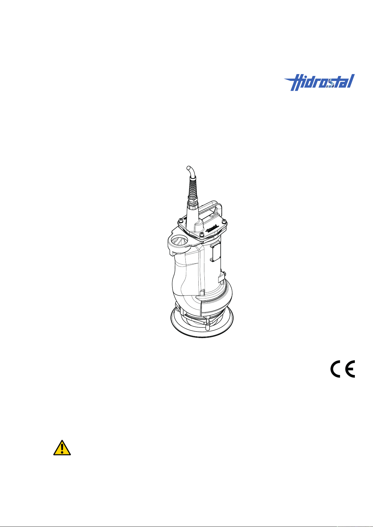
Instructions
Compact pump A2Q, BN2, BE2, BN3, BK3
13-BA8057 EN
Translation of the original instructions
Before starting work, read these instructions!
Page 2

Hidrostal AG
Gigering 27
8213 Neunkirch
Switzerland
T +41 (0) 52 687 06 87
F +41 (0) 52 681 20 84
www.hidrostal.ch
Revision status151130
This manual is protected by copyright and is exclusively for internal
purposes.Transfer of this manual to third parties, reproductions in any
manner and form – in full or in part – as well as exploitation and/or
communication of content without written permission from the manufacturer,
except for internal purposes, is prohibited.
Page 3

Table of contents
Table of contents
1 General information .................................................................................................................................5
1.1 Information about these instructions................................................................................................... 5
1.2 Explanation of symbols....................................................................................................................... 5
1.3 Disclaimer ........................................................................................................................................... 6
1.4 Terms of warranty............................................................................................................................... 7
1.5 Customer service and product monitoring .......................................................................................... 7
1.6 Spare parts ......................................................................................................................................... 7
2 Safety requirements ..................................................................................................................................8
2.1 Introduction ......................................................................................................................................... 8
2.2 Responsibility of the operating company ............................................................................................ 8
2.3 Personnel requirements...................................................................................................................... 9
2.4 Intended use ..................................................................................................................................... 10
2.4.1 Application limits ....................................................................................................................10
2.5 Personal protective equipment ......................................................................................................... 10
2.6 Special hazards ................................................................................................................................ 11
2.6.1 Mechanical hazards ...............................................................................................................11
2.6.2 Biohazards .............................................................................................................................12
2.6.3 Hazards from electric energy .................................................................................................12
2.6.4 Hazards in the working area ..................................................................................................13
2.7 Safety mechanisms and devices, protection against restart, emergency shutdown, what to do in the
event of danger or accidents ............................................................................................................ 13
3 Technical Data .........................................................................................................................................15
3.1 Intended purpose.............................................................................................................................. 15
3.2 General information .......................................................................................................................... 15
3.3 Operating conditions......................................................................................................................... 15
3.4 Consumables.................................................................................................................................... 16
3.4.1 Overview of hydraulic cooling oil............................................................................................ 16
3.5 Type plate ......................................................................................................................................... 16
4 Design and functions ..............................................................................................................................18
4.1 Overview........................................................................................................................................... 18
4.2 Electric motors .................................................................................................................................. 19
4.3 Operational safety components ........................................................................................................ 19
4.4 Hydraulics ......................................................................................................................................... 21
4.5 Connections...................................................................................................................................... 21
4.6 Controls ............................................................................................................................................ 22
5 Transport and storage ............................................................................................................................23
5.1 Transport .......................................................................................................................................... 23
5.1.1 Symbols and information on packaging .................................................................................23
5.1.2 Packages with anchor points .................................................................................................24
5.1.3 Pallet transport by forklift .......................................................................................................24
5.1.4 Pallet transport by crane ........................................................................................................25
Hidrostal AG iii / 49
Page 4

Table of contents
5.1.5 Crane transport of unpacked pump .......................................................................................25
5.2 Storage ............................................................................................................................................. 25
6 Installation and initial commissioning ..................................................................................................27
7 Operation and special operation............................................................................................................28
7.1 Pumping the sump dry...................................................................................................................... 28
8 Maintenance.............................................................................................................................................29
8.1 Maintenance schedule...................................................................................................................... 29
8.2 Service connections and inspection openings.................................................................................. 30
8.3 Tightening torque for greased screw thread ..................................................................................... 31
8.4 Maintenance work............................................................................................................................. 31
8.4.1 Preparation tasks for maintenance ........................................................................................31
8.4.2 Visual inspection ....................................................................................................................31
8.4.3 Check/readjust impeller clearance......................................................................................... 32
8.4.4 Checking the oil .....................................................................................................................35
8.4.5 Replacing the pump ...............................................................................................................37
8.5 Measures after completion of work................................................................................................... 40
9 Faults ........................................................................................................................................................41
9.1 Safety................................................................................................................................................ 41
9.2 Fault table ......................................................................................................................................... 42
9.3 Measures after completion of work................................................................................................... 45
10 Disassembly.............................................................................................................................................47
10.1 Safety................................................................................................................................................ 47
10.2 Disassembly ..................................................................................................................................... 47
10.3 Disposal ............................................................................................................................................ 48
11 Appendix ..................................................................................................................................................49
iv / 49 Hidrostal AG
Page 5

General information | 1
1 General information
1.1 Information about these instructions
Target group The target group of these operating instructions is the pump operating
company once the system, in which the pump is fitted, has been handed
over by the system manufacturer to the operating company in ready-for-use
condition.
The selection of the suitable pump, the safe and correct integration into the
system, the description of the operation, the installation and commissioning
are the system manufacturer's responsibility and are NOT covered in these
operating instructions.
How to use these operating
instructions
Reading obligation Before starting any task, personnel must carefully read and understand this
Storage location These instructions are part of the machine and must be stored in an easily
Resale If the machine is sold or transferred, the operating instructions must also be
Other applicable
documents, regulations
and directives
Illustrations in these
instructions
Loss of the operating
instructions
These operating instructions contribute to the safe and efficient handling of
the machine. The fundamental prerequisite for safe working is the
adherence to all safety information, warnings and operating instructions
given in the manual.
manual.
accessible location for personnel to consult before starting work.
passed on to the new owner.
Besides these operating instructions, the instructions and information as well
as the signs on the machine also apply. Any advice on technical
modifications must be attached to these instructions. Furthermore, the local
accident prevention regulations and general safety regulations for the
application range of the machine apply.
Illustrations in these instructions are provided for general understanding and
may differ from the actual design of the machine.
If these operating instructions are lost, please order replacement
immediately (delivery against a nominal charge). Contact data see Imprint
[▶2].
1.2 Explanation of symbols
Symbols are used to denote safety notes and warning messages in these
instructions. Signal words are found at the start of the safety notes and
warning messages and are used to express the severity of the hazard.
Safety instructions must be observed and proper care must be taken to
avoid accidents or injury and damage to property.
DANGER
... indicates an imminent dangerous situation that will result in death or
serious injuries if not prevented.
Hidrostal AG 5 / 49
Page 6

1 | General information
WARNING
... indicates a potentially dangerous situation that could result in death or
serious injuries.
CAUTION
... indicates a potentially dangerous situation that could result in minor
injuries.
NOTICE
... indicates a potentially dangerous situation that could result in damage to
property.
NOTE
... indicates helpful advise and recommendations as well as information for
efficient and trouble-free operation.
1.3 Disclaimer
Information in these
instructions
Supply, delivery Beyond the contractually negotiated obligations, the General Terms &
Technical changes The publication date of these operating instructions applies. Hidrostal AG
Disclaimer The manufacturer excludes liability for damage and accidents related to the
The information and safety warnings in these instructions of use have been
composed with regard to the applicable standards, directives and
regulations, the state of technology and our years of experience.
Due to the optional equipment, production of custom models or technical
changes reflecting technological improvements, the scope of delivery and
the execution of the machine can deviate from the descriptions and
depictions contained herein.
Conditions and delivery terms of the supplier also apply. These are subject
to the applicable laws at the time of signing of the contract.
reserves the right to make technical changes to the machine as part of
redevelopment to improve its safety and functionality.
following points:
• Non-intended use of the machine
• Non-compliance with the information and warnings given in these
operating instructions
• Work on, or with the machine, by unqualified or unauthorised personnel
• Installation of non-genuine spare parts
• Unauthorised modifications without the written approval from the
manufacturer
• Use of unauthorised operating materials
6 / 49 Hidrostal AG
Page 7
General information | 1
1.4 Terms of warranty
Location The terms and conditions can be found in the purchase agreement and the
supplier's General Terms & Conditions.
Fundamentals The supplier will make final decisions on claims following the return or return
shipment of all defective components, or following an on-sight inspection if
necessary. The replacement of defective parts does not extend the warranty
period of the machine. Modifications or significant repairs by the operating
company or third parties undertaken without the written consent of the
supplier void the warranty.
1.5 Customer service and product monitoring
Customer service Our customer service department is available in the event of problems or if
questions arise that cannot be resolved solely through this user manual, as
well as for technical queries. For contact data, see Imprint [▶2].
Product monitoring In our efforts to constantly improve our product, we in the Customer Service
department are interested in hearing about your experiences in working with
the machine.
Please inform us of any problems or errors that you may have encountered
while handling the machine. Please notify the manufacturer of any accidents
or hazardous incidents.
1.6 Spare parts
Spare parts shall be obtained from an authorised dealer or directly from
manufacturer. Contact data see Imprint [▶2].
When using non-approved spare parts, all claims concerning warranty,
service, damage and/or liability against manufacturer or his agents, dealers
and representatives will be forfeited.
NOTE
When making spare parts enquiries or placing spare parts orders, complete
information must be provided such as Type designation in the contract. The
spare parts list can be found in Appendix [▶49].
Hidrostal AG 7 / 49
Page 8

2 | Safety requirements
2 Safety requirements
2.1 Introduction
This section provides an overview of all key safety aspects for optimum
safety of personnel, as well as safe and highly reliable operation.
Non-compliance with the operating instructions as well as the safety
information and warnings listed in this manual can result in considerable
risks.
These operating instructions can only include the risks that have been
identified on the basis of a risk assessment. Risks that occur due to working
conditions, the location of the machine and the interfaces with external
components must be determined and the safety instructions amended
accordingly.
2.2 Responsibility of the operating company
Definition of terms The term “operating company” as used in these instructions refers to the
company or its management that procures the machine (purchase, lease,
rent, etc.) and assigns personnel with the task of handling the machine
(transportation, installation, operation, maintenance, etc.).
Fundamentals Since the machine is intended for use in a commercial environment, the
operating company is strictly subject to the statutory requirements governing
safety at the workplace. In addition to the safety warnings in these operating
instructions, the safety, accident prevention and environmental protection
regulations governing the location where the machine is to be used are also
applicable.
Risk assessment The operating company must inform themselves about the applicable
occupational safety regulations. A risk assessment must also be carried out
to identify additional risks resulting from the specific working conditions at
the location of operation.
Operating Instructions According to the results of the risk assessment of the workplace, the
operating company must initiate, implement and document the operating
instructions. The operating company is responsible for ensuring that these
operating instructions are kept up to date with the current legal requirements
for the entire service life of the machine.
Responsibilities The operating company must manage the responsibilities for work on or with
the machine, including naming a party to be responsible for the safe
operation of the machine and coordinating all tasks.
Information flow The operating company must ensure that all personnel who carry out work
on or with the machine have read and understood these and other
supplementary operating instructions.
Personal protective
equipment
The operating company must provide operating personnel with the
necessary personal protective equipment.
8 / 49 Hidrostal AG
Page 9
Safety requirements | 2
Safety requirements Where applicable, before commissioning, the operating company must make
sure that the machine into which this product is to be installed, or of which it
represents a component, corresponds to the fundamental safety
requirements and stipulations of all relevant directives.
Technically flawless
condition
To keep the machine in a technically flawless condition at all times, the
operating company must ensure that the maintenance intervals prescribed in
these operating instructions are complied with. The operating company must
furthermore ensure that all necessary safety mechanisms and devices are
properly installed on the machine. The safety mechanisms and devices must
be inspected regularly to check that they are all present and functioning
properly.
2.3 Personnel requirements
General information As personnel, the only authorised persons are those who carry out their task
reliably and whose responses are not impaired, e.g. by drugs, alcohol or
medication.
When selecting personnel, observe the applicable job-specific age
regulations applicable at the location of operation of the machine.
WARNING
Incorrect operation because of insufficient qualifications and knowledge.
Unauthorised persons who do not satisfy the conditions stated here are
unable to recognise the risks in the areas of operation.
Risk of severe injury!
• All tasks may only be carried out by suitably qualified personnel.
• Keep unauthorised personnel away from the danger areas.
In the operating instructions, the qualifications for the various tasks are
specified as follows:
Trained personnel Trained personnel have the technical education, know-how and experience
as well as the knowledge of applicable standards and regulations that allow
them to execute the work assigned to them and to independently recognise
and avoid potential dangers.
Trained personnel are also trained by Hidrostal or a Hidrostal sales partner
in how to operate the pump. The completion of training programs must be
documented.
Manufacturer (service
centre)
Qualified electricians Qualified electricians possess the technical education, knowledge and
Only trained Hidrostal personnel or trained personnel of a Hidrostal sales
partner are allowed to carry out service work. Nobody else is allowed to
perform this work. To have the required work performed, please contact our
Service department, see Imprint [▶2].
experience as well as knowledge of applicable standards and regulations
that allow them to execute work on electrical equipment and to
independently recognise and avoid potential dangers.
Qualified electricians are trained for the specific site where they work and
know the relevant directives, standards and specifications.
Hidrostal AG 9 / 49
Page 10
2 | Safety requirements
Forklift drivers Forklift drivers must be at least 18years old and their physical, mental state
and personal characteristics must be such that they are capable of driving a
forklift either in seated or standing position.
Furthermore, forklift drivers must have received training in how to operate a
forklift in seated or standing position.
Forklift drivers must have demonstrated to the operating company their
ability to operate a forklift in a seated or standing position and have been
instructed in writing by the operator to do so.
Hoisting equipment
operators
Instructed persons
(operators)
Hoisting equipment operators have been trained and authorised to perform
this work.
Instructed persons have been informed by trained personnel about the
assigned tasks and possible hazards in case of incorrect behaviour. The
completion of training programs should be documented.
2.4 Intended use
The pump is exclusively intended for pumping liquids and viscous, noncombustible media.
If extremely abrasive or aggressive media are circulated, the pump must be
designed in resistant material.
Pumps of the types A2QR2, A2QR4, A2QS2, A2QS4, A2QE4, BE2, and
BK3 can be operated when they are immersed or when they are
permanently outside the liquid. The types A2QE2, BN2, and BN3 must
always be immersed during operation (exception see chapter Pumping the
sump dry [▶28]).
The pump must be kept in a clean and sound condition and its construction
may not be altered from its delivered state.
Intended use also includes compliance with all information contained in
these operating instructions.
Any use beyond the one intended, or other use of the machine is regarded
as misuse and can result in dangerous situations.
2.4.1 Application limits
No potentially explosive atmosphere
WARNING
Potentially explosive atmospheres.
Risk of fatal injury!
• Potentially explosive atmospheres in the pump interior or the ambient
environment are NOT permissible.
2.5 Personal protective equipment
Some tasks require personal protective equipment to be worn.
10 / 49 Hidrostal AG
Page 11
In addition to the personal protective equipment specified in these operating
instructions, also observe the warnings located in the work area.
2.6 Special hazards
The following section indicates residual risks determined by a risk
assessment.
• The safety instructions listed here and the warnings in the following
chapters of these instructions must be observed in order to reduce health
hazards and avoid dangerous situations.
2.6.1 Mechanical hazards
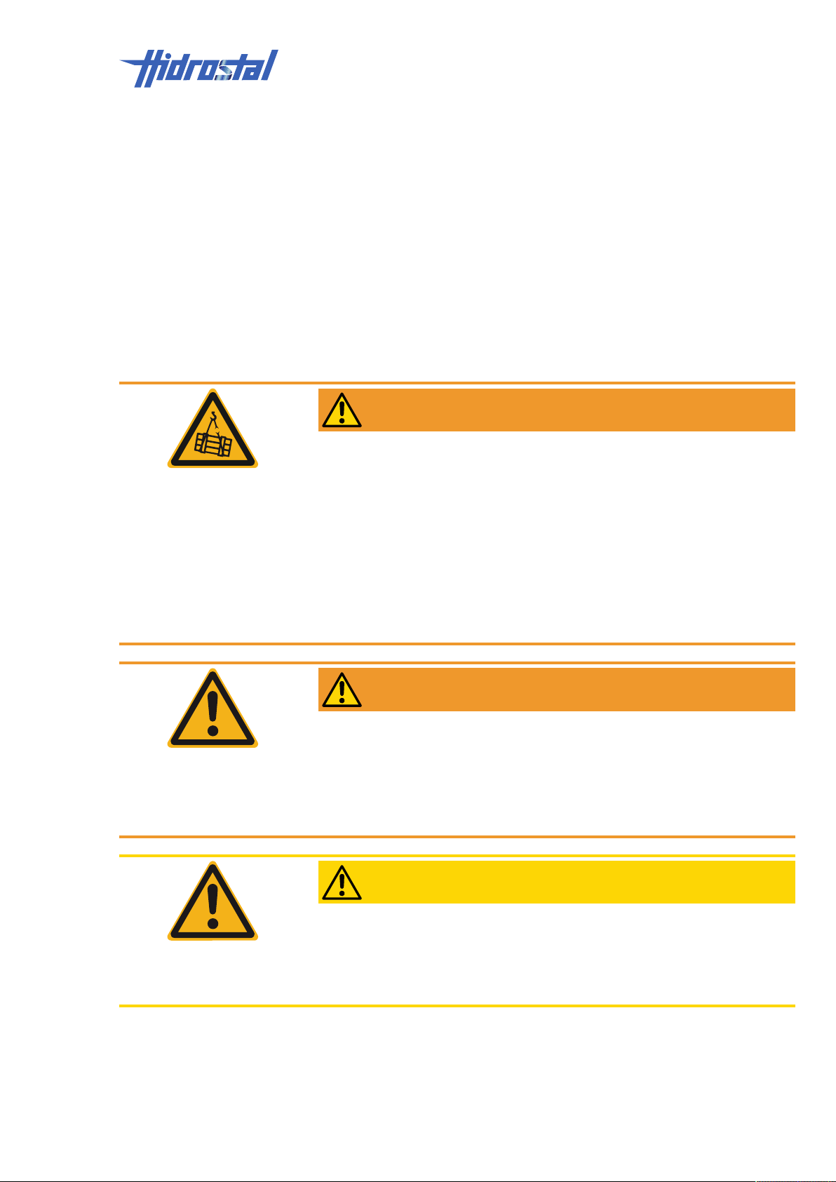
WARNING
Suspended loads.
Suspension points weakened by corrosion and/or mechanical stress.
Risk of fatal injury!
• Use suitable, undamaged hoisting equipment only.
• If there is a suspicion of weakened suspension points, secure the load
with suitable sling gear.
• Only move loads under supervision.
• Never stand below suspended loads.
• Before leaving the work area: bring the load to the ground.
Safety requirements | 2
WARNING
Tipping loads.
Risk of severe injury!
• Always sufficiently secure components against tipping.
• Use suitable, undamaged hoisting equipment only.
• Only move loads under supervision.
CAUTION
Sharp edges on the edge and inside the pump chamber.
Risk of injury!
• Proceed carefully when working in the vicinity of sharp edges.
• Wear safety gloves.
Hidrostal AG 11 / 49
Page 12
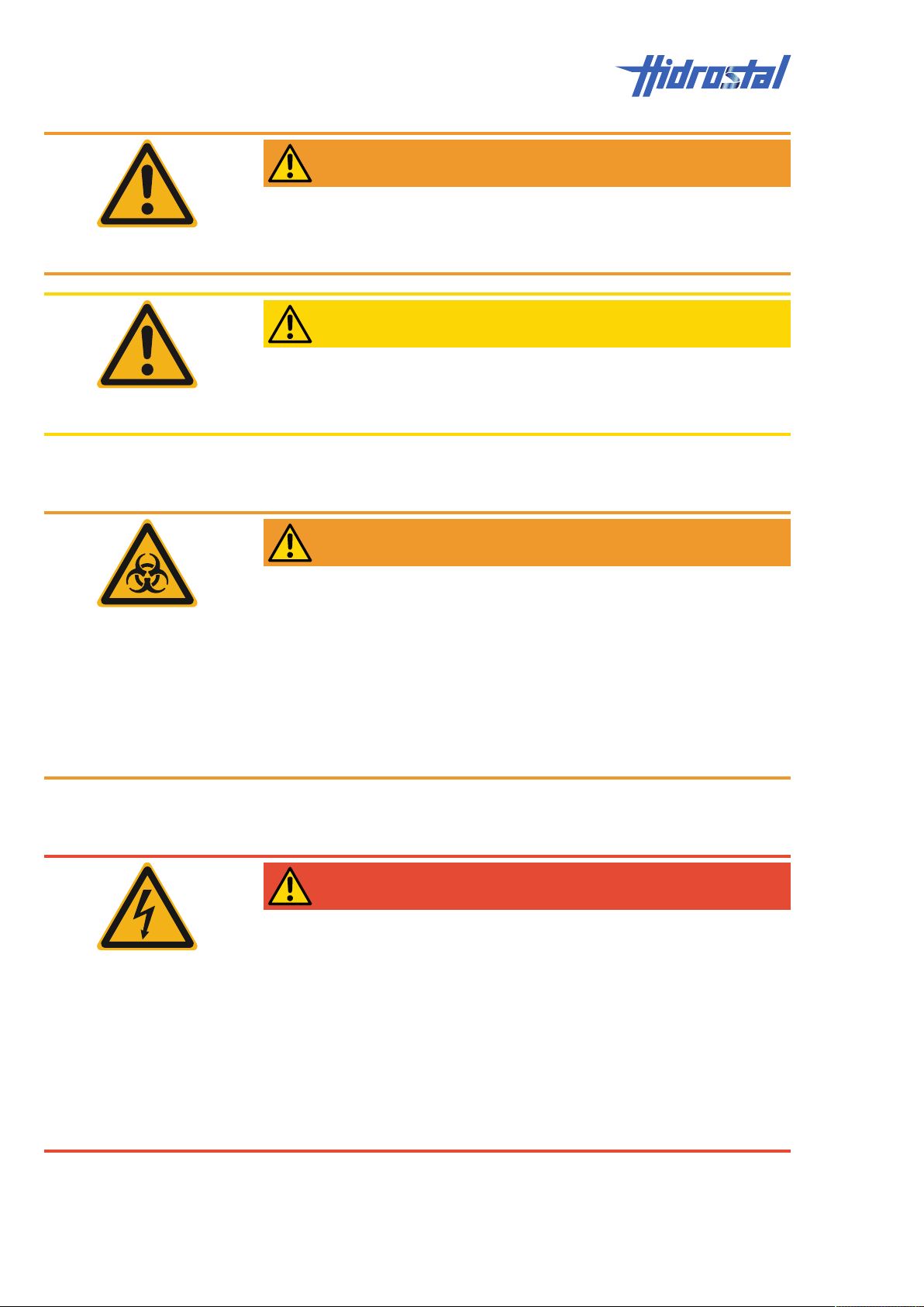
2 | Safety requirements
WARNING
Flying parts when cleaning with a high-pressure cleaner.
Risk of severe injury!
• Wear safety goggles.
CAUTION
Wood splinters and nails on packaging material.
Risk of injury!
• Wear safety gloves.
2.6.2 Biohazards
WARNING
Contact with infectious substances.
Risk of severe illness!
• Obtain binding information about the hazards relating to the medium from
the operator of the plant.
• Wear personal protective equipment.
• Thoroughly clean the pump.
• Carefully dispose of liquid drained from the oil chamber.
• Thoroughly clean tools after use.
2.6.3 Hazards from electric energy
DANGER
Contact with live parts.
Damaged cable insulation
Risk of fatal injury!
• In case of damaged insulation, disconnect the power supply immediately
and have it repaired.
• Before connecting the machine to the power supply, compare the
specifications Type plate [▶16] with those of the grid and only connect
if they are identical.
• Any work on the electrical system must be performed by authorised
electricians.
12 / 49 Hidrostal AG
Page 13
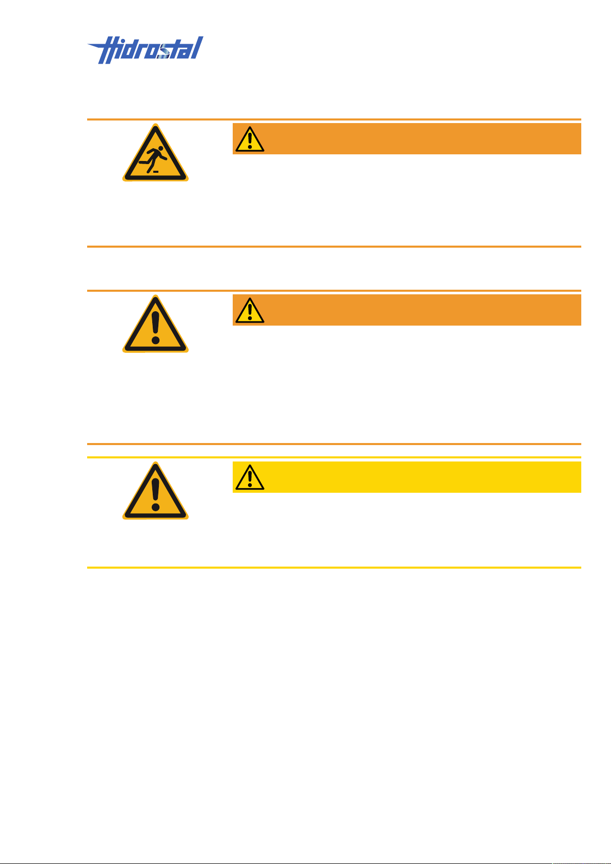
2.6.4 Hazards in the working area
WARNING
Dirt and items left lying around represent tripping hazards.
Risk of severe injury!
• Always keep the work area clean.
• Remove objects that are no longer required.
• Use black/yellow tape to mark areas where there is a risk of tripping.
For pumps that are operated outside the liquid (A2QR2, A2QR4, A2QS2,
A2QS4, A2QE4, BE2, BK3):
WARNING
Work at the pump location, noise from neighbouring pumps, tank
overflowing.
Risk of injury!
Risk of permanent health damage!
• Always wear hearing protection near running pumps.
• Before entering a tank, make sure at the control console that the tank will
not be flooded during the work.
Safety requirements | 2
CAUTION
Insufficient lighting in the work area.
Risk of injury!
• Provide adequate lighting at the workplace.
• Immediately replace defective lighting components.
2.7 Safety mechanisms and devices, protection against restart, emergency shutdown, what to do in the event of danger or accidents
The system manufacturer is responsible for ensuring the safety of the
system in which the pump is installed. This aspect is not covered in these
operating instructions.
The system must be fitted with at least a lockable mains switch, to ensure
that all the conductors connected to the pump is voltage free and to prevent
an unintentional restart.
Hidrostal AG 13 / 49
Page 14

2 | Safety requirements
See chapter Operational safety components [▶19] for information on
operational safety components that are either included as standard in the
pump or that are optionally available from the system manufacturer.
14 / 49 Hidrostal AG
Page 15
Technical Data | 3
3 Technical Data
3.1 Intended purpose
No potentially explosive atmosphere
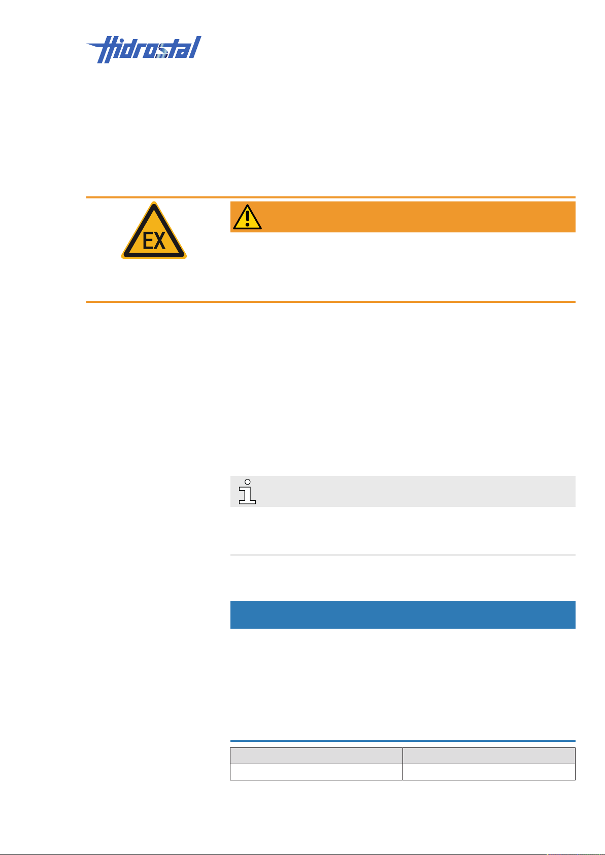
WARNING
Potentially explosive atmospheres.
Risk of fatal injury!
• Potentially explosive atmospheres in the pump interior or the ambient
environment are NOT permissible.
Permissible media The pump is exclusively intended for pumping liquids and viscous, non-
combustible media.
If extremely abrasive or aggressive media are circulated, the pump must be
designed in resistant material.
Pumps of the types A2QR2, A2QR4, A2QS2, A2QS4, A2QE4, BE2, and
BK3 can be operated when they are immersed or when they are
permanently outside the liquid. The types A2QE2, BN2, and BN3 must
always be immersed during operation (exception see chapter Pumping the
sump dry [▶28]).
Temperature
3.2 General information
NOTE
For contract-related technical data (dimensions, weights, performance,
connected loads, etc.) refer to enclosed delivery drawings and data sheets,
see chapter Appendix [▶49].
3.3 Operating conditions
NOTICE
Frozen medium inside the pump.
Risk of failure of the pump housing!
• Make sure that the medium inside the pump and the connected hose
lines does not freeze.
• It is particularly important to make sure that the volume behind the
impeller is drained on pumps that are subject to frost (e.g. by blowing out
with compressed air).
Declaration Value
Temperature of medium max. 40°C
Hidrostal AG 15 / 49
Page 16
3 | Technical Data
1
2
3
4 5 6 7
8
9
10
11 12 13
14 15 16
17
18
19 20
Declaration Value
Ambient temperature max. 40°C
Duration The pump is designed for continuous operation (S1 pursuant to EN
60034-1:10/2010).
Installation position The pump can be operated horizontally or vertically.
3.4 Consumables
3.4.1 Overview of hydraulic cooling oil
used by
manufacturer:
alternative oils
recommended
by
manufacturer:
Name Manufacturer Density at 15°C
[kg/m³]
Rinatol 856 Ess+Müller CH-8200
Schaffhausen
Tellus S2 V 15 Shell Oil 872 15 170
Hyspin HVI 15 Castrol 874 15 160
Equivis ZS 15 Total 853 15 174
850 14.2 190
Viscosity at
40°C [mm²/s]
Flash point
COC [°C]
NOTE
Other equivalent mineral oils can also be used. The viscosity at 40°C may
not exceed 15mm²/s and the flash point must never be below 155°C.
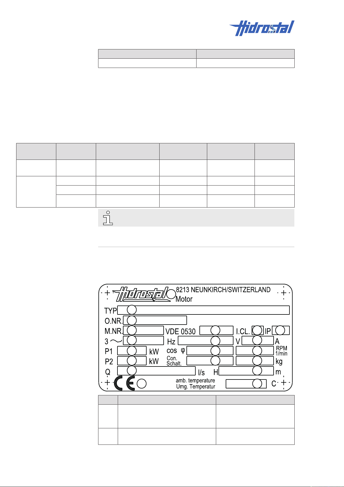
3.5 Type plate
The type plate is located on the motor housing.
16 / 49 Hidrostal AG
Item Declaration Example
1 Manufacturer Hidrostal AG
8213 Neukirch
Switzerland
2 Type C0CQ-RL3 + CNBA2-GSEQ1
+ NW1A2O-10
Page 17
Technical Data | 3
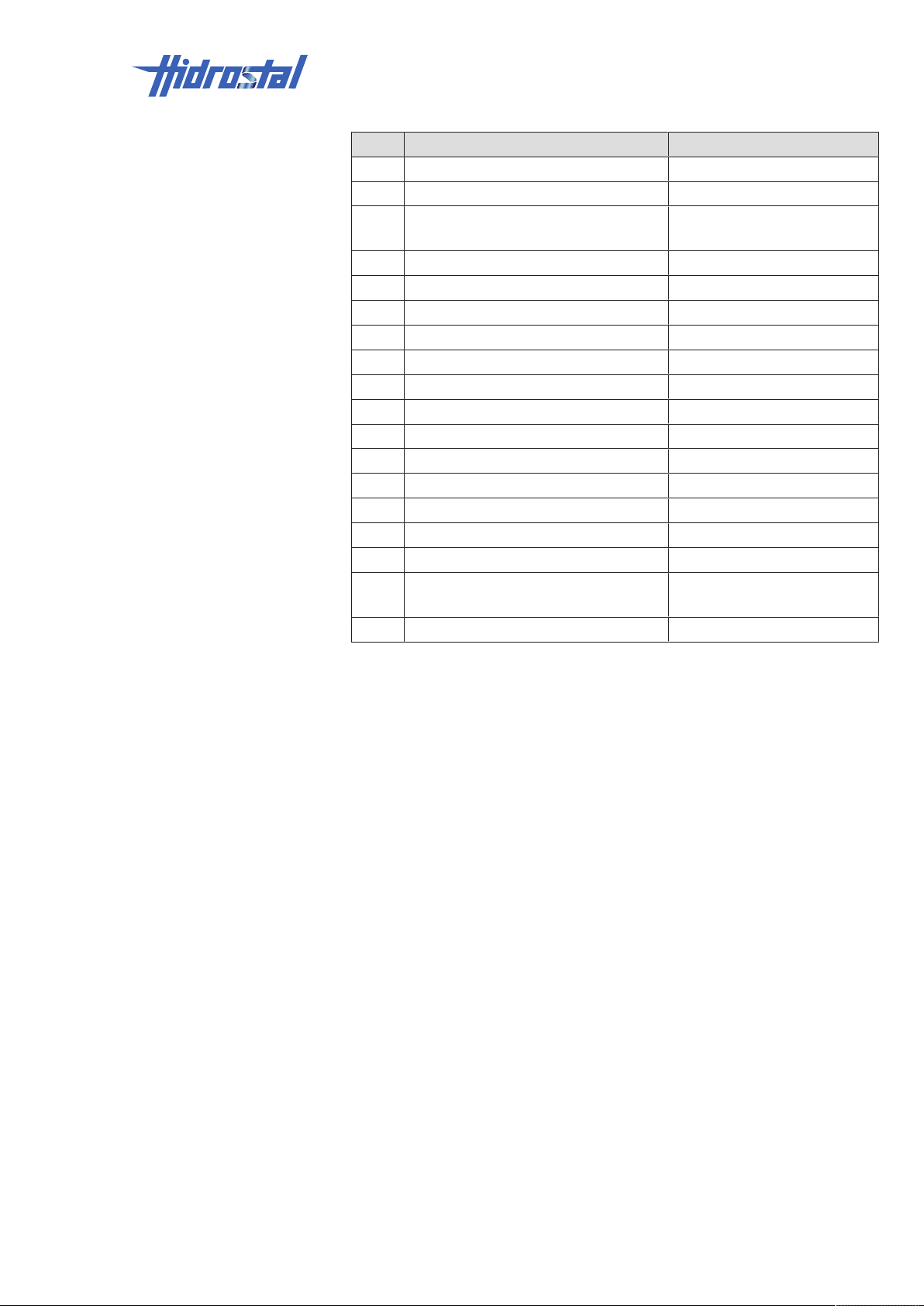
Item Declaration Example
3 Order number 12007807
4 Serial number 212832
5 VDE 0530 (rotating electrical
07/91
machines)
6 Insulation class F
7 Protection classes 68
8 Mains frequency 50Hz
9 Mains voltage 400V
10 Nominal motor current 7.8A
11 Power input kW* (customer data)
12 Power factor 0.88
13 Nominal speed 27901/min
14 Nominal output 3kW
15 Phase sequence Y
16 Weight 66.2 kg
17 Flow rate l/s* (customer data)
18 Delivery height m* (customer data)
19 CE marking see Declaration of Conformity
in the appendix
20 Ambient temperature 40°C
* Fields can remain empty.
Hidrostal AG 17 / 49
Page 18
4 | Design and functions
1
2
3
4
5
6
4 Design and functions
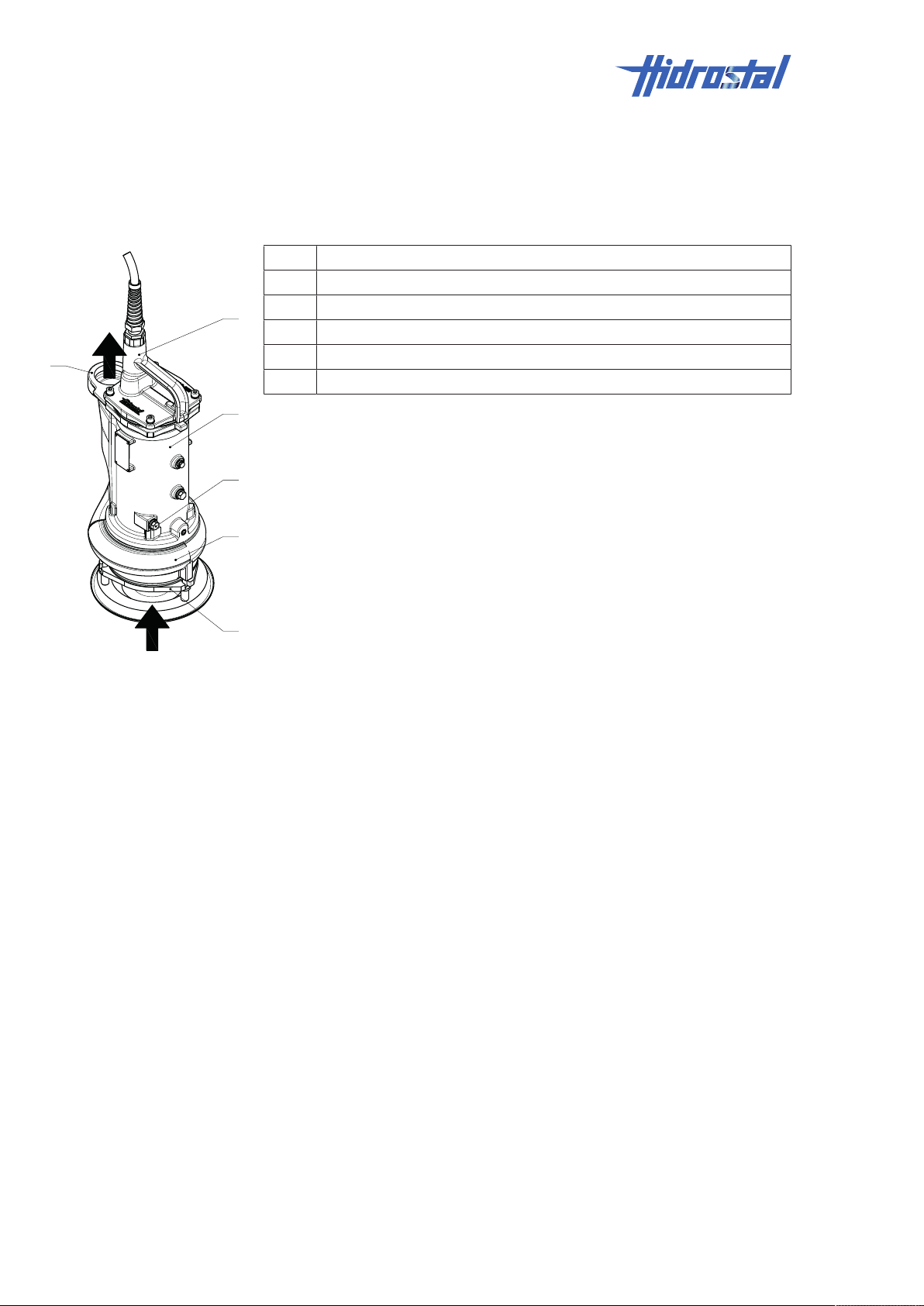
4.1 Overview
1 Cable cover
2 Electric motor
3 Oil chamber
4 Hydraulic part
5 Suction flange
6 Pressure flange
The impeller of the hydraulic part (3) sucks in the conveyed medium via the
suction flange (4) and conveys it to the pressure flange (5).
18 / 49 Hidrostal AG
Page 19
4.2 Electric motors
3
1
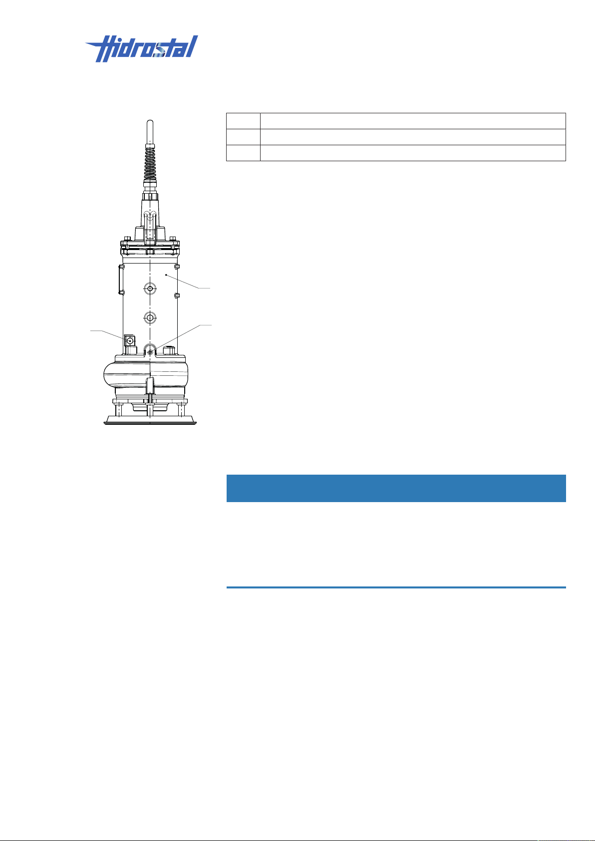
2
1 Stator housing
2 Opening to drain, fill in, and test the oil
3 Flushing port to remove obstructions from behind the impeller
The pump is equipped with a submersible motor that is installed in the pump
sump.
Pumps of the types A2QR2, A2QR4, A2QS2, A2QS4, A2QE4, BE2, and
BK3 can be operated when they are immersed or when they are
permanently outside the liquid. The types A2QE2, BN2, and BN3 must
always be immersed during operation (exception see chapter Pumping the
sump dry [▶28]).
Design and functions | 4
4.3 Operational safety components
NOTICE
Incorrect design of system control.
Bypassing of safety components.
Risk of damage to property!
• ALL of the safety components below will only function correctly if the
system control analyses them correctly.
The following components can be installed:
Hidrostal AG 19 / 49
Page 20
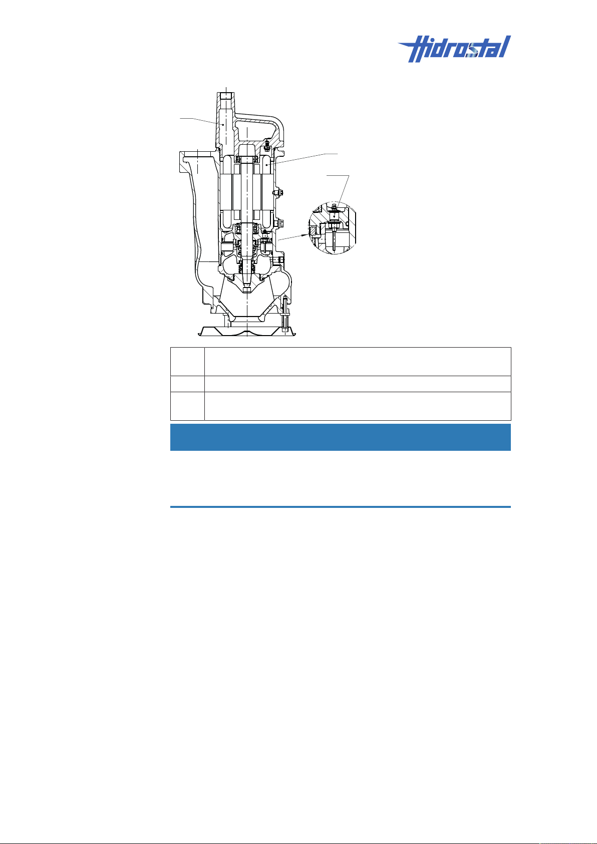
4 | Design and functions
1
2
3
Temperature monitoring:
Bimetal switch or PTC
probe:
1 Coil head with integrated temperature limiter (bimetal switch or PTC
probe, option)
2 Moisture sensor (BN3, BK3 only; option)
3 Temperature limiter installed in the cable cover (bimetal 80°C, not
available for A2Q)
NOTICE
Improper electrical connection.
Risk of damage to property!
• Never connect a PTC probe to more than 2.5V.
Temperature monitoring sensors protect the electric motor winding against
excessive temperatures. Bimetal switches (NC) and thermistors (PTC) are
used. In contrast to bimetal switches, thermistors are still able to protect the
electric motor when the rotor is blocked and start-up is sluggish.
Three 150°C bimetal switches are installed in the top coil head and
connected in series. The top coil head also holds three 150°C thermistors
connected in series. Each phase has one sensor of each kind. Depending
on the configuration, the connection cables of the sensors are provided via
the control cables.
The temperature monitoring sensors, such as the bimetal switches or
thermistors, always need to be evaluated by the electronic evaluation
system. Bimetal switches can be connected to a certified electronic
evaluation system or directly to the control unit (max. 250VAC, 2.5A).
Thermistors must only be operated and evaluated with a certified electronic
evaluation system. Thermistors always need to be employed for temperature
monitoring during frequency converter operation. In this case, they can be
directly connected to the frequency converter.
20 / 49 Hidrostal AG
Page 21
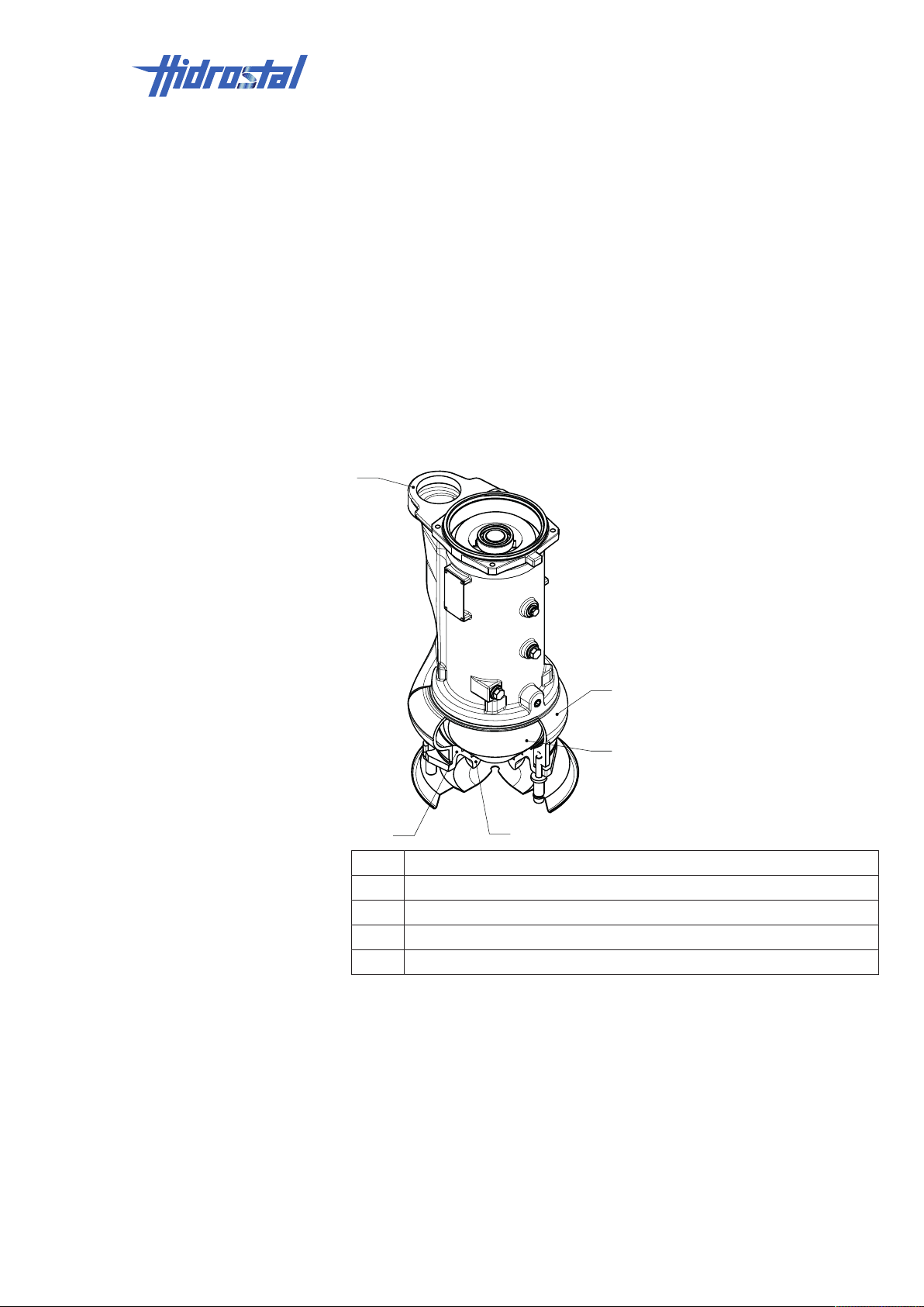
Moisture sensor (BN3, BK3
1
5
2
4
3
only; option):
4.4 Hydraulics
Design and functions | 4
The following conditions must then be adhered to: When the temperature
limiter responds, the pump must switch off immediately and must NOT start
again automatically after cooling down. Before the pump is started up again,
the cause must be investigated and the fault(s) eliminated, noting that
repairs may only be performed by authorised trained personnel.
The moisture sensor monitors the seal at the medium side for leakage. The
sensor and the electronic evaluation system measure the electrical
resistance of the sealing medium. The resistance decreases as the water
content in the sealing medium increases. The electronic evaluation system
can trigger an alarm when a value of 60kOhm is reached. These sensors
can be evaluated to provide additional pump protection, and to initiate a
precautionary shutdown.
1 Suction cone
2 Screw centrifugal impeller (impeller)
3 Pressure flange
4 Spiral casing
5 Suction flange
4.5 Connections
The pump is connected to the energy supply by means of one or more
electrical cables. See Appendix [▶49] for the wiring diagram.
The design and documentation of the system's internal connections are the
responsibility of the system manufacturer and are not covered in these
Hidrostal AG 21 / 49
operating instructions.
Page 22

4 | Design and functions
4.6 Controls
NOTE
The device has no separate controls. A system control is used for operation.
The control unit is not part of these operating instructions.
22 / 49 Hidrostal AG
Page 23
5 Transport and storage
The system manufacturer is responsible for transporting the pump as part of
the machine construction or modernisation. The system manufacturer
provides the company operating with a turnkey system.
This chapter focuses on the transport and storage of replacement pumps.
5.1 Transport
WARNING
Unsafe behaviour.
Incorrect operation because of insufficient qualifications and knowledge.
Risk of severe injury!
• Observe the information and personnel requirements in chapter Safety
requirements [▶8].
Transport and storage | 5
5.1.1 Symbols and information on packaging
Depending on its size and shape, the transport container is suitable for
transport by forklift or by crane.
Weight specifications can either be found on the outside of the packaging or
on the pump's type plate, depending on the type of packaging used.
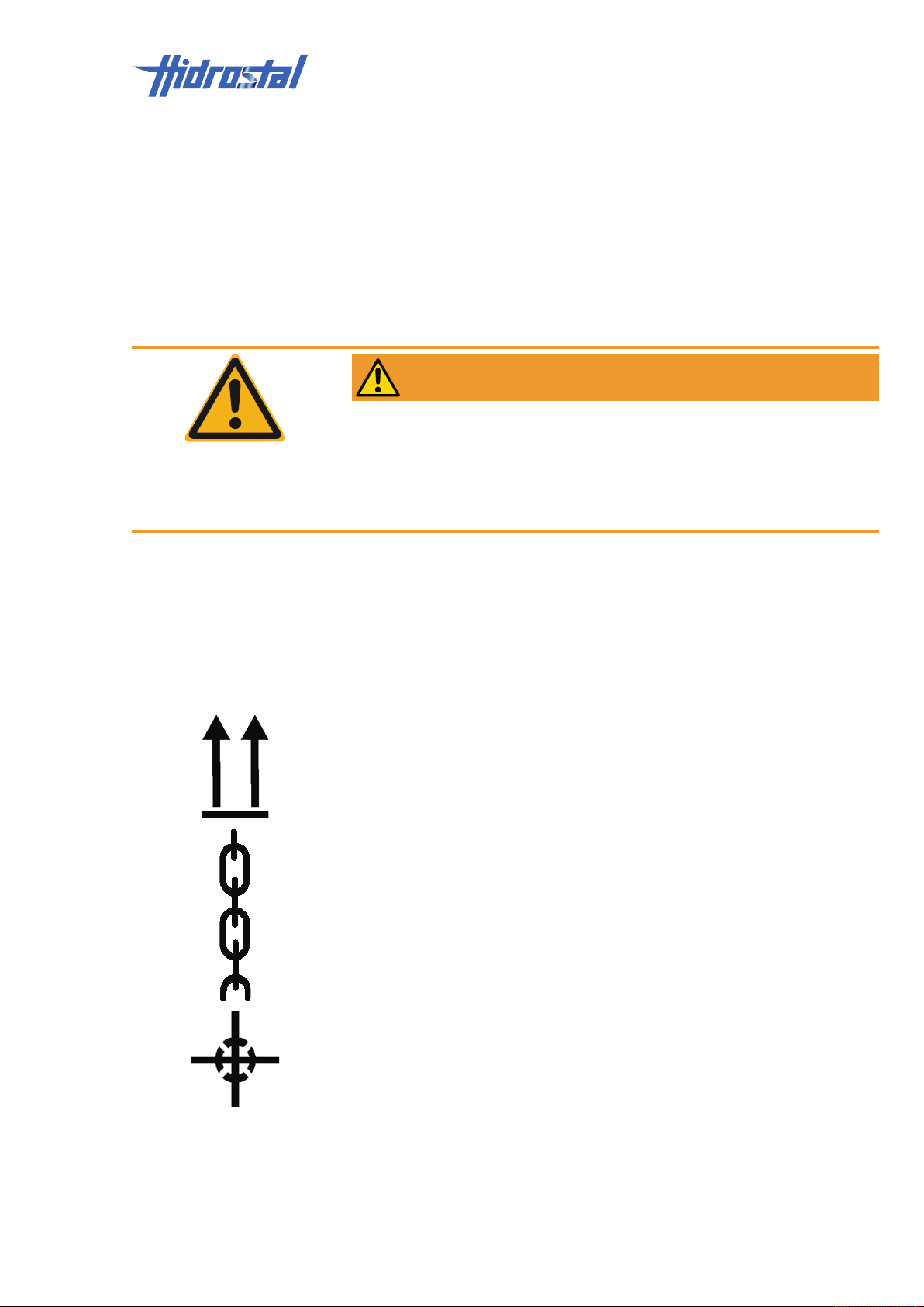
• Observe the symbols and information on the packaging.
The arrows indicate the top side of the package. They must always point
upwards, otherwise the contents can be damaged.
• Only attach sling gear (chains, hoisting straps) at the points designated
with this symbol.
Shows the centre of gravity of a package.
• The centre of gravity must be taken into account during lifting and
transport.
Hidrostal AG 23 / 49
Page 24

5 | Transport and storage
• Protect the packaging against water and keep dry.
Indicates packages that cannot be stacked.
5.1.2 Packages with anchor points
Packages which have anchor points can be transported directly by crane
under the following conditions:
• The crane and lifting gear must be designed for the weight of the
transported item.
• The operator must be authorised to operate the crane.
Protective equipment:
• Hard hat
1. Fasten belts or multiple-point suspension gear appropriately.
2. Make sure that the transported item is hanging straight, check if the
package has an off-centre centre of gravity.
3. Start the transport.
5.1.3 Pallet transport by forklift
Packages that are fastened on pallets can be transported by forklift under
the following conditions:
• The forklift must be designed for the weight of the transported item.
• The transported item must be securely fastened to the pallet.
Personnel:
• Forklift drivers
1. Drive the forklift with the forks in between the pallet deck-boards.
2. Drive the forks in far enough that they protrude on the opposite side.
3. Ensure that the pallet cannot tip as a result of an off-centre centre of
gravity.
4. Lift the pallet with the transported item and start the transport.
24 / 49 Hidrostal AG
Page 25
Transport and storage | 5
5.1.4 Pallet transport by crane
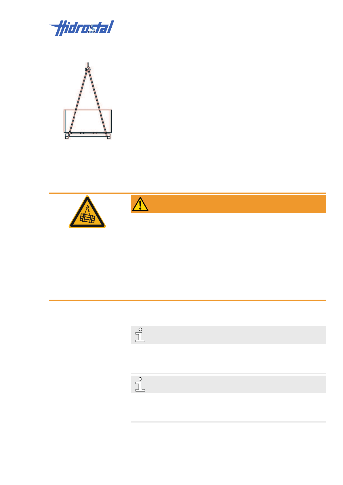
Packages that are fastened on pallets can be transported by crane under the
following conditions:
• The crane and lifting gear must be designed for the weight of the
transported item.
• The operator must be authorised to operate the crane.
1. Fasten belts or multiple-point suspension gear onto the pallet
appropriately and protect the pallet from slipping.
2. Check that the transported items are not damaged by the fastening
equipment. If necessary, use other fastening equipment.
3. Ensure that the pallet cannot tip as a result of an off-centre centre of
gravity.
4. Start the transport.
5.1.5 Crane transport of unpacked pump
WARNING
Suspended loads.
Suspension points weakened by corrosion and/or mechanical stress.
Risk of fatal injury!
• Use suitable, undamaged hoisting equipment only.
• If there is a suspicion of weakened suspension points, secure the load
with suitable sling gear.
• Only move loads under supervision.
• Never stand below suspended loads.
• Before leaving the work area: bring the load to the ground.
5.2 Storage
NOTE
The delivery documents provided with the pump include important
information on the permissible installation position of the pump.
• Store the delivery documents or copies of them together with the pump.
NOTE
The transport packaging also protects the pump during storage.
The transport packaging of a replacement pump can be used to return a
defective pump.
Pump storage Store the pump under the following conditions:
• Do not store outdoors.
Hidrostal AG 25 / 49
Page 26
5 | Transport and storage
• Keep dry and dust-free.
• Do not expose to aggressive media.
• Do not expose to any mechanical agitations and vibrations.
• Turn the shaft of the impeller via the front screw every two weeks to
prevent any storage damage. If it cannot be turned in the packaging,
remove the pump from the packaging and re-pack it once it has been
turned.
• Storage temperature: –10…+40°C.
• Relative humidity: max. 60%.
• If storage exceeds 3months, check general condition of all parts and of
packaging at regular intervals.
• Prevent the cable ends from coming into contact with water, as capillary
action will cause the water to flow into the cables.
NOTICE
Frozen liquid inside an already used pump.
Risk of failure of the pump housing!
ü Before putting a used pump into storage:
• Make sure that the oil is free from water, see chapter Checking the oil
[▶35].
• Ensure there is no water in any of the hollow parts of the pump.
NOTE
It is possible that the packages contain storage instructions that go beyond
the requirements mentioned here. Please follow them.
26 / 49 Hidrostal AG
Page 27

Installation and initial commissioning | 6
6 Installation and initial
commissioning
The system manufacturer is responsible for the installation and initial startup
of the pump as part of system construction or modernization. The system
manufacturer hands over an operational system to the company operating
the plant. Installation and initial startup are thus not included in these
operating instructions.
Chapter Replacing the pump [▶37] explains how to replace a defective
pump with a replacement pump.
Hidrostal AG 27 / 49
Page 28
7 | Operation and special operation
7 Operation and special operation
7.1 Pumping the sump dry
The pump has no separate controls.
The pump is switched on and off and monitored by the control for the system
into which the pump is integrated.
The system control is not covered in these operating instructions.
NOTE
The restrictions specified below only apply to pumps of the types A2QE2,
BN2, and BN3. These pumps must always be submerged during operation.
Pumps of the types A2QR2, A2QR4, A2QS2, A2QS4, A2QE4, BE2, and
BK3 can be operated when they are immersed or when they are
permanently outside the liquid. They are NOT subject to the restrictions
specified below.
If the pump sump has to be pumped dry for cleaning, servicing etc., the
submersible motor has to surface and thus loses its cooling. This type of
operation has to be limited to a specific time and monitored carefully.
The maximum operating time with reduced cooling depends on the hydraulic
load, the ambient and medium temperature, and the speed at which the
pump surfaces.
10minutes are considered as a guide value for the maximum permissible
operating time of a surfaced pump at nominal output and 40°C ambient
temperature.
2minutes are considered as a guide value for the minimum cooling time
required between the time of complete immersion and the earliest
permissible restart.
28 / 49 Hidrostal AG
Page 29
Maintenance | 8
8 Maintenance
WARNING
Unsafe behaviour.
Incorrect operation because of insufficient qualifications and knowledge.
Risk of severe injury!
• Observe the information and personnel requirements in chapter Safety
requirements [▶8].
WARNING
Contact with infectious substances.
Risk of severe illness!
• Obtain binding information about the hazards relating to the medium from
the operator of the plant.
• Wear personal protective equipment.
• Thoroughly clean the pump.
• Carefully dispose of liquid drained from the oil chamber.
• Thoroughly clean tools after use.
WARNING
Work at the pump location, noise from neighbouring pumps, tank
overflowing.
Risk of injury!
Risk of permanent health damage!
• Always wear hearing protection near running pumps.
• Before entering a tank, make sure at the control console that the tank will
not be flooded during the work.
8.1 Maintenance schedule
Interval Maintenance work Personnel
initially after approx.
1000oh (operating
hours)
annually Check pump for damage, see chapter Visual inspection
Check pump for damage, see chapter Visual inspection
[▶31]
Check oil level, see chapter Checking the oil [▶35] Trained personnel
[▶31]
Check the electric motor, motor cover, cable inlet and
cable for any damage and resistance-free connection, see
chapter Visual inspection [▶31]
Instructed persons
(operators)
Instructed persons
(operators)
Qualified electricians
Hidrostal AG 29 / 49
Page 30
8 | Maintenance
1
2
3
Interval Maintenance work Personnel
Check oil level, see chapter Checking the oil [▶35] Trained personnel
after circulation of solid
substances, e.g. gravel
Check the impeller clearance, readjust it if necessary. See
chapter Check/readjust impeller clearance [▶32]
Check the impeller clearance, readjust it if necessary. See
chapter Check/readjust impeller clearance [▶32]
Trained personnel
Trained personnel
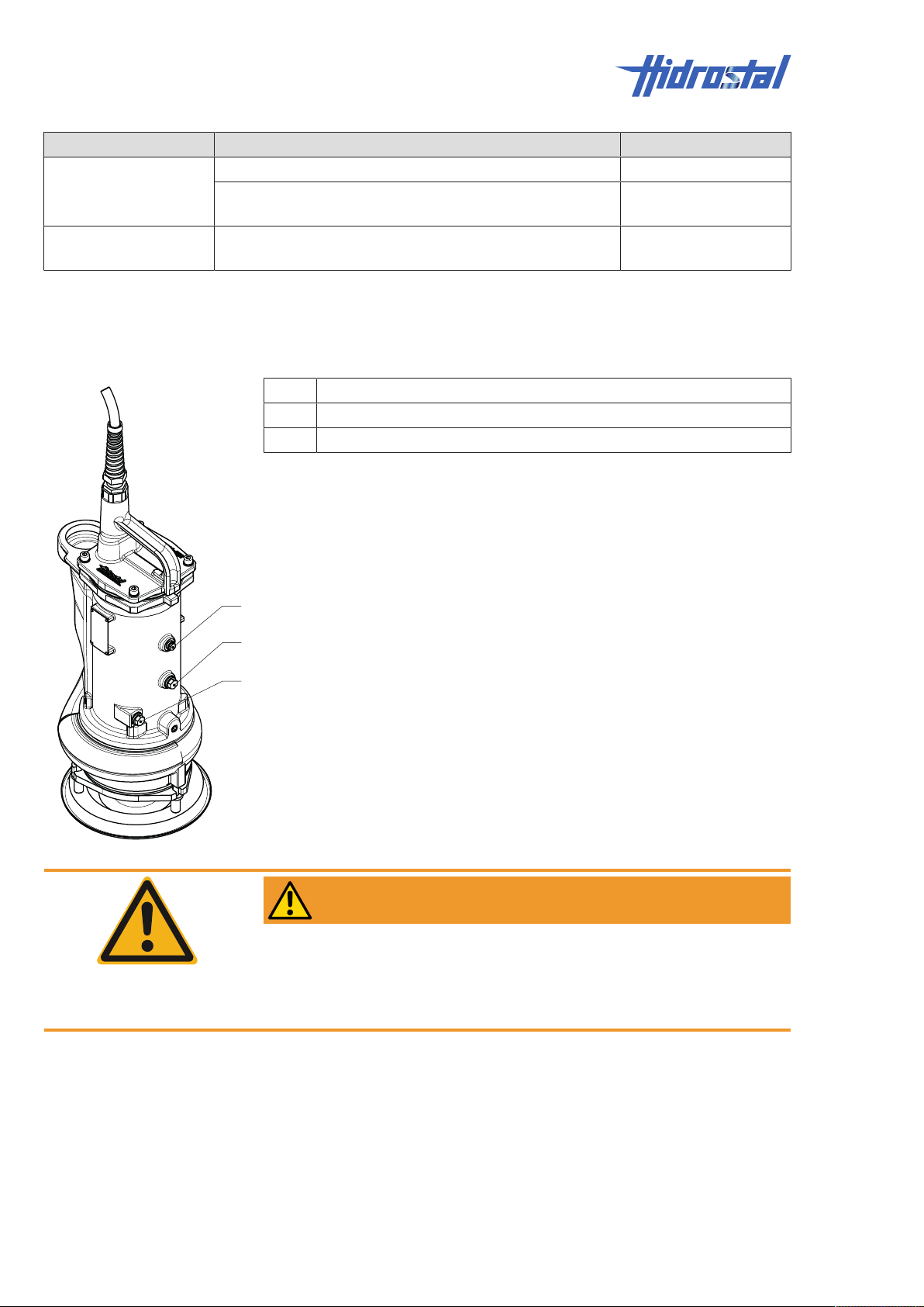
8.2 Service connections and inspection openings
1 Stator winding fastening screw
2 Motor plug, access to the motor chamber
3 Oil chamber
WARNING
Open inspection openings on spiral housing.
Risk of severe injury!
• Inspection openings are only to be opened at complete standstill and with
power supply switched off and protected against restart.
30 / 49 Hidrostal AG
The inspection openings can only be opened with tools. After completion of
work and before restart, the inspection openings must be closed and all
fasteners properly mounted again.
Page 31
Maintenance | 8
8.3 Tightening torque for greased screw thread
Screw thread size Tightening torque for
stainless steel screw
thread A1/A2/A4 [Nm]
M6 7
M8 17.5
M10 35.5
M12 61.5
M16 147
M20 285
M24 310
8.4 Maintenance work
Personal protective equipment:
• Protective clothing
• Protective gloves
• Safety shoes
• Safety goggles
• Hearing protection
8.4.1 Preparation tasks for maintenance
1. Turn off pump or system and protect against restart.
ü If the pump is submerged in the sump:
2. Remove the pump from the sump with suitable lifting gear.
3. Hose down pump with water.
4. Position the pump in a vertical position on a surface and attach lifting
gear on the drive unit to prevent it from tipping.
8.4.2 Visual inspection
8.4.2.1 Pump and motor
Personnel:
• Instructed persons (operators)
1. Check the pump for mechanical damage.
8.4.2.2 Electric motor, motor cover, cable inlet and cable
Personnel:
Hidrostal AG 31 / 49
Page 32
8 | Maintenance
1
3
B
5
4
2
• Qualified electricians
1. Check electric motor, motor cover, cable inlet and cable for visual
damage.
8.4.3 Check/readjust impeller clearance
Personnel:
• Trained personnel
Personal protective equipment:
• Protective clothing
• Safety shoes
Required tool:
• Feeler gauge, thickness gauge
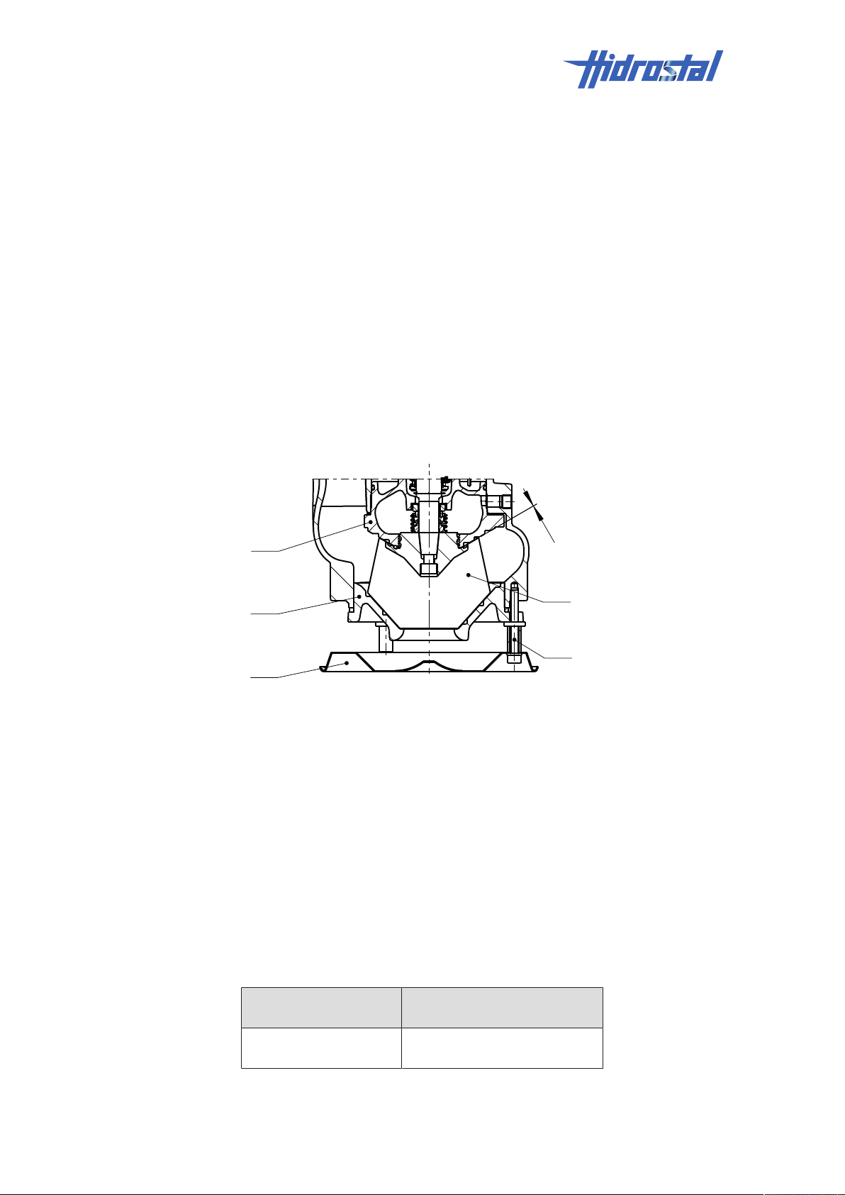
8.4.3.1 Check impeller clearance “B”
Impeller clearance “B” is the gap between impeller (1) and rear cone (2).
The impeller clearance “B” must be kept as small as possible to hinder fibres
or solids from entering the seal space. Due to abrasive media, the clearance
can increase over time.
1. Make sure that the pump is positioned in a vertical position on a surface
and attach lifting gear on the drive unit to prevent it from tipping.
2. Remove the three hexagon socket cheese-head screws (3).
3. Remove the base (4).
4. Pull off the suction cover (5) and the spacer rings.
5. Using a feeler gauge, measure the impeller clearance “B” between
impeller (1) and rear cone (2) at several points on the circumference.
6. Compare the smallest measured value with the value listed in the
following table:
Hydraulic size Permissible impeller
A2Q, BN2, BE2, BN3,
BK3
clearance “B”
0.2…0.5mm
32 / 49 Hidrostal AG
Page 33
NOTE
1
2
S
1
2
C
Contact the service centre if the clearance is too large or too small, see
Imprint [▶2].
7. Secure the suction cover (5) with the spacer rings, and the base (4) with
the three hexagon socket cheese-head screws at the spiral casing.
8.4.3.2 Checking impeller clearance “S”
Maintenance | 8
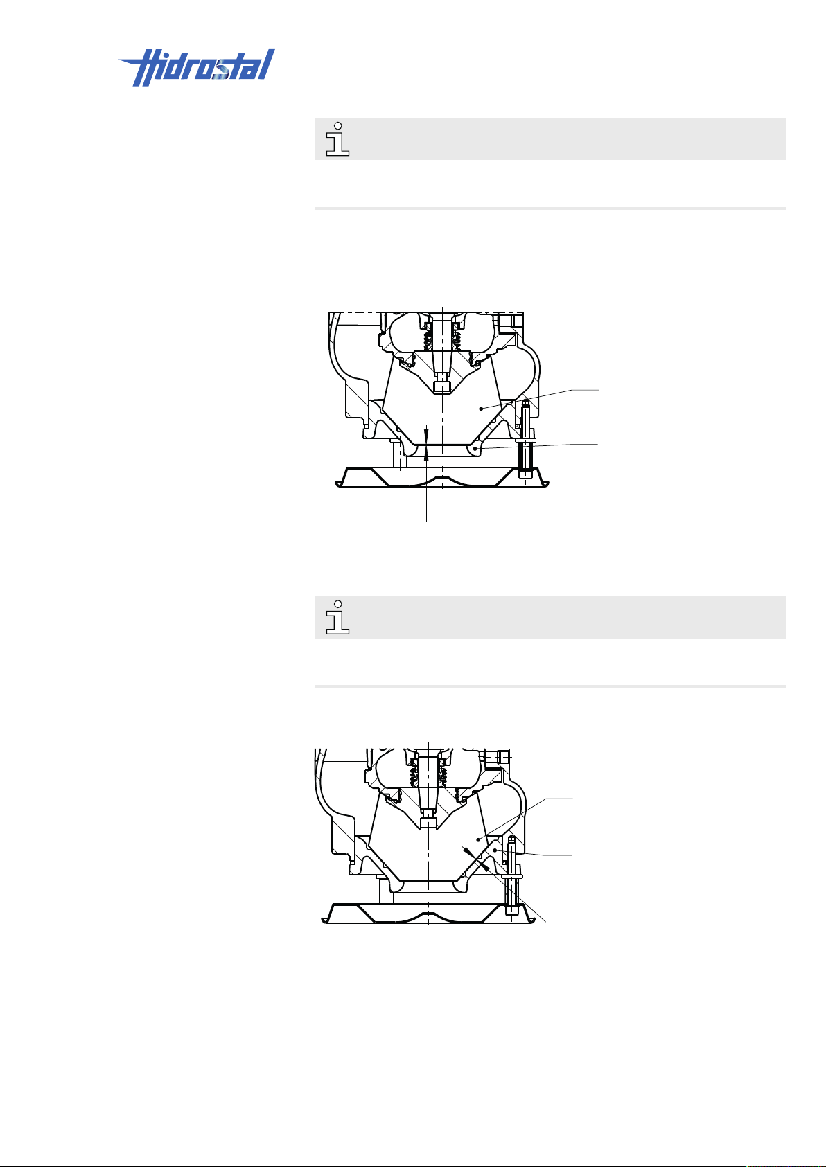
Impeller clearance “S” is the gap between impeller tip (1) and wear cone (2).
• Using a feeler gauge, check clearance “S” against the drawing. The
impeller tip must not be in contact with the wear cone.
NOTE
Contact the Service Centre if the impeller tip is in contact with the wear ring.
See Imprint [▶2].
8.4.3.3 Checking clearance “C”
Impeller clearance “C” is the gap between the impeller (1) and inlet cone (2).
1. Measure the gap between impeller (1) and inlet cone (2) with a feeler
gauge after 0, ¼, ½ and ¾ impeller rotations.
2. Compare the measured value with the max. permissible value listed in
the following table. The gap may be as small as can be but the impeller
(1) may not grind on the inlet cone (2) at any point.
Hidrostal AG 33 / 49
Page 34
8 | Maintenance
5
2
1
3
4
C
3. If the measured value exceeds the max. permissible value or the
impeller (1) grinds on the inlet cone (2), adjust the impeller clearance,
see Readjusting impeller clearance “C” [▶34].
Hydraulic size Max. impeller clearance “C”
A2Q, BN2, BE2, BN3,
BK3
0.3mm
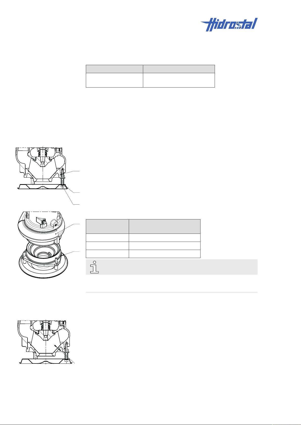
8.4.3.4 Readjusting impeller clearance “C”
The impeller clearance is adjusted with rings of different thickness.
1. Make sure that impeller clearance “S” is within the permissible range,
see Checking impeller clearance “S” [▶33].
2. Make sure that the pump is positioned in a vertical position on a surface
and attach lifting gear on the drive unit to prevent it from tipping.
3. Remove all hexagon socket cheese-head screws (1) and spring rings
(2).
4. Lift drive unit and pump hydraulic housing (3) off the suction cover (4).
Pump type Available spacer rings,
thickness in mm
A2Q 0.5 / 1.0 / 2.0
BN2, BE2 0.5 / 3.0 / 4.0 / 5.0
BN3, BK3 0.5 / 3.0 / 4.0 / 5.0
NOTE
With every 0.5mm spacer ring thickness, the impeller clearance “C” is
increased by approximately 0.35mm.
5. Insert rings (5) until the impeller clearance corresponds to the
specification. See table in chapter Checking clearance “C” [▶33].
6. Reassemble the pump.
7. Check clearance “C” between impeller and inlet cone with a feeler gauge
after 0, ¼, ½, and ¾ revolutions of the impeller. See Checking
clearance “C” [▶33].
8. Adjust the thickness of the spacer rings if clearance “C” does not meet
the specification.
34 / 49 Hidrostal AG
Page 35

8.4.4 Checking the oil
8.4.4.1 Purpose of checking the oil
The oil chamber acts as a barrier between the pump chamber on the one
side and the drive on the other. It prevents the medium leaking into the drive
unit.
The oil also dissipates heat from the drive unit to the medium and thus cools
the pump.
The oil chamber is sealed using a mechanical seal on the pump chamber
side and the drive side.
A mechanical seal is a "dynamic seal" which does NOT seal perfectly.
However, there is only little leakage through an intact seal.
Operational wear, in particular when conveying abrasive media, increases
the leakage of the mechanical seal to the pump chamber, and allows more
of the medium to enter the oil chamber.
Provided that the pump is fitted with a moisture sensor (option for BN3 and
BK3 only), and the sensor signals are properly evaluated by the control unit,
an alarm is triggered if an excessive amount of liquid leaks into the oil
chamber. The pump can then be shut down and repaired before costly
damage is caused to the drive unit.
If
• the pump is NOT fitted with a moisture sensor or
• the moisture sensor is NOT analysed by the system control
• a non-conductive medium is circulated or
• you are unsure whether the moisture sensor is working correctly or if its
measurements are evaluated correctly,
the oil must be checked regularly.
In this way, any damage of the mechanical seal on the pump chamber side
can be detected in time, and the pump can be shut down and repaired
before costly damage is caused to the drive unit.
If the mechanical seal functions properly, the oil is not subject to operational
wear, and can be used for an almost unlimited time.
Personnel:
• Trained personnel
Protective equipment:
• Safety goggles
• Protective clothing
• Safety shoes
Required tools:
• Clean collection tank
• Transparent beaker
• Funnel with a fine-particle sieve and/or filter paper
Prerequisites:
Maintenance | 8
Hidrostal AG 35 / 49
Page 36
8 | Maintenance
1
• Make sure that Preparation tasks for maintenance [▶31] has been
carried out first.
WARNING
Liquid possibly leaking under pressure.
Risk of severe injury!
• Wear safety goggles when opening the screw plug.
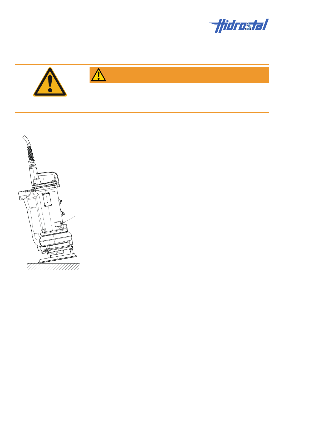
8.4.4.2 Drain in a vertical position
1. Stand pump on its suction flange.
2. Make sure that the pump is secured with lifting gear to prevent it from
tipping.
3. Tip the pump to slightly raise the position of the screw plug (1).
4. Loosen the screw plug until a brief hissing sound is heard or liquid runs
out.
ü If a brief hissing sound is heard:
5. Hold a cleaning cloth under the screw plug and tip the pump back into
the vertical position. If no more liquid leaks out, it can be expected that
little or no medium has leaked into the oil chamber.
Reinsert and tighten the screw plug (1).
ü If liquid is discharged:
6. A significant amount of liquid has leaked into the oil chamber. Tilt the
pump further to release any pressurised gas.
Once the pressure has been relieved: reinsert the screw plug (1).
7. Turn or tilt the pump so that the screw plug (1) is facing downwards.
8. Position a clean collection tank underneath the pump.
9. Remove the screw plug (1).
10. Allow the oil to drain into the collection tank.
8.4.4.3 Analysing the drained liquid
1. Pour the liquid from the collection tank into a clean, transparent
container, e.g. a beaker, and allow it to stand for several minutes.
ü If the liquid is bright, clear and thin, it could be the case that water has
leaked onto the base of the tank:
2. Continue to use the oil, see chapter Refilling the oil chamber [▶37].
3. Dispose of any water on the tank base as special waste.
ü If you are unsure about the oil condition:
4. Dispose of the liquid as special waste.
36 / 49 Hidrostal AG
Page 37
5. Refill the oil chamber with clean oil, see chapter Refilling the oil
1
3
2
45°
chamber [▶37].
ü If the liquid is dark in colour and/or cloudy and/or remains viscous, a high
level of medium has contaminated the oil:
6. Dispose of the liquid as special waste.
7. Send the pump to the service centre to repair the mechanical seal on the
pump chamber side.
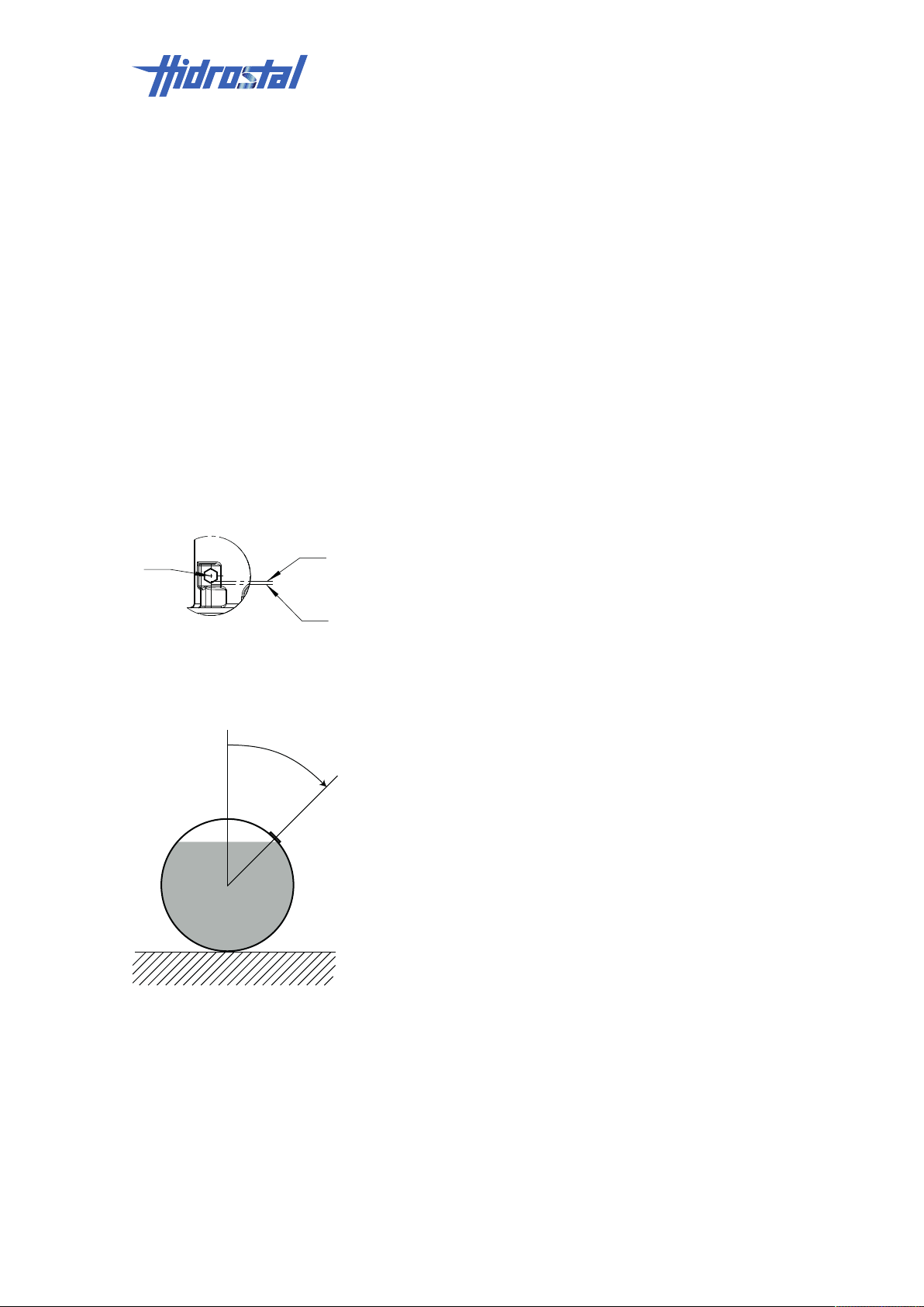
8.4.4.4 Refilling the oil chamber
1. Anneal the copper O-ring on the locking screw (1) or replace with a new
soft-annealed copper O-ring.
ü To fill the pump in a vertical position:
2. Stand the pump up.
ü To fill the pump in a vertical position, using the previously drained oil:
3. Pour the oil that has been separated from the water through a fineparticle sieve or filter paper into the chamber, top up with new oil, if
necessary, until the oil level is just below the filling opening (between (2)
and (3)).
Maintenance | 8
ü To fill the pump in a vertical position, using new oil:
4. Pour in new oil until the oil level is just below the filling opening (between
(2) and (3)).
ü To fill the pump in a horizontal position:
5. Turn the pump on its side so that the filling opening is turned approx. 45°
from its highest position.
ü To fill the pump in a horizontal position, using the previously drained oil:
6. Pour the oil that has been separated from the water through a fineparticle sieve or filter paper into the chamber, top up with new oil, if
necessary, until the oil level is just below the filling opening.
ü To fill the pump in a horizontal position, using new oil:
7. Pour in new oil until the oil level is just below the filling opening.
8. Reinsert the screw plug (1) and tighten by hand.
9. Re-start the pump.
8.4.5 Replacing the pump
Personnel:
• Qualified electricians
Protective equipment:
Hidrostal AG 37 / 49
Page 38
8 | Maintenance
• Protective clothing
• Hard hat
• Safety shoes
Prerequisites:
• Make sure that Preparation tasks for maintenance [▶31] has been
carried out first.
8.4.5.1 Checking the suitability of the replacement pump
• Make sure that the replacement pump is not damaged.
• Make sure that the information on the type plates of the defective pump
and the replacement pump are identical. If you are unsure, contact the
supplier.
• Make sure that the cable harness of the defective pump and the
replacement pump is identical (compare the wiring diagram of the
defective pump with that of the replacement pump).
8.4.5.2 Replacing the pump
1. Document the connections of the defective pump in the switch cabinet
using photos or written notes and compare the wiring diagram of the
defective pump with that of the replacement pump.
2. Make sure that the system or the affected system part is switched off
and cannot be switched back on unintentionally.
3. Make sure that all the lines to be disconnected, including the operational
safety component lines, have zero voltage.
4. Electrically isolate the connections of the defective pumps in the control
cabinet.
WARNING
Missing or insufficient earthing.
Risk of electric shock!
• Make sure that the pump is connected to the protective earth (PE).
5. Connect the replacement pump in accordance with the drawings or the
wiring diagram in the control cabinet.
8.4.5.3 Checking the rotational direction
WARNING
Turning impeller.
Risk of severe injury!
• Never touch the suction or pressure flange.
38 / 49 Hidrostal AG
Page 39
Maintenance | 8
NOTICE
Impeller loosens with wrong impeller rotation!
Risk of damage to property!
• Make sure that the rotational direction has been checked before
commissioning the replacement pump.
NOTE
Wrong rotational direction.
Drastically reduced flow rate!
• In case of incorrect rotational direction, simply swap over the pump's
cable conductors or speed which is in the wrong rotational direction at the
corresponding starting switch in the control panel.
• Never switch the primary feeders to the control panel. This would change
the rotational field for all consumer components.
NOTE
Do not suspend and switch on the pump! When switched on, the pump
would turn counter to the motor's direction of rotation and immediately turn
around its own axis!
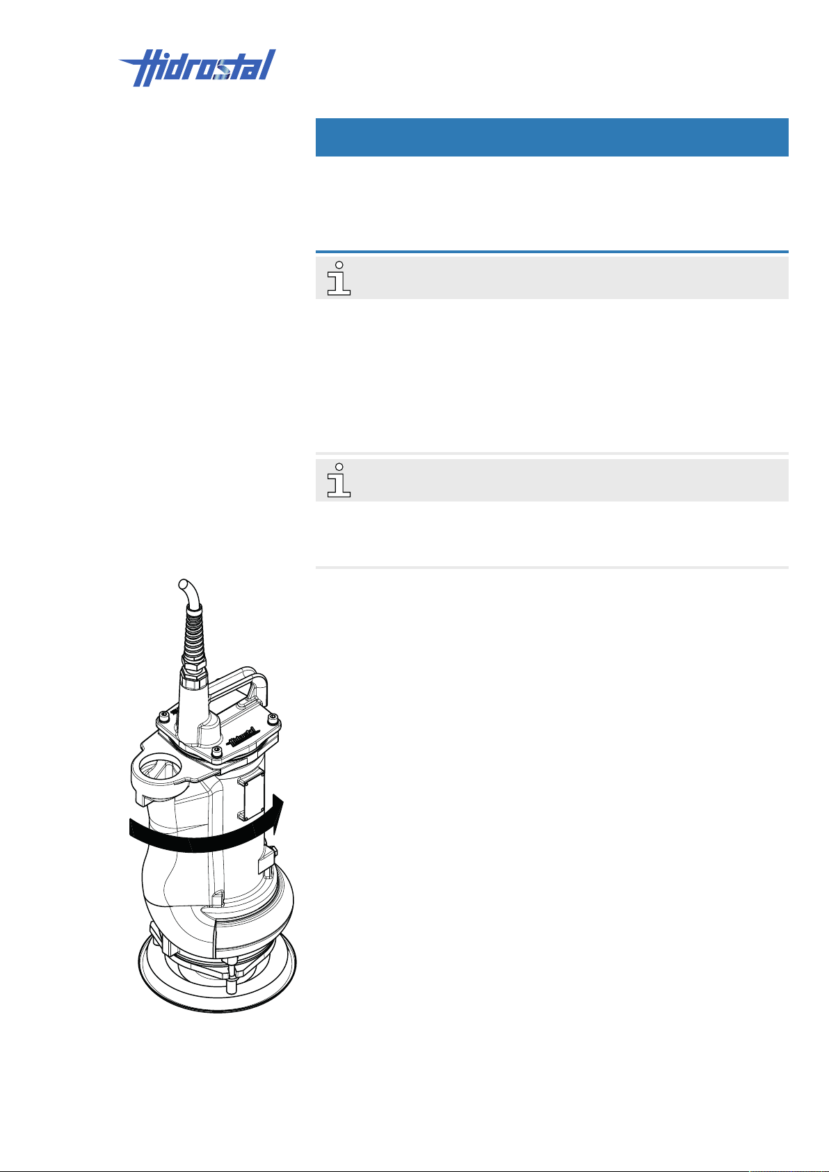
1. Make sure that the pump is positioned in a vertical position on a surface
and attach lifting gear on the drive unit to prevent it from tipping.
2. Run the pump for approx. one second and observe the direction of the
starting jolt.
ü When viewed from above, if the pump jolts in an anti-clockwise direction
(see adjacent figure):
3. The direction of rotation is correct, proceed with Pt.5.
ü When viewed from above, if the pump jolts in a clockwise direction:
4. The direction of rotation is incorrect.
With direct start-up: switch 2 of the 3 cable conductors for the tested
rotation speed on the control panel.
With a star/triangle start-up configuration: exchange U1 with W1 and U2
with W2 in the control panel.
5. On pump units with several speeds, repeat the test for each speed.
6. Commission the pump.
Hidrostal AG 39 / 49
Page 40

8 | Maintenance
8.5 Measures after completion of work
The following steps are to be executed following completion of maintenance
work and prior to switch-on of the system:
1. Check all screw connections that were previously loosened for tightness.
2. Check if all protective devices and covers that were previously removed
are properly installed again.
3. Ensure that all tools, materials and other equipment used have been
removed from work area.
4. Clean work area and device and remove any escaped substances, such
as liquids, processing material or the like.
5. Ensure that all safety devices of the system function properly.
6. Ensure that no persons are in the danger zone.
40 / 49 Hidrostal AG
Page 41
9 Faults
The following chapter describes possible causes for malfunctions and what
needs to be done to correct them. If malfunctions occur more frequently,
shorten maintenance intervals according to actual load. If malfunctions
cannot be corrected by the following information, contact the manufacturer
or service partner, see Imprint [▶2].
9.1 Safety
Electrical system
DANGER
Contact with live parts.
Risk of fatal injury!
• Before starting work, switch off the electrical supply and secure against
switching back on.
Faults | 9
Secure against switching on
WARNING
Unauthorised switching on of the energy supply.
Risk of severe injury!
• Make sure that the energy supply cannot be switched on if there are
persons in the danger zone.
In the event of faults The following fundamentally applies:
1. Push the emergency STOP immediately for faults that represent an
immediate danger to persons or property.
2. Turn off system and protect against restart or an automatic switch-on!
3. Immediately inform the supervisors at the working site about the fault.
4. Determine the cause of the fault.
5. Depending on the type of malfunction, either have the malfunction
rectified by authorised qualified personnel or rectify it yourself.
NOTE
The malfunction table below provides you with information regarding who is
authorised to troubleshoot the malfunction.
Hidrostal AG 41 / 49
Page 42
9 | Faults
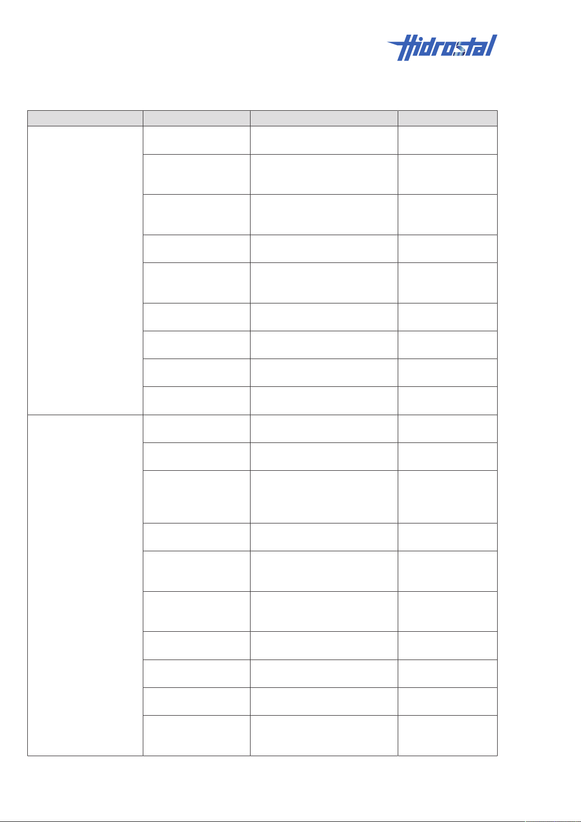
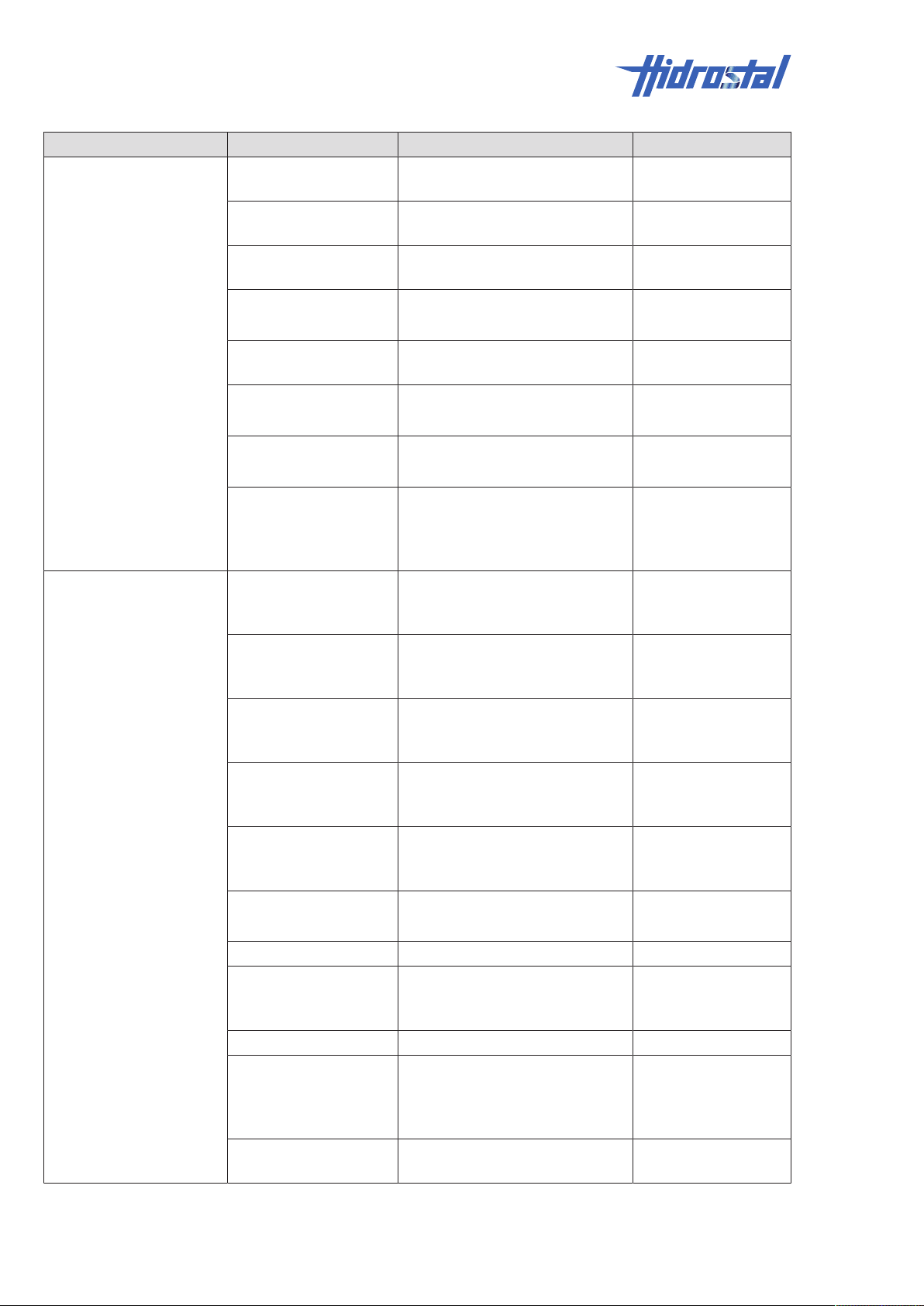
9.2 Fault table
Error description Cause Remedial action Personnel
No delivery Pump not vented Vent pump Instructed persons
(operators)
Speed too low Check all three phases for
Speed too low in
frequency inverter (FI)
operation
Air penetrates at
suction side
Pressure line
obstructed/ gate valve
closed
Air or gas in conveyed
medium
Air or gas at the rear
side of the impeller
Delivery height too high
(exceeds calculation)
Impeller or suction line
obstructed
Insufficient flow rate Air penetrates at
suction side
Air or gas in conveyed
medium
Wrong rotational
direction
Increased vibrations
Delivery height too high
(exceeds calculation)
Speed too low Check all three phases for
Thick matter
concentration higher
than assumed
Impeller or suction line
obstructed
Excessive impeller
clearance
Impeller damaged Check the impeller for damage,
Voltage too low Check the voltage. With star-
failure, check mains frequency,
check phase connections
Check the speed selected at theFIInstructed persons
Check suction line and/or fluid
level
Check pressure line/gate valve Instructed persons
Check the conveyed medium for
air or gas
Check the conveyed medium for
air or gas
Check delivery height, check
gate valve
Check pump and suction line for
obstructions
Check suction line and/or fluid
level
Check the conveyed medium for
air or gas
Check the rotational direction,
correct if necessary. See chapter
Checking the rotational
direction [▶38]
Check the delivery height Instructed persons
failure, check mains frequency,
check phase connections
Check thick matter concentration Instructed persons
Check pump and suction line for
obstructions
Check the impeller clearance Instructed persons
replace it if necessary
delta starting: Check the
switchover function
Qualified electricians
(operators)
Instructed persons
(operators)
(operators)
Instructed persons
(operators)
Instructed persons
(operators)
Instructed persons
(operators)
Instructed persons
(operators)
Trained personnel
Instructed persons
(operators)
Qualified electricians
(operators)
Qualified electricians
(operators)
Instructed persons
(operators)
(operators)
Service centre
Qualified electricians
42 / 49 Hidrostal AG
Page 43
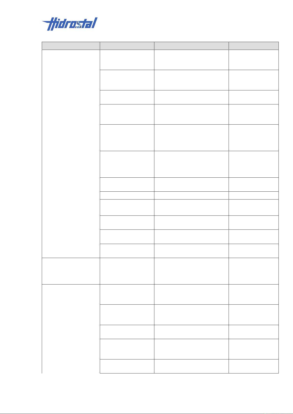
Error description Cause Remedial action Personnel
Insufficient delivery
pressure
Speed too low Check all three phases for
failure, check mains frequency,
Qualified electricians
check phase connections
Speed too low in
frequency inverter (FI)
Check the speed selected at theFIInstructed persons
(operators)
operation
Air or gas in conveyed
medium
Thick matter
concentration higher
Check the conveyed medium for
air or gas
Instructed persons
(operators)
Check thick matter concentration Instructed persons
(operators)
than assumed
Wrong rotational
direction
Check the rotational direction,
correct if necessary. See chapter
Qualified electricians
Checking the rotational
direction [▶38]
Excessive impeller
clearance
Check the impeller clearance,
readjust it if necessary. See
Trained personnel
chapter Check/readjust
impeller clearance [▶32]
Impeller damaged Check the impeller for damage,
Service centre
replace it if necessary
Voltage too low Check voltage Qualified electricians
Impeller too small Check impeller, replace if
necessary
Air or gas at the rear
side of the impeller
Check the conveyed medium for
air or gas
Trained personnel
Service centre
Instructed persons
(operators)
Air entering suction line Check level monitoring Instructed persons
(operators)
Decrease in flow rate,
or
Air or gas in conveyed
medium
Air penetrates at
suction side
Check the conveyed medium for
air or gas
Instructed persons
(operators)
Check level monitoring Instructed persons
(operators)
loss of pressure after
startup
Vibrations Speed too high Check all three phases for
Qualified electricians
failure, check mains frequency,
check phase connections
Speed too high in
frequency inverter (FI)
Check the speed selected at the
FI; reduce it if necessary
Instructed persons
(operators)
operation
Air entering suction line Check level monitoring Instructed persons
(operators)
Pressure line
obstructed/ gate valve
Check pressure line/gate valve Instructed persons
(operators)
closed
Air or gas in conveyed
medium
Check the conveyed medium for
air or gas
Instructed persons
(operators)
Faults | 9
Hidrostal AG 43 / 49
Page 44
9 | Faults
Error description Cause Remedial action Personnel
Delivery height too high
(exceeds calculation)
Impeller or suction line
obstructed
Impeller damaged Check the impeller for damage,
Check delivery height, check
gate valve
Check pump and suction line for
obstructions
Instructed persons
(operators)
Instructed persons
(operators)
Service centre
replace it if necessary
Motor damaged Check the motor, repair it if
necessary
Loose anchoring Check the anchoring; correct if
Qualified electricians
Service centre
Trained personnel
necessary
Bearings worn out Check the bearing for damage,
replace it if necessary
Impeller out-of-balance Check impeller, replace if
necessary
Impeller brushes
against suction cover
Check the impeller clearance,
readjust it if necessary. See
Trained personnel
Service centre
Trained personnel
Service centre
Trained personnel
chapter Check/readjust
impeller clearance [▶32]
Motor overloaded Pressure line
obstructed/ gate valve
Check pressure line/gate valve Instructed persons
(operators)
closed
Thick matter
concentration higher
Check thick matter concentration Instructed persons
(operators)
than assumed
Speed too high Check all three phases for
Qualified electricians
failure, check mains frequency,
check phase connections
Speed too high in
frequency inverter (FI)
Check the speed selected at the
FI; reduce it if necessary
Instructed persons
(operators)
operation
Specific gravity of
delivery medium higher
Check the specific weight of the
conveyed medium
Trained personnel
than assumed
Motor damaged Check the motor, repair it if
necessary
Qualified electricians
Service centre
Voltage too low Check voltage Qualified electricians
Loss of coolant Check coolant / oil level, top up if
Trained personnel
necessary. See chapter
Checking the oil [▶35]
Wrong impeller installed Check the impeller type Service centre
Impeller brushes
against suction cover
Check the impeller clearance,
readjust it if necessary. See
Instructed persons
(operators)
chapter Check/readjust
impeller clearance [▶32]
Thick sludge and small
impeller clearance
Increase the impeller clearance Instructed persons
(operators)
44 / 49 Hidrostal AG
Page 45
Faults | 9
Error description Cause Remedial action Personnel
Pump is not running Main switch is OFF Set main switch to “ON” position Instructed persons
(operators)
Thermal overcurrent trip
responded or is not
properly connected
Motor damaged Check the motor, repair it if
Voltage too low Check voltage Qualified electricians
ON level not reached;
defective sensor or
switch
Pump is very noisy Speed too high in
frequency inverter (FI)
operation
Air penetrates at
suction side
Air or gas in conveyed
medium
Suction head too high Check suction head Instructed persons
Insufficient suction
pressure with hot
liquids
Suction pipe
insufficiently
submerged
Motor damaged Check the motor, repair it if
Loose anchoring Check the anchoring; correct if
Impeller brushes
against suction cover
Pump runs to the right
of the pump
characteristic curve
Check overcurrent trip Qualified electricians
Qualified electricians
necessary
Check fluid level; check function
of level switch, replace it if
necessary
Check the speed selected at the
FI; reduce it if necessary
Check suction line and/or fluid
level
Check the conveyed medium for
air or gas
Check suction pressure, increase
if necessary
Check immersion depth of
suction pipe
necessary
necessary
Check the impeller clearance,
readjust it if necessary. See
chapter Check/readjust
impeller clearance [▶32]
Check operating data and
operating conditions
Service centre
Trained personnel
Instructed persons
(operators)
Instructed persons
(operators)
Instructed persons
(operators)
(operators)
Trained personnel
Instructed persons
(operators)
Qualified electricians
Service centre
Trained personnel
Trained personnel
Trained personnel
9.3 Measures after completion of work
The following steps are to be executed following completion of maintenance
work and prior to switch-on of the system:
1. Check all screw connections that were previously loosened for tightness.
2. Check if all protective devices and covers that were previously removed
are properly installed again.
3. Ensure that all tools, materials and other equipment used have been
removed from work area.
Hidrostal AG 45 / 49
Page 46

9 | Faults
4. Clean work area and device and remove any escaped substances, such
as liquids, processing material or the like.
5. Ensure that all safety devices of the system function properly.
6. Ensure that no persons are in the danger zone.
46 / 49 Hidrostal AG
Page 47
10 Disassembly
Once the system has reached the end of its service life, disassemble it and
dispose of it in an environmentally compatible way.
10.1 Safety
Electrical system
DANGER
Contact with live parts.
Risk of fatal injury!
• Before starting work, switch off the electrical supply and secure against
switching back on.
Disassembly | 10
Incorrect disassembly
WARNING
Stored residual energy, sharp edged components, points and corners on
and in the system or on the required tools.
Risk of severe injury!
• Before starting work, make sure that there is sufficient space.
• Be careful with open, sharp-edged components.
• Make sure that the work area is orderly and clean! Loose components
and tools stacked or lying around are potential sources of accident.
• Correctly dismantle components. Caution: some components are heavy.
Where necessary, use hoisting devices.
• Secure components so that they cannot fall or tip.
• If in doubt, consult the manufacturer.
10.2 Disassembly
Prior to the start of disassembly:
• Turn off system and protect against restart.
• Physically disconnect the system from all power supplies and allow stored
residual energy to discharge.
• Remove operating and supplementary materials and any remaining
processing materials and dispose of appropriately.
Then, clean assemblies and parts correctly and dismantle modules based on
the local workplace safety and environmental regulations.
Hidrostal AG 47 / 49
Page 48

10 | Disassembly
10.3 Disposal
If no return or disposal agreements have been made, then dismantled
components must be recycled as follows:
• Scrap the metal parts.
• Plastic elements must be recycled.
• Other components must be sorted and disposed of according to the type
of material.
NOTE
Incorrect disposal of materials.
Risk of environmental pollution!
• Electrical scrap, electronic components, lubricants and other auxiliary
materials must only be disposed of by approved, specialist companies.
• If in doubt, contact the local authorities or specialist waste disposal
companies to inquire about environmental disposal.
48 / 49 Hidrostal AG
Page 49

11 Appendix
• Technical drawings
• CE Declaration of Conformity
• Spare parts list
• Wiring diagram
Appendix | 11
Hidrostal AG 49 / 49
 Loading...