

Page 1
9292 Jeronimo Road
Irvine, CA 92618-1905
Quick Installation Guide
V100 DOOR/READER INTERFACE
PROPRIETARY INFORMATION. This document contains proprietary information which may not be duplicated,
published or disclosed to others, or used for any purpose without written permission from HID Corporation. 2004
© HID Corporation. All rights reserved.
Document Version 1.1
August 4, 2005
Document Number 6080-907B
Page 2

VertX V100 (CS) Quick Installation Guide
Contents
QUICK START, VERTX (CS) V100 Door/Reader Interface Panel.............................................1
Introduction.................................................................................................................................3
Parts List (included) ..........................................................................................................3
Product Specifications....................................................................................................... 3
Cable Specifications.......................................................................................................... 3
Overview......................................................................................................................................4
Step 1 Preparations ....................................................................................................................4
1.1 What you need before getting started ...................................................................4
1.2 V100 ...................................................................................................................... 4
Step 2 Hardware Installation......................................................................................................5
2.1 Mounting Instructions ............................................................................................5
2.2 Wiring VertX ..........................................................................................................5
Contact Information....................................................................................................................8
August 2005 Page 2 of 9
2005 © HID Corporation. All rights reserved.
Page 3
VertX V100 (CS) Quick Installation Guide
Introduction
VertX™ CS is the first family of access controllers designed specifically for alarm dealers for direct
connection to central stations. Because it was designed with central station in mind, VertX CS works with
software from leading central station automation providers, including Bold Technologies, DICE and
GE MAS.
The V100 is designed to be controlled by a VertX V1000 Access Controller that will also manage
communications with the central station automated software. The V100 Door/Reader Interface panel
controls two sets of door devices or one door with Card In/Card Out (a reader on both sides of the same
door.)
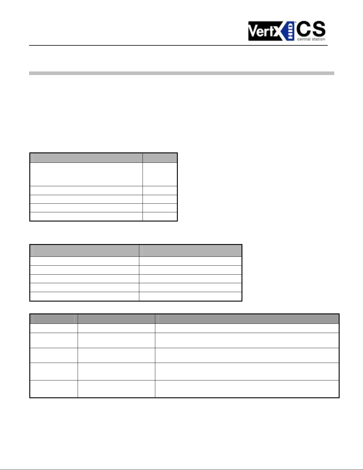
Parts List (included)
Parts List (included) Quantity
VertX™ V100 Door/Reader Interface
Note: The V100 panel has a plastic base
and is covered with a Plastic or Mylar cover.
Mounting screws 4
2.2K EOL resistors 4
Quick Installation Guide 1
Installation Wiring Diagram Example 1
1
Note: A VertX V1000 Access Controller is required.
Product Specifications
Description Specification
Power Supply 12-16VDC
Maximum current at 12VDC per V100 1 Amp
Average operating current at 12VDC
Operating temperature range 32°-122°F (0°-50°C)
Humidity 5% to 95% non-condensing
450mA (with two R40 iCLASS Readers)
Cable Specifications
Cable Type Length Specification
RS-485 *
Input Circuits * 500 feet (150 m)
Output Circuits * 500 feet (150 m)
Wiegand
Power Supply
+12 VDC IN
* Minimum wire gauge depends on cable length and current requirements.
4000 feet (1220 m) to V1000
500 feet (150 m) to reader ALPHA 1299C, 22AWG, 9-conductor, stranded, overall shield.
---- Refer to your Power Supply Installation Guide.
Belden 3105A, 22AWG twisted pair, shielded 100Ω cable, or equivalent.
2-conductor, shielded, using ALPHA 1292C (22AWG) or Alpha 2421C
(18AWG), or equivalent.
2-conductor, using ALPHA 1172C (22AWG) or Alpha 1897C (18AWG), or
equivalent.
Fewer conductors needed if all control lines are not used.
August 2005 Page 3 of 9
2005 © HID Corporation. All rights reserved.
Page 4

VertX V100 (CS) Quick Installation Guide
Overview
The following outlines what is required to install the V100 Door/Reader Interface panel.
Step 1 Preparations
1.1 What you need before getting started
Prior to starting the installation, please completely read through this guide.
CAUTION: The V100 is sensitive to Electrostatic Discharges (ESD). Observe precautions while
handling the circuit board assembly by using proper grounding straps and handling precautions at
all times.
1.2 V100
1. If the V100 will be attached to the end of the RS-485 bus, install a
terminating jumper on the termination resistor pins P8 on the cover
(P10 on the PCB) of the V100.
2. If the V100 is being installed as part of an array, or in a third party
enclosure, follow the directions provided by the Integrator or Dealer.
Terminating
Jumper
August 2005 Page 4 of 9
2005 © HID Corporation. All rights reserved.
Page 5

VertX V100 (CS) Quick Installation Guide
Step 2 Hardware Installation
2.1 Mounting Instructions
1. The V100 should always be mounted in a secure area.
2. Mount the V100 using the four mounting screws (provided) or other appropriate fasteners. Place the
fasteners in the corner holes of the base.
3. The V100 panel can be stacked with or without the cover. Do not remove the plastic base. Make sure
to position the V100 panel in such a way as to provide room for wiring, air-flow and cable runs.
2.2 Wiring VertX
CAUTION: Connectors on the V100 sides are positioned to be mirror images and are not
interchangeable once the installation is complete. Therefore, you cannot unplug the connector from
one side of the board and plug it into the corresponding connector on the other side.
1. Power and Alarm input connections: Connect power by providing 12VDC to the P7 connector.
+12VDC goes to Pin 1 and Ground on Pin 2. The Bat Fail, AC Fail, and Tamper switch inputs are
wired as shown in the table. Connect the Bat Fail and AC Fail inputs to battery low/failure and AC
failure contacts provided on the power supply. Connect the Tamper input to a tamper switch on the
enclosure.
Pin # P7
1 +12VDC
2 Ground
2. Reader Connections: Connect Wiegand or
clock-and-data interfaces to the V100 using
the connection table shown. You can
connect up to 10 signal lines for the reader.
Use as many of the signal lines as required
for your reader interface.
Note: Connect the data return line to the
same ground as the reader power if the
reader is not powered by the VertX units
12VDC.
Pin # V100 P1 V100 P4
1 Reader Power Shield Ground
2 Ground Hold
3 Data 0 / Data Beeper
4 Data 1 / Clock Red LED
5 Data Return Green LED
6 Green LED Data Return
7 Red LED Data 1 / Clock
8 Beeper Data 0 / Data
9 Hold Ground
10 Shield Ground Reader Power
3 Bat Fail 4 Bat Fail +
5 AC Fail 6 AC Fail +
7 Tamper 8 Tamper +
August 2005 Page 5 of 9
2005 © HID Corporation. All rights reserved.
Page 6

VertX V100 (CS) Quick Installation Guide
3. RS-485 Connections: Connect the V100 to the V1000 through the RS-485 cable. See the V1000
Quick Install Guide for further information.
CAUTION: The V1000 RS-485 Ports 1 & 2 (P1) are a common bus and therefore cannot have
duplicate Interface Addresses assigned. The same is true of the V1000 RS-485, Ports 3 & 4 (P4).
For example, Interface Address 0 (factory default) cannot be assigned to both Ports 1 & 2 (P1).
4. Interface Address – Set the interface address by turning the Address dial. Ensure that
the V100 Interface Address is documented in the Hardware Installation Worksheet (found
in the back of the HID VertX V1000 Quick Install guide).
5. Output Connections – All Output connections are used for general
purpose controls. The following table shows where the various outputs are
located. Pin numbers shown use the convention “NO/C/NC”.
For example, Output 1, V2000: P3 Pin1 is NO (Normally open) and Pin 2 is
C (Common) and Pin 3 is NC (Normally closed).
Note: Relay contacts are rated for 2Amps @ 30VDC.
Output
number
1
2
3
4
V2000 V1000 V100 V200 V300
P3 Pins 1/2/3
Strike (lock)
Relay 1
P3 Pins 4/5/6
Aux Relay 1
P6 Pins 6/5/4
Strike (lock)
Relay 2
P6 Pins 3/2/1
Aux Relay 2
P14 Pins
2/3/4
P11 Pins
6/5/4
P3 Pins 1/2/3
Strike (lock)
Relay 1
P3 Pins 4/5/6
Aux Relay 1
P6 Pins 6/5/4
Strike (lock)
Relay 2
P6 Pins 3/2/1
Aux Relay 2
P3 Pins 2/3/4 P1 Pins 1/2/3
P6 Pins 3/2/1 P1 Pins 4/5/6
P1 Pins 7/8/9
P2 Pins 1/2/3
August 2005 Page 6 of 9
2005 © HID Corporation. All rights reserved.
Page 7

VertX V100 (CS) Quick Installation Guide
Output
number
5 P2 Pins 4/5/6
6 P2 Pins 7/8/9
7 P4 Pins 9/8/7
8 P4 Pins 6/5/4
9 P4 Pins 3/2/1
10 P5 Pins 9/8/7
11 P5 Pins 6/5/4
12 P5 Pins 3/2/1
V2000 V1000 V100 V200 V300
6. Input Connections – Input connections are used for a combination of specific functions such as
Request-to-Exit (REX), Door monitor, etc. They can also be used for general purpose monitoring.
Connect one side of the switch or contact to the + (plus) lead and the other to the – (minus) lead. The
following table shows where the inputs are located. Pin numbers shown on the cover use the
convention +/–.
The default REX switch configuration is normally open (NO) unsupervised (no EOL resistors), while the
default door switch (DS) configuration is Normally Closed (NC) unsupervised (no EOL resistors). All
other input points are defaulted for NO switches and are unsupervised (no EOL resistors).
Any input can be configured as a supervised input. They can be configured for resistor values of 1K –
6K Ohm. The setup of supervised inputs should be done during configuration of the VertX units via the
central station automation software (host) or using the Calibrate Input tool explained in the HID VertX
V1000 Quick Installation guide.
Example: Input 1, V1000 is: P14 Pin1 is + and Pin 2 is -.
The default input will be all:
Supervised inputs can be configured for:
Input
Number
1
2
3
4
August 2005 Page 7 of 9
V2000 V1000 V100 V200 V300
P2 Pins 1/2
Door Monitor
P2 Pins 3/4
REX Input
P5 Pins 4/3
Door Monitor
P5 Pins 2/1
REX Input
P14 Pins 1/2
P11 Pins 4/3
P7 Pins 8/7
Tamper
P7 Pins 6/5
AC Fail
2005 © HID Corporation. All rights reserved.
P2 Pins 1/2
Door Monitor
P2 Pins 3/4
REX Input
P5 Pins 4/3
Door Monitor
P5 Pins 2/1
REX Input
P1 Pins 1/2 P6 Pins 2/1
P1 Pins 3/4 P3 Pins 1/2
P1 Pins 5/6
P1 Pins 7/8
P7 Pins 8/7
Tamper
P7 Pins 6/5
AC Fail
Page 8

VertX V100 (CS) Quick Installation Guide
Input
Number
5
6
7
8 P2 Pins 5/6
9 P4 Pins 10/9
10 P4 Pins 8/7
11 P4 Pins 6/5
12 P4 Pins 4/3
13 P4 Pins 2/1
14 P5 Pins 6/5
15 P5 Pins 4/3
16 P5 Pins 2/1
17
18
19
V2000 V1000 V100 V200 V300
P7 Pins 8/7
Tamper
P7 Pins 6/5
AC Fail
P7 Pins 4/3
Batt Fail
P7 Pins 4/3
Batt Fail
P7 Pins 8/7
Tamper
P7 Pins 6/5
AC Fail
P7 Pins 4/3
Batt Fail
P1 Pins 9/10 P7 Pins 4/3
Batt Fail
P2 Pins 1/2
P2 Pins 3/4
P7 Pins 8/7
Tamper
P7 Pins 6/5
AC Fail
P7 Pins 4/3
Batt Fail
Contact Information
HID Corporation
Web Site http://www.hidcorp.com
Main Phone (949) 598-1600
Sales (800) 210-4744
Technical Support (800) 237-7769
August 2005 Page 8 of 9
2005 © HID Corporation. All rights reserved.
929274 Jeronimo Road, Irvine, CA 92618-1905
Fax (949) 598-1698
Page 9

p
VertX V100 (CS) Quick Installation Guide
All National and local Electrical codes apply.
• This equipment is intended to be powered from a limited power source output of a
previously certified power supply.
• Changes or modifications not expressly approved by the party responsible for
compliance could void the user’s authority to operate the equipment.
Class A Digital Devices
FCC Compliance Statement: This equipment has been tested and found to comply with the limits for a
Class. A digital device, pursuant to part 15 of the FCC Rules. These limits are designed to provide
reasonable protection against harmful interference when the equipment is operated in a commercial
environment. This equipment generates, uses, and can radiate radio frequency energy and, if not installed
and used in accordance with the instruction manual, may cause harmful interference to radio
communications. Operation of this equipment in a residential area is likely to cause harmful interference in
which case the user will be required to correct the interference at his own expense.
Class B Digital Devices
FCC Compliance Statement: This equipment has been tested and found to comply with the limits for a
Class B digital device, pursuant to the limits for a Class B digital device, pursuant to part 15 of the FCC
Rules. These limits are designed to provide reasonable protection against harmful interference in a
residential installation. This equipment generates, uses, and can radiate radio frequency energy and, if not
installed and used in accordance with the instructions, may cause harmful interference to radio
communications. However, there is no guarantee that interference will not occur in a particular installation.
If this equipment does cause harmful interference to radio or television reception, which can be determined
by turning the equipment off and on, the user is encouraged to try to correct the interference by one or
more of the following measures:
• Reorient or relocate the receiving antenna.
• Increase the separation between the equipment and the receiver.
• Connect the equipment into an outlet on a circuit different from that to which the receiver is
connected.
• Consult the dealer or an ex
erienced radio/TV technician for help.
August 2005 Page 9 of 9
2005 © HID Corporation. All rights reserved.
 Loading...