

Page 1
EDGE EVO
15370 Barranca Parkway
Irvine, CA 92618-2215
USA
© 2009 - 2011 HID Global Corporation. All rights reserved.
The EDGE EVO Door module is wired to interface with the EDGE EVO device (Hi-O Networked Controler & Reader or Networked
Controller) with electronic door components. Designed for providing interface to traditional discrete access inputs and outputs, the Door
Module provides four input analog/digital inputs and two outputs. Congure the Door Module in two ways; as a primary door interface to
REX, Door Position Switch, Battery Fail, Power Fail, Lock, and Aux (Group 1) or as a general purpose input/output module (Group 2).
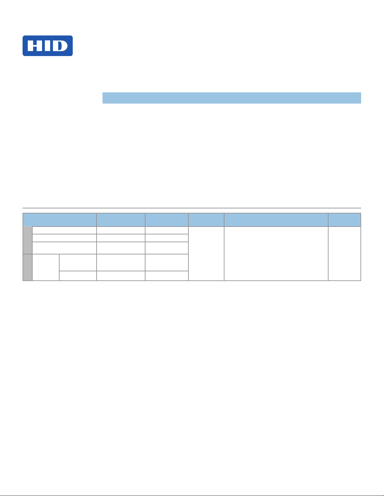
Specications
Door Module
EDM-M
InstallatIon GuIde
82342-901, Rev B.1
October 2011
®
CONDITIONS VOLTAGE DC (VDC) CURRENT (Amp)
DC Input (NSC) 10.8 to 24VDC 0.04Amp
DC Input (MAX) 10.8 to 24VDC 0.80Amp
Input
Supervised inputs
(AC, Batt, REX, Door Mon) (MAX)
Regulated or
Strike / AUX
NC or NO
DC Output
Output
Unregulated (Wet)
Jumpers
Dry Jumpers +12 to +24VDC External 2.00 ** Amp
* Shared between relays
** Each relay
0-5V Reference 0.005 (Sink)
10-24VDC 0.31 to 0.70Amp *
OPERATING
TEMPERTURE
32° - 122°F
(0° - 50° C)
CABLE LENGTH
Inputs = 500 ft (150 m)
Outputs = 500 ft (150 m)
Hi-O CAN Bus Total Length 100 ft (30 m) -
22 AWG ● 0.65mm ● 0.33mm
Maximum between drops 30 ft (10 m)
22 AWG ● 0.65mm ● 0.33mm2
2
UL REF
NUMBER
MEDMAxNN
x = K for Black
G for Grey
Page 2
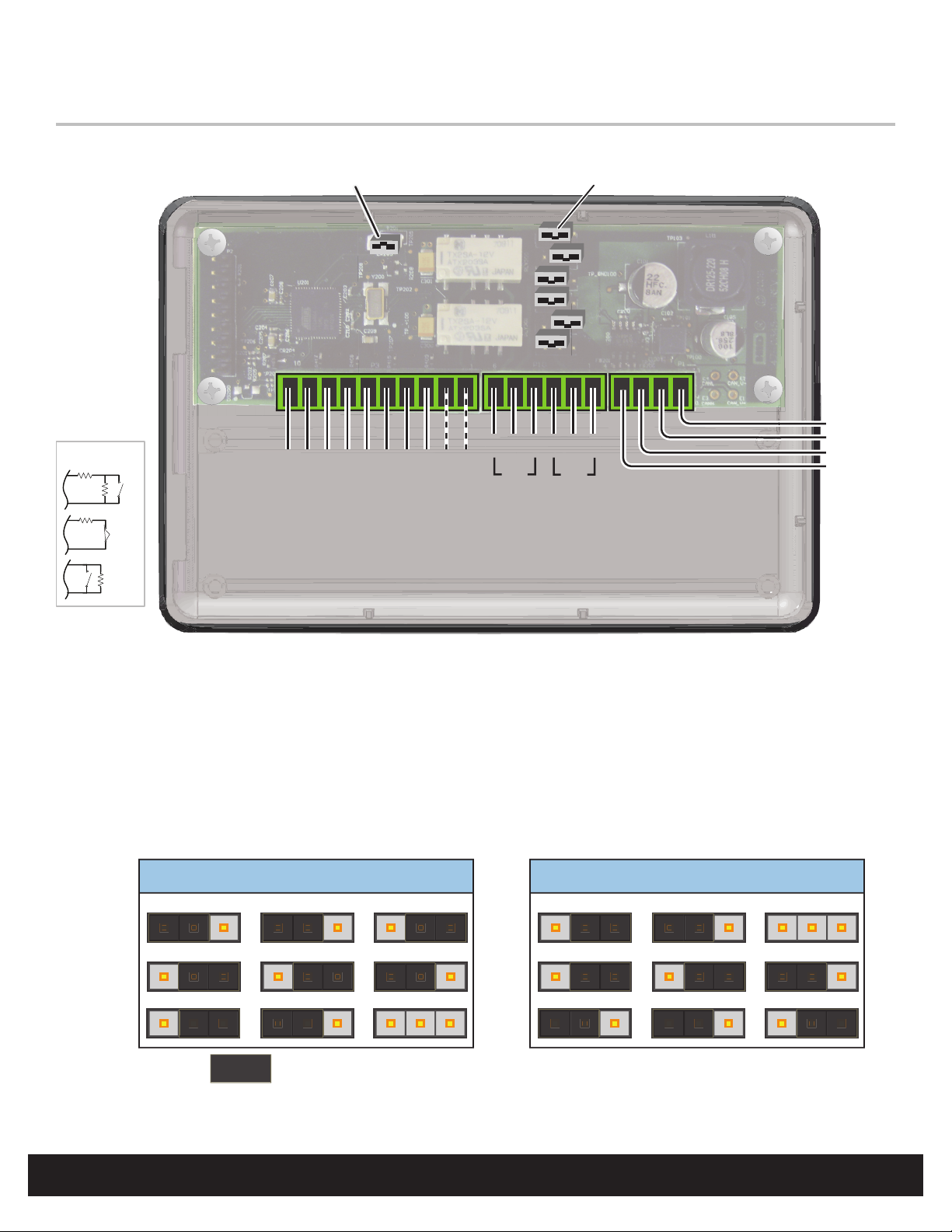
Door Module
Hi-O Group Select Jumper
EDM-M
Wiring
Short = Group 1, Open = Group 2
( )
Outside Door Inside Door
Optional
Supervised Inputs
1-6K
1-6K
1-6K
N/O
N/C
Relay Jumpers
P9
P5
P8
P6
P4
P7
10 P3 14 P1 1
-+
-+-+-+
REX
BATT AC
SENSE
Door
Mon
6 P10 1
NO
*
COM
AUX
NC
NO
DS
NC
COM
* Internal Optical Tamper Disable Jumper
82342-901 B.1
CAN V+
GND
CAN H
CAN L
HI-O CANbus
1-6K
N/O
Note: Connect the Door Monitor to avoid a Force Door Alarm.
Internal Optical Tamper
To disable the internal optical tamper sensor for the right side PCB (reader interface board), attach a jumper wire from P3 pin 1
to P3 pin 2.
Note: If desiring an external tamper, wire an unsupervised Normally Closed contact and replace the jumper.
Relay Jumpers
AUX Wet
CAN V+
3 1
AUX Wet
+12VDC
3 13 1 3 1
AUX Dry
P9
P5
P8
DS Wet
CAN V+
DS Wet
+12VDC
3 13 1
DS Dry
P6
P4
P7
INSTALLATION GUIDE
2
JUMPER =
©2009 - 2011 HID Global Corporation. All rights reserved.
Page 3

82342-901 B.1
Door Interface Board Groups 1 and 2
Group 1
Following are the inputs when the unit is congured for Group 1.
Input Port Pin
AC - P3 Pin3
AC + P3 Pin 4
BATT - P3 Pin 5
BATT + P3 Pin 6
REX - P3 Pin 7
REX + P3 Pin 8
Door Mon - P3 Pin 9
Door Mon + P3 Pin 10
Group 2
Following are the inputs when the unit is congured for Group 2.
Input Port Pin
Input 4 - P3 Pin3
Input 4 + P3 Pin 4
Input 3 - P3 Pin 5
Input 3 + P3 Pin 6
Input 2 - P3 Pin 7
Input 2 + P3 Pin 8
Input 1 - P3 Pin 9
Input 1 + P3 Pin 10
Door Module
EDM-M
©2009 - 2011 HID Global Corporation. All rights reserved.
INSTALLATION GUIDE
3
Page 4

Regulatory
UL
Connect only to a Listed Access Control / Burglary power-limited power supply, or Listed Access Control / Burglary PoE (Power-over-Ethernet) adapter.
All National and local Electrical codes apply. Install in accordance with NFPA70 (NEC), Local Codes, and authorities having jurisdiction.
Indoor use only.
EDGE EVO Modules are UL Listed for installation within a protected area.
Mount onto UL Listed Single-Gang electrical box.
All panic and alarm hardware and equipment shall be UL Listed.
All cabling and wire shall be UL Listed or Recognized and suitable for the application.
All splices and connections shall be mechanically secure and bonded electrically.
For operation, testing and maintenance, refer to the EDGE EVO Hi-O Networked Controller & Reader and Standard Networked Controller Installation Guide, 82000-920.
FCC / CANADA RADIO CERTIFICATION
The EDM-M module complies with part 15 of the FCC rules.
Operation is subject to the following two conditions: (1) This device may not cause harmful interference, and (2) This device must accept any interference received, including
interference that may cause undesired operation. Changes or modications not expressly approved by the party responsible for compliance could void the user’s authority to
operate the equipment.
Le fonctionnement est soumis aux deux conditions suivantes : (1) Ce dispositif ne peut pas causer de perturbations nuisibles et (2) ce dispositif doit accepter toute perturbation
quelconque qu’il reçoit, y compris des
For all models: FCC Class A Canada Class A CE Mark – Europe (EU) C-Tick – Australia and New Zealand VCCI – Japan
Class A Digital Devices - FCC Compliance Statement: This equipment has been tested and found to comply with the limits for a Class. A digital device, pursuant to part 15 of
the FCC Rules. These limits are designed to provide reasonable protection against harmful interference when the equipment is operated in a commercial environment. This
equipment generates, uses, and can radiate radio frequency energy and, if not installed and used in accordance with the instruction manual, may cause harmful interference to
radio communications. Operation of this equipment in a residential area is likely to cause harmful interference in which case the user will be required to correct the interference at
his own expense. For regulatory compliance, all connection wires must be bundled together.
CE MARKING
HID Global hereby declares that these proximity readers are in compliance with the essential requirements and other relevant provisions of Directive 1999/5/EC.
The controller portion is in compliance with the essential requirements and other relevant provision of Directive 2004/108/EC.
JAPAN MIC
この装置は認証済みです。
TAIWAN NCC
經型式認證合格之低功率射頻電機,非經許可,公司、商號或使用者均不得擅自變更頻率、加大功率或變更原設計之特性及功能。低功率射頻電機之使用不得
影響飛航安全及干擾合法通信;經發現有干擾現象時,應立即停用,並改善至無干擾時方得繼續使用。前項合法通信,指依電信法規定作業之無線電通信。低功
率射頻電機須忍受合法通信或工業、科學及醫療用電波輻射性電機設備之干擾。
According to «Administrative Regulations on Low Power Radio Waves Radiated Devices» without permission granted by the NCC, any company, enterprise, or user is not allowed
to change frequency, enhance transmitting power or alter original characteristic as well as performance to an approved low power radio-frequency devices. The low power radiofrequency devices shall not inuence aircraft security and interfere legal communications; If found, the user shall cease operating immediately until no interference is achieved.
The said legal communications means radio communications is operated in compliance with the Telecommunications Act.
The low power radio-frequency devices must be susceptible with the interference from legal communications or ISM radio wave radiated devices.
ACCESS experience.
© 2009 - 2011 HID Global Corporation. All rights reserved.
HID Global
North America
15370 Barranca Parkway
Irvine, CA 92618
USA
Phone: 800 237 7769
Fax: 949 732 2120
HID GLOBAL, HID, the HID logo, EDGE EVO and Hi-O are the trademarks or registered
trademarks of HID Global Corporation, or its licensors, in the U.S. and other countries.
Asia Pacific
19/F 625 King’s Road
NorthPoint, Island East
Hong Kong
Phone: 852 3160 9800
Fax: 852 3160 4809
support.hidglobal.com
hidglobal.com
82342-901 Rev B.1
Patent Pending
Check reader label for current regulatory approvals.
Europe, Middle East & Africa
Phoenix Road
Haverhill, Suolk CB9 7AE
England
Phone: +44 1440 714 850
Fax: +44 1440 714 840
 Loading...