

Page 1
© 2012 HID Global Corporation. All rights reserved.
Printing and Encoding Solutions
FARGO® HDP8500
Industrial Card Printer/Encoder
User Guide
© 2012 HID Global Corporation. All rights reserved.
HDP8500 Industrial Card Printer/Encoder User Guide L001617 rev 1.1
1
Page 2

© 2012 HID Global Corporation. All rights reserved.
Section 1: Specifications_____________________________________________________________ 8
Regulatory Compliance _____________________________________________________________________ 8
Agency Listings ____________________________________________________________________________ 8
United States _____________________________________________________________________________ 9
Canada __________________________________________________________________________________ 9
Environmental Protection (China-RoHS) _____________________________________________________ 10
Traditional Chinese RF Emissions and Safety Statements _______________________________________ 11
Taiwan Traditional Chinese _______________________________________________________________ 12
China Simplified Chinese _________________________________________________________________ 12
Japan ________________________________________________________________________________ 14
Korean _______________________________________________________________________________ 14
Technical Specifications ____________________________________________________________________ 15
Functional Specifications ___________________________________________________________________ 19
Section 2: Graphical Display _________________________________________________________ 21
Home Screen ____________________________________________________________________________ 21
System Information Screen Option _________________________________________________________ 26
Process Status _________________________________________________________________________ 27
Main Menu ______________________________________________________________________________ 28
Hopper Selection _______________________________________________________________________ 29
Tools –Diagnostic Self Test Options ________________________________________________________ 30
Tools –Diagnostic Mechanical Test Options __________________________________________________ 31
Sensor Calibration Options _______________________________________________________________ 32
Sleep and Lock Settings __________________________________________________________________ 33
Case Open ____________________________________________________________________________ 33
Station Error ___________________________________________________________________________ 34
Boolean Setting ________________________________________________________________________ 35
Settings Keypad ________________________________________________________________________ 35
Pin Keypad ____________________________________________________________________________ 36
Security Keypad ________________________________________________________________________ 37
Text Button Select ______________________________________________________________________ 37
Notification List ________________________________________________________________________ 38
Menu Detail List ________________________________________________________________________ 38
Consumable Status _____________________________________________________________________ 39
Integer Selection _______________________________________________________________________ 39
Confirmation __________________________________________________________________________ 40
Card Counter __________________________________________________________________________ 40
Help Screen ___________________________________________________________________________ 41
Section 3: Setup and Installation Procedures___________________________________________ 42
Inspection – HDP8500 _____________________________________________________________________ 42
Unpacking the Printer. ___________________________________________________________________ 42
Choosing a Good Location ________________________________________________________________ 42
About Moisture Condensation ____________________________________________________________ 42
Loading the HDP Transfer Film ____________________________________________________________ 43
Loading the Ribbon _____________________________________________________________________ 45
Loading the Card Cleaning Roller __________________________________________________________ 47
Loading the Overlaminate ________________________________________________________________ 49
Loading the Blank Cards _________________________________________________________________ 51
Installing the Card Output Hopper _________________________________________________________ 53
Connecting Power to HDP8500 Printer and/or Lamination Module _______________________________ 53
HDP8500 Industrial Card Printer/Encoder User Guide L001617 rev 1.1
2
Page 3

© 2012 HID Global Corporation. All rights reserved.
Printer Driver Installation Procedures _________________________________________________________ 54
Section 4: Printer Driver Operations _________________________________________________ 55
Using the Card tab ________________________________________________________________________ 55
Selecting the Card Size ___________________________________________________________________ 56
Selecting the Card Type __________________________________________________________________ 57
Printing on Alternate Card Stocks __________________________________________________________ 59
Conducting the Tape Adhesion Test ________________________________________________________ 60
Using the Card Hopper Selection __________________________________________________________ 62
Setting the Orientation __________________________________________________________________ 63
Specifying the number of Copies __________________________________________________________ 64
Selecting the Diagnostics button ___________________________________________________________ 64
Printing a Test Print Image _______________________________________________________________ 65
Selecting the About button _______________________________________________________________ 66
Selecting the Toolbox button _____________________________________________________________ 66
Using the Device Options tab _______________________________________________________________ 67
Detecting Supplies at Print Time Function ___________________________________________________ 68
Adjusting the Ribbon Type _______________________________________________________________ 69
Adjusting the Film Type __________________________________________________________________ 70
Using the Dual Sided Group Functions ______________________________________________________ 70
Using the Dual Sided - Print Both Sides option ________________________________________________ 71
Using the Print Both Sides - Split 1 Set of Ribbon Panels option __________________________________ 71
Using the Print Both Sides - Print Back Image on Front of Card option _____________________________ 72
Using the Dual Sided - Print Back Side Only option ____________________________________________ 72
Using the Print Quality___________________________________________________________________ 73
Using the Options Group _________________________________________________________________ 74
Using the Rotate Front 180 Degrees or Rotate Back 180 Degrees options __________________________ 74
Using the Disable Printing option __________________________________________________________ 75
Using the Dual Pass and Invert F-Panel Image options _________________________________________ 76
Using the Secure Resin Erase _____________________________________________________________ 76
Using the Encrypt Job Data _______________________________________________________________ 77
Using the Use Substitute Panel Data________________________________________________________ 77
Using the Image Color tab __________________________________________________________________ 79
Using the Image Quality – Color Matching dropdown __________________________________________ 80
Adjusting for the Resin Dither _____________________________________________________________ 82
Using the Advanced Image Color window ___________________________________________________ 83
Using the Image Transfer tab ________________________________________________________________ 86
Adjusting the Image Position controls ______________________________________________________ 87
Adjusting the Transfer Dwell Time and Temperature __________________________________________ 89
Using the Flattener Settings ______________________________________________________________ 90
Using the Default button _________________________________________________________________ 91
Using the Magnetic Encoding tab ____________________________________________________________ 92
Using the Encoding Mode dropdown list ____________________________________________________ 93
Selecting the Coercivity/Magnetic Track ____________________________________________________ 95
Reviewing the Shift Data Left Function ______________________________________________________ 96
Using the Character Size buttons __________________________________________________________ 96
Using the ASCII Offset dropdown list _______________________________________________________ 97
Using the Bit Density dropdown list ________________________________________________________ 97
Using the LRC Generation dropdown list ____________________________________________________ 98
Using the Character Parity Mode dropdown list ______________________________________________ 99
Reviewing the ISO Track Locations ________________________________________________________ 100
Sending the Track Information ___________________________________________________________ 101
HDP8500 Industrial Card Printer/Encoder User Guide L001617 rev 1.1
3
Page 4

© 2012 HID Global Corporation. All rights reserved.
Reviewing the Sample String _____________________________________________________________ 102
Reviewing the ASCII Code and Character Table ______________________________________________ 103
Using the Default button ________________________________________________________________ 104
Using the Lamination tab __________________________________________________________________ 105
Selecting the Lamination Position _________________________________________________________ 106
Adjusting the Lamination Speed - Transfer Dwell Time ________________________________________ 106
Selecting the Lamination Side dropdown menu ______________________________________________ 106
Selecting the Lamination Type ___________________________________________________________ 107
Using the K Panel Resin tab ________________________________________________________________ 108
Using the Click and Drag capability ________________________________________________________ 109
Selecting “inches or mm” radio button ____________________________________________________ 109
Using the Add and Delete buttons ________________________________________________________ 109
Selecting the Full Card __________________________________________________________________ 110
Selecting the Defined Area and Undefined Area _____________________________________________ 110
Selecting the Print YMC under the K and Print K Only options __________________________________ 111
Using the Printer Supplies tab ______________________________________________________________ 112
Reviewing Information on the Supplies tab _________________________________________________ 113
Section 5: Accessing the Toolbox ____________________________________________________ 114
Selecting the Configuration tab _____________________________________________________________ 115
Using the Optional Printer Features Group Box ______________________________________________ 116
Using the Event Monitoring Group Box ____________________________________________________ 116
Reviewing the Ribbon Low message _______________________________________________________ 117
Reviewing the Laminate Low Message _____________________________________________________ 117
Using the Film Low message _____________________________________________________________ 117
Selecting the LCD Display Language _______________________________________________________ 118
Using the Printer LCD Display to set the language ___________________________________________ 118
Using the Driver to set the language_______________________________________________________ 119
Selecting the Calibrate Laminator tab ________________________________________________________ 120
Selecting the Calibrate Film tab _____________________________________________________________ 121
Selecting the Calibrate Ribbon tab __________________________________________________________ 122
Selecting the Clean Printer tab _____________________________________________________________ 123
Selecting the Advanced Settings tab _________________________________________________________ 125
Setting the Printhead Resistance _________________________________________________________ 126
Using the Print LOF (Left of Form) Option __________________________________________________ 126
Using the Image Darkness Option _________________________________________________________ 127
Using the Print TOF (Top of Form) Option __________________________________________________ 128
Using the Mag Top of Form Option________________________________________________________ 129
Using the Transfer TOF (Top of Form) Option _______________________________________________ 130
Using the Transfer EOF (End of Form) Option _______________________________________________ 131
Using the Transfer Temp Offset Option ____________________________________________________ 131
Using the Encoder Flip Angle Option ______________________________________________________ 132
Using the Print Flip Angle Option _________________________________________________________ 132
Using the Ribbon Print Take-up Tension Option _____________________________________________ 132
Using the Ribbon Print Supply Tension Option _______________________________________________ 132
Using the Film Print Take-up Tension Option ________________________________________________ 133
Using the Resin Heat Adjust Option _______________________________________________________ 133
Using the Sleep Time Option _____________________________________________________________ 133
Using the Blush Point Option ____________________________________________________________ 134
Using the LCD Contrast Option ___________________________________________________________ 134
Using the Film Supply Transfer Tension Option ______________________________________________ 134
Using the Film Take-up Transfer Tension Option _____________________________________________ 134
HDP8500 Industrial Card Printer/Encoder User Guide L001617 rev 1.1
4
Page 5

© 2012 HID Global Corporation. All rights reserved.
Using the Film Print Supply Tension Option _________________________________________________ 135
Using the Cleaning rate Option ___________________________________________________________ 135
Using the Film Print Cooling Level Option __________________________________________________ 135
Using the Film Transfer Cooling Level Option ________________________________________________ 135
Using the EAT Disable Option ____________________________________________________________ 136
Using the Enable Ribbon Wrinkle Compensation Option_______________________________________ 136
Using the Standby Time Option __________________________________________________________ 136
Using the BEEP disable Option ___________________________________________________________ 136
Using the I Panel Heat Offset Option ______________________________________________________ 136
Using the Holo Transfer Offset Option _____________________________________________________ 136
Using the Standby Temp Option __________________________________________________________ 136
Using the Mag Hi-Co Voltage Offset Option _________________________________________________ 137
Using the Mag Lo-Co Voltage Offset Option _________________________________________________ 137
Using the Mag Flipper Angle Offset Option _________________________________________________ 137
Using the Fluorescent (F) Panel Heat Offset _________________________________________________ 137
Using the Lamination End of Form Option __________________________________________________ 137
Using the Lamination Temp Offset Option _________________________________________________ 137
Using the Lamination Bottom Takeup Option _______________________________________________ 137
Using the Lamination Top Takeup Option __________________________________________________ 137
Using the Lamination Card Backup Option __________________________________________________ 138
Using the Lamination Card Length Option __________________________________________________ 138
Using the Lamination Fan Speed Option____________________________________________________ 138
Using the Lamination Peel Off Delay Option ________________________________________________ 138
Reviewing the No Printer Connected error message __________________________________________ 138
Warming Time Delay ___________________________________________________________________ 139
Power On Ribbon Film Skip ______________________________________________________________ 139
Flipper Reject Angle ____________________________________________________________________ 139
Input Hopper Home Offset ______________________________________________________________ 139
Input Hopper Mag Offset _______________________________________________________________ 139
Transfer Image Length __________________________________________________________________ 139
Transfer Cooling Delay __________________________________________________________________ 139
Ribbon Factory Take-up _________________________________________________________________ 140
Ribbon Factory Supply __________________________________________________________________ 140
Film Factory Take-up ___________________________________________________________________ 140
Film Factory Supply ____________________________________________________________________ 140
Reviewing the Value outside the Range error message ________________________________________ 140
Section 6: Fluorescent Panel Usage __________________________________________________ 141
Configuring Fluorescent Data (F-Panel for YMCFK Ribbon) using the Workbench _____________________ 141
Configuring Fluorescent Data (F-Panel for YMCFK Ribbon) using the Application _____________________ 147
Section 7: Inhibit Panel Usage ______________________________________________________ 149
Using Inhibit Panel (via the Fargo Workbench Printer Utility) _____________________________________ 149
Using Inhibit Panel with an Application _______________________________________________________ 151
Generating Text Objects ________________________________________________________________ 151
Rendering Print Jobs ___________________________________________________________________ 152
Using the Test Print ____________________________________________________________________ 157
Troubleshooting the Inhibit Panel _________________________________________________________ 158
Section 8: General Troubleshooting _________________________________________________ 159
Troubleshooting - LCD and Printer Error Message Tables. ________________________________________ 159
How to use the LCD Error Message Table (example provided) __________________________________ 160
Troubleshooting with the LCD Error Message Table ____________________________________________ 161
HDP8500 Industrial Card Printer/Encoder User Guide L001617 rev 1.1
5
Page 6

© 2012 HID Global Corporation. All rights reserved.
Troubleshooting the Printer Error Message Table ______________________________________________ 172
Communications Errors ___________________________________________________________________ 182
Resolving the Communication Errors ______________________________________________________ 182
Printing a Test Image using the Workbench Diagnostic ________________________________________ 184
Reviewing the Alignment Self Test Card ____________________________________________________ 185
Reviewing the Magnetic Self Test _________________________________________________________ 185
Reviewing the YMCK Self Test ____________________________________________________________ 186
Reviewing the Color Bars Self Test ________________________________________________________ 186
Reviewing the Device Settings Self Test ____________________________________________________ 187
Reviewing the Resin Self Test ____________________________________________________________ 187
Using the Test Print ______________________________________________________________________ 188
Section 9: Packing the Card Printer __________________________________________________ 189
Section 10: Firmware Updates _____________________________________________________ 190
Upgrading the Main Firmware with the Workbench Printer Utility _________________________________ 190
Section 11: HID Global Technical Support _____________________________________________ 192
Contacting Technical Support ____________________________________________________________ 192
Finding out when a Fargo Card Printer was manufactured _____________________________________ 192
HDP8500 Industrial Card Printer/Encoder User Guide L001617 rev 1.1
6
Page 7

© 2012 HID Global Corporation. All rights reserved.
Date
Description
Document Version
05//2012
HDP8500 Industrial Card Printer/Encoder User Guide
1.0
9/2012
HDP8500 Industrial Card Printer/Encoder User Guide
Corrected Clean Card Part Number to 082139
1.1
North America
Europe, Middle East and Africa
15370 Barranca Parkway
Irvine, CA 92618
USA
Phone: 800 237 7769
Fax: 949 732 2120
Phoenix Road
Haverhill, Suffolk CB9 7AE
England
Phone: +44 1440 714 850
Fax: +44 1440 714 840
Asia Pacific
19/F 625 King‟s Road
North Point, Island East
Hong Kong
Phone: 852 3160 9800
Fax: 852 3160 4809
support.hidglobal.com
Trademarks
HID GLOBAL, HID, the HID logo, iCLASS and SIO are the trademarks or registered trademarks of
HID Global Corporation, or its licensors, in the U.S. and other countries.
Revision History
Contacts
Any questions regarding changes, corrections, updates or enhancements to this document
should be forwarded to:
Hid Global
Support Services
6533 Flying Cloud Drive
Eden Prairie, MN 55344 (USA)
(866)607-7339 Ext #6
FAX: (952) 946-8492
www.hidglobal.com
HDP8500 Industrial Card Printer/Encoder User Guide L001617 rev 1.1
7
Page 8

© 2012 HID Global Corporation. All rights reserved.
UL
The Card Printer is listed under UL 60950-1 (2nd edition)
INFORMATION TECHNOLOGY EQUIPMENT
Note: This product is intended to be supplied by a Listed Power
Unit marked Class 2 and rated for 24 V dc, 3.3A minimum
CSA
The Printer manufacturer has been authorized by UL to
represent the Card Printer as CSA Certified under CSA
Standard C22.2 No. 60950-1-07 2nd edition
File Number: E145118
FCC
The Card Printer complies with the requirements in Part 15 of
the FCC rules for a Class A digital device.
CE The Card Printer has been tested and complies with EN300330-1, EN300-330-2, EN301-489-1, EN60950-1:2006 +
A11:2009
(Note: Based on the above testing, the Printer manufacturer
certifies that the Card Printer complies with the following of the
European Community and has placed the CE mark on the Card
Printer.)
LVD 2006/95/EC, EMC 2004/108/EC, R&TTE 1999/5/EC,
ROHS 2002/95/EC
Environmental
Power supply Efficiency level V minimum, RoHS, China RoHS
Emissions Standards
FCC Part 15 Class A, RSS-GEN, RSS 210 ,CNS 13438, EMC
2004/108/EC, R&TTE 1999/5/EC,GB9254-2008, GB 17625
Safety Standards
UL IEC 60950-1 (2nd edition), CSA C22.2 No. 60950-1-07 2nd edition,
LVD 2006/95/EC,GB4943, CNS14336
Section 1: Specifications
The purpose of this section is to provide you with specific information on the Regulatory
Compliances, Agency Listings, Technical Specifications and Functional Specifications for the
HDP8500 Card Printer User Guide.
Regulatory Compliance
Agency Listings
HDP8500 Industrial Card Printer/Encoder User Guide L001617 rev 1.1
8
Page 9

© 2012 HID Global Corporation. All rights reserved.
United States
This device complies with Part 15 of the FCC rules. Operation is subject to the following two
conditions:
(1) This device may not cause harmful interference.
(2) This device must accept any interference received, including interference that may cause
undesired operation.
Note: This equipment has been tested and found to comply with the limits for a Class A digital
device, pursuant to part 15 of the FCC Rules. These limits are designed to provide reasonable
protection against harmful interference when the equipment is operated in a commercial
environment. This equipment generates, uses, and can radiate radio frequency energy and, if
not installed and used in accordance with the instruction manual, may cause harmful
interference to radio communications. Operation of this equipment in a residential area is likely
to cause harmful interference; in which case, you is required to correct the interference at his
own expense.
The user‟s manual or instruction manual for an intentional or unintentional radiator shall caution
the user that changes or modifications not expressly approved by the party responsible for
compliance could void the user‟s authority to operate the equipment. In cases where the
manual is provided only in a form other than paper, such as on a computer disk or over the
Internet, the information required by this section may be included in the manual in that
alternative form, provided the user can reasonably be expected to have the capability to access
information in that form.
Canada
This device complies with Industry Canada license-exempt RSS standard(s). Operation is
subject to the following two conditions: (1) this device may not cause interference, and (2) this
device must accept any interference, including interference that may cause undesired operation
of the device.
Le présent appareil est conforme aux CNR d'Industrie Canada applicables aux appareils radio
exempts de licence. L'exploitation est autorisée aux deux conditions suivantes : (1) l'appareil ne
doit pas produire de brouillage, et (2) l'utilisateur de l'appareil doit accepter tout brouillage
radioélectrique subi, même si le brouillage est susceptible d'en compromettre le fonctionnement.
Caution: Changes or modifications not expressly approved by the party responsible
for compliance could void the user‟s authority to operate the equipment.
HDP8500 Industrial Card Printer/Encoder User Guide L001617 rev 1.1
9
Page 10

© 2012 HID Global Corporation. All rights reserved.
Environmental Protection (China-RoHS)
Environmental Protection Use Period is based on the product being used in an office
environment.
HDP8500 Industrial Card Printer/Encoder User Guide L001617 rev 1.1
10
Page 11
© 2012 HID Global Corporation. All rights reserved.
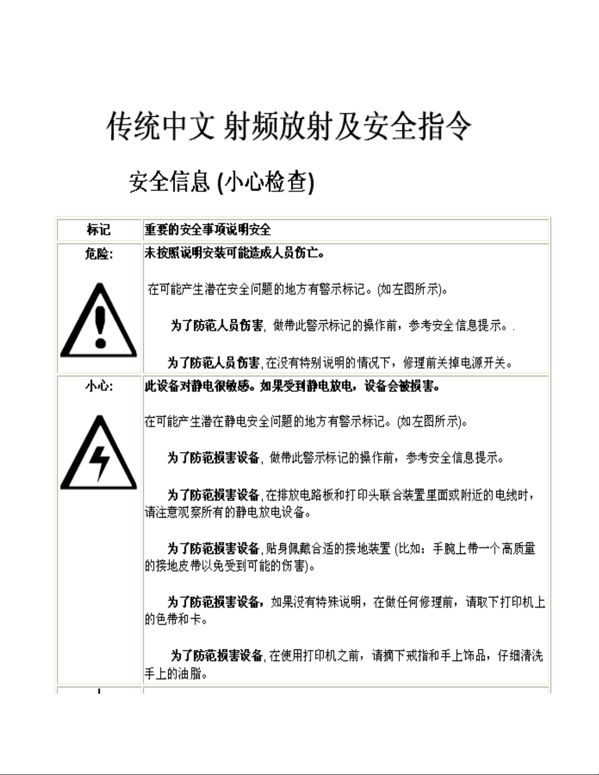
Traditional Chinese RF Emissions and Safety Statements
HDP8500 Industrial Card Printer/Encoder User Guide L001617 rev 1.1
11
Page 12

© 2012 HID Global Corporation. All rights reserved.
符号
涉及安全的重要过程
危险:
如果不遵循这些安装指南进行操作,可能会导致重伤,甚
至死亡。
可能引发安全问题的信息由警告符号(如左图所示)来表
示。
为了确保人身安全,在执行前面带有此符号的操作之
前,请先阅读下面的安全消息。
为了确保人身安全,除非另有规定,否则在执行维修过
Taiwan Traditional Chinese
經型式認證合格之低功率射頻電機,非經許可,公司、商號或使用者均不得
擅自變
更頻率、加大功率或變更原設計之特性及功能。低功率射頻電機之使用不得
影響飛
航安全及干擾合法通信;經發現有干擾現象時,應立即停用,並改善至無干
擾時方
得繼續使用。前項合法通信,指依電信法規定作業之無線電通信。低功率射
頻電機
須忍受合法通信或工業、科學及醫療用電波輻射性電機設備之干擾。
China Simplified Chinese
安全消息(请仔细阅读)
HDP8500 Industrial Card Printer/Encoder User Guide L001617 rev 1.1
12
Page 13

© 2012 HID Global Corporation. All rights reserved.
程前,始终应断开电源。
小心:
此设备为静电敏感设备。如果暴露在静电电流下,可能会
损坏设备。
可能引发静电安全问题的信息由警告符号(如左图所示)
来表示。
为了防止设备或介质受损,在执行前面带有此符号的操
作之前,请先阅读下面的安全消息。
为了防止设备或介质受损,请在处理电路板和打印头部
件中或附近的电缆时,遵守所有规定的静电放电 (ESD)
过程。
为了防止设备或介质受损,请始终佩带适当的个人接地
设备(例如,已接地避免出现潜在损坏的高质量腕
带)。
为了防止设备或介质受损,除非另有规定,否则在执行
任何维修过程前,始终应将色带和证卡与打印机分离。
为了防止设备或介质受损,在操作打印机前,请取下手
指和手上的珠宝饰物,并将手上的油渍和污渍彻底清洗
干净。
HDP8500 Industrial Card Printer/Encoder User Guide L001617 rev 1.1
13
Page 14

© 2012 HID Global Corporation. All rights reserved.
Japan
この装置は総務省の型式指定を受けています。"
(総務省指定番号は第 AC-xxxxx号です)
本製品は電波を使用した RFID 機器の読み取り・書き込み装置です。
そのため使用する用途・場所によっては、医療機器に影響を与える恐れが
あります
Korean
HDP8500 Industrial Card Printer/Encoder User Guide L001617 rev 1.1
14
Page 15
© 2012 HID Global Corporation. All rights reserved.
Print Method
HDP Dye-Sublimation/ Resin Thermal Transfer
Print Resolution
300 dpi (11.8 dots per mm)
Print Colors
Up to 16.7 million and 256 shades per pixel
Print Ribbon Options
HDP8500 (prints or images):
Full-color, YMC*, 750 prints
Full-color with resin black, YMCK*, 500 prints
Full-color with two resin black panels, YMCKK*, 500 prints
Full-Color – Half Panel YMCK*, 1000 prints
Full-color with resin black and heat seal panel for difficult-
to-print surfaces, YMCKH*, 500 prints
Full-color with resin black and inhibit panel for signature or
other non-printing areas, YMCKI*, 500 prints
Full-color with fluorescing and resin black, YMCFK*, 500
prints
Resin black, K, 3000 prints
* Indicates the Ribbon type and the number of Ribbon panels
printed where Y=Yellow, M=Magenta, C=Cyan, K=Resin
Black, H=Heat Seal , I= Inhibit, and F=Fluorescing
HDP Film Options
System Capability - HDP Film Options:
Clear (1,500 prints)
Standard Holographic (500 prints)
Custom Holographic, special order (500 prints)
Overlaminate Options
Overlaminate options:
Thermal Transfer Overlaminate, .25 mil thick, 500 prints
PolyGuard® Overlaminate, 1.0 mil and .6 mil thick, 250
prints (PolyGuard available in a CR-80 patch size)
All overlaminates available in clear, standard holographic
design or custom holographic design
Print Speed in Batch
Mode-Normal mode
Batch Mode:
Performance
Normal
Technical Specifications
HDP8500 Industrial Card Printer/Encoder User Guide L001617 rev 1.1
15
Page 16

© 2012 HID Global Corporation. All rights reserved.
Print Mode
Mode
YMC
24 seconds
per card/ 150
cards per hour
29 seconds
per card/ 124
cards per
hour
YMCK
29 seconds
per card/ 124
cards per hour
35 seconds
per card/ 103
cards per
hour
YMCKK
40 seconds
per card/ 90
cards per hour
49 seconds
per card/ 73
cards per
hour
YMCK+Lam
34 seconds
per card/ 106
cards per hour
40 seconds
per card/ 90
cards per
hour
YMCKK+Lam
48 seconds
per card/ 75
cards per hour
55 seconds
per card/ 65
cards per
hour
Power Source
Voltage, Amp &
Frequency
Supply Voltage/Amp:
100-240 VAC, 3.5 A MAX
Supply Frequency:
50 Hz and 60 Hz
Power Supply
Printer- two (2) internal heavy duty power supplies
Laminator- one (1) internal heavy duty power supply
Dual Input Hopper
Two (2) Input Hoppers included:
Input Hopper supports 200 count card each
Card Exception Feed
standard
Card Input Capacity
400 – (.030” / .762 mm) cards
(Dual input Hoppers with 200 cards each)
Card Output Capacity
Concealed/tinted output bin, lockable access and attachment
to printer , 200 card minimum
.030” ( 30 mil) to .050” (50 mil) (.762 mm to 1.27 mm)
HDP8500 Industrial Card Printer/Encoder User Guide L001617 rev 1.1
16
Page 17
© 2012 HID Global Corporation. All rights reserved.
Reject Area Capacity
15 cards capacity, lockable (.030” and .762mm)
Card Materials and
Types
ABS
Laminated PVC
PET
PETG
Proximity
Smart Cards
Mag Stripe cards
Optical memory cards
Polycarbonate
Card Thickness
System will be compatible with card thicknesses from 20-
50 mil
Print only: .020” (20 mil) to .050” (50 mil) / .762mm to
1.27mm
Print/Lamination: .030” (30 mil) to .050” (50 mil) / .762mm
to 1.27mm
Card Sizes Supported
CR-80 (3.452”L x 2.204”W and 87.7mmL x 56mmW).
Memory
32 MB RAM
Card Cleaning Roller
Automatically cleans cards for higher print quality.
Replaceable biodegradable cleaning roller
Card Cleaning
Printer will use 2 integrated cleaning stations.
Laminator will use 3 integrated cleaning station.
Cleaning Prompt
3000 cards default. Interval is adjustable.
Display
3.2 “ Touchscreen Graphical Display
MS Windows
Compatibility
Windows XP
Server 2003
Vista (32 & 64 bit)
Windows Server (32 & 64 bit)
Windows 7 (32 & 64 bit)
Windows 2008 R1 R2
HDP8500 Industrial Card Printer/Encoder User Guide L001617 rev 1.1
17
Page 18
© 2012 HID Global Corporation. All rights reserved.
Magnetic Stripe
Encoding (Options)
Dual high- and low-Coercivity
Tracks 1, 2 and 3
ISO Mag Encoding
JIS 2 Mag Encoding
Custom Encoding
Raw Binary Encoding
E card
Omnikey 5125 Proximity Encoder
Omnikey 5121 Encoder
Magnetic Encoder
Contact Encoder
Single Wire Encryption
Options
Contactless Smart Card Encoder (HID iCLASS and
MIFARE)
Contact Smart Card Encoder reads from and writes to all
ISO7816-1 and 2 and 3 and 4 memory and microprocessor
smart cards (T=0, T=1) as well as synchronous cards
Prox Card Reader (HID read-only)
Encryption
AES-256 data
USB Connection
USB 2.0 standard
Ethernet Connection
Ethernet standard
System Requirements
x86 based PC or compatible, Windows XP, Windows 2003,
Windows Vista, Windows 2008, or Windows 7
500MHz computer with 256MB of RAM or higher,
500MB free hard disk space or higher
Operating Conditions
Operating Temperature: 65° to 90° F and 18° to 32° C
Humidity: 20 - 80% non-condensing
Dimensions
28.2 “ width x 14.0 “ depth x 15.5” height –Printer only
Ship Weight
Printer: 61 lbs. Laminator: 30 lbs.
Warranty
Printer- 3 years
Printhead Lifetime ; unlimited passes
Extended Warranty available
No On-Call Express offered
HDP8500 Industrial Card Printer/Encoder User Guide L001617 rev 1.1
18
Page 19
© 2012 HID Global Corporation. All rights reserved.
Component
Description
Card Cartridge
Load blank cards into this Cartridge.
Card Output
Hopper
Stores 200 cards.
Card
Lamination
Module
Works in conjunction with the Printer to apply a variety of different
overlaminates to printed cards, providing increased card durability
and security.
Will laminate in either the single or dual side (simultaneous) process
(Note: When printing a batch of cards, the Printer can be encoding
and printing one card while the Lamination Module laminates another
card.)
Display
3.2” AVGA TFT LCD w/ Resistive Touch Overlay
Printhead
The component of the Printer that actually does the printing.
USB Interface
Connect to the Windows PC USB port
Hardware
Accessories &
Connectivity
Each model has multiple cords and connectors.
US power cord
EU power cord
USB cable (2.0)
Ethernet
Print Modes
There are two print modes (Performance and Normal )
Normal print mode (default)
Performance print mode is faster with lower image quality and is
most suitable for minimal color with mostly resin text.
Resin Scramble
(OPTIONAL)
The system can hide any information printed with the resin panel.
Edge-to-Edge
Printing
Prints over the edge on CR-80 cards.
Color Profile
System Color Management & None
Functional Specifications
HDP8500 Industrial Card Printer/Encoder User Guide L001617 rev 1.1
19
Page 20

© 2012 HID Global Corporation. All rights reserved.
Card Flattener
(OPTIONAL)
Fully adjustable temp dwell
The card flattening routine occurs after the card is transferred but
before lamination.
The card flattener has an adjustable temp and dwell.
You can select from different offset values from the default temp.
You can select from different offset values from the default dwell.
The card flattener has a 0 to 15 second adjustable delay before
the flattening routine will run.
The driver can disable the card flattener, if a dual sided job is
sent.
Recommended for heat sensitive PVC cards.
Locks
Hardware locks are a standard feature.
Mechanical and key locks are used to secure the doors on the
input card cartridges, the access door to the printer, the access
door to the Laminator and the output card Hopper.
The input card cartridges are manually secured to the printer
mechanism via toggle latch located inside the access door of the
printer.
The Printer and Laminator include a compatible hole with a
Kensington lock.
The printer and Laminator include threaded hardware.
Andon Light
(OPTIONAL)
4-Color Andon Light option. Each color is controlled separately. The
four colors indicate the following:
Red: A printer error has occurred or operator intervention is
needed.
Blue: Printer has run out of materials (film, ribbon or cards)
Green: Normal Printer operation.
Orange: User intervention is needed soon. Printer materials are
low or the printer needs to be cleaned.
HDP8500 Industrial Card Printer/Encoder User Guide L001617 rev 1.1
20
Page 21
© 2012 HID Global Corporation. All rights reserved.
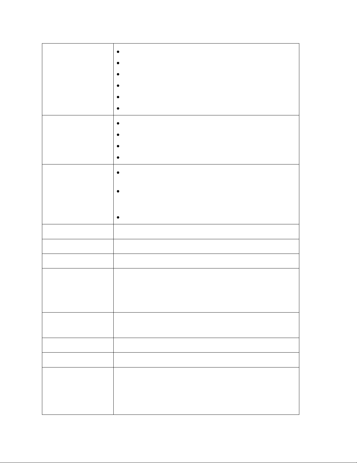
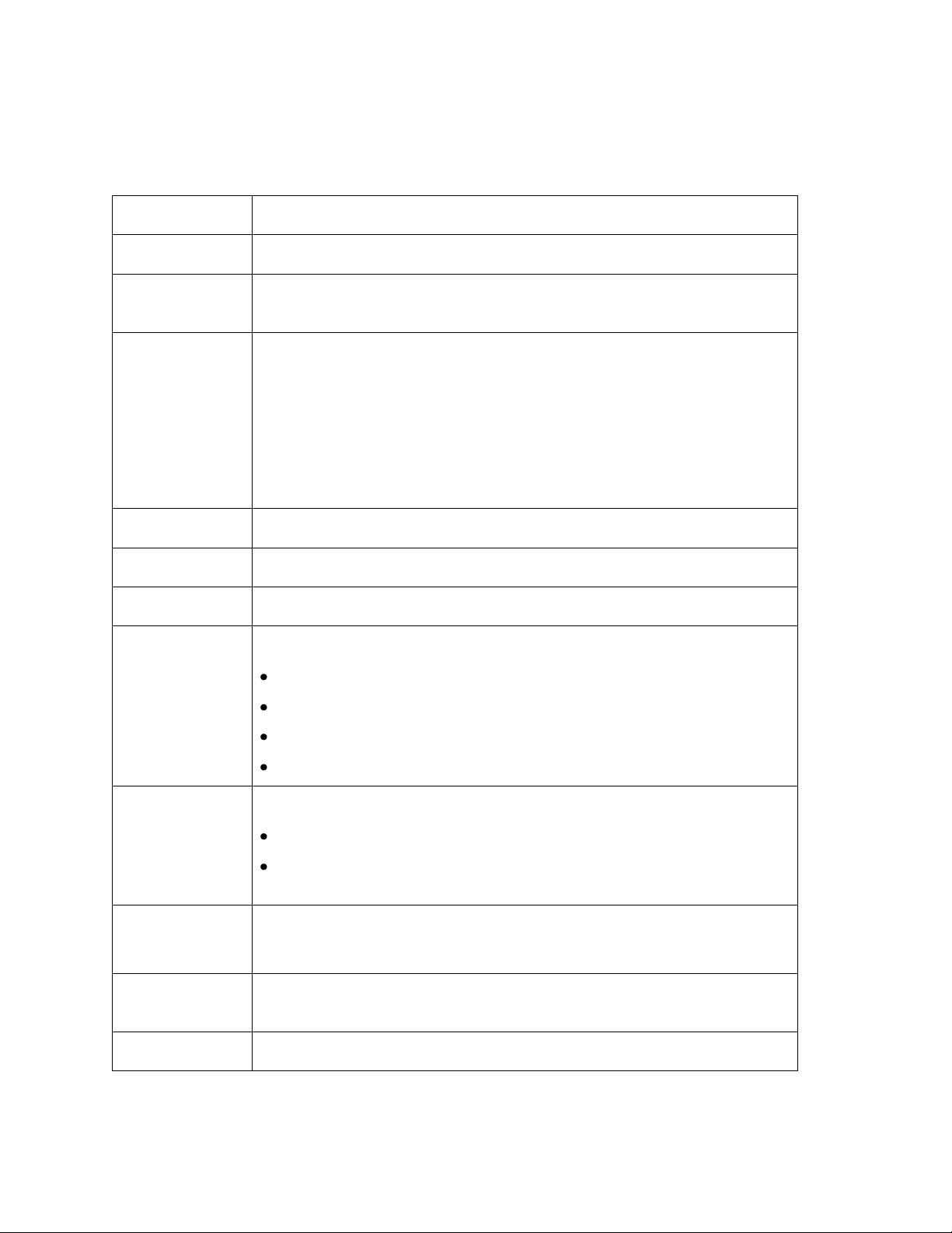
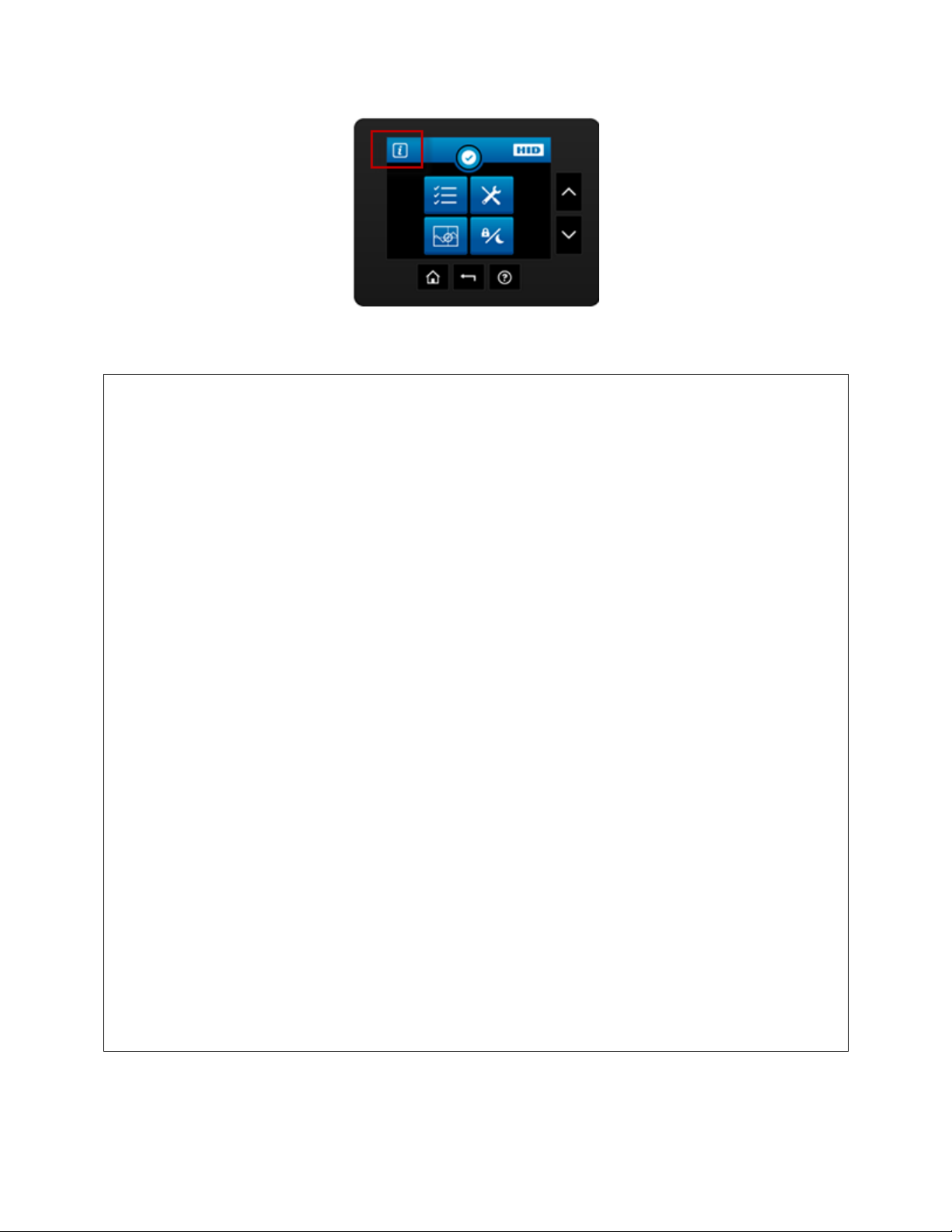
Click this icon to get to the System Information Screen
System Information Screen Option.
This is the Notification Icon which shows status and error
messages
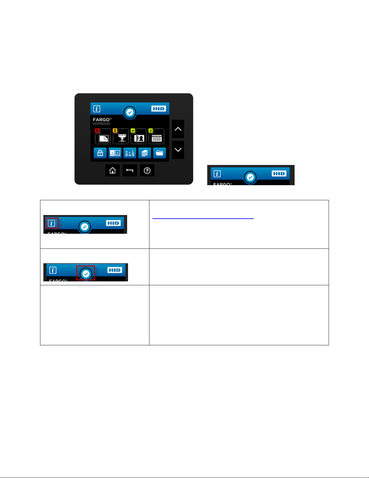
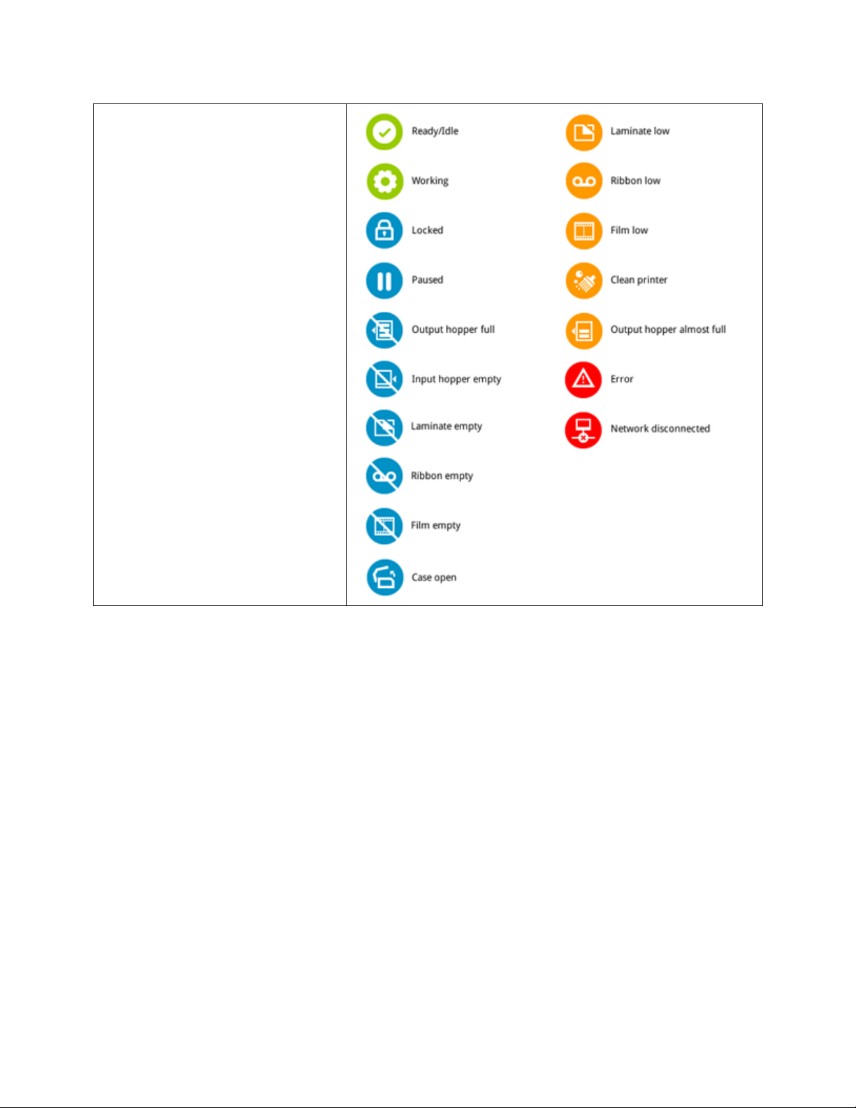
Notification Icons
These are the icons displayed in the notification area.
Section 2: Graphical Display
Home Screen
HDP8500 Industrial Card Printer/Encoder User Guide L001617 rev 1.1
21
Page 22
© 2012 HID Global Corporation. All rights reserved.
22
HDP8500 Industrial Card Printer/Encoder User Guide L001617 rev 1.1
Page 23
© 2012 HID Global Corporation. All rights reserved.
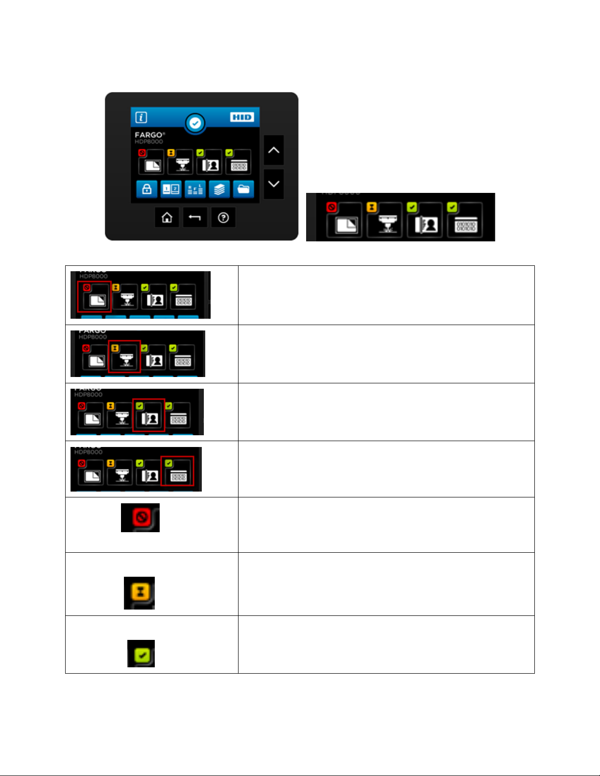
Laminator configuration (if displayed is installed)
Laser Engraver (if displayed is installed)
HID Printer
Encoder (if displayed is installed)
Icon shows status is PROBLEM
Press the Station icon to open the Station Details screen,
which provides more detail about the station status.
Icon shows status is BUSY
Press the Station icon to open the Station Details screen,
which provides more detail about the station status.
Icon shows status is READY
Press the Station icon to open the Station Details screen,
which provides more detail about the station status.
Home Screen ( continued)
HDP8500 Industrial Card Printer/Encoder User Guide L001617 rev 1.1
23
Page 24
© 2012 HID Global Corporation. All rights reserved.
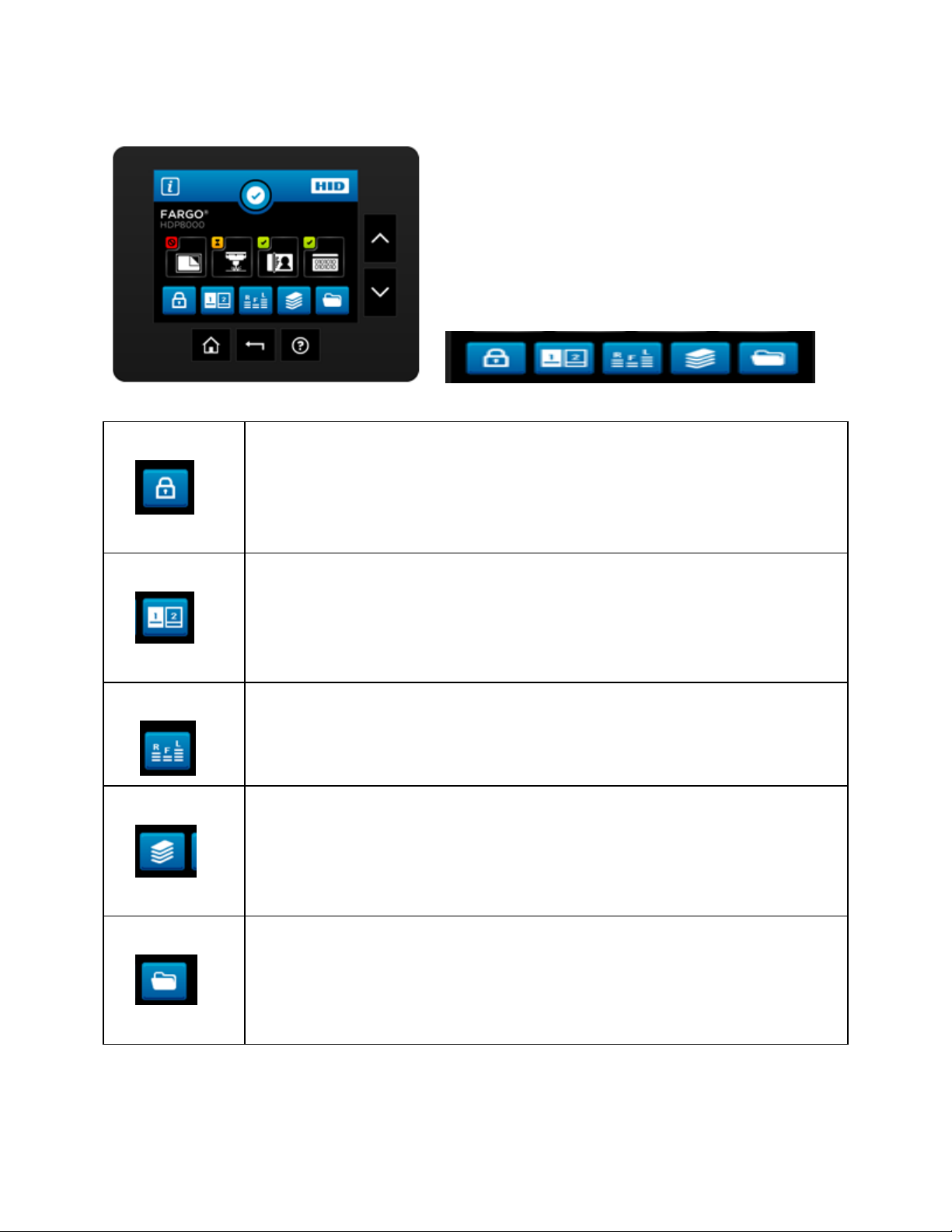
Printer lock
Hopper Select
Ribbon Film Laminate levels shown
Card Count
Setup Menu
Home Screen ( continued)
HDP8500 Industrial Card Printer/Encoder User Guide L001617 rev 1.1
24
Page 25
© 2012 HID Global Corporation. All rights reserved.
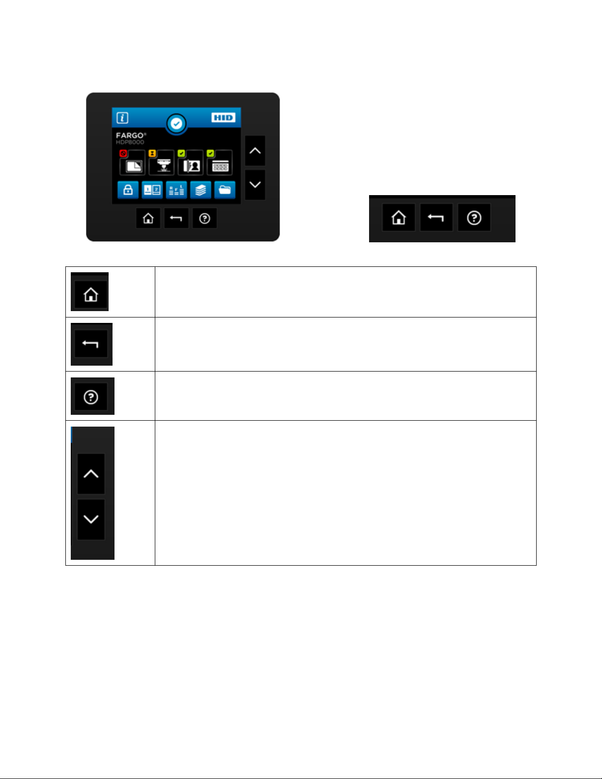
Home Screen
Back one level
HELP
The side buttons allow vertical scrolling when the current screen
accommodates multiple lines.
Home Screen ( continued)
HDP8500 Industrial Card Printer/Encoder User Guide L001617 rev 1.1
25
Page 26
© 2012 HID Global Corporation. All rights reserved.
Note: Select the desired option to view information
Serial Number
Model Name
Printer Firmware
Laminator Firmware
Display Firmware
MAC Address
IP Address
Ribbon Type
Film Type
Lam 1 Type
Lam 2 Type
Mag Encoder
Smart Encoder
Prox Encoder
Mifare Encoder
iCLASS Encoder
Laminator
Flipper
Card Count
Pass Count
Transfer Count
System Information Screen Option
HDP8500 Industrial Card Printer/Encoder User Guide L001617 rev 1.1
26
Page 27
© 2012 HID Global Corporation. All rights reserved.
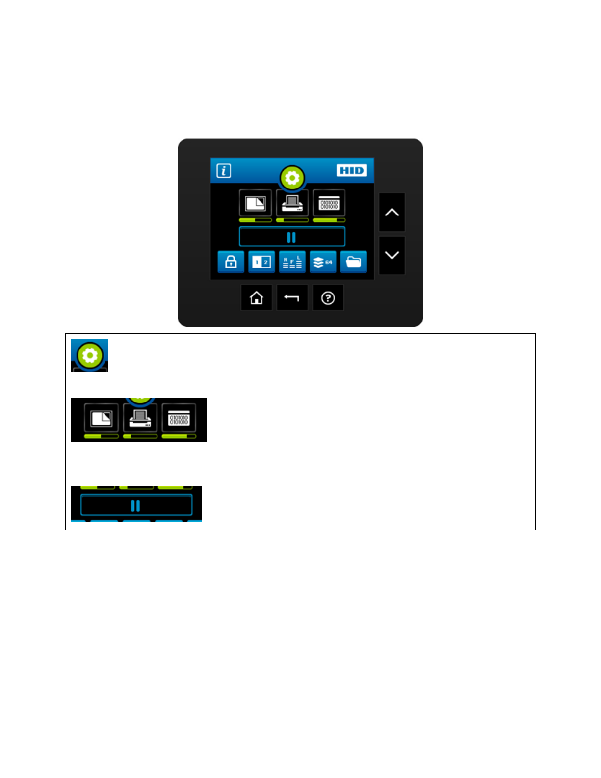
While the printer is working, the Notification icon shows a moving gear .
Each Station icon shows a progress bar with its current progress
in the job
A global pause button is shown.
Process Status
HDP8500 Industrial Card Printer/Encoder User Guide L001617 rev 1.1
27
Page 28
© 2012 HID Global Corporation. All rights reserved.
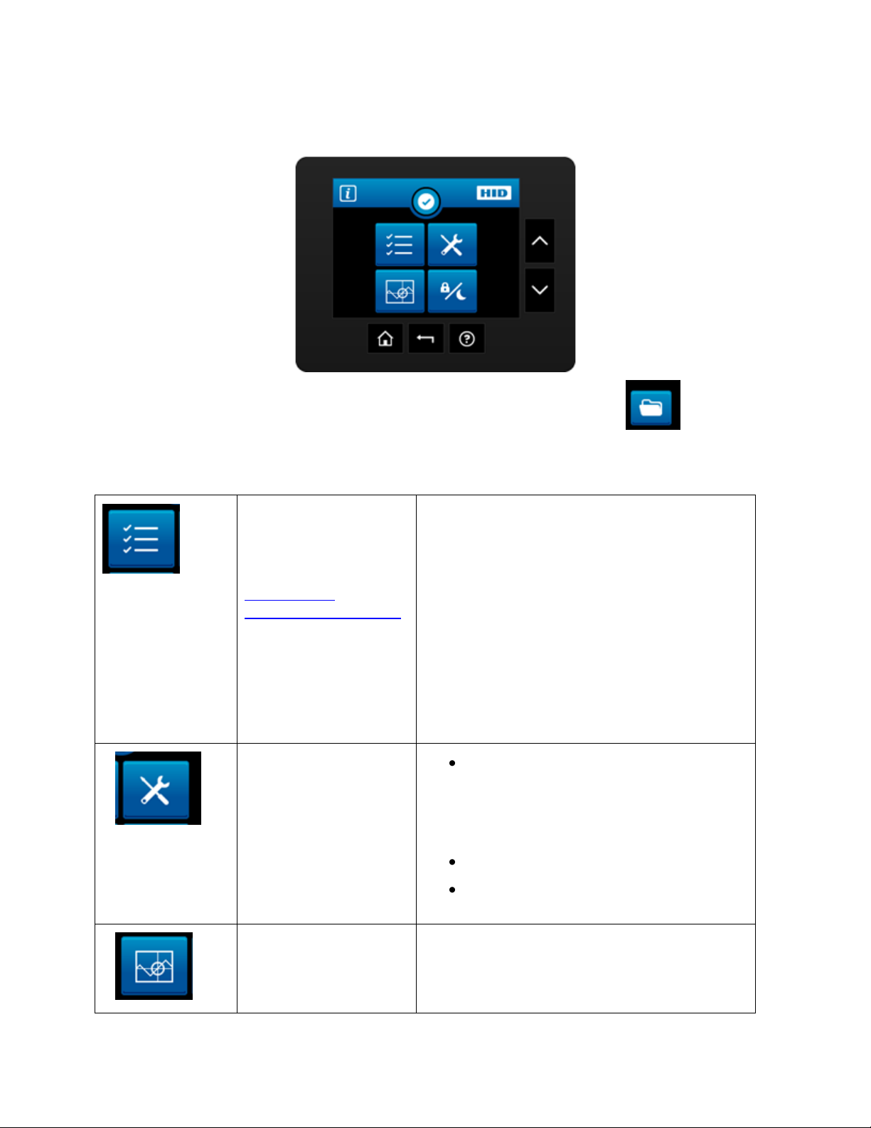
Printer Settings
For details see:
Selecting the
Advanced Settings tab
Printer
Transfer
Laminator
Mag Encoding
Flipper
Hopper (see Display A below for details)
Display
Network
Language
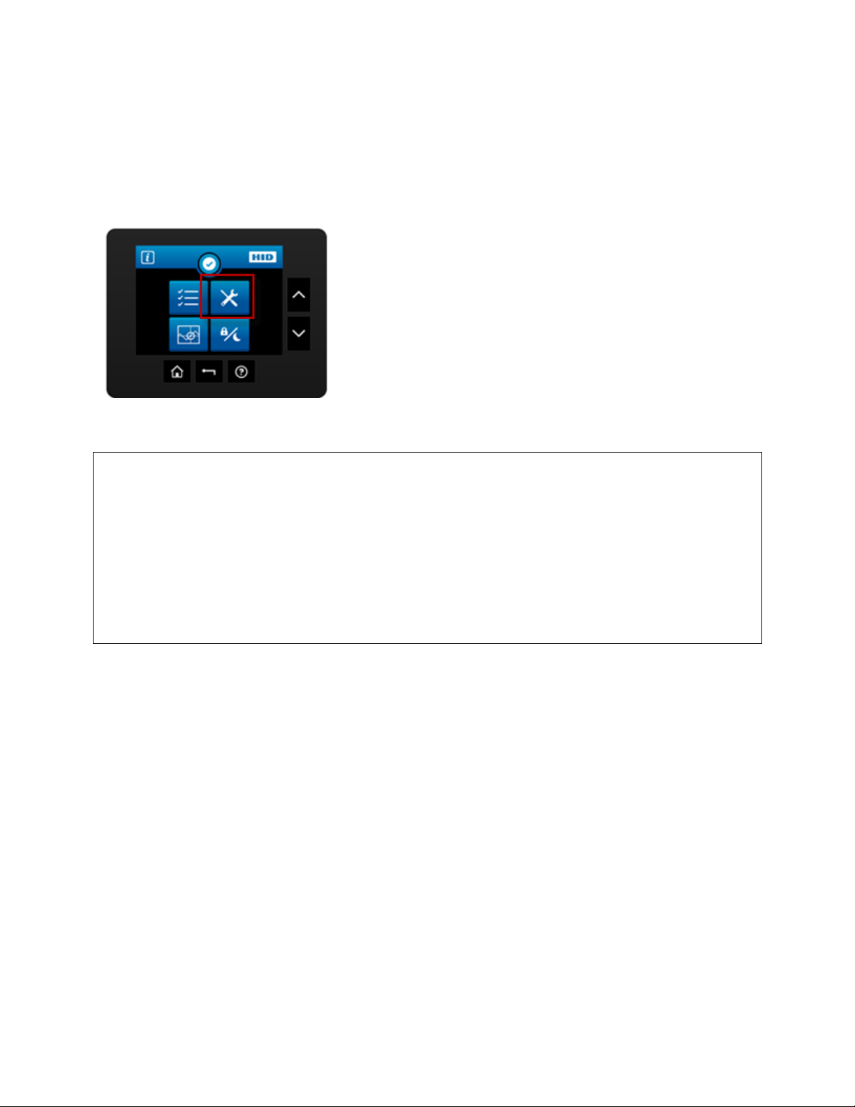
Tools
Diagnostics
Self Test (see Display B below for details)
Mechanical Test (see Display C below for
details)
Cleaning the Printer
Firmware Upgrade (use the
Workbench Utility Program)
Sensor Calibration
Calibration ( see Display D below for details)
Ribbon Sensor
Main Menu
Press the Setup Menu Icon on the Home Screen to access the Main Menu
Icon Name Options Included
HDP8500 Industrial Card Printer/Encoder User Guide L001617 rev 1.1
28
Page 29
© 2012 HID Global Corporation. All rights reserved.
Film Sensor
Mag Sensor
Lamination Sensor
Lock and Sleep
settings
See Display E below for details
Sleep Time
Stand-by Time
Stand-by Temp
Display Sleep Time
Change password
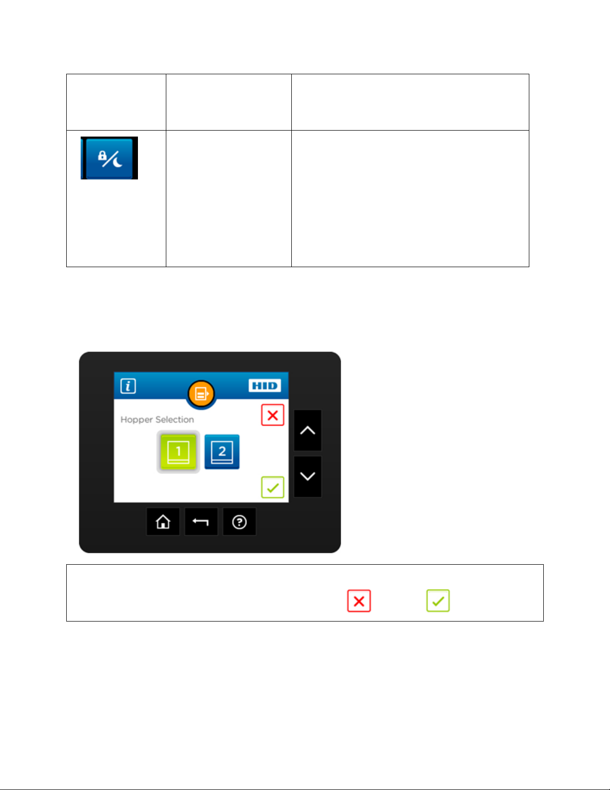
Hopper selection screen allows the user to change the hopper where cards are fed from.
Green indicates the selected hopper, also shows cancel and save buttons.
Main Menu (continued)
Hopper Selection
Display A
HDP8500 Industrial Card Printer/Encoder User Guide L001617 rev 1.1
29
Page 30
© 2012 HID Global Corporation. All rights reserved.
Alignment Test
YMC Color Bar Test
Magnetic Test
YMCK Test
Standard Resin Test
Printer Settings card
Color Photo Test
Main Menu (continued)
Display B
Tools –Diagnostic Self Test Options
HDP8500 Industrial Card Printer/Encoder User Guide L001617 rev 1.1
30
Page 31

© 2012 HID Global Corporation. All rights reserved.
When selected the printer will perform the test to verify mechanical options are working
correctly
Lower Printhead
Raise Printhead
Home Flipper Table
Run ribbon take-up motor
Run ribbon supply motor
Run Printhead lift motor
Cycle transfer head lift motor
Run film supply motor
Run film take-up motor
Main Menu (continued)
Display C
Tools –Diagnostic Mechanical Test Options
HDP8500 Industrial Card Printer/Encoder User Guide L001617 rev 1.1
31
Page 32

© 2012 HID Global Corporation. All rights reserved.
NOTE: Calibrating sensors may be done through the Driver Printing Preferences Toolbox OR
through the LCD DISPLAY. Both options use the same printer setup information.
Ribbon Sensor Calibration
Film Sensor Calibration
Magnetic TOF ( Top of Form)
Lamination Sensor Calibration
Main Menu (continued)
Display D
Sensor Calibration Options
32
HDP8500 Industrial Card Printer/Encoder User Guide L001617 rev 1.1
Page 33

© 2012 HID Global Corporation. All rights reserved.
Select to desired option and use the + and – button to adjust the number.
Cancel revert save buttons
Sleep Time
Standby Time
Standby Temp
Display Sleep Time
Change Password
Main Menu (continued)
Display E
Sleep and Lock Settings
Case Open
HDP8500 Industrial Card Printer/Encoder User Guide L001617 rev 1.1
33
Page 34

© 2012 HID Global Corporation. All rights reserved.
When the cover is opened, this screen is presented.
The arrows ( ) allow card shuttle from 1 to 2
The arrows() ) move the rollers back and forth. This is used if a card jam occurs.
When an error occurs a details screen appears, containing details about the specific error that
occurred.
The keys to the right are:
Job Cancel
Station Error
HDP8500 Industrial Card Printer/Encoder User Guide L001617 rev 1.1
34
Page 35

© 2012 HID Global Corporation. All rights reserved.
Retry
Help
While adjusting settings in the setting menu, the Boolean setting can be set by pressing the
desired value.
Green indicates the selected setting.
Boolean Setting
Settings Keypad
HDP8500 Industrial Card Printer/Encoder User Guide L001617 rev 1.1
35
Page 36

© 2012 HID Global Corporation. All rights reserved.
While setting a value in the settings menu that requires numeric input, a keypad will be
presented.
Current value is displayed in blue font.
Cancel and save buttons
Blue instructions says: "Enter Current PIN" Button says: "Next >"
Blue instructions says: "Enter New PIN" Button says: "Next >"
Blue instructions says: "Confirm New PIN" Button says: "Enter"
Pin Keypad
HDP8500 Industrial Card Printer/Encoder User Guide L001617 rev 1.1
36
Page 37

© 2012 HID Global Corporation. All rights reserved.
When the printer is to be locked or unlocked the Security Keypad is presented.
Enter the PIN and press Enter.
While setting a value in the settings menu that requires a selection, this screen will be
presented.
Current value is highlighted in green.
Cancel and save buttons
Security Keypad
Text Button Select
HDP8500 Industrial Card Printer/Encoder User Guide L001617 rev 1.1
37
Page 38

© 2012 HID Global Corporation. All rights reserved.
Navigate to the Notification list by pressing on the Notification Icon.
This will show the notification detail and allow navigation to further details.
Navigate to a printer settings menu, a list of all settings will be displayed.
Scroll up and down using the side buttons, make selections by pressing the specific setting‟s
button.
Notification List
Menu Detail List
HDP8500 Industrial Card Printer/Encoder User Guide L001617 rev 1.1
38
Page 39

© 2012 HID Global Corporation. All rights reserved.
Consumables status screen shows current levels for :
Laminate supply
Film supply
Ribbon supply
While setting a value in the settings menu that requires an integer input, this screen will be
presented.
Current value is displayed and can be incremented or decremented by the + or – keys
respectively.
Consumable Status
Integer Selection
HDP8500 Industrial Card Printer/Encoder User Guide L001617 rev 1.1
39
Page 40

© 2012 HID Global Corporation. All rights reserved.
Cancel revert save buttons
Some settings require a confirmation.
to Decline or to Accept.
Card counter screen allows the user to view the total number of cards printed as well as the
Current count for a particular batch.
Confirmation
Card Counter
HDP8500 Industrial Card Printer/Encoder User Guide L001617 rev 1.1
40
Page 41

© 2012 HID Global Corporation. All rights reserved.
The current count can be reset to zero by pressing the reset key.
Help screen (in the future) will provide detailed information for recovering from common errors.
Help Screen
HDP8500 Industrial Card Printer/Encoder User Guide L001617 rev 1.1
41
Page 42

© 2012 HID Global Corporation. All rights reserved.
Section 3: Setup and Installation Procedures
Inspection – HDP8500
While unpacking your Printer, inspect the carton to ensure that no damage has occurred during
shipping. Make sure that all supplied accessories are included with your unit.
Unpacking the Printer.
The following items are included with your Printer:
Software Installation CD (includes Printer Driver, Online User‟s Guide and Printer Diagnostic
Tool)
Power Cord
Card Cleaning Roller (x2)
Card Cartridge (x2)
Card Output Bin
Ribbon Cartridge
Film Cartridge
Warranty Statement
This is included with the HDP8500-LC Only:
Card Lamination Module
(Important: Please use the original packaging when shipping the HDP8500 Printer/Laminator.
This will require the Laminator Module to be detached from the Printer prior to shipping.)
Choosing a Good Location
Follow these guidelines:
Place the unit in a location with adequate air circulation to prevent internal heat build-up.
Use the Printer's dimensions as a guideline for the minimum clearances to the unit. (Note:
Allow for adequate clearance above the unit to accommodate the height of the unit with its
Covers open.)
Do not install unit near heat sources such as radiators or air ducts or in a place subject to
direct sunlight, excessive dust, mechanical vibration or shock.
About Moisture Condensation
If the unit is brought directly from a cold to a warm location or is placed in a very damp room,
moisture may condense inside the unit. Should this occur, print quality may not be optimum.
Leave the unit turned OFF in a warm, dry room for several hours before using. This will allow
the moisture to evaporate.
HDP8500 Industrial Card Printer/Encoder User Guide L001617 rev 1.1
42
Page 43

© 2012 HID Global Corporation. All rights reserved.
Step
Procedure
1
Unlock and open the Printer cover .
2
Remove the HDP Film Cartridge.
Loading the HDP Transfer Film
Note: Fargo Card Printers require highly specialized supplies to function properly.
To maximize Printer life, reliability, printed card quality and durability, you must use only
Fargo Certified Supplies.
For this reason, your Fargo warranty is void, where not prohibited by law, if you use non-
Fargo Certified Supplies.
HDP8500 Industrial Card Printer/Encoder User Guide L001617 rev 1.1
43
Page 44

© 2012 HID Global Corporation. All rights reserved.
3
Load the HDP Film into the Film Cartridge and click into place.
The green take-up spool goes on the left side, the full roll goes on the right
side. 4
Tighten the HDP Film.
5
Insert the HDP Film cartridge back into the printer and click into place.
44
HDP8500 Industrial Card Printer/Encoder User Guide L001617 rev 1.1
Page 45

© 2012 HID Global Corporation. All rights reserved.
Step
Procedure
1
Unlock and open the Printer cover .
2
Remove the HDP Ribbon Cartridge.
3
Load the HDP Ribbon into the Cartridge and click into place.
The blue take-up spool goes on the left side, the full roll goes on the right side.
Loading the Ribbon
HDP8500 Industrial Card Printer/Encoder User Guide L001617 rev 1.1
45
Page 46

© 2012 HID Global Corporation. All rights reserved.
4
Tighten the Ribbon .
5
Insert the HDP Ribbon cartridge back into the printer and click into place.
6
Insert the HDP Ribbon cartridge back into the printer and click into place.
HDP8500 Industrial Card Printer/Encoder User Guide L001617 rev 1.1
46
Page 47

© 2012 HID Global Corporation. All rights reserved.
Step
Procedure
1
Unlock and open the Printer cover .
2
Remove the Card Cleaning Roller from the Print Ribbon packaging and insert
the Cleaning Roller into the gray handle.
3
Remove the protective sleeve from the Card Cleaning Roller.
Loading the Card Cleaning Roller
The HDP8500 contains 2 card cleaning assemblies in the Printer and 1 cleaning assembly in
the Lamination Module. Use the same procedure for both.
HDP8500 Industrial Card Printer/Encoder User Guide L001617 rev 1.1
47
Page 48

© 2012 HID Global Corporation. All rights reserved.
4
Insert the Card Cleaning Roller assembly into the card cleaning slot.
5
Follow the same procedure for the second cleaning assembly.
6
Follow the same procedures for the Lamination Module assembly.
HDP8500 Industrial Card Printer/Encoder User Guide L001617 rev 1.1
48
Page 49

© 2012 HID Global Corporation. All rights reserved.
Step
Procedure
1
Unlock and open the Printer cover .
2
Remove the HDP Lamination Cartridge from the Printer.
3
Load the HDP Lamination into the Cartridge and click into place.
4
Tighten the HDP Laminate.
Loading the Overlaminate
(Note: This procedure only applies to the HDP8500-LC.)
The loading process for both the Thermal Transfer Overlaminate and the PolyGuard™
Overlaminate material is the same. Refer to the following steps to load either type of
overlaminate into the Printer.
HDP8500 Industrial Card Printer/Encoder User Guide L001617 rev 1.1
49
Page 50

© 2012 HID Global Corporation. All rights reserved.
5
Insert the HDP cartridge back into the printer and click into place.
HDP8500 Industrial Card Printer/Encoder User Guide L001617 rev 1.1
50
Page 51

© 2012 HID Global Corporation. All rights reserved.
Step
Procedure
1
Unlock and open the Card Input Cartridge.
Leave the cartridge in the Printer, There is no need to completely remove the
cartridge to load cards.
2
Load the cards into the cartridge.
Important: The front of the card must face DOWN. The back of the card
or the magnetic stripe on the card must face UP. The Smart Chip is
loaded on the bottom.
3
Place the Card Weight on top of each stack of cards.
Loading the Blank Cards
HDP8500 Industrial Card Printer/Encoder User Guide L001617 rev 1.1
51
Page 52

© 2012 HID Global Corporation. All rights reserved.
4
Close and lock the Card Input Cartridge.
5
To completely remove the Card Input Hopper unlock the Printer Top Cover
and release the BLUE lever to unlock the individual hopper.
HDP8500 Industrial Card Printer/Encoder User Guide L001617 rev 1.1
52
Page 53

© 2012 HID Global Corporation. All rights reserved.
Step
Procedure
1
Unlock and place the card output hopper onto the output side ( left) of the
printer and push down until it clicks into place.
Step
Procedure
1
Insert the power cord into the Printer as shown below.
2
Use the ON/Off switch to power up and down. This powers up both the Printer and the
Lamination Module.
Installing the Card Output Hopper
Connecting Power to HDP8500 Printer and/or Lamination
Module
Important! Do not plug in the USB cable until prompted to do so during the installation of the
HDP8500 Printer Driver. Refer to the Driver installation procedure below.
HDP8500 Industrial Card Printer/Encoder User Guide L001617 rev 1.1
53
Page 54

© 2012 HID Global Corporation. All rights reserved.
Step
Procedure
1
Close down all programs.
Insert the Software Installation CD into your computer‟s CD drive. After a few
seconds, the CD‟s installer program will automatically open.
Follow the CD‟s on-screen Procedures to complete installation.
(Note: If the CD does not automatically open, use “My Computer” or
“Windows Explorer” to view the contents of the CD. Then, double-click on the
Setup.exe file listed on the CD.)
2
Click NEXT and follow the screen prompts to complete the driver installation.
Printer Driver Installation Procedures
(For MAC OS X and Linux Driver and User Guide see www.hidglobal.com
HDP8500 Industrial Card Printer/Encoder User Guide L001617 rev 1.1
54
Page 55

© 2012 HID Global Corporation. All rights reserved.
Section 4: Printer Driver Operations
See this section for printer adjustments.
Using the Card tab
HDP8500 Industrial Card Printer/Encoder User Guide L001617 rev 1.1
55
Page 56

© 2012 HID Global Corporation. All rights reserved.
Step
Procedure
1
Select the appropriate card option:
These Card Printers accept standard CR80 sized cards
(3.452L x 2.204W / 87.7 mmL x 56 mmW)
CR-80: This selection is the default form size for the HDP8500
Custom: This selection is used to create a custom form size from 1.0 x
3.0 to 2.204 to 3.452 (25.4 X 76.2 mm to 56 X 87.7 mm).
The dimensions of the total print area for each card size will appear in the Print
Width and Print Length boxes.
These print area dimensions are .04" (1mm) larger than the actual card
size. This is so the Printer can overprint images to ensure they will appear
Edge-to-Edge when transferred to the card.
For this reason, when designing a card format, always set the card size or
page size within the card design program to the exact Print Length and
Width dimensions listed in the Printer Driver.)
Card
Thickness
System will be compatible with card thicknesses from 20-50 mil
Print only: .020” (20 mil) to .050” (50 mil) / .762mm to 1.27mm
Print/Lamination: .030” (30 mil) to .050” (50 mil) / .762mm to 1.27mm
Selecting the Card Size
Important! Never run cards with a contaminated, dull or uneven surface through the Printer.
Printing onto such cards will ultimately lead to poor print quality. Always store the card stock in
its original packaging or in a clean, dust-free container. Do not print onto cards that have been
dropped or soiled.
HDP8500 Industrial Card Printer/Encoder User Guide L001617 rev 1.1
56
Page 57

© 2012 HID Global Corporation. All rights reserved.
Step
Procedure
Card Type
You have these selections (to choose from):
Fargo UltraCard Premium III (Default Card Type) = 180˚ and 2
sec
Fargo Ultracard = 175˚and 2.0 sec
HID Tech Card Composite = 190˚ and 2 sec
HID Tech Card PVC =180˚and 2.0 sec
Indala FlexISO – Standard (FPISO) = 185˚and 2.0 sec
Indala FLexISO XT-Composite (FPIXT) 190˚ and 2 sec
Custom 1 = 175˚and 2.0 sec
Custom 2 = 175˚and 2.0 sec
Defaults: The HDP Printer Driver software has default Transfer
Temperature and Dwell Time settings that deliver the best
transfer for these card types. These defaults automatically
configure based on the card type, Ribbon type and whether
printing single- or dual-sided.
Card Type Selection: Before printing, if using these standard
Fargo card types, check to make sure that the appropriate card
type option selected from the Card tab of the HDP Printer
Driver:
Proper Settings: It is very important to note that not all card
types will be accommodated by these default settings. In some
cases, experimentation may be needed to find the proper
settings.
IMPORTANT: If the appropriate option is not selected, the wrong
Dwell Time and temperature may be used during the image transfer
process, which may result in poor adhesion of the HDP Film or
warping of the card.)
Card Design
The Printer will print onto any card with a clean, level and polished
PVC surface. (Important: Composite PVC is recommended over
straight PVC for the best results and for ISO card specification
compliance. Single-side straight PVC does not conform to ISO
compliance at this time.)
Card Surface
Suitable cards must have a polished PVC surface free of
fingerprints, dust or any other types of embedded contaminants.
Selecting the Card Type
Select the appropriate card type according to the composition of the card stock.
HDP8500 Industrial Card Printer/Encoder User Guide L001617 rev 1.1
57
Page 58

© 2012 HID Global Corporation. All rights reserved.
In addition, cards must have a completely smooth, level surface
in order for the Printer to achieve consistent color
CoverageSome types of Proximity cards, for example, have an
uneven surface which will inhibit consistent color transfer.
Likewise, some smart card chips are raised slightly above the
cards surface, which also results in poor color transfer.
UltraCard stock
Due to the importance of using high-quality blank cards, a factoryapproved card stock called UltraCard™ is available and
recommended for best results.
UltraCard stock has a glossy PVC laminate on top and bottom
and is optically inspected to provide the cleanest, most scratch
and debris-reduced cards possible.
Two types of these cards are available: UltraCard and UltraCard
Premium III.
UltraCard stock has a PVC core and offers medium card
durability.
Recommended: UltraCard Premium III stock has a 40%
polyester core and offers high durability.
Both types of UltraCards produce printed images with a glossy,
photo-quality finish.
Custom
If using a card stock other than listed, use the Custom 1options to
save custom Dwell Time and dwell temperature controls on the
Image Transfer tab.
a. Click on the Custom options and enter a name for the card
stock.
b. Click on the Image Transfer tab to adjust the Dwell Time and
temperature sliders to the appropriate settings. See the Display
A below. page. (Note: These settings will be saved for the
custom card type when the Printer Driver setup window is
closed.)
c. Custom Card stock: To determine the proper settings for
custom card stock, apply the Tape adhesion Test. Conducting
the Tape Adhesion Test.
HDP8500 Industrial Card Printer/Encoder User Guide L001617 rev 1.1
58
Page 59

© 2012 HID Global Corporation. All rights reserved.
Display A
Printing on Alternate Card Stocks
In order to optimize the HDP Card Printer‟s capabilities for cards with hard-to-print surfaces, we
recommend evaluating the card stock selection before installation of the Printer. The variability
in cards based on:
Different surface textures and different sources of raw materials: This may require
different HDP Film transfer parameters.
Varied methods of assembling IC smart cards and proximity cards: These particular
adhesives used to glue a smart chip to a plastic card may react differently to a Transfer
Roller‟s pressure and temperature.
Cleanliness of card stock: The HDP process does not eliminate the need to use clean
card stock. The best-looking card always starts with the cleanest card surface. Dirt and
debris on a card can show up as blemishes on the card surface and may reduce the life of
the image itself.
HDP8500 Industrial Card Printer/Encoder User Guide L001617 rev 1.1
59
Page 60

© 2012 HID Global Corporation. All rights reserved.
Step
Procedure
1
Test the adhesion quality of the HDP Film to the card by printing sample cards
and completing an adhesive tape test.
2
Select the UltraCard IIIs-Glossy PVC if the card is glossy and print a test card.
3
a. Apply a strip of ½ (12mm) wide Scotch-type clear adhesive tape (such as
3M brand 600), at least 2” (50mm) long, firmly across the surface of the
card, pressing out all air bubbles with a fingertip.
b. Remove the tape by smoothly and rapidly (approximately 2 inches/second
(50mm/sec)) pulling it up at a perpendicular (90 degree) angle to the card.
(Note: The IPC recommends a minimum of three tests for each card type
evaluation.)
4
Visually examine the card and the strip of tape pulled from the card, to see if
any portion of the HDP Film was removed from the card.
If any residue (e.g., oil or grease from fingertips) is present on the card
surface, the evaluation results may be affected.
If the printed, transferred HDP Film particles (a) pull away from the card
and (b) adhere to the tape, this indicates that inadequate adhesion of the
HDP Film to the card. Increased heat and Dwell Times are necessary to
resolve this problem.
Samples 1, 2 and 3 show a representation of the adhesion level you can
expect.
Result 1: Sample 1 shows a significant transfer to the tape and is an
absolute failure.
Result 2: Sample 2 shows that very slight transfer to the tape can be
acceptable without sacrificing overall image durability on matte finish cards.
Result 3: Sample 3 shows no transfer to the Tape and is an Absolute
Pass.
5
If the tape test indicates inadequate adhesion, increase the heat setting by 5
degrees, print another card and try the tape test again.
Conducting the Tape Adhesion Test
It is important to conduct tape adhesion tests because Fargo cannot be certain which transfer
temperature and Dwell Time will work best (when printing cards other than UltraCard III). (Note:
The optimal transfer settings may vary from card type to card type.)
Important! Inadequate time and temperature could produce cards that are more vulnerable to
accelerated wear and dye migration. Use sufficient time and temperature to transfer HDP Film
to the card to ensure a long lasting, durable card.
HDP8500 Industrial Card Printer/Encoder User Guide L001617 rev 1.1
60
Page 61

© 2012 HID Global Corporation. All rights reserved.
Once the temperature has been increased 4 times (20 degrees), reset
temperature to default and increase the Dwell Time by .5 second.
Repeat this process until adequate adhesion is achieved.
Ensure that the cards (in use) have a surface roughness (Ra) of 60 micro
inches or less.
This information should be available from the card manufacturer.
HDP8500 Industrial Card Printer/Encoder User Guide L001617 rev 1.1
61
Page 62

© 2012 HID Global Corporation. All rights reserved.
Step
Procedure
1
From the Printer Driver select the desired hopper from which to feed the
card.
2
From the Printer Ready screen select the HOPPER icon
3
Cycle between Hopper 1 and Hopper 2 by selecting 1 or 2 from the
Printers Display Control Panel.
Click to save
Using the Card Hopper Selection
Use this option to select the Card Input Hopper. There are 2 options for setting the Hopper.
HDP8500 Industrial Card Printer/Encoder User Guide L001617 rev 1.1
62
Page 63

© 2012 HID Global Corporation. All rights reserved.
Step
Procedure
1
Select Portrait to cause the card to print in a vertical orientation.
OR
Select Landscape to cause the card to print in a horizontal orientation.
Setting the Orientation
Select either the Portrait or Landscape radio buttons for Orientation.
HDP8500 Industrial Card Printer/Encoder User Guide L001617 rev 1.1
63
Page 64

© 2012 HID Global Corporation. All rights reserved.
Specifying the number of Copies
Specifies the number of copies to be printed.
The upper limit is 10000 and the lower limit is 1.
Selecting the Diagnostics button
This will launch the Diagnostic tool (if installed). The Workbench Utility Program is included on
the driver CD. Also see the Workbench Utility Program User Guide located on the driver CD..
HDP8500 Industrial Card Printer/Encoder User Guide L001617 rev 1.1
64
Page 65

© 2012 HID Global Corporation. All rights reserved.
Step
Procedure
1
Install a HDP8500 compatible ribbon in the Printer for the Test Print.
The ribbon installed determines the Test Print PRN file sent to the printer.
2
Open the Driver settings.
a. From your computer‟s startup menu, select Settings > Printers and Faxes.
b. Double click on the HDP8500 Card Printer under the Printer‟s window.
c. Select Printing Preferences under the Printer drop-down menu. (Note: This
will bring up the HDP8500 Printing Preferences window.)
3
a. Select the Card tab, and then click on the Test Print button, as shown in
Display A on the next page.
b. When the Test Print button is selected, an image is copied to the Printer.
Printing a Test Print Image
HDP8500 Industrial Card Printer/Encoder User Guide L001617 rev 1.1
65
Page 66

© 2012 HID Global Corporation. All rights reserved.
Selecting the About button
Select the About button to open a dialog box containing the copyright information as well as the
Driver‟s version number and date code.
Selecting the Toolbox button
Select the Toolbox button. See the Section 5: Accessing the Toolbox HELP section for more
information and procedures.
HDP8500 Industrial Card Printer/Encoder User Guide L001617 rev 1.1
66
Page 67

© 2012 HID Global Corporation. All rights reserved.
Using the Device Options tab
This section describes the use of the Device Options tab.
HDP8500 Industrial Card Printer/Encoder User Guide L001617 rev 1.1
67
Page 68

© 2012 HID Global Corporation. All rights reserved.
Step
Procedure
1
Use the Supplies checkbox for auto detection of the consumables, which are
the Ribbon and, Film. See below.
In the Firmware, the values (representing the installed Ribbon, installed
Transfer Film) are updated on initialization (including each time the
cover is closed).
The Firmware compares the Ribbon and, Film values in the PRN file to
the values (it holds regarding the currently installed consumables).
If the values do not match, the LCD displays Wrong Ribbon Error or Wrong
Film Error the Driver returns the corresponding error message. See below.
3
When the Supplies checkbox is checked, the following takes place:
Ribbon and Film Type dropdown boxes are inactive and populated with
values of installed supplies. Dual Sided and Options are set to defaults
for detected supplies.
Before the Driver initiates each job, it retrieves the consumables values
from the Firmware.
If no Printer is found or no Ribbon is installed, the checkbox is allowed to
be checked. (Note: The previously-chosen Ribbon and Film values will
remain. You will see an error message.)
Activating the Device Options tab automatically repopulates the Ribbon
and Film types. (Note: You will see an error message if no Printer found
when activating the Device Options tab.)
4
When the Supplies checkbox is not checked or it is de-selected (cleared)
from a selected state, the Ribbon and Film dropdown boxes become active
and auto selected Ribbon and Film types remain (until manually changed).
Detecting Supplies at Print Time Function
HDP8500 Industrial Card Printer/Encoder User Guide L001617 rev 1.1
68
Page 69

© 2012 HID Global Corporation. All rights reserved.
Step
Procedure
1
Adjust to match the Ribbon Type selection with the Ribbon type that is
loaded in the Printer.
YMC (Full Color): Yellow, Magenta, Cyan
OR
YMCK (Full Color/Resin Black): Yellow, Magenta, Cyan, Resin Black
OR
YMCKK (Full Color/2 Resin Black): Yellow, Magenta, Cyan, Resin
Black, Resin Black
OR
YMCKH (Full Color/Resin Black/Heat Seal): Yellow, Magenta, Cyan,
Resin Black, and Heat Seal
OR
YMCFK (Full Color/ Fluorescing /Resin Black): Yellow, Magenta,
Cyan, UV Fluorescing, and Resin Black
YMCKI (Full Color/Resin Black/Inhibit): Yellow, Magenta, Cyan, Resin
Black, Inhibit
K Resin Black: Resin Black
Adjusting the Ribbon Type
Use the Ribbon Type dropdown menu to match Ribbon type.
HDP8500 Industrial Card Printer/Encoder User Guide L001617 rev 1.1
69
Page 70

© 2012 HID Global Corporation. All rights reserved.
Step
Procedure
1
Allows you to select the film type option that is appropriate for the type of
HDP film currently loaded in the Printer.
Select the Clear option to automatically adjust the appropriate transfer
time and temperature to pre-determined defaults. (Note: Select this
option to automatically adjust the transfer temperature and the dwell
times to defaults when non-custom card type is chosen on Card tab.)
OR
Select the Holographic option to change appropriate internal Printer
settings needed to make the holographic film work. (Note: Select this
option to automatically adjust the transfer temperature and the dwell
times to defaults when non-custom card type is chosen on Card tab.)
(Note: It will also adjust the necessary transfer temperature and the
dwell settings in the Driver to provide the optimal holographic InTM
performance.)
Adjusting the Film Type
Using the Dual Sided Group Functions
The Dual Sided group checkboxes (shown below) are grayed out if no Flipper is automatically
found or if the Dual Sided is manually turned off. See the procedures in this section for more
instructions.
HDP8500 Industrial Card Printer/Encoder User Guide L001617 rev 1.1
70
Page 71

© 2012 HID Global Corporation. All rights reserved.
Step
Procedure
1
Select this option in conjunction with any application program that supports a
multiple-page document, duplex printing. (Note: The program must be able
to send down two or more separate pages to be printed within the same
document.)
2
Page 1 will be transferred to the front side of the card.
Page 2 will be transferred to the backside of the card.
The Printer Driver will always place all odd numbered pages on the front
side of the card and all even numbered pages on the back side with this
option selected.
Step
Procedure
1
Select this option to automatically print full-color on the front of a card and
resin black on the back of a card (using YMCKK Print Ribbons
If using a YMCKK Ribbon, the front of the card is printed with the YMCK
Panels and the back is printed with the second K Panel.
(Note #1: This option is automatically enabled when a YMCKK Ribbon type
is selected.)
Using the Dual Sided - Print Both Sides option
Use this option to automatically print on both the front and backside of a card.
Using the Print Both Sides - Split 1 Set of Ribbon Panels
option
Use this option to provide the most economical means of printing a dual-sided card since a
single set of Ribbon Panels will be split to print both the front and backside of a card.
This option becomes active when Print Both Sides is checked.
The Default is active and unchecked except for YMCKK, which is checked.
HDP8500 Industrial Card Printer/Encoder User Guide L001617 rev 1.1
71
Page 72

© 2012 HID Global Corporation. All rights reserved.
(Note #2: This option is not available if using a YMCKH Ribbon
Step
Procedure
1
Select this option:
If you need to print the first page of a two-page document on the
backside of the card
OR
If you need to print the resin black on the chip-side of the Smartcard.
The second page of the document will be printed on the front side of the
card.
Step
Procedure
1
Select this option to print only onto the backside of preprinted cards that must
have their Magnetic Stripe or smart card chip encoded. (Note: Load the
Using the Print Both Sides - Print Back Image on Front of
Card option
This option becomes active when Print Both Sides is checked. The Default is active and
unchecked.
Using the Dual Sided - Print Back Side Only option
Use this option to print only onto the backside of cards. (Note: The Print Back Side Only
checkbox default is active and unchecked.)
HDP8500 Industrial Card Printer/Encoder User Guide L001617 rev 1.1
72
Page 73

© 2012 HID Global Corporation. All rights reserved.
cards in the usual fashion.)
When this option is selected, the Print Both Sides option is
automatically disabled.)
When attempting to print a two-page document (if Print Back Side Only
is selected), the first page of the document will print on the backside of
the card.
The second page of the document will then be printed on the back of a
second card.
Normal print mode (default)
Performance print mode is faster with lower image quality and is most suitable for
minimal color with mostly resin text.
Using the Print Quality
HDP8500 Industrial Card Printer/Encoder User Guide L001617 rev 1.1
73
Page 74

© 2012 HID Global Corporation. All rights reserved.
Step
Procedure
1
Select the Rotate Front 180 Degrees option to rotate the image on the front
of the card by 180 degrees when printedOR
Select the Rotate Back 180 Degrees option to rotate the image on the back
of the card by 180 degrees when printed.
Using the Options Group
The functions under the Options Group are described in this section.
Using the Rotate Front 180 Degrees or Rotate Back 180
Degrees options
Use this option to change the position of the printed image in relation to the set location of a
card's Magnetic Stripe or smart chip.
HDP8500 Industrial Card Printer/Encoder User Guide L001617 rev 1.1
74
Page 75

© 2012 HID Global Corporation. All rights reserved.
Step
Procedure
1
Select this option to ensure no print data will be sent to the Printer (while all
encoding instructions will be sent according to how they are configured within
the software).
This option also allows you to laminate ONLY.
Using the Disable Printing option
Use this option to disable the printing capabilities of the Printer while still allowing the Printer to
encode cards. (Note: This option is useful to encode or re-encode preprinted cards without
wasting additional time or printing supplies.)
HDP8500 Industrial Card Printer/Encoder User Guide L001617 rev 1.1
75
Page 76

© 2012 HID Global Corporation. All rights reserved.
Using the Dual Pass and Invert F-Panel Image options
See Configuring Fluorescent Data (F-Panel for YMCFK Ribbon) using the Workbench
procedure in the Fargo Workbench Printer Utility section.
Dual Pass option: This refers to the fact that the fluorescing dye can be applied to a
separate panel of HDP Film. (Note: First, the YMC ink is applied to a panel of HDP Film;
then, the F and possibly K are applied to a separate panel. If this is not done, the fluorescent
ink tends to mix with the YMC colors and lose its fluorescent qualities; it also tends to
become visible.)
It is recommended that the user use the default “Dual Pass” option if the fluorescent image
is used in places where other dye is used or if the “Invert F panel” option is selected.
Invert F-Panel option: This refers to the ability to cause light or white areas of the image to
fluoresce and dark colors to remain dark on the printed card when exposed to a UV light.
(Note: This was requested because the fluorescent dye color is bright when black light is
applied to it. By default, the dark areas of the image will fluoresce on the card and the lighter
or white areas will have no dye applied.)
The User can select the Invert F-Panel option to cause the black in the design to show as
dark on the card. This option is recommended if the user is printing a photo.
Using the Secure Resin Erase
Resin erase feature - eliminates the personal data traceability on used ribbon panels and
lower the risk of identity theft .
The Yellow, Magenta, Cyan and resin (K) panels are printed like normal. However, prior
to transfer the film is reversed to the previously used film panel and the ribbon is
rewound to the beginning of resin (K) panel.
A white noise image is then printed on the resin (K) panel to the used film panel. The film
and ribbon as then backed up again. The white noise image is the printed again but it
begins at a different point of the film from the first pass.
HDP8500 Industrial Card Printer/Encoder User Guide L001617 rev 1.1
76
Page 77

© 2012 HID Global Corporation. All rights reserved.
The end result is the ribbon has almost no resin left on it while the film has the
scrambled image.
Only ribbons with the K panel have this option available in the driver.
Using the Encrypt Job Data
• AES256 encryption - protects the data passed from the computer to the printer .
Using the Use Substitute Panel Data
Only ribbons with the F or I panel have this option available in the driver.
When „Split Mode‟ is selected in the driver AND the Flipper Module is present;
the first page of the document is printed to the front of the card with the YMC ribbon
panel,
the second page is printed on the front of the card with the F ribbon panel ,
the third page is printed on the back with the K ribbon panel.
When „Split Mode‟ is NOT selected AND the Flipper Module is present;
the first page of the document is printed to the front of the card with the YMC ribbon
panel,
the second page is printed on the front of the card with the F ribbon panel ,
HDP8500 Industrial Card Printer/Encoder User Guide L001617 rev 1.1
77
Page 78

© 2012 HID Global Corporation. All rights reserved.
the third page is printed on the back of the card with the YMC ribbon panel,
the fourth page is printed on the back of the card with the F ribbon panel.
HDP8500 Industrial Card Printer/Encoder User Guide L001617 rev 1.1
78
Page 79

© 2012 HID Global Corporation. All rights reserved.
Step
Procedure
1
Select the Image Color tab to control the Sharpness, Contrast and Gamma of
the printed image, as well as the individual color balance of Yellow, Magenta and
Cyan. See both displays in this section. Proceed to related procedures (provided
below).
Using the Image Color tab
Use this tab to adjust color properties.
Display A – Image Color tab
HDP8500 Industrial Card Printer/Encoder User Guide L001617 rev 1.1
79
Page 80

© 2012 HID Global Corporation. All rights reserved.
Step
Procedure
1
Select None if color correcting the image for printing has already been done
or if using third party color matching software
OR
Select System Color Management to allow the Printer Driver to make color
corrections similar to the Algebraic option but through a more complex color
matching algorithm. (Note: This option shifts colors more radically so the
colors in the image will more closely match how they appear on screen.)
Step
Procedure
2
Control the overall darkness and lightness of the dye-sub printed image by
adjusting the Dye-Sub Intensity slide by clicking and dragging the slide's
box.
Move the slide to the left to cause less heat to be used in the printing
process, thus generating a lighter print.
OR
Move the slide to the right to cause more heat to be used, thus
generating a darker print
(Note: This slide only affects those images printed with dye-sublimation
Ribbon Panels (YMC).)
Using the Image Quality – Color Matching dropdown
HDP8500 Industrial Card Printer/Encoder User Guide L001617 rev 1.1
80
Page 81

© 2012 HID Global Corporation. All rights reserved.
Step
Procedure
3
Control the amount of heat the Printer uses when printing with the resin black
Panel by adjusting the Resin Heat slide.
Move the slide to the left to cause less heat to be used in the printing
process, causing resin images to be lighter or less saturated.
OR
Move the slide to the right to cause more heat to be used, causing resin
images to be darker or more saturated.
(Note: This control can be helpful for fine-tuning the sharpness of resin text
and bar codes.)
HDP8500 Industrial Card Printer/Encoder User Guide L001617 rev 1.1
81
Page 82

© 2012 HID Global Corporation. All rights reserved.
Step
Procedure
4
As needed, return all options to their factory settings by clicking on the
Default button.
Step
Procedure
1
Select Optimized for Graphics when printing lower quality images (e.g.,
clipart, logos, etc.) with resin.
OR
Select Optimized for Photo when printing photo quality images with resin.
Adjusting for the Resin Dither
Select the appropriate dither method according to the type of image to be printed. (Note: This
option only affects those objects printed on the backside of a card with the resin black Panel of
a YMCK YMCKK and YMCKI Print Ribbon. This is only enabled when using at least one K
panel and dual sided enabled, splitting one set of panels.)
HDP8500 Industrial Card Printer/Encoder User Guide L001617 rev 1.1
82
Page 83

© 2012 HID Global Corporation. All rights reserved.
Step
Procedure
1
Click on the Advanced Settings button to bring up the Advanced Image Color
window. See below.
2
For the Image Quality slider bar controls, see below.
Click OK to accept any variance from the default (for this specific slider bar)
and return to the Image Color tab window.
Click Cancel to negate any variance on the slide and return to the Image
Color tab window.
Click on the Default button to clear changes back to the default settings for
this window only.
In addition, here are further instructions:
Sharpness (Default, 0%): Move the slide to the left for (-) or less sharpness.
Move the slide to the right (+) or more sharpness of the printed image. Study
the image (on the right) to determine correct sharpness.
Contrast (Default, 0%): Move the slide to the left for (-) or less contrast.
Move the slide to the right (+) or more contrast of the printed image. Study
the image (on the right) to determine correct contrast.
Gamma (Default, 0%): Move the slide to the left for (-) or less gamma. Move
the slide to the right (+) or more gamma of the printed image. Study the
image (on the right) to determine correct gamma.
Using the Advanced Image Color window
HDP8500 Industrial Card Printer/Encoder User Guide L001617 rev 1.1
83
Page 84

© 2012 HID Global Corporation. All rights reserved.
Step
Procedure
3
For the Balance slider bar controls, see below.
Click OK to accept any variance from the default (for this specific slider bar)
and return to the Image Color tab window.
Click Cancel to negate any variance on the slide and return to the Image
Color tab window.
Click on the Default button to clear changes back to the default settings for
this window only.
In addition, here are further instructions:
Yellow Balance (Default, 0%): Move the slide to the left for (-) or less yellow
as an individual color. Move the slide to the right (+) or more yellow as an
individual color balance. Study the image (on the right) to determine correct
color yellow balance effect.
Magenta Balance (Default, 0%): Move the slide to the left for (-) or less
magenta as an individual color. Move the slide to the right (+) or more
magenta as an individual color balance. Study the image (on the right) to
determine correct color magenta balance effect.
Cyan Balance (Default, 0%): Move the slide to the left for (-) or less cyan as
an individual color balance. Move the slide to the right (+) or more cyan as an
individual color balance. Study the image (on the right) to determine correct
color cyan balance effect.
HDP8500 Industrial Card Printer/Encoder User Guide L001617 rev 1.1
84
Page 85

© 2012 HID Global Corporation. All rights reserved.
Step
Procedure
4
Click on the Default button to clear changes back to the default settings for
this window only and NOT for the Advanced Image Color dialog box
HDP8500 Industrial Card Printer/Encoder User Guide L001617 rev 1.1
85
Page 86

© 2012 HID Global Corporation. All rights reserved.
Using the Image Transfer tab
Use this tab to adjust the Image Position, Transfer Dwell Time and Transfer Temperature.
(Note: The HDP8500 Printing Preferences window has the same Image Color tab functionality
as the HDP8500-LC Printing Preferences window.)
HDP8500 Industrial Card Printer/Encoder User Guide L001617 rev 1.1
86
Page 87

© 2012 HID Global Corporation. All rights reserved.
Step
Procedure
1
Adjust the Image Position values by clicking on the Vertical and Horizontal
adjustment arrows.
These values ensure that the Cards always remain in the same position
as they travel through the Printer (regardless of image orientation).
The Card Illustration (shown in the Image Position box) will flip and rotate
according to the selection of Portrait, Landscape or Rotate 180 Degrees.
The outline around the illustration will always remain in the same
Landscape orientation.
Adjusting the Image Position controls
Use the Image Position controls to position the image on a card (to be adjusted).
HDP8500 Industrial Card Printer/Encoder User Guide L001617 rev 1.1
87
Page 88

© 2012 HID Global Corporation. All rights reserved.
Step
Procedure
2
Follow these instructions:
Use the Vertical adjustment to move the image toward the front of the
Printer if a positive number is entered and toward the rear of the Printer
if a negative number is entered
OR
Use the Horizontal adjustment to move the image toward the card
output side of the Printer if a positive number is entered and toward the
card input side of the Printer if a negative number is entered.
(Note: The maximum value for the Vertical and Horizontal adjustments
is ±100 Pixels (10 Pixels = 0.03 (.8mm).)
The display (below) represents how the printed image will move in relation to the fixed card
position as positive and negative image placement values are entered.
HDP8500 Industrial Card Printer/Encoder User Guide L001617 rev 1.1
88
Page 89

© 2012 HID Global Corporation. All rights reserved.
Step
Procedure
1
Transfer Dwell Time Sets dwell time for InTM transfer in seconds per inch
Lower limit = 1.0 seconds per inch, Upper limit = 3.0 seconds per inch
UltraCard III - Composite: Default = 2 seconds per inch
UltraCard - PVC: Default = 2.0 seconds per inch
Custom: Default = 2.0 seconds per inch
2
Transfer Temperature Sets temperature for InTM transfer in Celsius Lower
limit = 150.0 Celsius, Upper limit = 210.0 Celsius
UltraCard III - Composite: Default = 2 seconds per inch
UltraCard- PVC: Default = 175.0 Celsius
Custom: Default = 175.0 Celsius
Step
Procedure
3
Return to the factory default settings for the selected Card Type by clicking
on the Default button.
If using cards (that differ from the Card Type Glossy-PVC or Matte-PVC
options), select one of the Card Type Custom options.
4
Adjust the dwell time and temperature settings to ensure proper image
transfer. Determine the appropriate settings for the card stock by setting the
Adjusting the Transfer Dwell Time and Temperature
Use the Image Transfer option to control of the Transfer Dwell Time and Transfer
Temperature.
These settings control the speed and temperature at which printed images are transferred
from the HDP Film to the card. These settings may vary depending on the card type.
The Printer Driver automatically optimizes these settings according to the selection made in
the Card Type option.
Changes made to the Dwell Time and temperature settings are saved for the selected Card
Type option (upon exiting the Printer Driver setup in the Printer‟s Control Panel).
HDP8500 Industrial Card Printer/Encoder User Guide L001617 rev 1.1
89
Page 90

© 2012 HID Global Corporation. All rights reserved.
Transfer Dwell Time and Transfer Temperature to the default settings.
Print a card.
a. If the HDP Film is not transferring properly, adjust these settings
accordingly.
OR
b. If the Film is transferring properly, perform a final durability test called the
Tape Test.
For instructions on how to do a tape test, see Conducting the Tape
Adhesion Test procedure.
Step
Procedure
1
Click the Card Flattener Enable box.
Use the slider to adjust the Temperature, Dwell Time, and Delay OFFSETS.
This will adjust the offset between -20 and 20 in increments of 5.
2
The card flattening routine occurs after the card is transferred.
The card flattener will have adjustable temp and dwell.
Instead of directly setting the flattener temp, the user will be able to select
from a few different offset values from the default speed.
Instead of directly setting the flattener dwell, the user will be able to
select from a few different offset values from the default dwell.
The card flattener will have a 0 to 15 second adjustable delay before the
flattening routine will run after the printing has finished..
The driver will disable the card flattener, if a dual sided job is sent.
3
Use the Default button to reset the Flattener to the default ,- zero, setting.
Using the Flattener Settings
HDP8500 Industrial Card Printer/Encoder User Guide L001617 rev 1.1
90
Page 91

© 2012 HID Global Corporation. All rights reserved.
Step
Procedure
1
Use the Default button to reset the Transfer Dwell Time and Transfer
Temperature to defaults for current Card Type choice.
Using the Default button
HDP8500 Industrial Card Printer/Encoder User Guide L001617 rev 1.1
91
Page 92

© 2012 HID Global Corporation. All rights reserved.
Step
Procedure
1
Select the Magnetic Encoding tab to display options for controlling the
Magnetic Stripe encoding process. (Note: The following describes these
options and the Printer's magnetic encoding process.)
Using the Magnetic Encoding tab
Use these options only if the Printer has an optional Stripe Encoding Module installed. (Note:
If no Encoder is detected, the tab is active but all functions are grayed out.)
HDP8500 Industrial Card Printer/Encoder User Guide L001617 rev 1.1
92
Page 93

© 2012 HID Global Corporation. All rights reserved.
Category
Description
Magnetic Encoding
options (changing
and modifying)
Change the encoding mode and coercivity setting or modify the ISO
standards for tracks 1, 2 and 3, by correctly modifying these
Magnetic Encoding options.
ISO Encoding
selection (active and
inactive functions)
If you select ISO Encoding, you send down a formatted set of
characters. (Note: This selection activates the track tabs. However,
all functions on the Track tabs are inactive/gray and display ISO
defaults, which are the defaults listed for each track below. The
Shift Data Left check box remains unchecked and inactive.)
Custom Encoding
selection (active and
inactive functions)
If you select Custom Encoding, all options are active. The Default is
ISO Encoding. (Note: The defaults are the same as the ISO
Encoding defaults. However, all functions on the Magnetic Track
Options tabs are active.)
Raw Binary
Encoding selection
(active and inactive
functions)
If you select Raw Binary Encoding, you send down a raw binary
string rather than a formatted set of characters. (Note: The
Coercivity dropdown function is active and the Bit Density,
Character Size, Reverse Bit Order and Add Leading Zeros are also
active and configurable for each track when Raw Binary Encoding
is selected).
Reverse Bit Order is used to reverse the character bits and is used
for the encryption of data in specific programs
Add Leading Zeros is used to add a set number of leading zeros to
the magnetic string in order to move the starting point of the
encoded data in specific programs for encryption of data.
Raw Magnetic Encoding
The User can select Raw Magnetic Encoding from the Driver.
Raw Coercivity
The User can select options for from the Driver. (Low, Medium,
High, Super)
Raw Bit Density
The User can select the Configurable Bit Density option. This option
supports these standard configurable bit densities:
75 Bits Per Inch (BPI)
210 BPI
Raw Bit Density Per Track
The User can select the Configurable Bit Density, Character Size,
Using the Encoding Mode dropdown list
Use the Encoding Mode option to specify which magnetic encoding standard to use.
HDP8500 Industrial Card Printer/Encoder User Guide L001617 rev 1.1
93
Page 94

© 2012 HID Global Corporation. All rights reserved.
Reverse Bit Order and Add Leading Zero options for each individual
magnetic encoding track.
JIS II Encoding
selection (active and
inactive functions)
If you select JIS II Encoding, specific standards are used. (Note:
This selection disables all the Magnetic Track Options tabs. It also
disables the Coercivity dropdown function and Shift Data Left
checkbox option.)
The default Coercivity is 600 Oe.
HDP8500 Industrial Card Printer/Encoder User Guide L001617 rev 1.1
94
Page 95

© 2012 HID Global Corporation. All rights reserved.
Step
Procedure
1
Select the Coercivity option (Oersted) to use the Magnetic Stripe type that
matches the card type.
Super High Coercivity =4000 Oerstad
High Coercivity = 2750Oersted
(Fargo‟s High Coercivity UltraCard IIIs are 2750 Oe)
Medium Coercivity = 600 Oersted
Low Coercivity = 300 Oersted
2
Select the Magnetic Track Selection option to specify which track is to be
configured through the Magnetic Track Options (if the application being used
requires customization of the standard ISO encoding process).
Selecting the Coercivity/Magnetic Track
Use the ISO option for encoding capability for either high- or low-coercivity cards on tracks 1, 2
and 3 and is the industry's standard mode of magnetic encoding.
HDP8500 Industrial Card Printer/Encoder User Guide L001617 rev 1.1
95
Page 96

© 2012 HID Global Corporation. All rights reserved.
Step
Procedure
1
Select this option to shift the recorded magnetic data to the left-hand side of
the card's Magnetic Stripe. (Note: This is useful in situations that require
cards to be readable with insert type readers.)
Step
Procedure
1
Select 4 Bits to change the bits per character to 4 BPC.
Select 5 Bits to change the bits per character to 5 BPC. (Note: This is
the default for Tracks 2 and 3).
OR
Select 7 Bits to change the bits per character to 7 BPC. (Note: This is
the default for Track 1).
OR
Select 8 Bits to change the bits per character to 8 BPC.
Reviewing the Shift Data Left Function
Use the Shift Data Left option, which applies to all tracks when selected. (Note: When this
option is unchecked, it is the default.)
Using the Character Size buttons
Use this option to customize the Character Data Size (Bits per Character) used to encode the
magnetic data on the currently selected track. (Note: This character size includes the parity bit
(if enabled).)
HDP8500 Industrial Card Printer/Encoder User Guide L001617 rev 1.1
96
Page 97

© 2012 HID Global Corporation. All rights reserved.
Step
Procedure
1
Select NULL to change the ASCII Offset to NULL.
OR
Select SPACE to change the ASCII Offset to SPACE. (Note: This is
the default for Track 1.)
OR
Select ZERO to change the ASCII Offset to ZERO. (Note: This is the
default for Tracks 2 and 3.)
Using the ASCII Offset dropdown list
Use this option to customize the Character ASCII Offset used to encode the magnetic data on
the currently selected track. (Note: This character-offset value is subtracted from the ASCII
value of each Magnetic Stripe data character prior to encoding on the track.)
Using the Bit Density dropdown list
Use this option to customize the Bit Recording Density (Bits per Inch) used to encode the
magnetic data on the currently selected track.
The default ISO Standard selections for this option are as follows:
HDP8500 Industrial Card Printer/Encoder User Guide L001617 rev 1.1
97
Page 98

© 2012 HID Global Corporation. All rights reserved.
Step
Procedure
1
Select 75 BPI to change the bits per inch to 75 BPI. (Note: This is the
default for Track 2.)
OR
Select 210 BPI to change the bits per inch to 210 BPI. (Note: This is
the default for Tracks 1 and 3.)
Step
Procedure
1
Select No LRC to change the LRC Generation to none.
OR
Select Even Parity to change the LRC Generation to Even Parity. (Note:
This is the default for all tracks.)
OR
Select Odd Parity to change the LRC Generation to Odd Parity.
Using the LRC Generation dropdown list
Use this option to customize the LRC Generation Mode (used to encode the magnetic data on
the currently selected track).
HDP8500 Industrial Card Printer/Encoder User Guide L001617 rev 1.1
98
Page 99

© 2012 HID Global Corporation. All rights reserved.
Step
Procedure
1
Select No Parity to change the Character Parity to none.
OR
Select Even Parity to change the Character Parity to Even Parity.
OR
Select Odd Parity to change the Character Parity to Odd Parity. (Note:
This is the default for all tracks.)
Using the Character Parity Mode dropdown list
Use this option to customize the Encoding Mode (used to encode the magnetic data on the
currently selected track).
HDP8500 Industrial Card Printer/Encoder User Guide L001617 rev 1.1
99
Page 100

© 2012 HID Global Corporation. All rights reserved.
TRACK1 0.110"
TRACK2 0.110"
TRACK3 0.110"
0.130"
0.140"
0.223" 0.353" 0.493"
Reviewing the ISO Track Locations
The magnetic Encoding Module encodes onto tracks in accordance with an ISO 7811-2
Magnetic Stripe. For track locations, review the display below.
HDP8500 Industrial Card Printer/Encoder User Guide L001617 rev 1.1
100
 Loading...