

Page 1

USER GUIDE
15370 Barranca Pkwy
Irvine, CA 92618-3106
HDP5000 & HDPii Plus
High Definition Card Printer/Encoder
L000950 Rev 3.0
© 2012, 2013 HID Global Corporation. All rights reserved
July 2013
Page 2
HDP5000 & HDPii Plus Card Printer Encoder User Guide_L000950, 3.0
1 HDP5000 & HDPii Plus High Definition Card
Printer/Encoder User Guide L000950 Rev 3.0
Trademarks
HID GLOBAL, HID, the HID logo, iCLASS and SIO are the trademarks or registered
trademarks of HID Global Corporation, or its licensors, in the U.S. and other countries.
Revision History
Revision Date Document Title
3.0 July 2013 New Inhibit Panel functionality and updated Advanced Settings
section.
2.0 December 2012 Combined HDP5000 & HDPii Plus User Guide, adding new
functionality.
1.9 March 2011 HDP5000 High Definition Card Printer/Encoder User Guide
Added Windows 7 32 & 64 bit support
Added Film Alignment procedure
1.8 June 2010 HDP5000 High Definition Card Printer/Encoder User Guide –
Corrected Print Speed
1.7 January 2010 HDP5000 High Definition Card Printer/Encoder User Guide – Power
connecting method revised
Contacts
North America
15370 Barranca Parkway,
Irvine, CA 92618,
USA
866 607-7339, #6
M-F 7am-6pm CST
Europe, Middle East and
Africa
Phoenix Road,
Haverhill, Suffolk CB9 7AE,
England
+44 1440 711 822
M-TH 8:30 - 17:30 GMT
(FR 8:30 - 17:00)
support.hidglobal.com
Asia Pacific Brazil
19/F 625 King’s Road,
North Point, Island East,
Hong Kong
+852 3160 9833
M-F 9am – 6pm GMT +8
Av Guido Caloi 1985 Prédio 18
São Paulo – SP,
CEP : 05802-140
55 11 5514-7110
M-F 9am – 6pm ATC
Page 2 of 100 July 2013
© 2012, 2013 HID Global Corporation. All rights reserved
Page 3
HDP5000 & HDPii Plus Card Printer Encoder User Guide_L000950, 3.0
2 Specifications
The purpose of this section is to provide you with specific information on the Regulatory
Compliances, Agency Listings, Technical Specifications and Functional Specifications for the
HDPii Plus and HDP5000 Card Printer.
2.1 Regulatory Compliance
UL
CSA
FCC
CE
Environmental
The Card Printer is listed under UL 60950-1 (2nd edition) INFORMATION
TECHNOLOGY EQUIPMENT
File Number: E145118
Note: This product is intended to be supplied by a Listed Power Unit
marked Class 2 and rated for 24 V dc, 3.3A minimum
The Printer manufacturer has been authorized by UL to represent the Card
Printer as CSA Certified under CSA Standard C22.2 No. 60950-1-07 2nd
edition
File Number: E145118
The Card Printer complies with the requirements in Part 15 of the FCC
rules for a Class A digital device.
The Card Printer has been tested and complies with EN300-330-1, EN300-
330-2, EN301-489-1, EN60950-1:2006 + A11:2009
Note: Based on the above testing, the Printer manufacturer certifies that
the Card Printer complies with the following of the European Community
and has placed the CE mark on the Card Printer.
LVD 2006/95/EC, EMC 2004/108/EC, R&TTE 1999/5/EC, ROHS
2002/95/EC
Power supply Efficiency level V minimum, RoHS, China RoHS
2.1.1 Agency Listings
Emissions
Standards
Safety Standards
Additional Agency
Listings
FCC Part 15 Class A, RSS-GEN, RSS 210 ,CNS 13438, EMC 2004/108/EC,
R&TTE 1999/5/EC,GB9254, GB 17625
UL IEC 60950-1 (2nd edition), CS A C22.2 No. 60950-1-07 2nd edition, LVD
2006/95/EC,GB4943, CNS14336
CCC, BSMI, KC
2.1.2 United States
This device complies with Part 15 of the FCC rules. Operation is subject to the following two
conditions:
(1) This device may not cause harmful interference.
(2) This device must accept any interference received, including interference that may cause
undesired operation.
July 2013 Page 3 of 100
© 2012, 2013 HID Global Corporation. All rights reserved.
Page 4

HDP5000 & HDPii Plus Card Printer Encoder User Guide_L000950, 3.0
This equipment has been tested and found to comply with the limits for a Class A digital
Note:
device, pursuant to part 15 of the FCC Rules. These limits are designed to provide reasonable
protection against harmful interference when the equipment is operated in a commercial
environment. This equipment generates, uses, and can radiate radio frequency energy and, if
not installed and used in accordance with the instruction manual, may cause harmful
interference to radio communications. Operation of this equipment in a residential area is likely
to cause harmful interference; in which case, you are required to correct the interference at
your expense.
IMPORTANT:
expressly approved by the party responsible for compliance could void the user’s authority to
operate the equipment.
2.1.3 Canada
This device complies with Industry Canada license-exempt RSS standard(s). Operation is
subject to the following two conditions: (1) this device may not cause interference, and (2) this
device must accept any interference, including interference that may cause undesired
operation of the device.
Le présent appareil est conforme aux CNR d'Industrie Canada applicables aux appareils radio
exempts de licence. L'exploitation est autorisée aux deux conditions suivantes : (1) l'appareil
ne doit pas produire de brouillage, et (2) l'utilisateur de l'appareil doit accepter tout brouillage
radioélectrique subi, même si le brouillage est susceptible d'en compromettre le
fonctionnement.
Changes or modifications to an intentional or unintentional radiator not
2.1.4 Taiwan
經型式認證合格之低功率射頻電機,非經許可,公司、商號或使用者均不得擅自變
更頻率、加大功率或變更原設計之特性及功能。低功率射頻電機之使用不得影響飛
航安全及干擾合法通信;經發現有干擾現象時,應立即停用,並改善至無干擾時方
得繼續使用。前項合法通信,指依電信法規定作業之無線電通信。低功率射頻電機
須忍受合法通信或工業、科學及醫療用電波輻射性電機設備之干擾。
2.1.5 Japan
この装置は総務省の型式指定を受けています。
(
総務省指定番号は第
本製品は電波を使用した
そのため使用する用途・場所によっては、医療機器に影響を与える恐れがあります
2.1.6 Korean
이 기기는 업무용(A급) 전자파 적합기기로서 판매자 또는 사용자는 이 점을 주의하시길
바라며, 가정 외의 지역에서 사용하는 것을 목적으로 합니다
13048 (HDP5000),
AC-
RFID
機器の読み取り・書き込み装置です。
"
13049 (HDPiiPlus),
AC-
.
号です
)
Page 4 of 100 July 2013
© 2012, 2013 HID Global Corporation. All rights reserved
Page 5
Failure to follow these installation guidelines can result in death or serious
To prevent personal injury, refer to the following safety messages before
To prevent personal injury, make sure only authorized service personnel
Information that raises potential electrostatic safety issues is indicated by a
damage, refer to the following safety
Discharge (ESD) procedures while handling cables in or near the Circuit
grounding device (e.g., a high quality wrist strap grounded to avoid potential
To prevent equipment or media damage, take jewelry off of fingers and hands,
HDP5000 & HDPii Plus Card Printer Encoder User Guide_L000950, 3.0
2.2 Safety Messages
2.2.1 United States (review carefully)
Symbol Critical Instructions for Safety purposes
Danger:
ESD:
injury.
Information that raises potential safety issues is indicated by a warning
symbol (as shown to the left).
performing an operation preceded by this symbol.
To prevent personal injury, always remove the power cord prior to performing
repair procedures, unless otherwise specified.
perform these procedures.
This device is electrostatically sensitive. It can be damaged if exposed to
static electricity discharges.
warning symbol (as shown to the left).
To prevent equipment or media
messages before performing an operation preceded by this symbol.
To prevent equipment or media damage, observe all established Electrostatic
Board and Printhead Assemblies.
To prevent equipment or media damage, always wear an appropriate personal
damage).
To prevent equipment or media damage, always remove the Ribbon and
Cards from the Printer before making any repairs, unless otherwise specified.
as well as thoroughly clean hands to remove oil and debris before working on
the Printer.
Caution:
This symbol signifies electrical danger which may cause injury or death.
July 2013 Page 5 of 100
© 2012, 2013 HID Global Corporation. All rights reserved.
Page 6
HDP5000 & HDPii Plus Card Printer Encoder User Guide_L000950, 3.0
For safety purposes, do not use Ethernet for a direct connection outside of
the building.
2.2.2 Safety Messges - French
Symbole
Danger :
ESD :
Instructions critiques visant la Sécurité
Si ces directives ne sont pas suivies les résultats peuvent être des lésions corporelles ou la
mort.
Pour éviter des lésions corporelles ou la mort:
• Rapportez-vous aux avis suivants de sécurité avant de procéder à une opération.
• Retirez toujours le câble d’alimentation avant d’effectuer des procédures de réparation,
sauf spécification contraire.
• Assurez-vous qu’uniquement des personnes qualifiées réalisent des procédures.
Ce dispositif est sensible à l’électricité statique. Il peut souffrir des dommages s’il est
exposé à des décharges électrostatiques.
Pour éviter des dommages:
• Rapportez-vous aux messages suivants avant de procéder à une opération.
• Suivez toutes les procédures de Décharges Electrostatiques (ESD) en vigueur durant le
maniement des câbles dans ou à proximité des Ensembles de Cartes de Circuit
Imprimé et Tête d’Impression.
• Portez toujours un dispositif de mise à la terre personnel approprié.
• Retirez toujours le ruban et les Cartes de l’Imprimante avant d’effectuer toute
réparation, sauf spécification contraire.
• Retirez tous bijoux et lavez soigneusement vos mains avant de travailler à
l’Imprimante.
Attention :
Ce symbole est un avis de péril électrique possible de résulter en lésion corporelle ou mort.
Attention :
Pour des raisons de sécurité, ne pas utiliser Ethernet pour une connexion directe à
l'extérieur du bâtiment.
Page 6 of 100 July 2013
© 2012, 2013 HID Global Corporation. All rights reserved
Page 7
標記 重要的安全事項說明
HDP5000 & HDPii Plus Card Printer Encoder User Guide_L000950, 3.0
2.2.3 Taiwan
繁體中文 射頻發射及安全指令 安全訊息(小心檢查)
危險: 未按照說明安裝可能造成人員傷亡。
在可能產生潛在安全問題的地方有警示標記。
(如左圖所示)。
為了避免人員傷害,在進行有此警示標記的操作前,請先參考安全資訊提示。
為了避免人員傷害,在沒有特別說明的情況下,修理前請關掉電源開關。
小心: 此設備對靜電很敏感。如果受到靜電放電,設備會損壞。
在可能產生潛在靜電安全問題的地方有警示標記。
(如左圖所示)。
為了避免損壞設備,在進行有此警示標記的操作前,請先參考安全資訊提示。
為了避免損壞設備,在排放電路板和印刷頭聯合裝置裡面或附近的電線時,請注意觀察所
有的靜電放電設備。
2.2.4 China
安全消息(请仔细阅读)
符号 涉及安全的重要过程
危险:
小心:
為了避免損壞設備,請隨時佩戴合適的接地裝置(比如:手腕上戴一個高品質的接地手腕
帶以免受到可能的傷害)。
為了避免損壞設備,如果沒有特殊說明,在做任何修理前,請取下印表機上的色帶和卡。
為了避免損壞設備,在使用印表機之前,請摘下戒指和手上飾品,並仔細清洗手上的油脂
。
如果不遵循这些安装指南进行操作,可能会导致重伤,甚至死亡。
可能引发安全问题的信息由警告符号(如左图所示)来表示。
为了确保人身安全,在执行前面带有此符号的操作之前,请先阅读下面的安全消息。
为了确保人身安全,除非另有规定,否则在执行维修过程前,始终应断开电源。
此设备为静电敏感设备。如果暴露在静电电流下,可能会损坏设备。
可能引发静电安全问题的信息由警告符号(如左图所示)来表示。
为了防止设备或介质受损,在执行前面带有此符号的操作之前,请先阅读下面的安全消息。
为了防止设备或介质受损,请在处理电路板和打印头部件中或附近的电缆时,遵守所有规定
的静电放电 (ESD) 过程。
为了防止设备或介质受损,请始终佩带适当的个人接地设备(例如,已接地避免出现潜在损
坏的高质量腕带)。
为了防止设备或介质受损,除非另有规定,否则在执行任何维修过程前,始终应将色带和证
卡与打印机分离。
为了防止设备或介质受损,在操作打印机前,请取下手指和手上的珠宝饰物,并将手上的油
渍和污渍彻底清洗干净。
July 2013 Page 7 of 100
© 2012, 2013 HID Global Corporation. All rights reserved.
Page 8
HDP5000 & HDPii Plus Card Printer Encoder User Guide_L000950, 3.0
RoHS
Colors
仅适用于海拔2000m 以下地区安全使用
Use only at altitudes not more than 2000m above sea level.
仅适用于非热带气候条件下安全使用
Use only in non-tropical conditions.
环境保护(中国-
)
环保使用期是基于本产品用于办公环境。
Environmental Protection Use Period is based on the product being used in an office
environment.
2.3 Technical Specifications
Term Description
Print Method
Print resolution
Print Modes
Accepted Card Types
(Compositions)
Card Cleaning
Input Hopper Capacity
Output Hopper Card
Capacity
Card Sizes (Accepted
Standard sizes)
Dye Sublimation / Resin Thermal Transfer
300 dpi (11.8 dots/mm); continuous tone
There are two print modes (Performance and Normal )
• Normal print mode (default)
• Performance print mode is faster with lower image quality and is
most suitable for minimal color with mostly resin text.
Up to 16.7 million colors / 256 shades per pixel
ABS, Laminated PVC, PET, PETG, smart cards, mag stripe cards,
optical memory cards, 100% polycarbonate able to accept HDP
retransfer.
Replaceable cleaning roller (included with each print Ribbon)
100 cards , 30 mil cards-standard hopper
200 cards, 30 -40 mil cards- dual-input hopper optional
200 card Output Hopper capacity, 30 mil – 40 mil
Reject hopper 5 cards minimum, 30 mil (with flipper module)
These Card Printers accept standard CR80 sized car d s (3.370L x
2.125W / 85.6mmL x 54mmW) with a thickness of 30 mil to 50 mil
(.030/.762mm).
The Laminator will accept card thickness of 30 mil to 50 mil.
Dual Hopper limited to 30 mil to 40 mil.
Page 8 of 100 July 2013
© 2012, 2013 HID Global Corporation. All rights reserved
Page 9
Display
HDP5000 & HDPii Plus Card Printer Encoder User Guide_L000950, 3.0
Term Description
Dimensions
Weight
Encoding Options
Fargo Certified
Supplies
InTM Film Options
InTM Film Storage
Printer: 11.50"H x 12.25"W x 9.25"D / 292mmH x 313mmW x 235mmD
Printer + Dual-Sided Module: 11.50"H x 17.50"W x 9.25"D / 292mmH
x 445mmW x 235mmD
Printer + Single-Sided Lam Module: 12.75"H x 25"W x 9.25"D /
324mmH x 635mmW x 235mmD
Printer + Dual-Sided Module + Dual-Sided Lam Module: 12.75"H x
30"W x 9.25"D / 324mmH x 762mmW x 235mmD
Lam Module: 12.75"H x 12.25"W x 9.25"D / 324mmH x 313mmW x
235mmD
Dual Input Hopper: 12” H x 5”W x 5.5” D
Printer : 16 lbs. / 7.3 kg
Printer + Dual-Sided Module: 22 lbs. / 10 kg
Printer + Single-Sided Lam Module: 28 lbs. / 12.7 kg
Printer + Dual-Sided Module + Dual-Sided Lam Module: 36 lbs. /
16.4 kg
OLED Graphical Display
• Single-wire encoding options (USB or Ethernet) – “field technician
upgradeable “
• ISO compliant magnetic stripe encoding, dual high- low-coercivity,
Tracks 1, 2 and 3
• JIS 2 Mag Encoding
• Custom & Raw Encoding
• Contact and contactless smart card (OMNIKEY 5121 and 5125)
Important! Fargo Card Printers require highly specialized print
Ribbons to function properly. To maximize Printer life, reliability,
printed card quality and durability, you must use only Fargo
Certified Supplies. For this reason, your Fargo warranty is void,
where not prohibited by law, if you use non-Fargo Certified
Supplies. To order additional materials, please contact your
authorized reseller.
Clear Film, 1,500 prints
Standard Holographic (500 prints)
Custom Holographic, special order (500 prints)
High Durable Clear Film (1,000 prints)
77ºF (25ºC) or lower for no longer than 1.5 years.
Temperature
Humidity
Interface
20% to 80% (non-condensing)
USB 2.0 (high speed)
Ethernet with internal print server
Interfacing information for E-card Options
July 2013 Page 9 of 100
© 2012, 2013 HID Global Corporation. All rights reserved.
Page 10
HDP5000 & HDPii Plus Card Printer Encoder User Guide_L000950, 3.0
Memory
Term Description
Locks
Operating Temperature
Options
Overlaminate Options
Print Area
Printing Method
Hardware locks are a optional feature.
• Mechanical and key locks are used to secure the doors on the
input card cartridges, the access door to the printer, the access
door to the Laminator and the output card Hopper.
• The input card cartridges are manually secured to the printer
mechanism through the toggle latch locat ed ins ide the ac ces s door
of the printer.
• The Printer and Laminator include a compatible hole with a
Kensington lock.
16 MB RAM
65º F to 90º F (18º C to 32º C).
20% - 80% non-condensing humidity
• Card Lamination Module – single-sided or double sided
• Flipper Module
• Magnetic stripe encoding
• Dual Input hopper
• Smart card encoding (contact/contactless)
• Contactless 13.56MHz encoding option
• Contact chip encoding option
• Door and cartridge locks
• Printer cleaning kit
All overlaminate options are available in either clear, holographic globe
design or custom holographic design. They can also be optimized for
use with smart cards and Magnetic Stripes.
Here are the options:
• Thermal Transfer Overlaminate, .25 mil thick, 500 prints
• PolyGuard® Overlaminate, 1.0 mil and .6 mil thick, 250 prints,
(clear, standard holographic and custom holographic)
Over-the-edge on CR-80 cards.
HDP™ Dye-Sublimation / Resin Thermal Transfer
Page 10 of 100 July 2013
© 2012, 2013 HID Global Corporation. All rights reserved
Page 11
Resin Scramble Option
Mode
HDP5000 & HDPii Plus Card Printer Encoder User Guide_L000950, 3.0
Term Description
Print Ribbon Options
Print Speed-Batch
Mode
(Prints or Images):
• YMC, 750 prints
• YMCK* 500 prints
• YMCKK* 500 prints
• YMCKH* 500 prints
• YMCFK, 500 prints
• YMCKI, 500 prints
• YMCIKH, 375 prints
• YMCKIKI, 375 prints
• YMCK Half panel, 1000 prints
• YMCKK Half Panel, 750 prints
• Premium Black Resin (K) 3000 prints
*Indicates the Ribbon type and the number of Ribbon panels printed
where Y=Yellow, M=Magenta, C=Cyan, K=Resin Black, H=Heat Seal,
I=Inhibit, and F=Fluorescing
The system can hide any information printed with the resin panel.
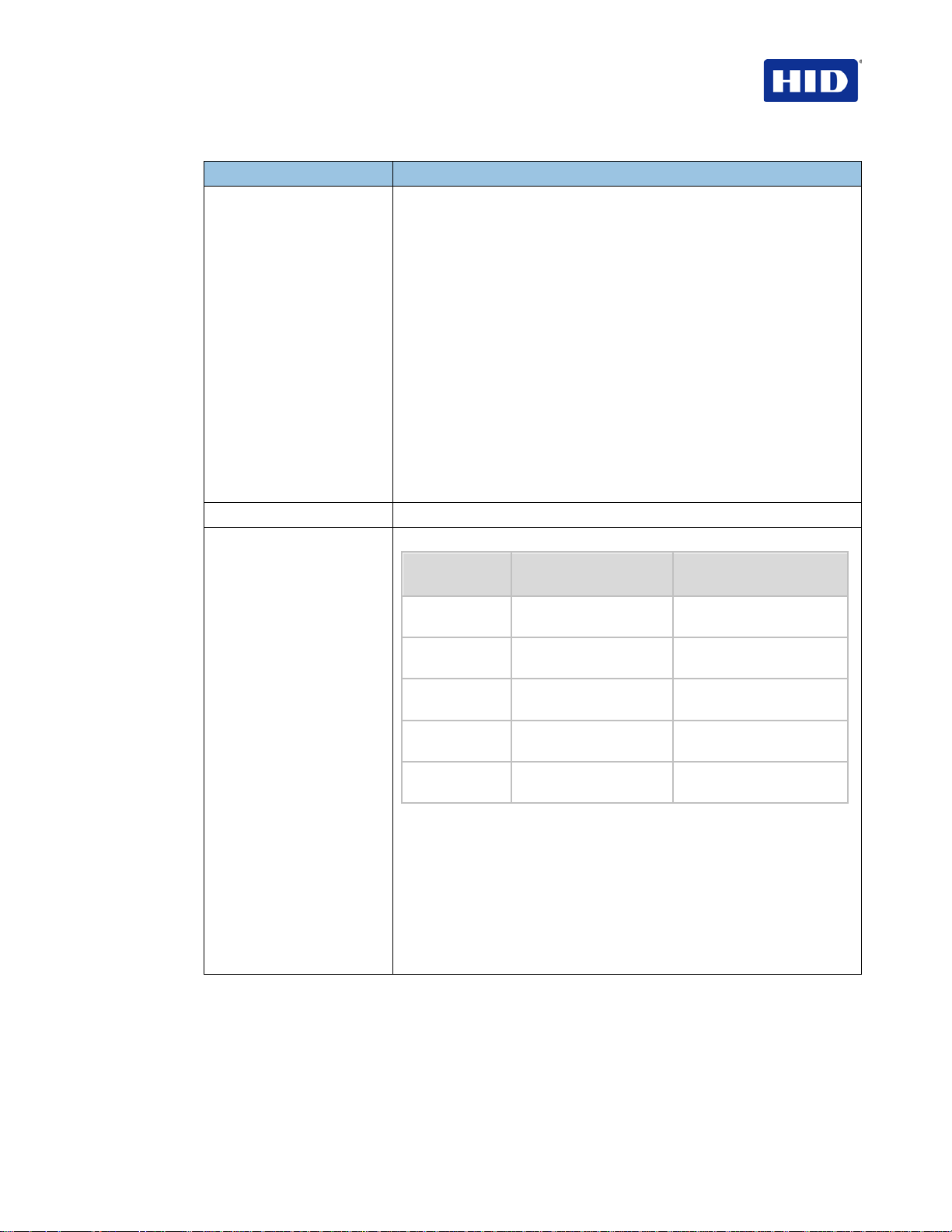
There are two print speed modes: Normal and Performance
Performance Print
Normal Print Mode
YMC 24 seconds per card/
150 cards per hour
YMCK 29 seconds per card/
124 cards per hour
YMCKK 40 seconds per card/
90 cards per hour
YMCK+Lam 34 seconds per card/
106 cards per hour
YMCKK+Lam 48 seconds per card/
75 cards per hour
Performance is most suitable for minimal color and mostly resin text.
• Print speed indicates an approximate print speed and is measured
from the time a card feeds into the Printer to the time it ejects from
the Printer.
• Print speeds do not include encoding time or the time needed for
the PC to process the image.
• Process time is dependent on the size of the file, the CPU, amount
of RAM and the amount of available resources at the time of the
print.
29 seconds per card/ 124
cards per hour
35 seconds per card/ 103
cards per hour
49 seconds per card/ 73
cards per hour
40 seconds per card/ 90
cards per hour
55 seconds per card/ 65
cards per hour
July 2013 Page 11 of 100
© 2012, 2013 HID Global Corporation. All rights reserved.
Page 12

HDP5000 & HDPii Plus Card Printer Encoder User Guide_L000950, 3.0
Supply Frequency
Supply Voltage
Term Description
Software Drivers
Supported
Printers/Models
System Requirements
Warranty
32 bit support for:
• Windows XP
• Server 2003
32 and 64 bit support for:
• Vista
• Server 2008
• Windows 7
• Windows 8
64 bit support for:
• Server 2008 R2
• Server 2012
50 Hz / 60 Hz
120-240 VAC
Ethernet
USB ( 2.0)
x86 based PC or compatible,
• 500MHz computer with 256MB of RAM or higher
• 500MB free hard disk space or higher
Printer: Two year (One year On-Call Express, U.S. only); optional
Extended Warranty Program (U.S. only); see below for more detail.
• Two (2) Year Factory Warranty
• Covers parts and depot repair
• First year On-Call-Express (loaner printer U.S. only )
nd
year On-Call-Express available for a fee. This must be
• 2
purchased before the first year On-Call-Express expires.
• Extended Warranties available
Printhead: Lifetime; unlimited pass with Fargo-certified Cards
3 Setup and Installation Procedures
3.1 Inspection – Card Printer
Page 12 of 100 July 2013
• While unpacking your Printer, inspect the carton to ensure that no damage has occurred
during shipping. Make sure that all supplied accessories are included with your unit.
• Reference the Card Printer Quick Start Guide for information on how to load the Print
Ribbon, Transfer InTM Film, Overlaminates and Card stock.
• See the Quick Start Guide for connecting the Power to the Printer and Lamination
Module.
IMPORTANT:
Do not plug in the USB cable until prompted to do so during the installation of
the Printer Driver. Follow the prompts to install the driver.
© 2012, 2013 HID Global Corporation. All rights reserved
Page 13
HDP5000 & HDPii Plus Card Printer Encoder User Guide_L000950, 3.0
4 Printer Driver Operations
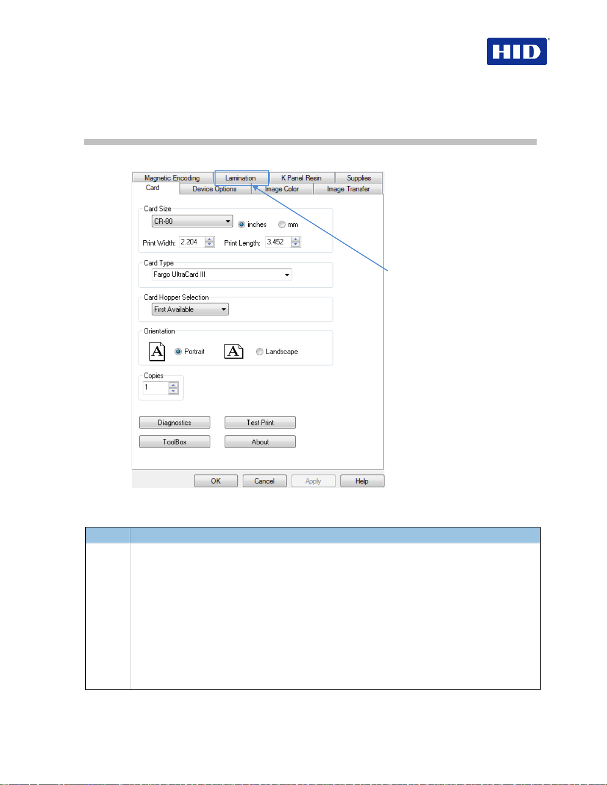
4.1 Using the Card tab
HDP5000 Only
4.1.1 Selecting the Card Size
Step Procedure
1
Select the Card Size option:
• CR-80: This selection is the default form size for the printer. This will print a 2.125 X 3.374
image including a .04 over-bleed on each of the 4 sides making the overall form size 2.204 X
3.452 (56 X 87.7 mm).
• Custom: Use this selection to create a custom form size from 1.0 x 3.0 to 2.204 to 3.452 (25.4
X 76.2 mm to 56 X 87.7 mm).
• The dimensions of the total print area for each card size appears in the Print Width and Print
Length boxes.
• These print area dimensions are .04" (1mm) larger than the actual card size. This is so the
Printer can overprint images ensuring they appear Edge-to-Edge when transferred to the card.
• When designing a card format, set the card or page size within the card design program to the
exact Print Length and Width dimensions listed in the Printer Driver.
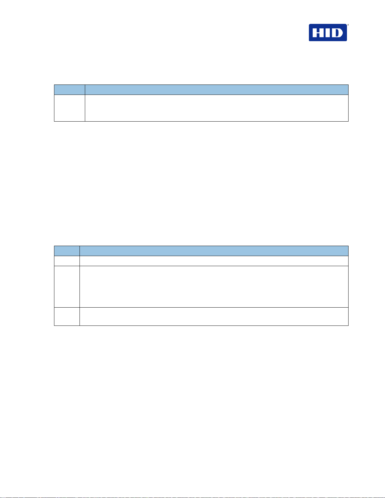
4.1.2 Selecting the Card Type
July 2013 Page 13 of 100
© 2012, 2013 HID Global Corporation. All rights reserved.
Page 14

HDP5000 & HDPii Plus Card Printer Encoder User Guide_L000950, 3.0
: The Printer Driver software has default Transfer Temperature and Dwell Time settings
From the
Card Type
dropdown li st, select the desired
Card Type
according to the
composition of the card stock.
Step Procedure
1 You have these selections (to choose from) Norma l print mo de:
• Fargo UltraCard III (Default Card Type) = 190°C and 2.0 sec.
• Fargo UltraCard Premium = 185˚ and 2.0 sec
• Fargo Ultracard = 175˚and 2.0 sec
• HID Tech Card Composite = 190˚ and 2.0 sec
• HID Tech Card PVC =185˚and 2.0 sec
• Indala FlexISO – Standard (FPISO) = 185˚and 2.0 sec
• Indala FLexISO XT-Composite (FPIXT) 190˚ and 2.0 sec
• Custom 1 = 175˚and 2.0 sec
• Custom 2 = 175˚and 2.0 sec
Defaults
that deliver the best transfer for these card types. These defaults automatically configure based
on the card type, Ribbon type and whether printing single- or dual-sided.
Card Type Selection: Before printing, if using these standard Fargo card types, ensure
selecting the appropriate card type from the Card tab of the Printer Driver.
Proper Settings: Not all card types are accommodated by these default settings. In some
cases, experimentation is required to find the proper settings.
IMPORTANT: If you select the wrong option, the wrong Dwell Time and temperature may be
used during the image transfer process resulting in poor adhesion of the InTM Film or card
warping.
2 If using a card stock other than listed, use the Custom 1 options to save custom Dwell Time and
dwell temperature controls on the Image Transfer
tab.
a. Click Custom options and enter a name for the card stock.
b. Click Image Transfer tab to adjust the Dwell Time and temperature sliders to the
appropriate settings (see next page). Note: These settings will be saved for the custom
card type when the Printer Driver setup window is closed.
c. Custom Card stock:
Tape Adhesion Test. See Section 7.1.2 Conducting the Tape Adhesion Test.
To determine the proper settings for custom card stock, apply the
Page 14 of 100 July 2013
© 2012, 2013 HID Global Corporation. All rights reserved
Page 15
Step
Procedure
HDP5000 & HDPii Plus Card Printer Encoder User Guide_L000950, 3.0
4.1.3 Setting the Orientation
Select either the
Step Procedure
1
Select Portrait to cause the card to print in a vertical orientation.
OR
Select Landscape to cause the card to print in a horizontal orientation.
Portrait
or
Landscape
radio buttons for Orientation.
4.1.4 Card Hopper Selection
Specifies which hopper the printer feeds a card. Selecting
feed from the top hopper. Selecting
Hopper Bottom
Hopper Top
allows the printer to feed from the bottom
hopper. First available feeds a card from the last successful hopper location first, and then
switches to the other hopper.
allows the printer to
4.1.5 Specifying the Number of Copies
Specifies the number of copies to be printed
The upper limit is 10000 and the lower li mit is 1.
4.1.6 Selecting the Diagnostics button
Click
Diagnostics
to launch the WorkBench Printer Utility.
4.1.7 Printing a Test Print Image
Click
Test Print
1 Install a compatible ribbon in the Printer for the Test Print.
2 Open the Driver settings.
a. From your computer’s startup menu, select Settings > Printers and Faxes.
b. Double-click the Printer under the Printer’s window.
c. Select Printing Preferences under the Printer drop-down menu. Note: This brings up the
Printing Preferences window.
3
a. Select the Card tab, and then click Test Print.
b. When selecting the Test Print button, an image is copied to the Printer.
to test the printer.
4.1.8 Selecting About
Select
to open a dialog box containing the Copyright, Driver Version and Date.
About
July 2013 Page 15 of 100
© 2012, 2013 HID Global Corporation. All rights reserved.
Page 16
HDP5000 & HDPii Plus Card Printer Encoder User Guide_L000950, 3.0
Step
Procedure
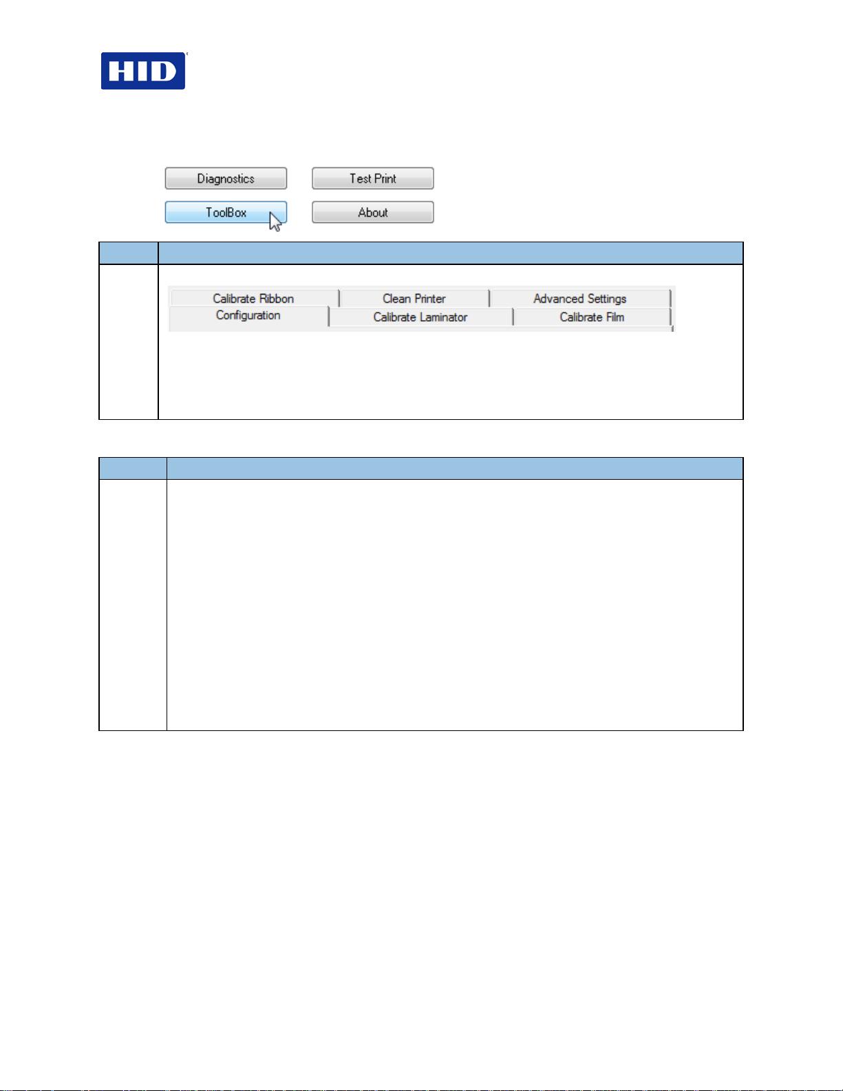
4.1.9 Selecting the Toolbox button
1 Select Toolbox to access the Toolbox window and its tabs, as shown throughout this section.
OK button: Closes the dialog box and saves the Driver configuration changes since the Driver dialog
box has been opened.
Cancel button: Closes the dialog box and cancels the Toolbox changes since the Driver dialog box has
been opened.
Help button: Launches Help specific to the Active tab.
4.2 Selecting the Configuration tab
Step Procedure
1
Select the Configuration tab.
• Under Optional Printer Features, select features by clicking a check box.
The Default setting is checked.
• If checked, upon Configuration tab activation, the Driver retrieves the installed Printer features
information from the Firmware and automatically checks the appropriate check boxes for Dual
Sided, Lamination and Magnetic Encoder.
• If checked, the Dual Sided, Laminator, and Magnetic Encoder checkboxes are read only.
• If checked and no Printer is found or bi-directional capabilitie s are disabl ed or unava ila ble, t he
error message (shown) is displayed.
• If unchecked or cleared, feature check boxes become active and can be manually set.
• If the Driver is reinstalled, it resets to the default of checked.
• Under Event Monitoring, select events to be monitored.
Note: The Driver prompts the User when the selected events occur.
• Under Set Language for Printer LCD Display, select a language.
4.2.1 Using the Event Monitoring Group Box
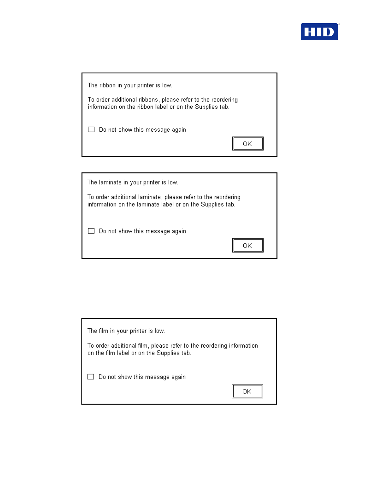
This Event Monitoring group box displays the Low Supplies (Ribbon, Laminate and InTM
Film).
• The default setting is checked. If checked, the Ribbon Low message box is displayed
with every print job when Printer reports low Ribbon to the Driver.
• Do not show this message again. This check box allows the user to suppress a
message per Driver instance. Default = unchecked.
Page 16 of 100 July 2013
© 2012, 2013 HID Global Corporation. All rights reserved
Page 17
HDP5000 & HDPii Plus Card Printer Encoder User Guide_L000950, 3.0
4.2.2 Reviewing the Ribbon Low message
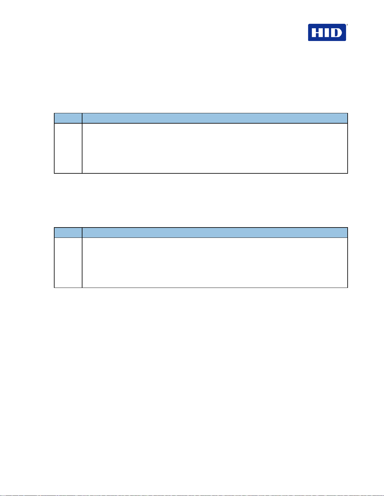
4.2.3 Reviewing the Laminate Low Message
The default setting is checked.
• If checked, Lamination Low message box is displayed with every print job when the
Printer reports low Lamination to the Driver.
• Do not show this message again. This check box allows the user to suppress a
message per Driver instance. Default = unchecked.
4.2.4 Using the InTM Film Low message
The default setting is checked.
• If checked, InTM Film Low message box is displayed with every print job when Printer
reports low InTM film to the Driver.
July 2013 Page 17 of 100
© 2012, 2013 HID Global Corporation. All rights reserved.
Page 18

HDP5000 & HDPii Plus Card Printer Encoder User Guide_L000950, 3.0
Step
Procedure
• Do not show this message again. The check box allows the user to suppress the
message per Driver instance. Default = unchecked.
4.2.5 Using the Clean Printer message
The default setting is checked. If checked, a clean printer message displays after 3000 prints.
4.2.6 Using the Error Status message
The default setting is checked. If checked, error messages (with solutions) display when an
error occurs.
4.2.7 Using the Password Prompt message
The default setting is checked.
• If checked, a dialog message requests a password to continue printing.
• Password protection is set and activated in the Workbench.
4.2.8 Selecting the Display Language
There are two areas where you change interface languages, the workstations Driver software
and the printer display.
Select the Driver software language when installing the driver. For changing the Driver
software language after the initial installation, use the
The default printer language is English. By sending a language pack file to the printer, the
printer is capable of other languages. Change the printer language by using the
(once sending the proper language pack to the printer). Only the languages available within
the printer firmware (as downloaded through the language packs) are choices in the dropdown
menu. Contact Technical Support to obtain printer language packs.
Toolbox
.
Toolbox
4.3 Selecting the Calibrate Laminator tab
The
Calibrate Laminator
manually selected (Printer Feature from the Configuration tab). If the Laminator is not
detected, the tab is active; however, functions are grayed out.
• Calibrate button: Sends calibrate Laminator command to Printer. Follow the
instructions to set up the Printer.
• Help button: Launches help specific to this tab.
1
Select the Calibrate Laminator tab.
a. Ensure that the Cartridges are out of the Laminator.
b. Ensure the Laminator Cover is closed.
c. Click Calibrate.
Note: The Printer’s LCD will display CALIBRATE PASSED. Error Message Calibration Failed may
be solved by manually increasing the sensor calibration number to 13 of higher under the
Advanced Settings tab. Do not use the AUTO calibrate function.
d. Click OK on the LCD display to complete the procedure.
tab is active when the Laminator is detected automatically or
Page 18 of 100 July 2013
© 2012, 2013 HID Global Corporation. All rights reserved
Page 19
Step
Procedure
HDP5000 & HDPii Plus Card Printer Encoder User Guide_L000950, 3.0
4.4 Selecting the Calibrate Film tab
The two buttons for the Calibrate InTM Film tab are described.
• Calibrate button: Sends calibrate film command to Printer. Follow the instructions to
set up the Printer.
• Help button: Launches help specific to this tab.
1
Select the Calibrate Film tab.
a. Ensure that the InTM Film Cartridge is installed.
b. Ensure the Printer’s Cover is closed.
c. Click Calibrate.
Note: The Printer’s LCD will display CALIBRATE PASSED.
d. From the LCD display, click OK to complete the procedure.
4.5 Selecting the Calibrate Ribbon tab
The two buttons for the Calibrate Ribbon tab are described below.
• Calibrate button: Sends the Calibrate Ribbon Command to the Printer. Follow the
instructions to set up the Printer.
• Help button: Launches help specific to this tab.
Step Procedure
1 Select the Calibrate Ribbon tab.
a. Ensure that the Ribbon Cartridge is removed.
b. Ensure the Printer’s Cover is closed.
c. Click Calibrate.
Note: The Printer’s LCD will display CALIBRATE PASSED.
d. Click OK on the LCD display to complete the procedure.
July 2013 Page 19 of 100
© 2012, 2013 HID Global Corporation. All rights reserved.
Page 20
HDP5000 & HDPii Plus Card Printer Encoder User Guide_L000950, 3.0
Step
Procedure
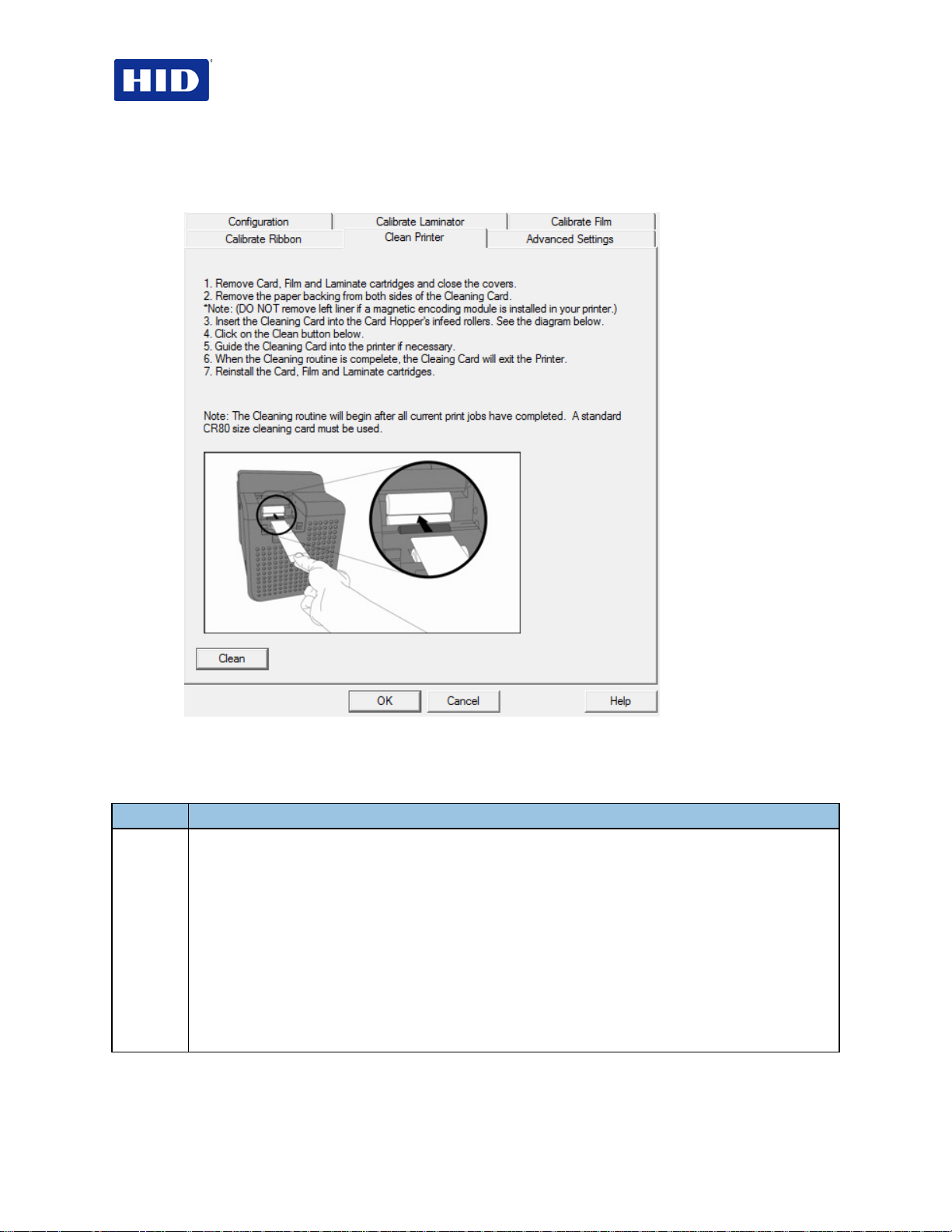
4.6 Selecting the Clean Printer tab
To clean the printer, follow the instructions outlined on the
Clean Printer
tab.
Figure 1 - Clean Printer
• Clean button: Launches cleaning routine. Follow the instructions to set up the Printer.
• Help button: Launches help specific to the Clean Printer tab.
1
Click the Clean Printer tab.
a. Remove the Card, InTM Film and Laminate Cartridges and close the covers.
b. Remove the paper back from both sides of the Cleaning Card.
Note: DO NOT remove the left liner if a Magnetic Encoding Module is installed in your printer.
c. Insert the Cleaning Card into the Card Hopper’s infeed rollers.
d. Click Clean button.
e. Guide the Cleaning Card into the Printer as needed.
f. When the Cleaning routine is complete, the Cleaning Card exits the Printer.
g. Reinstall the Card, InTM Film and Laminate Cartridges.
The Cleaning routine begins after completing all current print jobs. Use a standard CR80 sized
cleaning card.
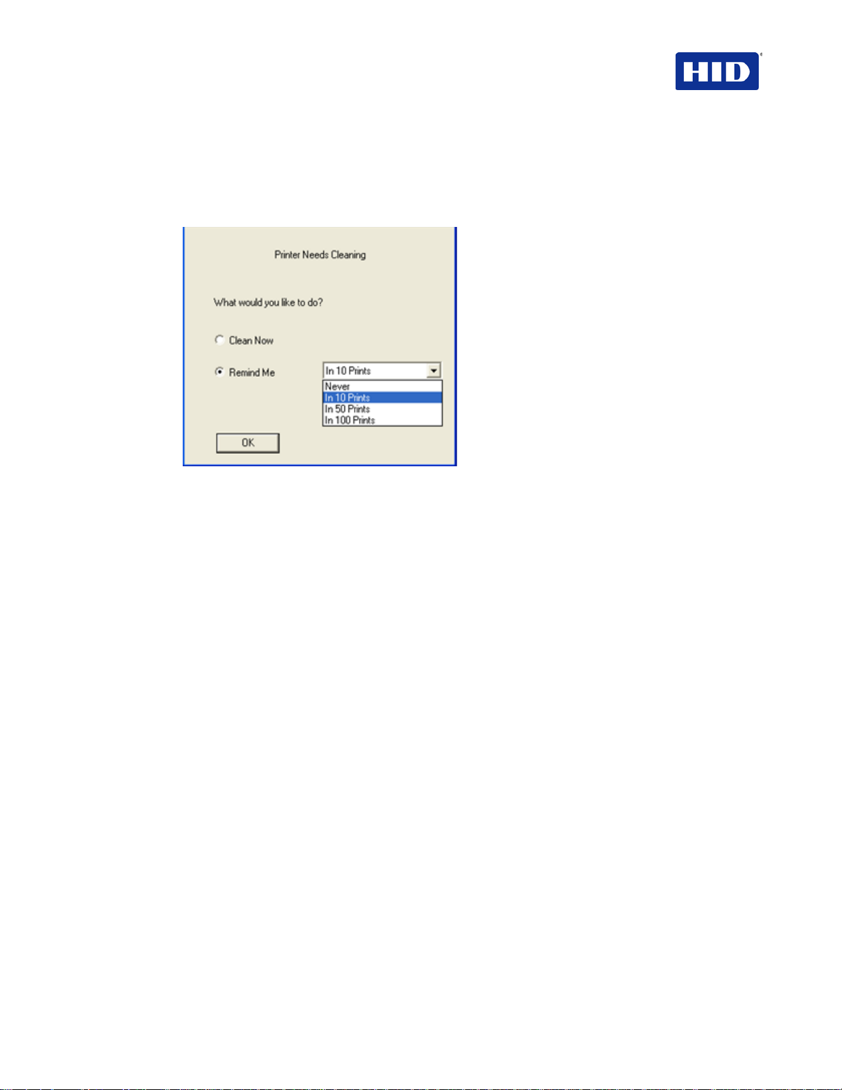
4.6.1 Using Clean Printer Group
Page 20 of 100 July 2013
© 2012, 2013 HID Global Corporation. All rights reserved
Page 21
HDP5000 & HDPii Plus Card Printer Encoder User Guide_L000950, 3.0
The Clean Printer Group dialog is a Status Message initiated by the
Monitoring
You can decide to click
Cleaning Notification
Note:
(see
Configuration
Remind Me
dialog displays when Firmware EE setting changes after 3000 cards.
The Firmware EE setting resets upon sending the clean command to the Firmware.
dialog). When displayed, selected is
and set the reminder as desired. If checked, the
Printer Event
Clean Now
(default).
Printer
• Clean Now radio button: This is the default. When you click OK, launched is the
Toolbox to the Clean Printer tab.
• Remind Me radio button : This activates a drop down for the User to choose a number
of cards to print until the next reminder. If the User chooses Never, then the Clean
Printer notification is cleared from Configuration tab.
• OK button: Clicking OK accepts the settings and closes the dialog.
• Cancel button: Clicking Cancel, closes the dialog without saving changes. If the User
exits the Toolbox without clicking Clean, the Printer Cleaning Reminder dialog box
reappears on the next print.
4.6.2 Cleaning the Rollers
For additional cleaning information, see the Cleaning Kit Instructions provided with the
Cleaning kit.
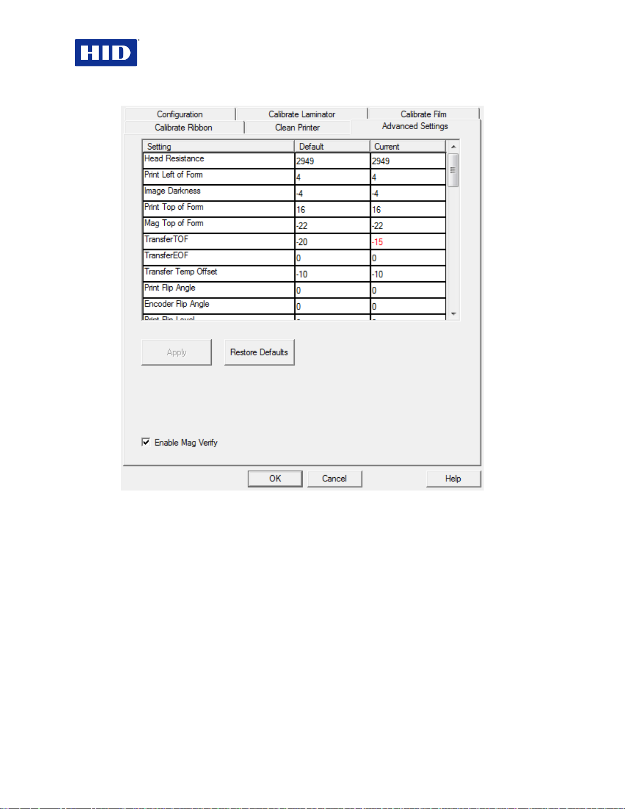
4.7 Selecting the Advanced Settings tab
Use the
Advanced Settings
settings for each printer and save the settings within the Printer memory.
Select
Note:
Restore Defaults
CAUTION: In general, do not adjust these settings after the original printer
configuration from the factory. However, under rare circumstances it is necessary to
adjust these settings in the field. Ensure you have advanced knowledge prior to
making these adjustments.
The described Settings change values for the Firmware. The following sections describe each
setting and their use.
July 2013 Page 21 of 100
© 2012, 2013 HID Global Corporation. All rights reserved.
tab for adjusting the internal printer settings. Customize the
to restore the internal default settings.
Page 22
HDP5000 & HDPii Plus Card Printer Encoder User Guide_L000950, 3.0
Figure 2 - Advanced Settings
• Setting column: Displays the type of setting
• Default column: Displays the default setting value
• Current column: Displays the current setting value
Change the Current value by clicking the field to activate the control and enter the new
value.
• Apply button: Applie s chang ed val ue s.
• Restore Defaults button: Restores default values.
4.7.1 Head Resistance
This value is factory set. If the main circuit board or the printhead is replaced, adjust this
number.
• Locate the Printhead Setting Number on the bottom of the Printhead.
• The number reads R=XXXX.
Page 22 of 100 July 2013
© 2012, 2013 HID Global Corporation. All rights reserved
Page 23
HDP5000 & HDPii Plus Card Printer Encoder User Guide_L000950, 3.0
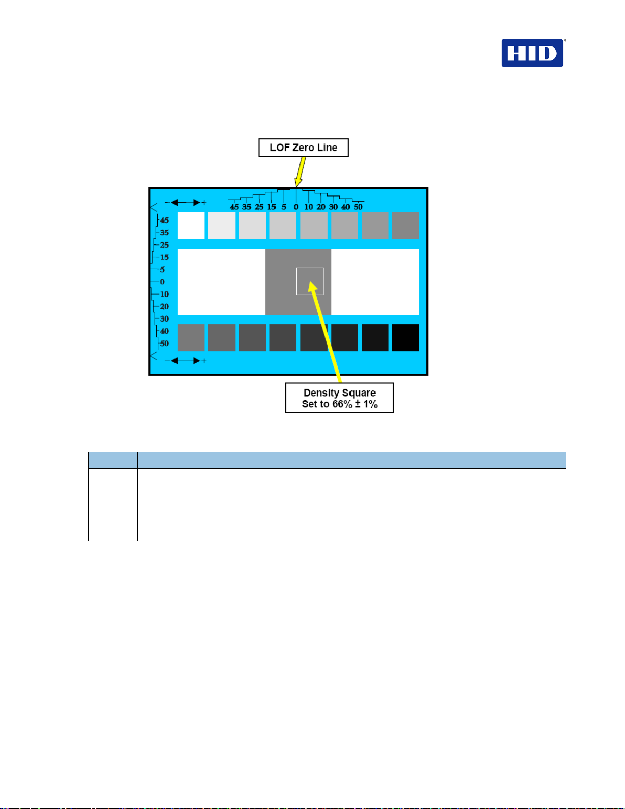
4.7.2 Print Left of Form
From
Advanced Settings
, modify the
Print Left of Form
Setting.
Figure 3 - Print Left of Form
Step Procedure
1 Print the Alignment Card Self-test.
2 Adjust the Print LOF up or down until the border of the LOF Zero Line is showing on the edge of the
card as shown.
3 Measure the density square, as shown.
Adjust the image density to 66% ± 1%.
July 2013 Page 23 of 100
© 2012, 2013 HID Global Corporation. All rights reserved.
Page 24

HDP5000 & HDPii Plus Card Printer Encoder User Guide_L000950, 3.0
4.7.3 Image Darkness
Use the Image Darkness Setting to adjust the overall darkness of the printed image by
increasing or decreasing the amount of heat used by the Printhead when printing.
Step Procedure
1
Lighten the printed image by clicking or enter the exact negative value decreasing the Printhead
heat.
Darken the image by clicking or entering a positive value increasing the amount of Printhead heat.
IMPORTANT: If the Image Darkness Setting is set too high, the Ribbon may jam or break.
Figure 4 - Image Darkness
Page 24 of 100 July 2013
© 2012, 2013 HID Global Corporation. All rights reserved
Page 25
HDP5000 & HDPii Plus Card Printer Encoder User Guide_L000950, 3.0
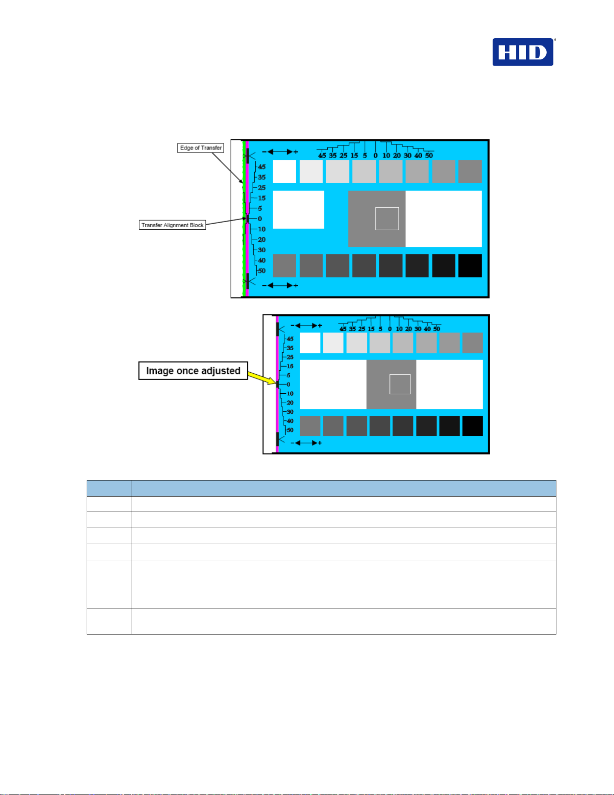
4.7.4 Print Top of Form
From
Advanced Settings
, modify the
Print Top of Form
Setting.
Figure 5 - Print Top of Form
Step Procedure
1 Verify the Transfer TOF is set to +35.
2 Verify the Print TOF is set to +20.
3 Verify the Print LOF is set to +7.
4 Print the alignment card self-test (the front edge should look like the figure).
5 Adjust the Print TOF until the green border is eliminated and the entire Transfer Alignment Block is
shown in the center of the card.
Note: Due to variation in roller alignment, the green border may appear at a slight angle on the top of
the card.
6 Verify the entire alignment block is visible and the green has been eliminated from the center of the
card.
July 2013 Page 25 of 100
© 2012, 2013 HID Global Corporation. All rights reserved.
Page 26
HDP5000 & HDPii Plus Card Printer Encoder User Guide_L000950, 3.0
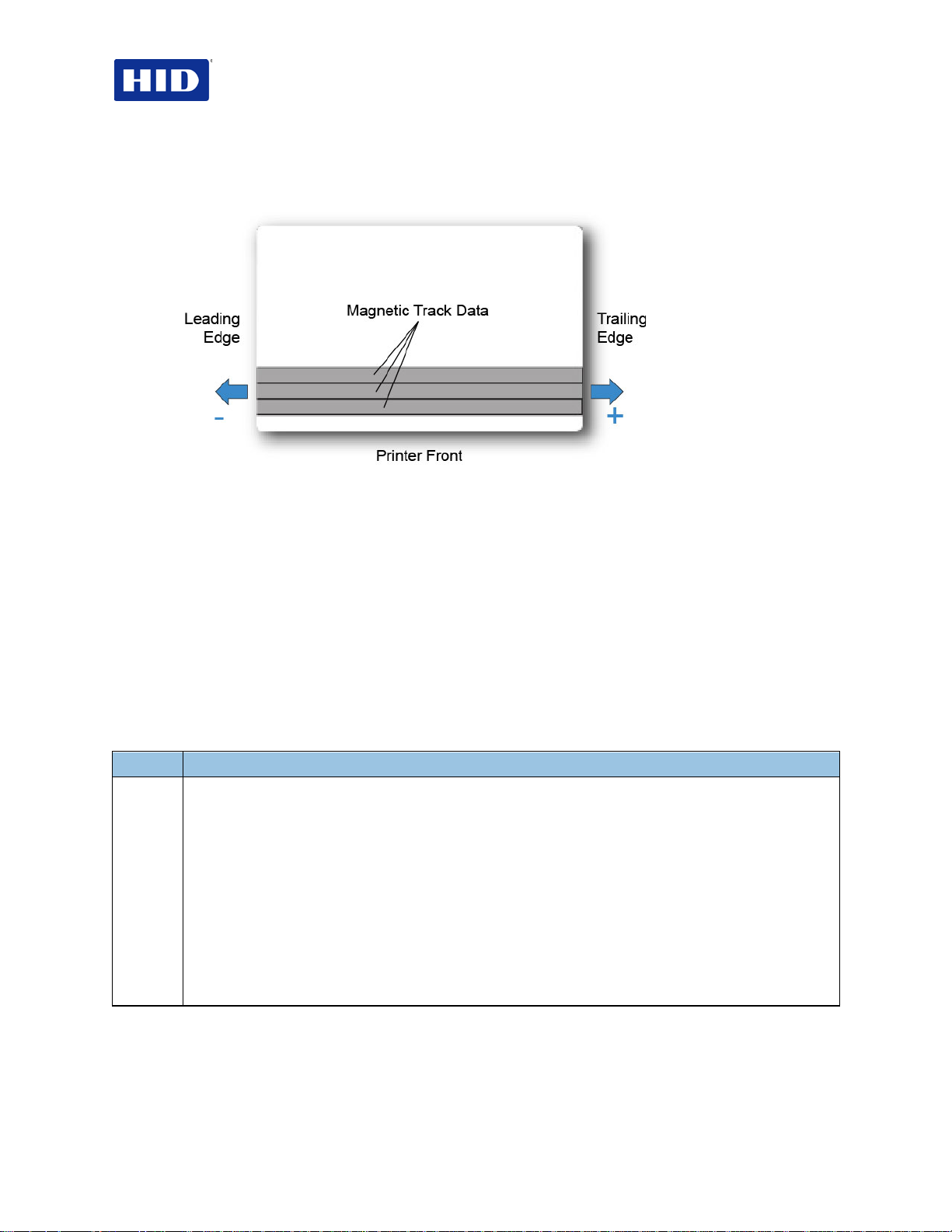
4.7.5 Mag Top of Form Setting
From
Advanced Settings
Figure 6 - Mag Top of Form
The Magnetic Stripe is on the front of the card (front of printer).
Use this option only if the Printer has a built-in Magnetic Stripe Encoder.
• If so, this option shifts the starting point of where the Printer begins encoding the
magnetic track data on a card's Magnetic Stripe.
• When adjusting this value, keep in mind that a card and its Magnetic Stripe always
remains in the same relative position as the card travels through the Printer.
The diagram represents:
• How the magnetic data will move in relation to the fixed position of a card's Magnetic
Stripe as a “positive” or “negative” Magnetic Offset value is entered.
• For this diagram, assume that the card is transparent and the card's Magnetic stripe can
be seen through the top or front side of the card.
, modify the
Mag Top of Form
Setting.
Step Procedure
1 Enter a negative value to move the start of the magnetic data more toward the leading edge of the card
or the card output side of the Printer.
OR
Enter a positive value to move the start of the magnetic data toward the trailing edge of the card or the
card input side of the Printer.
• Magnetic Data Direction: The arrows on these buttons indicate the direction the magnetic data
will move on the card's Magnetic Stripe.
• Maximum Adjustment Range: The maximum adjustment range is ± 99. As a rule, 20 equals
about .030"/. 8mm.)
Note: Keep this in mind when adjusting this option to avoid over-adjusting.
IMPORTANT: If the negative value is set too high, the Printer may start encoding before the card's
Magnetic Stripe reaches the encoding hea d.
Page 26 of 100 July 2013
© 2012, 2013 HID Global Corporation. All rights reserved
Page 27
Step
Procedure
Step
Procedure
HDP5000 & HDPii Plus Card Printer Encoder User Guide_L000950, 3.0
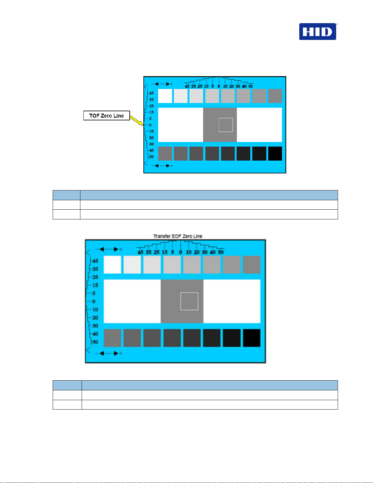
4.7.6 Transfer Top Of Form
Figure 7 - Transfer Top of Form
1 Print the alignment card self-test.
2 Adjust the Transfer Top of Form value until the TOF Zero Line is located on the card edge as shown.
4.7.7 Transfer End of Form
Figure 8 - Transfer End of Form
1 Print the alignment card self-test.
2 Adjust the Transfer End of Form value until the EOF Zero Line is located on the card edge as shown.
July 2013 Page 27 of 100
© 2012, 2013 HID Global Corporation. All rights reserved.
Page 28
HDP5000 & HDPii Plus Card Printer Encoder User Guide_L000950, 3.0
4.7.8 Transfer Temp Offset
This option adds an offset to the printer temperature of the transfer roller.
Use this setting only for making the temperature of the transfer roller and the LCD goal
Note:
match.
• Use the Image Transfer tab slider to make adjustments for card stock.
• A negative (-) adjustment increases the actual roller temperature.
4.7.9 Print Flip Angle
Use the
after a flip operation.
Print Flip Angle
option to set the position of the flipper so it is level with the card path
4.7.10 Encoder Flip Angle
Use the
Note:
this option .
Encoder Flip Angle
This setting is in relation to the printer's built-in encoder if your printer is equipped with
option to fine-tune the position of the flipper.
4.7.11 Print Flip Level
Use the
Print Flip Level
option to set the position of the flipper so it is level with the card path.
4.7.12 Ribbon Print Takeup Tension
Use the
Adjust the Ribbon tension if the Ribbon wrinkle is appearing on the card.
Note:
Ribbon Print Takeup Tension
Adjustments moderately change the image length.
to set the tension of the color Ribbon during printing.
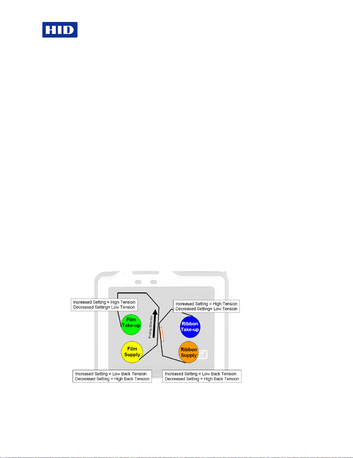
4.7.13 Using the Ribbon Print Supply Tension Setting
This procedure controls the tension of the color Ribbon during printing. Adjust the Ribbon
tension if the Ribbon wrinkle is appearing on the card.
Adjustments moderately change the image length. “+” Adjustments can eliminate some
Note:
cases of wrinkle
Figure 9 - Ribbon Print Supply Tension
.
Page 28 of 100 July 2013
© 2012, 2013 HID Global Corporation. All rights reserved
Page 29
HDP5000 & HDPii Plus Card Printer Encoder User Guide_L000950, 3.0
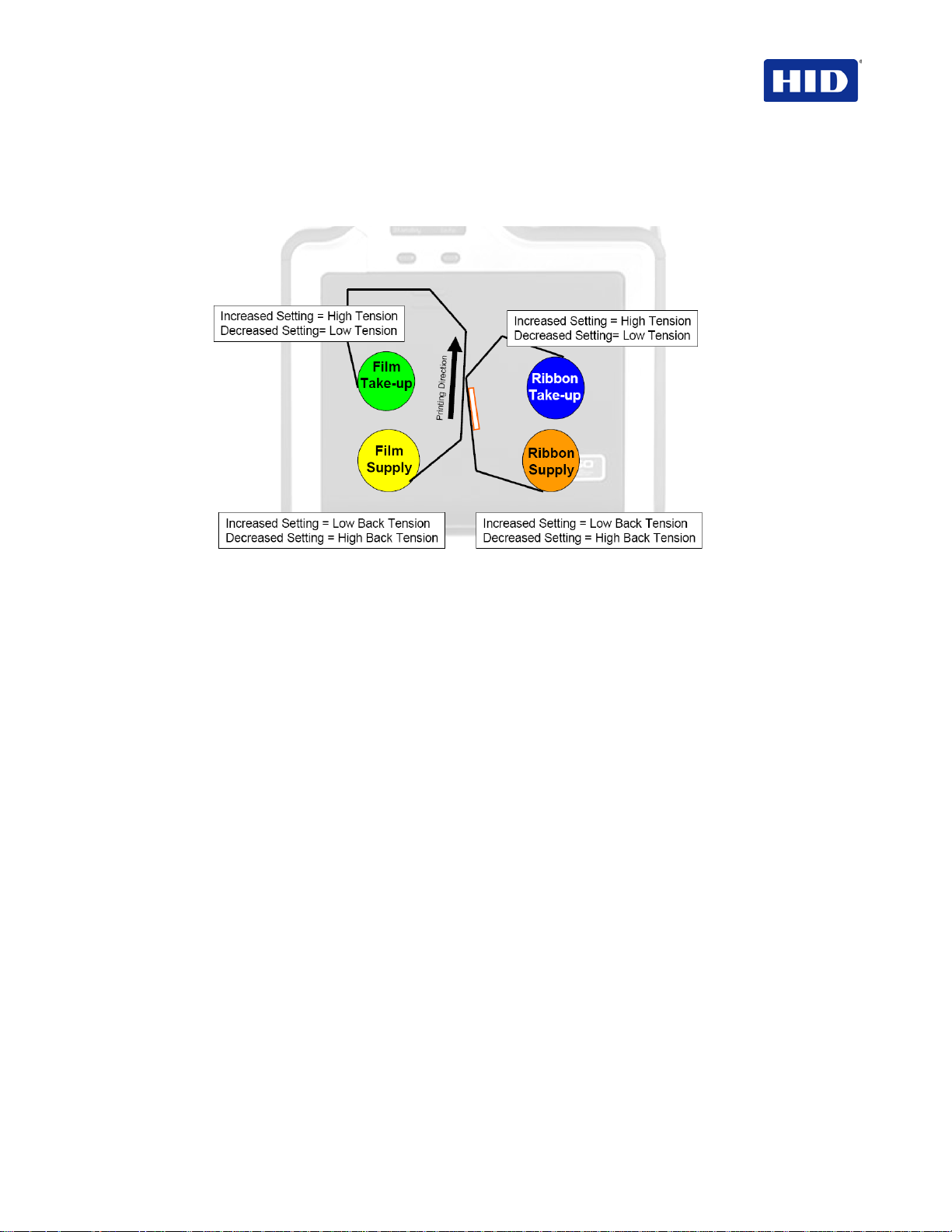
4.7.14 Film Print Takeup Tension
Use the Print Takeup Tension to set the baseline for the film tension.
Do not adjust the InTM Film Drive.
Note:
Figure 10 - Film Print Takeup Tension
4.7.15 Resin Heat Adjust
Use this adjustment for when the Black resin text and barcodes appear faded or too light/dark.
4.7.16 Sleep Time
This setting adjusts the time until the printer stops energizing the transfer roller conserving
energy. Disable is indicated with a 0 setting.
The counter for this setting starts after
Note:
Standby Time
has elapsed.
4.7.17 Blush Point
The blush point is compensation during printing:
• There is no dye transfer.
• There is no a light gray line on a portion of the card.
• It should be white.
4.7.18 LCD Contrast
This setting adjusts the LCD panel brightness.
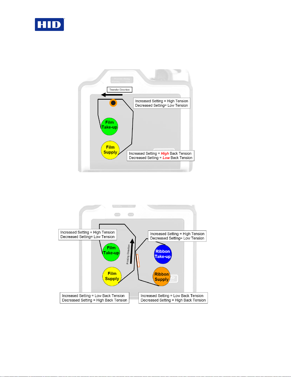
4.7.19 Using the Film Supply Transfer Tension Setting
Adjustments significantly change image length. Recommend only small adjustments due to
sensitivity.
Adjustments affect flash and smudge.
Note:
July 2013 Page 29 of 100
© 2012, 2013 HID Global Corporation. All rights reserved.
Page 30
HDP5000 & HDPii Plus Card Printer Encoder User Guide_L000950, 3.0
4.7.20 Film Takeup Transfer Tension
Negative (-) adjustments may cause card jams.
While positive settings help stop jamming. Adjustments affect flash and smudge.
Note:
Figure 11 - Film Takeup Transfer Tension
4.7.21 Film Print Supply Tension
This setting establishes the baseline for the film tension. Do not adjust. Changes to this value
moderately change the image length.
Figure 12 - Film Print Supply Tension
Page 30 of 100 July 2013
© 2012, 2013 HID Global Corporation. All rights reserved
Page 31

HDP5000 & HDPii Plus Card Printer Encoder User Guide_L000950, 3.0
4.7.22 Film Print Cooling Level
This setting controls the speed of the transfer roller-cooling fan during the printing process.
This setting should be
on the image. Too high of a fan speed can cause smudge.
. Turn on the InTM Print Cooling to help with splotchy color areas
OFF
4.7.23 Film Transfer Cooling Level
This setting controls the default speed of the cooling fan for the transfer process.
In addition, the Film Transfer Cooling Level adjusts fan speeds and when they are on during
transfer. This setting affects both flash and smudge.
4.7.24 EAT Disable
This setting is an ON or
process of tracking the environmental temperature and to compensate for fluctuation.
Environmentally Adaptive Transfer (EAT) automatically adjusts the transfer temperature based
on the ambient air conditions within the printer. EAT increases or decreases the transfer roller
temperature by as much as 20C in extreme conditions.
The
EAT Disable
Setting defaults to ON.
switch, where 0 is off and 1 is ON. This setting is part of the
OFF
4.7.25 Enable Ribbon Wrinkle Comp
This setting is an ON or
extra pixels on the printhead to help mitigate ribbon wrinkle during the print process.
switch. Using Enable Ribbon Wrinkle Compensation turns on
OFF
4.7.26 Standby Time
This setting adjusts the time until the printer goes into a reduced transfer roller temperature to
conserve energy.
A zero (0) setting disables. Settings are in minutes.
4.7.27 Beep Disable
This setting turns off the beeping sound, suppressing audible event notification.
4.7.28 I-Panel Heat Offset
This option adjusts the heat used during the removal of unwanted InTM Film. Use minimal
adjustments. Otherwise, print ribbon and film breaks may occur.
4.7.29 Holo Transfer Offset
This option changes the Hologram Overlaminate Offset for placement parameters.
4.7.30 Standby Temperature
This option changes the temperature used when the printer is in standby mode.
4.7.31 Mag Hi-Co Voltage Offset
This changes the voltage going to the magnetic head.
Mag Hi-Co Voltage Offset is factory set. Do not change without a technician.
4.7.32 Mag Lo-Co Voltage Offset
This option changes the voltage going the magnetic head.
Mag Lo-Co Voltage Offset is factory set. Do not chang e w it ho ut a te c hnician.
July 2013 Page 31 of 100
© 2012, 2013 HID Global Corporation. All rights reserved.
Page 32

HDP5000 & HDPii Plus Card Printer Encoder User Guide_L000950, 3.0
4.7.33 Mag Flipper Angle Offset
This option changes the angle of the Flipper Table. Increasing the flipper angle rotates the
flipper table clockwise. The Mag Flipper Angle Offset is factory setting. Do not change without
a technician.
4.7.34 Fluorescent Heat Offset
Use this setting to adjust how dark or light the fluorescent (F) panel is printed. The value has a
range of +/-20.
4.7.35 Warming Delay Time
Use this setting to adjust how much additional time (in minutes) the printer waits after the
transfer roller reaches temperature before beginning transfer. The value has a range of 0 to
20.
4.7.36 Enable Ribbon and Film Saving
This setting enables power up ribbon/film savings. When enabled the ribbon and film
will not skip to a new set of panels after a power up. Cover open/close behavior is
unaffected, so upon a cover close the ribbon and film will skip a set of panels.
0 – disabled/1- enabled.
4.7.37 Transfer Image Length
Use this setting to adjust the length of the image on the card during transfer. The value has a
range of -10 to +10. An increase in the number increases the length of the image.
4.7.38 Transfer Cooling Delay
Use this setting to adjust the delay (in seconds) before transferring the second side of the
card. The value has a range of 0 to 180. An increase in the number increases the length of the
delay in seconds.
4.7.39 Hologram Film Transfer Release Tension
Use this setting to adjust the back tension of the film during the release phase when
holographi c film is used. An increasingly negative value increases the back tension. Higher
back tension can fix trailing edge flash.
4.7.40 Enable Alternate Transfer Release
Use this setting to enable/disable the alternative transfer release routine. When enabled, this
routine can improve smudging on cold printers.
4.7.41 Proximity Encoder Card Offset
Use this setting to fine tune the card position when docking a card into the prox encoder in
Bay 2. The setting adjusts the number of steps out from a fully docked position that the card is
placed.
Page 32 of 100 July 2013
© 2012, 2013 HID Global Corporation. All rights reserved
Page 33

HDP5000 & HDPii Plus Card Printer Encoder User Guide_L000950, 3.0
4.7.42 Reviewing the No Printer Connected Error Message
If the driver is unable to communicate with the printer, the following error displays and the grid
is blank.
Figure 13 - Unable to Read Settings Message
4.7.43 Reviewing the Value Outside the Range Error Message
If typing a value outside the range, an error message displays specific to the setting when
leaving the con t rol.
Figure 14 - Value Outside Range Message
July 2013 Page 33 of 100
© 2012, 2013 HID Global Corporation. All rights reserved.
Page 34

HDP5000 & HDPii Plus Card Printer Encoder User Guide_L000950, 3.0
4.8 Using the Device Options tab
Figure 15 - Device Options
Page 34 of 100 July 2013
© 2012, 2013 HID Global Corporation. All rights reserved
Page 35

Step
Procedure
HDP5000 & HDPii Plus Card Printer Encoder User Guide_L000950, 3.0
4.8.1 Detecting Supplies at Print Time Function
1
2
3
Use the Supplies checkbox for auto detection of the consumables, which are the Ribbon and InTM
Film.
• In the Firmware, the values (representing the installed Ribbon, Transfer InTM Film and Laminate)
are updated on initialization (including each time the cover is closed).
• The Firmware compares the Ribbon and InTM Film values in the PRN file to the values (it holds
regarding the currently installed consumables).
If the values do not match, the LCD displays the Wrong Ribbon and/or Wrong Film error, and the
Driver returns the corresponding error message.
When the Supplies checkbox is checked, the following takes place.
• Ribbon and InTM Film Type dropdown boxes are inactive and populated with values of installed
supplies. Dual Sided and Options are set to defaults for detected supplies.
• For example, no Dual Side options are available without the Flipper installed. This function
provides automatic detection of an installed feature whether it is automatically detecting supplies
or not.
• Before the Driver initiates each job, it retrieves the consumable values from the Firmware.
• If finding no Printer or Ribbon, the Supplies checkbox is enabled the previously chosen Ribbon
and InTM Film values remain. You will see an error message.
• Activating the Device Options tab automatically repopulates the Ribbon and InTM Film types.
Note: You see an error message if no Printer is found when activating the Device Options tab.
When the Supplies checkbox is not checked or it is de-selected (cleared) from a selected state, the
Ribbon and InTM Film dropdown boxes become active and auto selected Ribbon and InTM Film types
remain (until manually changed).
July 2013 Page 35 of 100
© 2012, 2013 HID Global Corporation. All rights reserved.
Page 36

HDP5000 & HDPii Plus Card Printer Encoder User Guide_L000950, 3.0
YMCFK (Full Color/Resin Black/Fluorescing): Yellow, Magenta, Cyan, UV Fluorescing, and Resin
Step
Procedure
4.8.2 Adjusting the Ribbon Type
Use the
Ribbon Type
Step Procedure
1 Adjust to match the Ribbon Type selection with the Ribbon type that is loaded in the Printer.
• YMC (Full Color): Yellow, Magenta, Cyan
OR
• YMCK (Full Color/Resin Black): Yellow, Magenta, Cyan, Resin Black
OR
• YMCKK (Full Color/2 Resin Black): Yellow, Magenta, Cyan, Resin Black, Resin Black
OR
• YMCKH (Full Color/Resin Black/Heat Seal): Yellow, Magenta, Cyan, Resin Black, and Heat Seal
OR
•
Black
• YMCKI (Full Color/Resin Black/Inhibit): Yellow, Magenta, Cyan, Resin Black, Inhibit
• YMCIKH, (Full Color/ Inhibit/Resin Black/Heat Seal): Yellow, Magenta, Cyan, Resin Black, Heat
Seal, Inhibit
• YMCKIKI, (Full Color/Resin Black/ Inhibit/ Resin Black/ Inhibit)
• YMCK Half panel
• YMCKK Half Panel
• K Premium Resin
dropdown menu to match Ribbon type.
4.8.3 Adjusting the (InTM) Film Type
1 Allows you to select the InTM Film type option that is appropriate for the type of InTM Film currently
loaded in the Printer.
• Select the Clear option to automatically adjust the appropriate transfer time and temperature to
pre-determined defaults.
Note: Select this option to automatically adjust the transfer temperature and the dwell times to
defaults when non-custom card type is chosen on Card tab.
OR
• Select the Holographic option to change appropriate internal Printer settings needed to make the
holographic InTM Film work. (Note: Select this option to automatically adjust the transfer
temperature and the dwell times to defaults when non-custom card type is chosen on Card tab.)
• High Durable Clear InTM film
Note: It will also adjust the necessary transfer temperature and the dwell settings in the Driver to
provide the optimal high durable clear InTM Film performance.
Page 36 of 100 July 2013
© 2012, 2013 HID Global Corporation. All rights reserved
Page 37

Step
Procedure
If using an YMCKK Ribbon, the front of the card is printed with the
HDP5000 & HDPii Plus Card Printer Encoder User Guide_L000950, 3.0
4.9 Using the Dual Sided Group Functions
The Dual Sided group checkboxes are disabled if no Flipper is automatically found or if Dual
Sided is manually turned off.
4.9.1 Using the Dual Sided - Print Both Sides option
Use Dual Sided to print automatically onto both card sides.
1
2
Select Print Both Sides radi o button in addition to any program
supporting duplex printing.
Note: The program must send down two or more separate
pages for printing within the same document.
Page 1 is transferred to the front side of the card.
Page 2 is transferred to the backs ide of the card.
With this option selected, the Printer Driver places all odd numbered pages on the front side of the
card and all even numbered pages on the backside.
4.9.2 Using the Print Both Sides - Split 1 Set of Ribbon Panels option
Use this option to provide the most economical means of printing a dual-sided card since a
single set of Ribbon Panels will split to print both the front and backside of a card.
• This option is active when Print Both Sides is checked.
• The Default is active and unchecked except for YMCKK and YMCKIKI, which are
checked.
Step Procedure
1 Select this option to automatically print full-color on the front of a
card and resin black on the back of a card (using YMCKK Print
Ribbons).
YMCK Panels and the back is printed with the second K Panel.
Notes:
This is enabled automatically w hen selecting the YMCKK Ribbon.
This option is not available if using the YMCKH Ribbon.
July 2013 Page 37 of 100
© 2012, 2013 HID Global Corporation. All rights reserved.
Page 38

HDP5000 & HDPii Plus Card Printer Encoder User Guide_L000950, 3.0
Step
Procedure
4.9.3 Using Print Both Sides - Print Back Image on Front of Card
This option becomes active when
unchecked.
1 Select this option:
• If needing to print the first page of a two-page document
on the backside of the card.
OR
• If needing to print the resin black on the chip-sid e of the
Smartcard.
The second page of the document is printed on the front side of
the card.
Print Both Sides
is checked. The Default is active and
4.9.4 Using the Dual Sided - Print Back Side Only option
Use this option to print only onto the backside of cards.
The
Note:
Print Back Side Only
Step Procedure
1
Select Print Back Side Only to print only onto the backside of
preprinted cards that must have their Magnetic Stripe or smart
card chip encoded.
Note: Load the cards in the usual fashion.
• When selecting this option, the Print Both Sides option is
automatically disabled.
• When attempting to print a two-page doc ume nt (i f Print
Back Side Only is selected), the first page of the
document prints on the backside of the card.
• The second page of the document is then pri nted on the
back of a second card.
checkbox default is active and unchecked.
4.9.5 Using the Options Group
Figure 16 - Options
Page 38 of 100 July 2013
© 2012, 2013 HID Global Corporation. All rights reserved
Page 39

Step
Procedure
HDP5000 & HDPii Plus Card Printer Encoder User Guide_L000950, 3.0
4.9.5.1 Using the Rotate 180 Degrees (Front or Back)
Use this option to change the position of the printed image in relation to the set location of a
card's Magnetic Stripe or smart chip.
1
Select the Rotate Front 180 Degrees option to rotate the image on the front of the card by 180
degrees when printed.
OR
Select the Rotate Back 180 Degrees option to rotate the image on the back of the card by 180
degrees when printed.
4.9.5.2 Using the Disable printing option
Use this option to disable the printing capabilities of the Printer while still allowing the Printer to
encode cards.
This option is useful to encode or re-encode preprinted cards without wasting additional
Note:
time or printing supplies.
Step Procedure
1 Select this option to ensure sending no print data to the Printer (while sending all encoding instruct ion s
according to how they are configured within the software).
This option also allows you to laminate the card.
4.9.5.3 Using the Dual Pass and Invert F-Panel Image options
See Configuring Fluorescent Data using Workbench procedure, page 84.
• Dual Pass option: This refers to the fact that the fluorescing dye can be applied to a
separate panel of HDP InTM Film.
Note: First, the YMC ink is applied to a panel of InTM Film; then, the F and possibly K
are applied to a separate panel. If this is not done, the fluorescent ink tends to mix with
the YMC colors and lose its fluorescent qualities; it also tends to become invisible.
Use the default
dye is used or if selecting
Dual Pass option if using the fluorescent image in places where other
Invert F Panel.
• Invert F-Panel option: This refers to the ability to cause light or white areas of the
image to fluoresce and dark colors to remain dark on the printed card when exposed to
a UV light.
Note: This was requested because the fluorescent dye color is bright when black light
is applied to it. By default, the dark areas of the image will fluoresce on the card and the
lighter or white areas will have no dye applied.
The User can select the Invert F-Panel option to cause the black in the design to show
as dark on the card. This option is recommended if the user is printing a photo.
July 2013 Page 39 of 100
© 2012, 2013 HID Global Corporation. All rights reserved.
Page 40

HDP5000 & HDPii Plus Card Printer Encoder User Guide_L000950, 3.0
4.9.6 Using the Resin Scramble Option
Resin Scramble eliminates the personal data traceability on used ribbon panels and lowers
the risk of identity theft.
The Yellow, Magenta, Cyan and resin (K) panels are printed like normal. However, prior to
transfer, the film is reversed to the previously used film panel and the ribbon is rewound to the
beginning of resin (K) panel.
A white noise image is then printed on the resin (K) panel to the used film panel. The film and
ribbon are then backed up again. The white noise image is the printed again but it begins at a
different point of the film from the first pass.
The result is the ribbon has almost no resin left on it while the film has the scrambled image.
Only ribbons with the K panel have this option available in the driver.
4.9.7 Using the Encrypt Job Data
AES256 encryption protects the data passed from the computer to the printer.
HDPii and HDPii Plus printers have Encrypt Job Data enabled automatically.
Note:
Page 40 of 100 July 2013
© 2012, 2013 HID Global Corporation. All rights reserved
Page 41

HDP5000 & HDPii Plus Card Printer Encoder User Guide_L000950, 3.0
4.9.8 Using the Use Substitute Panel Data
Only ribbons with the F or I panel have this option available in the driver.
When selecting
Split Mode
the document is printed to the front of the card with the YMC ribbon panel. Following, the
second page is printed on the front of the card with the F ribbon panel. Lastly, the third page is
printed on the back with the K ribbon panel.
When
Split Mode
is not selected and the Flipper Module is present, the first page of the
document is printed to the front of the card with the YMC ribbon panel. Following, the second
page is printed on the front of the card with the Fluorescent ribbon panel. The third page is
printed on the back of the card with the YMC ribbon panel. Lastly, the fourth page is printed on
the back of the card with the F ribbon panel.
When enabling Use Substitute Panel Data - displayed is the follow in g de t ail s .
4.9.8.1 YMCFK Ribbon
Split Ribbon ON (Duplex)
Page 1 is YMC on the front, Page 2 is F on the front, Page 3 is K on the back. WB entry and
“~” commands ignored.
Split Ribbon OFF (Duplex)
Page 1 is YMC on t he fr on t , Pa ge 2 i s F on the front, Page 3 is YMC on the back, Page 4 is F
on the back. WB entry and “~” commands ignored.
Split Ribbon OFF (Simplex)
Page 1 is YMCK on the front, Page 2 is F on the front. WB entry and “~” commands ignored.
in the driver and the Flipper Module is present, the first page of
July 2013 Page 41 of 100
© 2012, 2013 HID Global Corporation. All rights reserved.
Page 42

HDP5000 & HDPii Plus Card Printer Encoder User Guide_L000950, 3.0
4.9.8.2 YMCKI Ribbon
Split Ribbon ON (Duplex)
Page 1 is YMC on the front, Page 2 is K on the back, Page 3 is I on the back. WB entry and
“~” commands ignored.
Split Ribbon OFF (Duplex)
Page 1 is YMCK on the front, Page 2 is I on the front, Page 3 is YMCK on the back, Page 4 is
I on the back. WB entry and “~” commands ignored.
Split Ribbon OFF (Simplex)
Page 1 is YMCK on the front, Page 2 is I on the front. WB entry and “~” commands ignored.
4.9.8.3 YMCKIKI Ribbon
Split Ribbon ON (Duplex)
Page 1 is YMCK on the front, Page 2 is I on the front, Page 3 is K on the back, Page 4 is I on
the back.
Split Ribbon OFF (Duplex)
Page 1 is YMCK on the front, Page 2 is I on the front, Page 3 is YMCK on the back, Page 4 is
I on the back.
Split Ribbon OFF (Simplex)
Page 1 is YMCK on the front, Page 2 is I on the front.
4.9.9 Use Substitute Panel Data - Disabled
4.9.9.1 YMCFK Ribbon
4.9.9.2 Split Ribbon ON (Duplex)
Page 1 is YMC on the front, Page 2 is K on the back. F Panel is on the front with “~ ”
commands or WB entry.
4.9.9.3 Split Ribbon OFF (Duplex)
Page 1 is YMCK on the front, Page 2 is YMCK on the back. F Panel is on the front or back
with “~” commands or WB entry.
4.9.9.4 Split Ribbon OFF (Simplex)
Page 1 is YMCFK on the front.
4.9.9.5 YMCKI Ribbon
Split Ribbon ON (Duplex only)
Page 1 is YMC on the front, Page 2 is K I on the back. WB entry and “~” commands ignored.
Split Ribbon OFF (Duplex)
Page 1 is YMCKI on the front, Page 2 is YMCKI on the back. WB entry and “~” commands
ignored.
Split Ribbon OFF (Simplex)
Page 1 is YMCKI on the front. WB entry and “~” commands ignored.
Page 42 of 100 July 2013
© 2012, 2013 HID Global Corporation. All rights reserved
Page 43

HDP5000 & HDPii Plus Card Printer Encoder User Guide_L000950, 3.0
4.9.10 Using Print Mode
There are two print modes (Performance and Normal)
• Normal print mode (default)
• Performance print mode is faster with lower image quality and is most suitable for
minimal color with mostly resin text.
4.10 Using the Image Color tab
Use this tab to adjust color properties.
The Printer Printing Preferences window has the same
Note:
as the Printer -LC Printing Preferences window.
Image Color
tab functionality
Figure 17 - Image Color
Step Procedure
1 Select the System Color Management color matching option to control the Sharpness, Contrast and
Gamma of the printed image, as well as the individual color balance of Yellow, Magenta and Cyan.
July 2013 Page 43 of 100
© 2012, 2013 HID Global Corporation. All rights reserved.
Page 44

HDP5000 & HDPii Plus Card Printer Encoder User Guide_L000950, 3.0
Step
Procedure
4.10.1 Using the Image Quality – Color Matching
1
2
3 Control the amount of heat the Printer uses when printing with the resin black Panel by adjusting the
4
Select None
(a) if interested in print speed rather than print color,
(b) if color correcting the image for printing has already been done or
(c) if using third party color matching software.
OR
Select System Color Management to allow the Printer Driver to make color corrections similar to the
Algebraic option but through a more complex color match ing algor it h m. Note: This option shifts colors
so the image more closely matches how they appear on screen.
Control the overall darkness and lightnes s of the dye-sub printed image by adjusting the Dye-Sub
Intensity slide.
Move the slide to the left to use less heat in the printing process, thus generating a lighter print.
OR
Move the slide to the right to use more heat, thus generating a darker print.
Note: This slide only affects those images printed with dye-sublimation Ribbon Panels (YMC).
Resin Heat slide.
Move the slide to the left for using less heat in the printing process, causing resin images to be lighter
or less saturated.
OR
Move the slide to the right for using more heat, causing resin images to be darker or more saturated.
Note: This control can be helpful for fine-tuning the sharpness of resin text and bar codes.
As needed, return all options to their factory settings by clicking on the Default button.
4.10.2 Adjusting for the Resin Dither
Select the appropriate dither method according to the type of image to be printed.
This option only affects those objects printed on the backside of a card with the resin
Note:
black Panel of an YMCK YMCKK and YMCKI Print Ribbon. This is enabled when using at
least one K panel and dual sided enabled, splitting one set of panels.
Step Procedure
1
Select Optimized for Graphics when printing lower quality images (for example, clipart, logos…etc.)
with resin.
OR
Select Optimized for Photo when printing photo quality images with resin.
Page 44 of 100 July 2013
© 2012, 2013 HID Global Corporation. All rights reserved
Page 45

Step
Procedure
HDP5000 & HDPii Plus Card Printer Encoder User Guide_L000950, 3.0
4.10.3 Using the Advanced Image Color window
1
2
July 2013 Page 45 of 100
Click Advanced Settings to bring up the Advanced Image Color window.
Click OK to accept any variance from the default (for this specific slider bar) and return to the Image
Color tab window.
Click Cancel to negate any variance on the slide and return to the Image Color tab window.
Click Default to clear changes back to the default settings for this window only.
In addition, here are further instructions:
Sharpness (Default, 0%): Move the slide to the left for (-) or less sharpness. Move the slide to the
right (+) or more sharpness of the printed image. Study the image (on the right) to determine correct
sharpness.
Contrast (Default, 0%): Move the slide to the left for (-) or less contrast. Move the slide to the right (+)
or more contrast of the printed image. Study the image (on the right) to determine correct contrast.
Gamma (Default, 0%): Move the slide to the left for (-) or less gamma. Move the slide to the right (+)
or more gamma of the printed image. Study the image (on the right) to determine correct gamma.
© 2012, 2013 HID Global Corporation. All rights reserved.
Page 46

HDP5000 & HDPii Plus Card Printer Encoder User Guide_L000950, 3.0
Step Procedure
3 For Balance slider bar controls, see the follow ing.
Click OK to accept any variance from the default (for this specific slider bar) and return to the Image
Color tab window.
Click Cancel to negate any variance on the slide and return to the Image Color tab window.
Click Default to clear changes back to the default settings for this window only.
Additional instructions:
Yellow Balance (Default, 0%): Move the slide to the left for (-) or less yellow as an individual color.
Move the slide to the right (+) or more yellow as an individual color balance. Study the image (on the
right) to determine correct color yellow balance effect.
Magenta Balance (Default, 0%): Move the slide to the left for (-) or less magenta as an individual
color. Move the slide to the right (+) or more magenta as an individual color balance. Study the image
(on the right) to determine correct color magenta balance effect.
Cyan Balance (Default, 0%): Move the slide to the left for (-) or less cyan as an individual color
balance. Move the slide to the right (+) or more cyan as an individual color balance. Study the image
(on the right) to determine correct color cyan balance effect.
4
Click Default to clear changes back to the default settings for this window only and NOT for the
Advanced Image Color dialog box.
4.11 Using the Image Transfer tab
Use this tab to adjust the
The Printer Printing Preferences window has the same Image Color tab functionality as
Note:
the Printer -LC Printing Preferences window.
Image Position, Transfer Dwell Time
and
Transfer Temperature
.
Figure 18 - Image Transfer
Page 46 of 100 July 2013
© 2012, 2013 HID Global Corporation. All rights reserved
Page 47

positive number is entered and toward the card input side of the Printer if a negative number is entered.
HDP5000 & HDPii Plus Card Printer Encoder User Guide_L000950, 3.0
4.11.1 Adjusting the Image Position controls
Use the
Image Position
The display represents how the printed image moves in relation to the fixed card position as
positive and negative image placement values are entered.
controls to position the image on a card (for adjustment).
Step Procedure
1 Adjust the Image Position values by clicking Vertical and Horizontal adjustment arrows.
• These values ensure that the Cards always remain in the same position as they travel through the
Printer (regardless of image orientation).
• The Card Illustration (shown in the Image Position box) will flip and rotate according to the
selection of Portrait, Landscape or Rotate 180 Degrees.
• The outline around the illustration will always remain in the same Landscape orientation.
2
Use the Vertical adjustment to move the image toward the front of the Printer if a positive number is
entered and toward the rear of the Printer if a negative number is entered.
OR
Use the Horizontal adjustment to move the image toward the card output side of the Printer if a
Note: The maximum value for the Vertical and Horizontal adjustments is ±100 Pixels (10 Pixels =
0.03 (.8mm).
July 2013 Page 47 of 100
© 2012, 2013 HID Global Corporation. All rights reserved.
Page 48

HDP5000 & HDPii Plus Card Printer Encoder User Guide_L000950, 3.0
Card Type
Default
4.11.2 Adjusting the Transfer Dwell Time and Temperature
Use
Image Transfer
• These settings control the speed and temperature at which printed images are
transferred from the InTM Film to the card. These settings may vary depending on the
card type.
• The Printer Driver automatically optimizes these settings according to the selection
made in the Card Type option.
• Changes made to the Dwell Time and Temperature settings are saved for the selected
Card Type option (upon exiting the Printer Driver setup, from the Printer’s Control
Panel).
Step Procedure
1 Transfer Dwell Time Sets dwell time for InTM Film transfer in seconds per inch Lower limit = 1.0
seconds per inch, Upper limit = 3.0 seconds per inch
• UltraCard III - Composite: Default = 2.0 seconds per inch
• UltraCard - PVC: Default = 2.0 seconds per inch
• Custom: Default = 2.0 seconds per inch
2 Transfer Temperature Sets temperature for InTM Film transfer in Celsius Lower limit = 150.0 Celsius,
Upper limit = 210.0 Celsius
• UltraCard III - Composite: Default = 175 Celsius
• UltraCard- PVC: Default = 175.0 Celsius
• Custom: Default = 175.0 Celsius
3
4 Adjust the dwell time and temperature settings to ensure proper image transfer. Determine the
5
Return to the factory default settings for the selected
If using cards (that differ from the Card Type Glossy-PVC or Matte-PVC options), select one of the
Card Type Custom options.
appropriate settings for the card stock by setting the Transfer Dwell Time and Transfer Temperature
to the default settings. Print a card.
a. If the InTM Film is not transferring properly, adjust these settings ac cordi ngly .
OR
b. If the InTM Film is transferring properly, perform a final durability test called the Tape Test.
For instructions on how to do a tape test, see Conducting the Tape adhesion Test procedure.
Use the Default button to reset the Transfer Dwell Time and Transfer Temperature to defaults for
current Card Type choice.
to control of the Transfer Dwell Time and Temperature.
by clicking on the
button.
Page 48 of 100 July 2013
© 2012, 2013 HID Global Corporation. All rights reserved
Page 49

HDP5000 & HDPii Plus Card Printer Encoder User Guide_L000950, 3.0
4.12 Using the Magnetic Encoding tab
Use these options only if the Printer has an optional Stripe Encoding Module installed.
If no Encoder is detected, the tab is active but all functions are grayed out.
Note:
Figure 19 - Magnetic Encoding
Step Procedure
1
Select the Magnetic Encoding tab to display options for controlling the Magnetic Stripe encoding
process.
Note: The following describes these options and the Printer's magnetic encoding process.
July 2013 Page 49 of 100
© 2012, 2013 HID Global Corporation. All rights reserved.
Page 50

HDP5000 & HDPii Plus Card Printer Encoder User Guide_L000950, 3.0
Category
Description
This selection activates the track tabs. However, all functions on the Track tabs
are inactive/gray and display ISO defaults, which are the defaults listed for each track
4.12.1 Use the Encoding Mode option to specify the magnetic encoding
Magnetic Encoding
options (changing and
modifying)
ISO Encoding Mode
selection (active and
inactive functions)
Custom Encoding Mode
selection (active and
inactive functions)
Raw Binary Encoding
Mode selection (active
and inactive functions)
JIS II Encoding Mode
selection (active and
inactive functions)
Change the encoding mode and Coercivity setting or modify the ISO standards for
tracks 1, 2 and 3, by correctly modifying these Magnetic Encoding options.
If you select ISO Encoding, you send down a formatted set of characters.
Note:
below. The Shift Data Left check box remains unchecked and inactive.
If you select Custom Encoding, all options are active. The Default is ISO Encoding.
Note: The defaults are the same as the ISO Encoding defaults. However, all
functions on the Magnetic Track Options tabs are active.)
If you select Raw Binary Encoding, you send down a raw binary string rather than a
formatted set of characters.
Note: The Coercivity dropdown function is active and the Bit Density, Character Size,
Reverse Bit Order and Add Leading Zeros are also active and configurable for each
track when Raw Binary Encoding is selected.
Reverse Bit Order is used to reverse the character bits and is used for the
encryption of data in specific programs.
Add Leading Zeros is used to add a set number of leading zeros to the magnetic
string in order to move the starting point of the encoded data in specific programs for
encryption of data.
Raw Magnetic Encoding
The User can select Raw Magnetic Encoding from the Driver.
Raw Coercivity
The User can select options for the Coercivity from the Driver.
( Low, Medium, High, Super)
Raw Bit Density
The User can select the Configurable Bit Density option. This option supports these
standard configurable bit densities:
75 Bits Per Inch (BPI)
128 BPI
210 BPI
Custom BPI
Raw Bit Density Per Track
The User can select the Configurable Bit Density, Character Size, Reverse Bit Order
and Add Leading Zero options for each individual magnetic encoding track.
If you select JIS II Encoding, specific standards are used.
Note: This selection disables all the Magnetic Track Options tabs. It also disables
the Coercivity dropdown function and Shift Data Left checkbox option.
The default Coercivity is 600 Oe.
Page 50 of 100 July 2013
© 2012, 2013 HID Global Corporation. All rights reserved
Page 51

Step
Procedure
HDP5000 & HDPii Plus Card Printer Encoder User Guide_L000950, 3.0
4.12.2 Selecting the Coercivity/Magnetic Track
Use the
2 and 3 and is the industry's standard mode of magnetic encoding.
option for encoding capability for either high- or low-Coercivity cards on tracks 1,
ISO
1
2
Select the Coercivity option (Oersted) to use the Magnetic Stripe type that matches the card type.
High Coercivity to Super Coercivity = 2750-4000 Oersted ( High Coercivity UltraCard IIIs are 2750 Oe)
Medium Coercivity = 600 Oersted
Low Coercivity = 300 Oersted
Select the Magnetic Track Selection option to specify which track is to be configured through the
Magnetic Track Options (if the application being used requires customization of the standard ISO
encoding process).
4.12.3 Reviewing the Shift Data Left Function
Use the
Note:
Shift Data Left
When this option is unchecked, it is the default.
Step Procedure
1 Select this option to shift the recorded magnetic data to the left-hand side of the card's Magnetic Stripe.
Note: This is useful in situations that require cards to be readable with insert type readers.
option, which applies to all tracks when selected.
4.12.4 Using the Character Size buttons
Use this option to customize the Character Data Size (Bits per Character) used to encode the
magnetic data on the currently selected track.
This character size includes the parity bit (if enabled).
Note:
Step Procedure
1
• Select 4 Bits to change the bits per character to 4 BPC.
• Select 5 Bits to change the bits per character to 5 BPC.
Note: This is the default for Tracks 2 and 3.
OR
• Select 7 Bits to change the bits per character to 7 BPC.
Note: This is the default for Track 1.
OR
• Select 8 Bits to change the bits per character to 8 BPC.
July 2013 Page 51 of 100
© 2012, 2013 HID Global Corporation. All rights reserved.
Page 52

HDP5000 & HDPii Plus Card Printer Encoder User Guide_L000950, 3.0
4.12.5 Using the ASCII Offset dropdown list
Use this option to customize the Character ASCII Offset used to encode the magnetic data on
the currently selected track.
This character-offset value is subtracted from the ASCII value of each Magnetic Stripe
Note:
data character prior to encoding on the track.
Step Procedure
1 Select NULL to change the ASCII Offset to NULL.
OR
Select SPACE to change the ASCII Offset to SPACE. (Note: This is the default for Track 1.)
OR
Select ZERO to change the ASCII Offset to ZERO. (Note: This is the default for Tracks 2 and 3.)
4.12.6 Using the Bit Density dropdown list
Use this option to customize the Bit Recording Density (Bits per Inch) used to encode the
magnetic data on the currently selected track.
The following describes default
Step Procedure
1
Select 75 BPI to change the bits per inch to 75 BPI. (Note: This is the default for Track 2.)
OR
Select 128 BPI to change the bits per inch to 128 BPI.
OR
Select 210 BPI to change the bits per inch to 210 BPI. (Note: This is the default for Trac ks 1 and 3.)
OR
Select Custom BPI, which enables the custom BPI text box. (Note: The lower limit is 75 and upper limit
is 210.)
ISO Standard
selections.
4.12.7 Using the LRC Generation dropdown list
Use this option to customize the LRC Generation Mode (used to encode the magnetic data on
the currently selected track).
Step Procedure
1
Page 52 of 100 July 2013
Select No LRC to change the LRC Generation to none.
OR
Select Even Parity to change the LRC Generation to Even Parity. (Note: This is the default for all
tracks.)
OR
Select Odd Parity to change the LRC Generation to Odd Parity.
© 2012, 2013 HID Global Corporation. All rights reserved
Page 53

TRACK1 0.110"
TRACK2 0.110"
TRACK3 0.110"
0.130"
0.140"
0.223" 0.353" 0.493"
HDP5000 & HDPii Plus Card Printer Encoder User Guide_L000950, 3.0
4.12.8 Using the Character Parity Mode dropdown list
Use this option to customize the Encoding Mode (used to encode the magnetic data on the
currently selected track).
Step Procedure
1
Select No Parity to change the Character Parity to none.
OR
Select Even Parity to change the Character Parity to Even Parity.
OR
Select Odd Parity to change the Character Parity to Odd Parity. (Note: This is the default for all
tracks.)
4.12.9 Reviewing the ISO Track Locations
The magnetic Encoding Module encodes onto tracks in accordance with an ISO 7811-2
Magnetic Stripe.
July 2013 Page 53 of 100
© 2012, 2013 HID Global Corporation. All rights reserved.
Page 54

HDP5000 & HDPii Plus Card Printer Encoder User Guide_L000950, 3.0
Step
Procedure
4.12.10 Sending the Track Information
Magnetic track data is sent in the form of text strings from the application software to the
Printer Driver.
• In order for the Printer Driver to differentiate between Magnetic Track data and the rest
of the printable objects, specific characters must be added to the magnetic data to be
encoded.
• These specify the data that is to be encoded the tracks to encode and mark the start
and stop of the data string.
• In some cases, these specific characters are automatically added to the string of track
data by ID software applications.
• In most cases, the User must carefully add these characters to the string of Magnetic
Track data. If these characters are not added to the track data, the text intended for the
Magnetic Track will appear as printed text on the card.
• To avoid this, enter the track information as described.
1 When entering track data, the ~ (tilde) character is entered first, followed by the track number (1, 2 or 3)
on which the data should encode. This is followed by the data to be encoded.
• The first character of this data string must be the track's specific Start Sentinel (SS) and the last
character must be the specific End Sentinel (ES).
• The characters or data in between the SS and ES can include all of the valid characters specific
to each track.
• The number of these characters, however, is limited by each track's maximum character capacity.
• When segmenting track data, the appropriate Field Separator (FS) must be used. The table below
shows the SS, ES, FS and the valid characters defined for each track.
4.12.10.1 Reviewing the Sample String
• Track 1: ~1%JULIEANDERSON^1234567890?
• Track 2: ~2;1234567890987654321?
• Track 3: ~3;1234567890987654321?
Track
Track 1 % ? ^ ASCII 32-95 78
Track 2 ; ? = ASCII 48-63 39
Track 3 ; ? = ASCII 48-63 106
Start
Sentinel
End
Sentinel
Field
Separator
Valid Characters
Maximum Number of
Characters
Page 54 of 100 July 2013
© 2012, 2013 HID Global Corporation. All rights reserved
Page 55

ASCII Code
Character
ASCII Code
Character
ASCII Code
Character
HDP5000 & HDPii Plus Card Printer Encoder User Guide_L000950, 3.0
4.12.11 Reviewing the ASCII Code and Character Table
32 space 56 8 80 P
33 ! 57 9 81 Q
34 58 : 82 R
35 # 59 ; 83 S
36 $ 60 < 84 T
37 % 61 = 85 U
38 and 62 > 86 V
39 ' 63 ? 87 W
40 ( 64 @ 88 X
41 ) 65 A 89 Y
42 * 66 B 90 Z
43 + 67 C 91 [
44 ' 68 D 92 \
45 - 69 E 93 ]
46 . 70 F 94 ^
47 / 71 G 95 _
48 0 72 H
49 1 73 I
50 2 74 J
51 3 75 K
52 4 76 L
53 5 77 M
54 6 78 N
55 7 79 O
July 2013 Page 55 of 100
© 2012, 2013 HID Global Corporation. All rights reserved.
Page 56

HDP5000 & HDPii Plus Card Printer Encoder User Guide_L000950, 3.0
Step
Procedure
4.12.12 Using the Default button
1
Use the Default button to reset defaults for the current Track tab only.
4.13 Using the Lamination tab
Use this option to control specific Printer functions. These options allow you to control the
Printer's Lamination process. (
active but all functions are grayed out.)
When no Laminator is detected, the Lamination tab is
Note:
Figure 20 - Lamination
Page 56 of 100 July 2013
© 2012, 2013 HID Global Corporation. All rights reserved
Page 57

Step
Procedure
Transfer Dwell Time
Lamination Dwell Time
No Lamination
Step
Procedure
HDP5000 & HDPii Plus Card Printer Encoder User Guide_L000950, 3.0
4.13.1 Selecting the Lamination Position
1
Use the Lamination Position control to adjust the horizontal position of the PolyGuard
Overlaminate. (Note: This control functions in the same manner as the Image Position controls,
except only the horizontal position of the overlaminate requires adjustment.)
• To adjust the Lamination position, click the Horizontal adjustment arrows.
• To move the overlaminate more toward the card output side of the Printer, enter a positive
number.
• To move the overlaminate more toward the card input side of the Printer, enter a negative
number. (Note: The adjustment arrows point in the direction the patch will move on the card.
The maximum value for the Horizontal adjustment is ±100 Pixels (10 Pixels = about .03/.8mm)
The default is 0.)
4.13.2 Adjusting the Lamination Speed - Transfer Dwell Time
Step Procedure
1
Adjust the
in seconds per inch and the Lamination Temperature.
• Default = 2.0 seconds per inch
• Upper Limit = 5.5 seconds per inch
• Lower Limit = 0.8 seconds per inch
to control the
or throughput speed of a card
4.13.3 Selecting the Lamination Side dropdown menu
Step Procedure
1
a. Select
b. Select Laminate Front Side, Laminate Back Side, Laminate Both Sides or Laminate
Opposite Sides to specify the side(s) of the card to laminate.
if you do not want to use the Printer's built-in Laminator.
4.13.4 Selecting the Lamination Type
4.13.5 Selecting the Defaults button
Step Procedure
1
July 2013 Page 57 of 100
Select one of the Lamination Type options, according to which type of Lamination media is
currently installed. The Driver supports two types of overlaminates: Film, Lamination and
PolyGuard Lamination. Custom versions of each type are also available.
• Select the Clear Lamination option if the Thermal Transfer Film Overlaminate type is
installed in the Lamination Module.
• Select the 0.6 PolyGuard Lamination opt ion or 1.0 PolyGuard Lamination option for either
patch thickness. (Note: These require different heat settings and Lamination speeds. Select
the appropriate option according to the thickness of the PolyGuard material you are using.)
• Select Registered Film Lamination if you have a registered thermal transfer film.
• PolyGuard Alternating Patch and Holographic Film Lamination are options.
Click Default to return the Transfer Dwell Time and Transfer Temperature to the Default settings for
the Lamination Type (being used).
© 2012, 2013 HID Global Corporation. All rights reserved.
Page 58

HDP5000 & HDPii Plus Card Printer Encoder User Guide_L000950, 3.0
Step
Procedure
4.13.6 Selecting the Auto Detect Laminate button
1
2
Check Auto Detection for allowing the printer driver to correct the lamination values.
If Auto Detection is unchecked and the lamination values do not match, the LCD displays a Wrong
Laminate error.
4.14 Using the K Panel Resin tab
Use this tab to adjust the
this tab to control where the resin black (K) Panel of a full-color Ribbon is printed. (
When Disable Printing under the Device Options tab is selected, this tab will be active while all
functions will be grayed out.)
• If printing with a Ribbon type that does not have a K Panel, such as the YMC Ribbon
type, all K Panel Resin options will be grayed out. Resin black text is desirable due to its
sharp, saturated color and resin black barcodes are required to ensure readability when
scanned by an infrared barcode reader. (Note: The Printer Driver will automatically
print all TrueType black text and TrueType barcodes only with the resin black (K) Panel
of the Print Ribbon by default.)
• If printing black text or barcodes that are not TrueType fonts or black graphics, select
one of the three options listed under Print All Black with K Panel. (Note: The Printer
Driver will print areas of the image where it finds black coloring with the Print Ribbon's
resin black (K) Panel as specified by each of the following options.)
Print All Black with K Panel
(options) and the Defined Areas. Use
Note:
Figure 21 - K Panel Resin
Page 58 of 100 July 2013
© 2012, 2013 HID Global Corporation. All rights reserved
Page 59

Step
Procedure
HDP5000 & HDPii Plus Card Printer Encoder User Guide_L000950, 3.0
4.14.1 Using the Click and Drag capability
Click and drag the corners and the sides of an area to change size and location of area.
• The Horizontal, Vertical size and X, Y coordinates update accordingly.
Click and drag the area to change the location.
• The X, Y coordinates update accordingly.
4.14.2 Selecting “inches or mm” radio button
Select from the
inches
similar to the choice on the Card tab.)
• The inches radio button displays the area size and the location in inches.
• The mm radio button displays the area size and the location in mm.
or mm radio button to change the measurement type. (
Note:
This is
4.14.3 Using the Add and Delete buttons
Step Procedure
1
2 Using the Delete button to delete the area with focus from the graphic.
Use the Add button for these capabilities:
• Add an area default sized to .2 (.2 at location “0” with focus on the added area).
• Add multiple areas in the same location with the same affect (as if there were only one area).
(Note: Intersecting/overlapping areas do not cancel each other out; instead, they act as one
area.)
4.14.4 Selecting the Full Card
Step Procedure
1 Select the Full Card option to print the resin black (K) Panel for all black found within all areas of the
image, as shown below.
• The Card image becomes fully black.
• The resin prints anywhere for black.
• The Add and Delete buttons become inactive and are grayed out.
• The Defined Area object size and location scroll controls become inactive and are grayed out.
• The inches and mm dials become inactive and are grayed out.
4.14.5 Selecting the Defined Area(s)
Step Procedure
1
Select the Defined Area(s) option to print the resin black (K) Panel for all black found only in an area or
areas defined, as shown below.
• The card image becomes white with the grid and one area (available for the User to start with).
• The defined areas print black with resin.
4.14.6 Selecting the Undefined Area(s)
1
Select the Undefined Area(s) option to print the resin black (K) Panel for all black found only in the
space outside the areas defined, as shown below.
• The card image becomes black with the grid and one area (available for the User to start with).
• The defined area does not print black with resin.
July 2013 Page 59 of 100
© 2012, 2013 HID Global Corporation. All rights reserved.
Page 60

HDP5000 & HDPii Plus Card Printer Encoder User Guide_L000950, 3.0
Step
Procedure
Defined Area
4.14.7 Defining the Area to activate the Card Grid
1
Select on the appropriate Defined Area (see below) to activate the card grid in the upper half of the
window.
• It is through this card grid that up to five areas can be defined, as shown below.
• When the card grid is first activated, then a small black square will appear at its default size of .2 x
.2 (5mm x 5mm) and at its default location in the lower left-hand corner (0,0). (Note: This square
represents the first defined area.)
4.14.8 Selecting the Print YMC under the K and Print K Only options
Step Procedure
1
2
Use the
a. Define another area by clicking on the Defined Area. (Note: Another .2 x .2 (5mm x 5mm) area
will appear in the lower left-hand corner. This is the location in which all newly defined areas will
first appear. Up to 5 areas can be defined.)
b. Delete an area by selecting the area and clicking on the Delete button. (Note: If all areas are
deleted, the K Panel Resin options will automatically be deselected.)
Select the Print YMC Under K option to print all black in the designated Defined/Undefined areas with
the Yellow (Y), Magenta (M) and Cyan (C) Ribbon Panels directly beneath the resin black (K) Panel.
(Note: Select this option if printing resin black text or barcodes onto a colored background to provide a
more gradual transition between the two.)
OR
Select the Print K Only option to print all black in the designated Defined/Undefined areas only with
the resin black (K) Panel or to print resin black onto a white background to maximize the sharpness of
printed text and barcodes.
function.
Page 60 of 100 July 2013
© 2012, 2013 HID Global Corporation. All rights reserved
Page 61

HDP5000 & HDPii Plus Card Printer Encoder User Guide_L000950, 3.0
4.15 Using the Inhibit Panel tab
The Inhibit Panel tab prevents printing on a card area using the printer driver interface.
Figure 22 - Inhibit Panel
Step Procedure
1
Click Start then Devices and Printers.
2 Right-click the printer icon.
3
Click
Inhibit Panel.
July 2013 Page 61 of 100
© 2012, 2013 HID Global Corporation. All rights reserved.
Page 62

HDP5000 & HDPii Plus Card Printer Encoder User Guide_L000950, 3.0
Step
Procedure
The Card Display Area indicates a grid and a black rectangle that represents the Inhibit Area of the smart
4.15.1 Defining Inhibit Panels Using the Printer Driver Interface
1
Click the Front or Back radio button to select the inhibited area.
2
Click the
chip location.
Inhibit Area button and select a field type, such as Omit Smart Chip Area.
3 To move the Inhibit Area, click the rectangle and move your mouse. To enlarge the Inhibit Area, click an
edge or corner of the rectangle and drag.
4
To create multiple Inhibit Areas, click
areas. A black square appears in the lower left-hand corner of the grid. To move the Inhibit Area, select
the square and drag to the preferred location. To enlarge the Inhibit Area, click an edge or corner of the
rectangle and drag.
Defined Area and click the Up button to increase the number of
Page 62 of 100 July 2013
© 2012, 2013 HID Global Corporation. All rights reserved
Page 63

HDP5000 & HDPii Plus Card Printer Encoder User Guide_L000950, 3.0
4.15.2 Combining Inhibit Panel Definitions
Inhibit Panels defined using the Printer Driver Interface are additive to panels defined using
Workbench and text-based definitions or both (such as “~i” commands). The Inhibit Panels
defined using the Printer Driver Interface apply to a printed card in addition to other defined
inhibit areas and do not override or eliminate prior definitions.
Inhibit Panels defined using the Printer Driver Interface are applied to card layouts as long as
the Inhibit Panel is defined from the Inhibit Panel tab. To remove the Inhibit Panel from the
card layout, remove the definition from the tab.
4.16 Using the Printer Supplies tab
Use the options on this tab to view information (Type, Reorder Number) about the Ribbon,
InTM Film, Laminate (Cartridge 1) and Laminate (Cartridge 2) installed in the Printer. (
The gauges are horizontal.)
Note:
Figure 23 - Printer Supplies
July 2013 Page 63 of 100
© 2012, 2013 HID Global Corporation. All rights reserved.
Page 64

HDP5000 & HDPii Plus Card Printer Encoder User Guide_L000950, 3.0
5 General Troubleshooting
The purpose of this section is to provide the User with specific procedures relating to the LCD
Messages, Communication Errors, Card Feeding Errors, Encoding Errors, Printing Process
Errors, Transfer Process Errors and Diagnosing the Image Problems for the Printer.
5.1 Troubleshooting - LCD and Printer Error Message Tables
The LCD display shows the current status of the Printer. Refer to the cause and solution
tables in this section for all possible LCD messages.
This section provides two troubleshooting tables for the LCD error messages and the Printer
error messages. Each table uses a 3-column presentation to present a specific LCD or Printer
error message, its cause and its solution.
• This allows the troubleshooter to identify the error and its cause, and then perform the
procedure (provided in the solution column).
• This standard mode of identifying the problem and its solution should provide an
efficient method of troubleshooting this printer.
• If you encounter problems beyond the capabilities of these two error message tables,
visit the HID Global website.
5.1.1 How to use the LCD Error Message Table
The PC Error Message in Column 1 (LCD Error Message) provides the Lower Left Corner
Number. This number identifies the PC Error Message screenshot with its respective LCD
Error Message.
• Note the correlation between Column 1 and the PC Error Message window.
• This allows you to correlate the LCD Error Message with the PC Error Message
(identifying number), then troubleshoot your Printer as needed.
LCD Error Message Cause Solution
Unable to Feed Card
(PC Error Message Nos. 14 and 81)
Matches the following screenshot.
The Printer is unable to feed
a card from the Card
Cartridge.
Verify there are cards in the cartridge.
Verify cards are not stuck together or
jammed, and they are the correct
thickness.
Figure 24 - Unable to Feed Card
Page 64 of 100 July 2013
© 2012, 2013 HID Global Corporation. All rights reserved
Page 65

Resume
Cancel
HDP5000 & HDPii Plus Card Printer Encoder User Guide_L000950, 3.0
5.1.2 Troubleshooting with the LCD Error Message
LCD Error Message Cause Solution
Calibrate Failed
(PC Error Message No.
155 and 170)
Calibrate Film
(PC Error Message No.
159)
Calibrate Ribbon
(PC Error Message Nos.
128 and 170)
Card Feed Stop
(PC Error Message No.
137)
Card Jam
(PC Error Message Nos.
82, 112, and 200)
Card Jam: Prox
(PC Error Message No.
86)
Card Jam: Smart
(PC Error Message No.
85)
Card Jam: Trans
(PC Error Message No.
83)
Card Not Found
(PC Error Message No.
69)
Check Film
(PC Error Message No.
244)
Check Laminate 1
(PC Error Message Nos.
213 and 231)
Check Laminate 2
(PC Error Message No.
232)
Clean Printer
(PC Error Message No.
71)
Cover is Open
(PC Error Message No.
46)
Film or Ribbon calibration has
failed.
Film Sensors need to be calibrated.
The print Ribbon Sensor is out of
calibration.
The Front Cover was opened. This
caused the card transfer to stop OR
the pause button was selected.
A card is jammed in the Print
Station or card flipping area of the
Printer.
A card is jammed in the PROX card
encoding area of the Printer.
A card is jammed in the smart card
encoding area of the Printer.
Card became jammed in the Printer
during transfer.
Card cannot be found in the Printer. Verify card not jammed in Printer and select
The film is not able to move
correctly. Check for jams/breaks.
The Laminator was unable to find
the mark on the material in
Cartridge 1.
The Laminator was unable to find
the mark on the material in
Cartridge 2.
For best Printer performance,
replace the Cleaning Roller Tape
and clean the Printer’s Feed Rollers
and Printhead at this time.
The Cover was left open. Ensure that the Cover is properly closed.
Verify the film is installed correctly and there
is not a Ribbon installed. If this problem
persists, call for technical assistance.
Select Cancel and then perform the Film
calibration procedure.
Select Cancel and then perform the Ribbon
calibration procedure.
Press
Clear the jam.
Clear the jam.
Clear the jam.
Clear the jam.
Cancel.
Check for obstruction. If the problem persists,
call for technical assistance.
Make sure there are no obstructions to the
Sensor, and recalibrate the Laminator Sensor.
Make sure there are no obstructions to the
Sensor, and recalibrate the Laminator Sensor.
Review the Cleaning Section
or
.
July 2013 Page 65 of 100
© 2012, 2013 HID Global Corporation. All rights reserved.
Page 66

HDP5000 & HDPii Plus Card Printer Encoder User Guide_L000950, 3.0
LCD Error Message Cause Solution
E-Card Startup Error
(PC Error Message No.
141)
EEPROM Corrupt
(PC Error Message Nos.
38, 39, 40, and 144)
Ejecting Card
(PC Error Message No.
72)
Empty Reject Bin
(PC Error Message No.
265)
Failed To Initialize
(PC Error Message No.
141)
Film Align Error
(PC Error Message Nos.
26 and 176)
Film Break/Jam
(PC Error Message No.
158)
Film Low
(PC Error Message No.
156)
Film Out
(PC Error Message Nos.
156 and 157)
Film: Wrong Material
(PC Error Message No.
173)
A problem was detected during
Printer start-up.
EEPROM restored with factory
default values.
The card has been ejected already.
Reset the Printer and try again. If this problem
persists, call for technical assistance.
If changes were made, then go into the
setting values and reset these numbers.
Click OK to clear the message. The User
might want to know that a card has been sent
to the reject bin, or out of the printer, and is
either incomplete or posses a security risk if
not disposed of properly.
The reject bin is full. Remove the large number of rejected cards
from the reject bin.
Click OK to clear the notification message.
(Note: In some cases, rejected cards are
incomplete or pose a security risk, and should
be disposed of properly.)
A problem was detected during
Printer start-up.
The film is not able to move
correctly. Check for jams/breaks.
The film is not able to move
correctly. Check for jams/breaks.
Reset the Printer and try again. If this problem
persists, call for technical assistance.
Check for obstruction. If the problem persists,
call for technical assistance.
Check for obstruction. If the problem persists,
call for technical assistance.
The HDP film will soon run out. If printing a large number of cards, replace the
Film now or monitor the Printer until the Film
is gone and install a new Film.
The HDP film has run out.
Install a new roll of film and press Resume to
continue or Cancel to reset.
The HDP Film is not installed
properly or has been damaged.
Verify the correct film is instal led in the film
Cartridge.
Page 66 of 100 July 2013
© 2012, 2013 HID Global Corporation. All rights reserved
Page 67

HDP5000 & HDPii Plus Card Printer Encoder User Guide_L000950, 3.0
LCD Error Message Cause Solution
Flipper Jam
(PC Error Message Nos.
74 and 199)
Head Loading
(PC Error Message No.
111)
Head Resistance
(PC Error Message No. 6)
Head Sensor Error
(PC Error Message No. 8)
Head Voltage Err
(PC Error Message Nos.
103 and 105)
Headlift Error
(PC Error Message Nos.
102, 103, 104, and 105)
Heater Error
(PC Error Message No.
161)
Invalid Film
(PC Error Message Nos.
94, 95, 96, 164, 165, and
166)
Invalid Password
(PC Error Message No.
136)
Invalid Ribbon
(PC Error Message No.
93)
A card is jammed in the card
flipping area of the Printer.
An unrecoverable error has
occurred during printing.
The EE setting in Driver for head
resistance is out of range.
The Printhead Temperature Sensor
is not functioning or is not
connected properly.
OR
The Printhead is not cooling
properly.
A hardware fault has prevented
setting the correct Printhead
voltage.
This is a problem with the Printhead
Lift or Transfer Roller Headlift.
The Transfer Heater Roller is too
hot.
An unauthorized film is installed in
the Printer.
Printing disabled at this time.
An unauthorized Ribbon is installed
in the Printer.
Open the Printer's Flipping Module Cover.
Clear any cards in the Flipping Module by
opening the Printers Cover and using the
Forward and/or Back button s loca ted on the
Printer’s Front Cover.
Ensure that the Flipper Module can rotate
freely. Close the Printer's Flipping Module
Cover.
Select Resume on the Printer’s Front Cover
to continue printing.
To cancel the print, click Cancel Print from
the Driver's display dialog.
Reset the Printer and try again. If this problem
persists, call for technical assistance.
Enter a value for head resistance in the EE
settings in the Driver.
Reset the correct value according to the steps
in the Troubleshooting Section.
If this problem persists, call for technical
assistance.
If the problem persists, call for technical
assistance.
Reset the Printer and try again.
If this problem persists, call for technical
assistance.
Reset the Printer and try again.
If this problem persists, call for technical
assistance.
Reset the Printer and try again.
If this problem persists, call for technical
assistance.
Get the correct Film from your dealer.
Press Cancel to abort this print job and then
check security settings at host computer .
Get the correct Ribbon from your dealer.
July 2013 Page 67 of 100
© 2012, 2013 HID Global Corporation. All rights reserved.
Page 68

HDP5000 & HDPii Plus Card Printer Encoder User Guide_L000950, 3.0
LCD Error Message Cause Solution
Job Data Error
(PC Error Message No.
106)
Lam 1 Tag Err
(PC Error Message No.
259)
Lam 2 Tag Err
(PC Error Message No.
260)
Lam Async Error
(PC Error Message No.
245)
Lam Card Jam
(PC Error Message No.
53, 212, 214, and 215)
Lam Check Card
(PC Error Message No.
213)
Lam Com Error
(PC Error Message No.
246)
Lam Error
(PC Error Message Nos.
237 and 238)52
Lam Card Not Ejected
(PC Error Message No.
216)
Lam Handler Startup Error
(PC Error Message No.
66)
Lam Handler Startup Error
(PC Error Message No.
141)
Lam Internal Error
(PC Error Message No.
48)
Lam No Film
(PC Error Message No.
157)
Lam Timeout
(PC Error Message No.
247)
The print data sent to the Printer is
corrupt or has been interrupted.
A RFID read or write error occurred
on Cartridge 1.
A RFID read or write error occurred
on Cartridge 2.
The Printer timed out waiting for
communication from the Laminator.
A jam occurred somewhere
between the Printer and the
Laminator.
A jam occurred inside the
Laminator.
There was a communication failure
between the Printer and Laminator.
A generic unknown error as
occurred.
The card is not ejected from the
Laminator.
A problem was detected during
Printer start-up.
After powering up the Printer, the
Laminator was detected, but an
error occurred which would prevent
its use.
A generic unknown error as
occurred in the Laminator.
There is no material loaded in the
Laminator.
The Printer timed out while
processing information related to
the Laminator.
Reset the Printer and try again.
If this problem persists, call for technical
assistance.
Retry, and if it fails again the material cannot
be used.
Retry, and if it fails again the material cannot
be used.
Check Lam power/connections and restart the
Printer.
Open covers and clear the obstruction/jam.
Open Lam cover and clear the obstruction.
Check Lam power/connections and restart the
Printer.
Reset the Printer and try again. If this problem
persists, call for technical assistance.
The Lamination material is stuck to the card.
Reset the Printer and try again.
If this problem persists, call for technical
assistance.
Check Laminator power and connections and
restart the Printer.
Check Laminator power and connections and
restart the Printer.
Load Laminator material.
Check Lam power/connections and restart the
Printer.
Page 68 of 100 July 2013
© 2012, 2013 HID Global Corporation. All rights reserved
Page 69

HDP5000 & HDPii Plus Card Printer Encoder User Guide_L000950, 3.0
LCD Error Message Cause Solution
Lam1 Wrong Film
(PC Error Message No.
233)
Lam2 Wrong Film
(PC Error Message No.
234)
Laminate 1 Bad
(PC Error Message No.
259 and 261)
Laminate 1 Jam
(PC Error Message No.
229)
Laminate 1 Low
(PC Error Message Nos.
239)
Laminate 1 Out
(PC Error Message No.
208)
Laminate 2 Bad
(PC Error Message No.
260 and 262)
Laminate 2 Jam
(PC Error Message No.
230)
Laminate 2 Low
(PC Error Message No.
240)
Laminate 2 Out
(PC Error Message No.
209)
Lm1 Headlift Err
(PC Error Message No.
217)
Lm2 Headlift Err
(PC Error Message No.
218)
Mag Encoder Paused
(PC Error Message No.
143)
Mag Encoder Startup
Error
(PC Error Message No. 63
and 141)
Material in Cartridge 1 of the
Laminator does not match the
material type specified by the job.
Material in Cartridge 2 of the
Laminator does not match the
material type specified by the job.
The Lamination material in
Cartridge 1 is not valid for this
Laminator.
A Jam occurred with the Laminator
material in Cartridge 1.
The material is getting low in
Lamination Cartridge 1.
The Laminate in Cartridge 1 has
run out.
The Lamination material in
Cartridge 2 is not valid for this
Laminator.
A Jam occurred with the Laminator
material in Cartridge 2.
The material is getting low in
Lamination Cartridge 2.
The Laminate in Cartridge 2 has
run out.
The Laminator failed to move or
sense the lower (Lam module 1)
head.
The Laminator failed to move or
sense the upper (Lam Module 2)
head.
The Magnetic Encoder is in a pause
state.
A problem was detected during
Printer start-up.
Make sure Driver material matches what is
actually in the Laminator.
Make sure Driver material matches what is
actually in the Laminator.
Install valid material.
Open Lam cover and clear the obstruction
Make sure more is on hand for when it runs
out.
Replace it with a new roll of material.
Install valid material.
Open Lam cover and clear the obstruction.
Make sure more is on hand for when it runs
out.
Replace it with a new roll of material.
Check head connections and call for
service/repair.
Check head connections, call for
service/repair.
Reset the Printer and try again.
If this problem persists, call for technical
assistance.
Reset the Printer and try again.
If this problem persists, call for technical
assistance.
July 2013 Page 69 of 100
© 2012, 2013 HID Global Corporation. All rights reserved.
Page 70

HDP5000 & HDPii Plus Card Printer Encoder User Guide_L000950, 3.0
Resume
Cancel Print
LCD Error Message Cause Solution
Mag Verify Error
(PC Error Message No.
30)
Multiple Feed
(PC Error Message No.
70)
No E-card Encoder
(PC Error Message No.
202)
No Film
(PC Error Message No.
28)
No Flip Module
(PC Error Message No.
201)
No Flip Module
(PC Error Message No. 45
and 201)
No iCLASS Encoder
(PC Error Message No.
177)
No Mag Module
(PC Error Message No.
31)
No MIFARE Encoder
(PC Error Message No.
203)
No Prox Encoder
(PC Error Message No.
32)
No Ribbon
(PC Error Message No.
25)
Print could not verify MAG write.
OR
The magnetic stripe was not
encoded properly.
Multiple cards were fed into the
Printer.
You are trying to send encoding
data, but the Printer is not
configured with this Encoder type.
Film is not installed in the Printer.
OR
Film RFID tag is bad.
Two-sided job sent to a one-sided
Printer.
The desired lamination requires a
Flipper Module.
You are trying to send encoding
data, but the Printer is not
configured with this Encoder type.
MAG encoding job sent to Printer
without a MAG Encoder.
You are trying to send encoding
data, but the Printer is not
configured with this Encoder type.
You are trying to send encoding
data, but the Printer is not
configured with this Encoder type.
You are trying to send encoding
data, but the Printer is not
configured with this Encoder type.
No Ribbon is installed in the Printer.
OR
The Ribbon RFID tag is bad.
Check the Cards and click Cancel Print.
Remove all cards and try again.
To cancel, click Cancel Print.
Install the Film and press
.
To cancel the print, press the Cancel Print
button or the Cancel button located on the
Printer.
Verify the Printer has flipper capabilities
through the LCD Menu.
If Flipper capabilities are present , ensure that
the Print Both Sides option in the Driver is
set correctly.
Press Resume on the Printer’s Front Cover to
continue printing.
To cancel the print, press Cancel Print from
the Driver’s display dialog.
Change the Cartridge location of the
Lamination material (if it is dual sided), or buy
a Flipper Module.
To cancel, click Cancel Print.
To cancel, click Cancel Print.
To cancel, click
.
To cancel, click Cancel Print.
Install the correct Ri bbon and pres s Resume
located o the Printer’s LCD display.
To cancel the print, press the Cancel Print
button from the Driver's display dialog and
the Cancel button located on the Printer's
LCD display.
Page 70 of 100 July 2013
© 2012, 2013 HID Global Corporation. All rights reserved
Page 71

HDP5000 & HDPii Plus Card Printer Encoder User Guide_L000950, 3.0
LCD Error Message Cause Solution
No Smart Encoder
(PC Error Message No.
33)
Printing Error
(PC Error Message No.
107)
Reboot Required
(PC Error Message Nos.
9, 65, 67, and 163)
Reinsert Ribbon
(PC Error Message No.
141)
Remove Card
(PC Error Message No.
68)
Remove Ribbon
(PC Error Message No.
139)
Remove Lam Material
(PC Error Message No.
210)
Remove Lam1 Mtl
(PC Error Message No.
204)
Remove Lam2 Mtl
(PC Error Message No.
205)
Ribbon Break/Jam
(PC Error Message No.
99, 108, and 109)
Ribbon Low
(PC Error Message No.
92)
Ribbon Miscue
(PC Error Message No.
97)
Ribbon Out
(PC Error Message No.
91, 100 and 101)
You are trying to send encoding
data, but the Printer is not
configured with this Encoder type.
An error was detected during
printing.
Unspecified system error detected
by the Printer Firmware.
The Ribbon must be reinserted for
proper functioning of the Printer.
A card is jammed in the Print
Station or card flipping area of the
Printer.
The print Ribbon is not installed
properly or has been damaged.
Single Sided Lam job specified but
the material is loaded in both
Modules.
Single sided lamination on the back
side is s pecified but material is
loaded in the Lam 1 Module.
Single sided lamination on the front
side is s pecified bu t material is
loaded in the Lam 2 Module.
The Ribbon is not able to find the
next panel correctly. Check for
jams/breaks.
The print Ribbon will soon run out. If printing a large number of cards, replace the
The Ribbon is not able to find the
next panel correctly. Check for
jams/breaks.
The print Ribbon has run out.
To cancel, click Cancel Print.
Reset the Printer and try again.
If this problem persists, call for technical
assistance.
Reset the Printer and try again.
If this problem persists, call for technical
assistance.
Reinsert the Ribbon or press Resume.
Clear the jam and press Cancel.
Verify the correct Ribbon is installed in the
Ribbon Cartridge.
Remove it and replace it with the correct
Ribbon.
Remove either Lamination Cartridge.
Remove Cartridge 1.
Remove Cartridge 2.
If jammed, clear the jam. If broken, repair by
taping the Ribbon back on to the take-up
core.
Press Resume to continue or Cancel to
abort.
Ribbon now or monitor the Printer until the
Ribbon is gone and install a new Ribbon.
If jammed, clear the jam. If broken repair by
taping the Ribbon back on to the take-up
core.
Press Resume to continue or Cancel to
abort.
Install a new Ribbon and press Resume to
continue.
July 2013 Page 71 of 100
© 2012, 2013 HID Global Corporation. All rights reserved.
Page 72

HDP5000 & HDPii Plus Card Printer Encoder User Guide_L000950, 3.0
LCD Error Message Cause Solution
Ribbon Tension
(PC Error Message No.
98)
Ribbon: Wrong Material
(PC Error Message No.
93, 122, and 172)
System Fault
(PC Error Message No.
164)
Unable to Feed
(PC Error Message Nos.
14 and 81)
Utility Error
(PC Error Message Nos.
129)
Waiting for Data
(PC Error Message No.
147)
Wrong Film
(PC Error Message Nos.
162 and 163)
Wrong Ribbon
(PC Error Message No.
93)
The Ribbon tensions may be out of
range.
The print Ribbon is not installed
properly or has been damaged.
Unspecified system error is
detected by the Printer Firmware.
The Printer is unable to feed a card
from the Card Cartridge
Command resulted in an error. See the Communication Errors section.
The Printer has stopped receiving
data from the PC.
The print film installed in the Printer
does not match the film type
selected in the Printer Driver.
OR
A Self-test job cannot be printed
with the print media installed.
The print Ribbon installed in the
Printer does not match the Ribbon
type selected in the Printer Driver.
OR
A Self-test job cannot be printed
with the print media installed.
Check and adjust the setting through the
TOOLBOX under the Advanced Settings tab.
If this problem persists, call for technical
assistance. Press Resume to continue or
Cancel to abort.
Verify the correct Ribbon is installed in the
Ribbon Cartridge.
Reset the Printer and try again.
If this problem persists, call for technical
assistance.
Verify there are cards in the Card Cartridge.
Verify cards are not stuck together or jammed,
and they are the correct thickness.
Reset the Printer and try again.
If this problem persists, call for technical
assistance.
Replace film in Printer with type specified in
the Driver.
A reboot is required.
Replace Ribbon in Printer with type specified
in the Driver.
Page 72 of 100 July 2013
© 2012, 2013 HID Global Corporation. All rights reserved
Page 73

HDP5000 & HDPii Plus Card Printer Encoder User Guide_L000950, 3.0
5.1.3 Troubleshooting - Printer Error Messages
Printer Error
Message
General Error
Card Not Found
Cover Open
Unable to Feed Card
Card Jam
Card Jam (Encoder)
Cause Solution
A general Printer error has
occurred.
The Printer is unable to find the
card.
The Printer cannot start printing
because the Cover is open.
The Printer is unable to feed a
card from the Card Cartridge.
A Card has become jammed in
the Printer.
A Card has become jammed in
the Printer's Encoding station.
Press Cancel on the printer or click Cancel Print.
Check Printer for a card or other obstruction,
remove the card and cancel the print by pressing
the Cancel Print button from the Driver’s display
dialog or the Cancel button, located on the Printer .
Close the Cover to continue printing.
Ensure that cards are available and loaded
correctly, press the Resume button located on the
Printer's LCD display to continue printing.
To cancel the print, press the Cancel Print button
from the Driver's display dialog and the Cancel
button located on the Printer's LCD display.
a. Open the Printer's Front Cover and remove
the Print Ribbon and Film Cartridges.
b. Clear any cards in the printer by using the
Forward and/or Back Buttons located on the
printer’s LCD display.
c. Re-insert the Ribbon and close the Printer’s
Front Cover.
d. Press the Resume button located on the
Printer's LCD display to continue printing.
e. To Cancel the print, press the Cancel Print
button from the Driver's display dialog and
the Cancel button located on the Printer's
LCD display.
a. Open the Printer’s Front Cover and remove
the Print Ribbon.
b. Open the Printer's Flipping Module Cover.
c. Clear any cards in the Encoding Module by
using the Forward and/or Back buttons
located on the Printer's LCD display.
d. Re-insert the Print Ribbon and close the
Printer’s Front Cover.
e. Press the Resume button located on the
Printer's LCD display to continue printing.
f. To cancel the print, press the Cancel Print
button from the Driver's display dialog or the
Cancel button located on the Printer's LCD
display.
July 2013 Page 73 of 100
© 2012, 2013 HID Global Corporation. All rights reserved.
Page 74

HDP5000 & HDPii Plus Card Printer Encoder User Guide_L000950, 3.0
Printer Error
Cause Solution
Message
Card Jam (Flipper) A Card has become jammed in
the Printer's Flipper Table.
Card Jam (Laminator)
Card Eject Error
Flipper Jam
A Card has become jammed in
the Printer's Lamination Module.
The Printer is unable to eject a
card.
The Flipper Table has jammed
while either aligning itself or
flipping a card.
a. Open the Printer’s Front Cover and the
Flipper Module Cover.
b. Clear any cards in the Flipper Table by using
the Forward and/or Back butt ons loc ated on
the Printer's LCD display.
c. Close the Pr inter ’s Front Cov er.
d. Press the Resume button located on the
Printer's LCD display to continue printing.
e. To cancel the print, press the Cancel Print
button from the Driver's display dialog or the
Cancel button on the Printer's LCD display.
a. Open the Printer's Module’s Front Cover and
remove the Overlaminates.
b. Clear any cards in the Lamination Module by
using the Forward Arrow and/or Back Arrow
buttons located on the Printer’s LCD display.
The Printer’s Front Cover must be open for
use of the Forward and Back buttons.
c. Re-insert the Overlaminate(s) and close the
Lam Module’s Front Cover.
d. Press the Resume button located on the
Printer's LCD display to continue printing.
e. To cancel the print, press the Cancel Print
button from the Driver's display dialog or the
Cancel button on the Printer's LCD display.
Check Printer for a card jam or other obstruction
and press the Resume butt on loca ted on the
Printer's LCD display to continue printing.
To cancel the print, press the Cancel Print button
from the Driver's display dialog or the Cancel
button located on the Pr int er' s LCD display .
a. Open the Printer's Flipper Module Cover.
b. Clear any cards in the Flipper Module by
using the Forward and/or Back buttons
located on the Printer’ s Front Cov er.
c. Ensure that the Flipper Table can rotate
freely. Close the Printer's Flipper Module
Cover.
d. Press the Resume button on the Printer’s
Front Cover to continue printing.
e. To cancel the print, press the Cancel Print
button from the Driver's display dialog.
Page 74 of 100 July 2013
© 2012, 2013 HID Global Corporation. All rights reserved
Page 75

HDP5000 & HDPii Plus Card Printer Encoder User Guide_L000950, 3.0
Printer Error
Cause Solution
Message
No Flipper
Ribbon RFID Error
Wrong Ribbon Installed An incorrect ribbon has been
No Ribbon Installed
Ribbon Out
Ribbon Break/Jam
The Printer does not have
flipping capabilities.
The ribbon tag information is
corrupted or incorrect.
installed, or a driver setting is
incorrect.
No Print Ribbon is installed in
the Printer.
The Print Ribbon installed in the
printer is empty.
A Ribbon break/jam has been
detected inside the Printer.
a. Verify the Printer has flipper capabilities by
way of the LCD Menu.
b. If Flipper capabilities are pres e nt, ensur e that
the Print Both Sides option in the driver is set
correctly.
c. Press the Resume button on the Printer’s
Front Cover to continue printing.
d. To cancel the print, press the Cancel Print
button from the Driver’s display dialog or
press the Cancel button lo cat ed on the
Printer's LCD display.
Check that the Ribbon is installed properly. Cancel
is the only option.
Press the Cancel Print button from the Driver’s
display dialog, or the Cancel button located on the
Printer's LCD display.
Check that the ribbon is correct for the printer and
job. Press the Resume bu tton loca ted on th e
Printer's LCD display to continue printing.
To cancel the print, press the Cancel Print button
from the Driver’s display dialog, or the Cancel
button located on the Printer's LCD display.
Install the correct Ribbon and press Resume on
the LCD display.
Install a new Ribbon and press Resume on the
LCD display.
The printer has determined that the installed ribbon
has either jammed or broken.
a. Open the Printer Cover and remove the Print
Ribbon. If ribbon is jammed, remove jam and
tighten ribbon.
b. Clear any cards in the printer by using the
Forward and/or Back button s loca ted on the
Printer's LCD display.
c. Tape the ends of the Ribbon together and
wind any excess onto the Take-up Spool of
the Print Ribbon.
d. Re-install the Print Ribbon, close the Printer
Cover and press the Resume button located
on the Printer's LCD display to continue
printing.
e. To cancel the print, press the Cancel Print
button from the Driver's display dialog and
the Cancel button located on the Printer's
LCD display.
July 2013 Page 75 of 100
© 2012, 2013 HID Global Corporation. All rights reserved.
Page 76

HDP5000 & HDPii Plus Card Printer Encoder User Guide_L000950, 3.0
Calibrate
Printer Error
Message
Ribbon Miscue
Ribbon Sensor Error
Invalid Ribbon
Ribbon Error
No Magnetic Encoder
Installed
Mag Verify Error
No Mag Strip Present
Cause Solution
A Ribbon Miscue has been
detected inside the Printer.
The Printer cannot find the next
panel on the Print Ribbon.
An incorrect Print Ribbon has
been installed in the Printer.
(This is if you are using a
SecureMark Ribbon).
The Print Ribbon caused a
general error.
A print job with Magnetic
encoding was sent with no
Magnetic Encoder installed in
the printer.
The printer is unable to verify
encoded data.
The Printer is unable to find a
Magnetic stripe on the card.
Open the Printer’s Cover and remove the Print
Ribbon. Check the Ribbon and see if it is broken.
a. If the Print Ribbon is not broken, re-install the
Print Ribbon, close the Printer’s Cover and
press the Resume button on the Printer to
continue printing.
b. If the Print Ribbon is broken, tape the ends of
the Print Ribbon together and wind any
excess onto the Take-up Spool. Re-install the
Print Ribbon, close the Printer’s Cover and
press the Resume button on the Printer to
continue printing.
c. To cancel the print, press the Cancel Print
button on the Driver’s display dialog or the
Cancel button on the printer.
Recalibrate the Ribbon Sensor using the
Ribbon tab within the Toolbox.
To cancel the print, press the Cancel Print button
from the Driver's display dialog and the Cancel
button on the Printer's LCD display.
A non-SecureMark Ribbon is installed in a
SecureMark Printer.
a. Replace with the appropriate SecureMark
Ribbon and press the Resume button located
on the Printer's LCD display to continue
printing.
b. To cancel the print, press the Cancel Print
button from the Driver's display dialog and
the Cancel button located on the Printer's
LCD display.
c. Install a Certified Print Ribbon and press the
Resume button located on the Printer's LCD
display to continue printing.
d. To cancel the print, press the Cancel Print
button from the Driver's display dialog and
the Cancel button located on the Printer's
LCD display.
Press the Resume button located on the Printer to
continue.
To cancel, press the Cancel Print button or the
Cancel button located on the Printer.
Ensure that no encoding data is being sent with the
print job and reprint the card.
Check the Cards and click Cancel Print.
Check the Cards and click Cancel Print.
Page 76 of 100 July 2013
© 2012, 2013 HID Global Corporation. All rights reserved
Page 77

Cancel Print
HDP5000 & HDPii Plus Card Printer Encoder User Guide_L000950, 3.0
Printer Error
Cause Solution
Message
No Smart Card Encoder No Smart Card Encoder is
installed in the printer.
No Prox Card Encoder No Proximity Card Encoder is
installed in the printer.
Headlift Error
Invalid Password
Laminator (General
Error)
Laminator (Check
Power)
Laminator (Heater Off) The Laminator's Heater is OFF.
Laminator (Heater Timed
Out)
No Laminator Film
Installed
Wrong Laminator Film
Installed
Laminator Film Out The Film installed in the
The Headlift Sensor is not
detecting movement from the
Headlift Cam.
The Password entered is not a
valid password.
The Laminator has reported a
general fault.
The Laminator's power is OFF. Ensure that the laminator's power cord is properly
The Laminator cannot reach the
desired operating temperature.
No laminator Film is installed in
the laminator unit.
An incorrect laminator film has
been installed, or a driver
setting is incorrect.
laminator is empty.
To cancel, click
To cancel, click Cancel Print.
Reboot the Printer by cycling power.
To cancel, press the Cancel Print button.
Press OK to enter another password.
To cancel, press the Cancel Print button.
Press the Resume button located on the Printer to
continue.
To cancel, press the Cancel Print button or the
Cancel button located on the Printer.
connected, cycle power and press the Resume
button to continue.
To cancel, press the Cancel Print button or the
Cancel button located on the Printer.
Press the Resume button to continue.
To cancel, press the Cancel Print button or the
Cancel button located on the Printer.
Reboot the Printer by cycling power. Check the
Laminator settings in the Printer Driver.
Click Default located on the Lamination tab of the
driver to set the Laminator settings to the factory
default.
Resend the print job.
To cancel, press the Cancel Print button or the
Cancel button located on the Printer.
Ensure that the appropriate Laminator Film is
installed.
To cancel the print, press the Cancel Print button
or the Cancel button located o n the Printer.
Ensure that the appropriate Laminator Film is
installed and press the Resume button located on
the Printer to continue printing.
To cancel, press the Cancel Print button or the
Cancel button located on the Printer.
Install the Film and press Resume.
.
July 2013 Page 77 of 100
© 2012, 2013 HID Global Corporation. All rights reserved.
Page 78

HDP5000 & HDPii Plus Card Printer Encoder User Guide_L000950, 3.0
Printer Error
Message
Laminator Film
Break/Jam
Laminator Film Sensor
Error
Remove Laminator Film
Laminator Film Out
Laminator Film is not
Installed
Laminator Film Sensor
Error
Wrong Laminator Film
Installed
Cause Solution
A Film break/jam has been
detected inside the Laminator.
The Laminator cannot find the
next panel on the Film.
To continue, remove the
laminator's film.
The film installed in the printer is
empty.
No film is installed in the Printer.
The Printer cannot find the next
panel on the Print Film.
An incorrect Print Film has been
installed, or a driver setting is
incorrect.
The printer has determined that one or both
overlaminate films have either jammed or bro ke n.
a. Open the Laminator Cover and remove the
Laminator Cartridge(s). If overl amin ate is
jammed, remove jam and tighten the
material.
b. Clear any cards in the printer by using the
Forward and/or Back button s loca ted on the
Printer's LCD display.
c. Tape the ends of the overlaminate together
and wind any excess onto the Take-up Spool
of the Overlaminate.
d. Re-install the Laminator Cartridge(s), close
the Laminator Cover and press the Resume
button located on the Printer's LCD display to
continue printing.
e. To cancel the print, press the Cancel Print
button from the Driver's display dialog and
the Cancel button located on the Printer's
LCD display.
Check that the Film is installed properly and press
Resume.
To cancel, press the Cancel Print button or the
Cancel button located on the Printer.
Open the Laminator's Front Cover. Remove the
film and close the Laminator's Front Cover.
Install new Film and press the Resume button to
continue printing.
To cancel the print, press the Cancel Print button
or the Cancel button located on the Printer.
Install the Film and press Resume.
To cancel the print, press the Cancel Print button
or the Cancel button located o n the Printer.
Check that the Print Film is installed properly and
press Resume.
To cancel the print, press the Cancel Print button
or the Cancel button located o n the Printer.
Ensure that the appropriate Print Film is installed
and press the Resume butt on loca ted on the
Printer to continue printing.
To cancel, press the Cancel Print button or the
Cancel button located on the Printer.
Page 78 of 100 July 2013
© 2012, 2013 HID Global Corporation. All rights reserved
Page 79

Step
Procedure
HDP5000 & HDPii Plus Card Printer Encoder User Guide_L000950, 3.0
Printer Error
Cause Solution
Message
Invalid Laminator Film
Installed
Laminator Film Error
The Print Film installed does not
match the SecureMark
configuration of the printer.
The Print Film caused a general
error.
A non-SecureMark Film is installe d in a
SecureMark Printer.
Replace with the appropriate SecureMark Film and
press the Resume button on the Printer to continue
printing.
To cancel, press the Cancel Print button or the
Cancel button on the Printer.
Ensure that the appropriate Print Film is installed
and press the Resume butt on loca ted on the
Printer to continue printing. To cancel, press the
Cancel Print button or the Cancel button.
5.1.4 Communications Errors
Symptom(s):
from Printer, no job printed, “paper out” error.
1 Confirm that the system meets the minimum requirements, as shown here:
• IBM-PC or compatible.
• Windows 7 (32 bit & 64 bit), Windows XP ( 32 bit) , Windows 2003 (R1 & R2 32 bit), Windows
• Pentium
• 500 MB free hard disk space or higher
• USB Port (Optional Ethernet connection)
2 Confirm the correct installation of the Printer Driver.
a. Close the software program and check the Printer Driver.
b. Reboot the computer.
c. Ensure the Printer Driver is installed correctly. (Note: This pertains especially if an obsolet e
Ensure the correct setup options within the Printer Driver are selected.
3 Confirm the correct installation of the Flipper Table Module Assembly.
Reboot the computer.
Ensure that the Print Both Sides option in the Printer Driver is set correctly.
Verify the Flipper Table Module Assembly is functioning properly by printing out cards in a test run.
4 Determine the problem with printing from the application.
a. Print a self-test from the Printer by pressing Options -> Menu-> Select -> Print on the printer’s
b. Print the Windows test page that is located in the General tab of the Driver.
c. Use WordPad
Incorrect output, communications error on PC or Printer, stalling, no response
2008, R2 (32 bit & 64 bit), Vista (32 bit & 64 bit),
Driver was recently removed.)
LCD to ensure that the Printer (itself) is functioning properly.
™
class 500 MHz computer with 256 MB of RAM or higher
1. Go to the File menu and select Page Setup.
2. Click Printer and select the Card Printer.
3. Click OK and reset all four margins to zero. (Note: WordPad will automatically replace
the values with its minimum margins.)
4. Open the program and type: “This is a Test.” then, go to File on the menu bar and
select Print.
July 2013 Page 79 of 100
© 2012, 2013 HID Global Corporation. All rights reserved.
Page 80

HDP5000 & HDPii Plus Card Printer Encoder User Guide_L000950, 3.0
Step Procedure
5 Determine whether there is adequate hard Drive space.
(Note: A large volume of temporary files on the computer can cause communications error s.)
Access the temporary files by following this process:
• Search for all folders called TEMP. Once found, clear out the contents of the folders.
• Use a disk cleanup utility (such as Disk Cleanup found in the System Tools folder of the Start
menu) or use a third party application.
Page 80 of 100 July 2013
© 2012, 2013 HID Global Corporation. All rights reserved
Page 81

HDP5000 & HDPii Plus Card Printer Encoder User Guide_L000950, 3.0
6 Card Lamination Module
The Printer supports the attachment of an optional Card Lamination Module. Select
Models Support
be ordered pre-installed or separate as a field upgradeable Module.
Once attached, the Card Lamination Module allows you to apply certified overlaminates for
more secure, tamper-resistant cards. This section explains all aspects of the Card Lamination
Module's operation and the overlaminate materials available.
for the attachment of an optional Card Lamination Module. This Module can
6.1 Printer Unit: Reviewing the Card Lamination Module
WARNING: The Printer’s Transfer Roller reaches temperatures exceeding
350° F (175° C). Use extreme caution when operating the Laminator.
Never touch the Transfer Roller unless the Printer has been turned off for
at least 20 minutes.
AVERTISSEMENT: Transfert Roller de l'imprimante atteint des
températures supérieures à
350 ° F (175 ° C). Soyez extrêmement prudent lors de l'utilisation de la
plastification. Ne touchez jamais le rouleau de transfert à moins que
l'imprimante a été désactivé pendant au moins 20 minutes.
Printer
6.1.1 Adjusting the Lamination Placement on the Card
The Card Lamination Module provides an adjustable Lamination Placement knob that allows
you to fine-tune where the lamination is being placed on the card.
Figure 25 - Adjusting Lamination Module
Step Procedure
July 2013 Page 81 of 100
© 2012, 2013 HID Global Corporation. All rights reserved.
Page 82

HDP5000 & HDPii Plus Card Printer Encoder User Guide_L000950, 3.0
Step
Procedure
Step Procedure
1
2 Print a test card to see if the Lamination needs to be adjusted.
• The Lamination Placement Adjustment Knob is the light gray knob to the right of the Lamination
Cartridges.
• The printer will have one or two film cartridges loaded (depending on whether this is a Single or
Dual-Side Lamination Module).
• Turn the knob to the right (the negative sign) to move the patch toward the front edge of the
Lamination Module. Turn the knob to the left (the positive sign) to move the patch toward the back
edge of the lamination module.
• Refer to the instruction diagram label located on the open front cover to make this adjustment.
7 Printer Adjustments
The purpose of this section is to provide the User with specific information on Printer
adjustment procedures.
7.1 Printing on Alternate Card Stocks
7.1.1 Selecting the Right Cards and optimizing the HDP Print Process
In order to optimize the Card Printer’s capabilities for cards with hard-to-print surfaces, we
recommend evaluating the card stock selection before installation of the Printer.
The variability in cards based on:
• Different surface textures and different sources of raw materials: This may require
different InTM Film transfer parameters.
• Varied methods of assembling IC smart cards and proximity cards: These
particular adhesives used to glue a smart chip to a plastic card may react differently to a
Transfer Roller’s pressure and temperature.
• Cleanliness of card stock: The HDP process does not eliminate the need to use
clean card stock. The best-looking card always starts with the cleanest card surface.
Dirt and debris on a card can show up as blemishes on the card surface and may
reduce the life of the image itself.
7.1.2 Conducting the Tape Adhesion Test
It is important to conduct tape adhesion tests because one cannot be certain which transfer
temperature and Dwell Time will work best (when printing cards other than UltraCard III).
(
The optimal transfer settings may vary from card type to card type.)
Note:
IMPORTANT:
vulnerable to accelerated wear and dye migration. Use sufficient time and temperature to
transfer InTM Film to the card to ensure a long lasting, durable card.
1 Test the adhesion quality of the InTM Film to the card by printing sample cards and completing an
adhesive tape test.
2 Select the UltraCard IIIs-Glossy PVC if the card is glossy and print a test card.
Inadequate time and temperature could produce cards that are more
Page 82 of 100 July 2013
© 2012, 2013 HID Global Corporation. All rights reserved
Page 83

HDP5000 & HDPii Plus Card Printer Encoder User Guide_L000950, 3.0
Step Procedure
3 a. Apply a strip of ½ (12mm) wide Scotch-type clear adhesive tape (such as 3M brand 600), at least
2 (50mm) long, firmly across the surface of the card, pressing out all air bubbles with a fingertip.
b. Remove the tape by smoothly and rapidly (approximately 2 inches/second (50mm/sec)) pulling it
up at a perpendicular (90 degree) angle to the card. (Note: The IPC recommends a minimum of
three tests for each card type evaluation.)
4 Visually examine the card and the strip of tape pulled from the card, to see if any portion of the InTM
Film was removed from the card.
• If any residue (for example, oil or grease from fingertips) is present on the card surface, the
evaluation results may be affected.
• If the printed, transferred InTM Film particles (a) pull away from the card and (b) adhere to the
tape, this indicates that inadequate adhesion of the InTM Film to the card. Increased heat and
Dwell Times are necessary to resolve this problem.
5 If the tape test indicates inadequate adhesion, increase the heat setting by 5 degrees, print another
card and try the tape test again.
• Once the temperature has been increased 4 times (20 degrees), reset temperature to default and
increase the Dwell Time by .5 second.
• Repeat this process until adequate adhesion is achieved.
• Ensure that the cards (in use) have a surface roughness (Ra) of 60 micro inches or less.
This information should be available from the card manufacturer.
8 Workbench Printer Utility
See the
Workbench Printer Utility Help
8.1 Access the Workbench Printer Utility
Click
Diagnostics
The Workbench Printer Utility displays. Find the Workbench Printer Utility User Guide on your
CD.
to access the Workbench Printer Utility.
for additional information.
July 2013 Page 83 of 100
© 2012, 2013 HID Global Corporation. All rights reserved.
Page 84

HDP5000 & HDPii Plus Card Printer Encoder User Guide_L000950, 3.0
9 Fluorescent Panel Usage
YMCFK Ribbon for Printer
level of security to your photo identification cards. This process allows the user to configure
the data that is printed with the fluorescent panel of an YMCFK Ribbon. (
software program to print the special florescent panel of the Ribbon to a card once the driver
and Workbench are set up correctly.)
• These Ribbons contain a yellow (Y), magenta (M), cyan (C), and resin black (K) panels
to create a full color over-the-edge printing identification card. In addition, the Ribbon
contains a dye-based fluo res ci n g pa ne l (F) that allows you to print a standard or one-toone personalized grayscale fluorescing image that is invisible until exposed to ultraviolet
light.
• There are two (2) methods used to accomplish the creation of a custom fluorescent
image when using the YMCFK Ribbon for the Printer.
• The first method uses the Workbench Printer Utility to create a static image applied
automatically to each card sent to the printer.
• The second method allows the creation of the fluorescent panel image directly from the
badge application software. (Note: This enables the user to print a unique fluorescent
image, such as the cardholder’s picture on each card.)
9.1 Configuring Fluorescent Data using Workbench
Step Procedure
1
From the Driver Printing Preferences, click Diagnostics to access the Workbench Printer Utility.
is an economical way to add a fully customizable, incremental
Note:
Use any
Page 84 of 100 July 2013
© 2012, 2013 HID Global Corporation. All rights reserved
Page 85

HDP5000 & HDPii Plus Card Printer Encoder User Guide_L000950, 3.0
Step Procedure
2
3
a. Click Print Security and select
Security Imaging.
b. Check the Enable Secure Imaging
checkbox. (Note: The option for both
front and back are set up the same
way.)
a. Click Secure ID.
b. Click and drag a box onto the
Template.
c. Move and size as needed.
4 From within the Security Imaging Design
Template, right-click the Secure ID box to
access Options.
July 2013 Page 85 of 100
© 2012, 2013 HID Global Corporation. All rights reserved.
Page 86

HDP5000 & HDPii Plus Card Printer Encoder User Guide_L000950, 3.0
Select Logo File
Text
Step Procedure
5
6 From within the Security Imaging Design
7
a. Click Logo.
b. Click and drag a box onto the
Template.
c. Move and size the image by grabbing
the box corners.
Template, right-click the Logo box to access
Options.
.
Find the source of the Logo to place on the
card. (Note: Fit to Frame sizes the image to
fit the box. Once this is set up, this logo
prints from the software program. This is set
up in the background.)
8
Click the
box on the left.
Click and drag a box onto the Template.
Move and size as needed.
Page 86 of 100 July 2013
© 2012, 2013 HID Global Corporation. All rights reserved
Page 87

HDP5000 & HDPii Plus Card Printer Encoder User Guide_L000950, 3.0
Step Procedure
9 From within the Security Imaging Design
Template, right-click th e Text box for the
Options shown.
10 Follow the same instruction as above for the
backside of the card.
11
Save this template using File > Save.
Close the Workbench. (Note: Any Software
program file printed with the YMCFK ribbon
installed into the printer will print this design
with the F panel of the ribbon. It will print the
same file each time unless you recreate a
new template.)
12 Set the ribbon for YMCFK in the Printing
Preferences. (Note: In addition, use the
Auto Detect button. Install the F panel
ribbon for this process to work.)
13
14
Check Dual Pass for printing the F panel on
a separate InTM Film panel from the YMC
image. (Note: Use the default Dual Pass
option if using the fluorescent image in
places where also using other dye, or any
time selecting the Invert F-panel Image.)
Check Invert F-Panel Image to create a
negative of the fluorescent image. (Note:
This may improve the look of the person’s
image if used for the Logo.)
July 2013 Page 87 of 100
© 2012, 2013 HID Global Corporation. All rights reserved.
Page 88

HDP5000 & HDPii Plus Card Printer Encoder User Guide_L000950, 3.0
Do not put spaces in the file name.
).
9.2 Configuring Fluorescent Data (F-Panel for YMCFK Ribbon)
This process creates a fluorescent image on your card using a simple text string command in
your badge application.
Step Procedure
1
2
Creating Fluorescent Text. Create a new text box in your
badge application.
Type the TEXT that you want to appear as fluorescent and put
a ~T before the start of the text with no space after the ~T. The
text will start on the card where the ~T begins.
Card - Badge Application
3
4 Create the IMAGE in the actual size that you want it to appear
5 Create a new text box in your badge application, and type ~I
6 Set up the printer driver preferences. Refer Steps 8-10.
Page 88 of 100 July 2013
Creating a Fluorescent Image. In a separate drawing
program, create the image you wish to fluoresce.
on the card, and save it as a Grayscale or 1 - bit bmp file on
the root c:\ directory.
followed by the address of your image (see Step 2
The top left of your image will start at the top left of your text
box.
© 2012, 2013 HID Global Corporation. All rights reserved
BMP Image located at
c:\globe.bmp
Page 89

HDP5000 & HDPii Plus Card Printer Encoder User Guide_L000950, 3.0
Step Procedure
7 Printer prints the fluorescent BMP IMAGE at the ~I position on
the card.
Printer prints the fluorescent TEXT at the ~T position on the
card.
Card as Printed
8 Set the ribbon for YMCFK in the Printing Preferences.
(Note: The Auto Detect button may also be used.)
9
10
Check Dual Pass if you would like to print the F panel on a
separate panel of InTM Film from the YMC image. (Note: Use
the default Dual Pass option if the fluorescent image is used in
places where other dye is used or any time the Invert F panel
Image option is selected.)
Check Invert F-Panel Image to create a negative of the
fluorescent image. (Note: This may improve the look of the
person’s image if used for the Logo.)
July 2013 Page 89 of 100
© 2012, 2013 HID Global Corporation. All rights reserved.
Page 90

HDP5000 & HDPii Plus Card Printer Encoder User Guide_L000950, 3.0
10 Inhibit Panel Usage
You can use the Inhibit Panel (I designation under YMCKI, YMCKIKI and YMCIKH) to define
areas on the surface of the card, in order to prevent the transfer of InTM Film to the card
surface. Examples of where the I Panel has potential use are to ensure that signature panels,
security holograms or pre-printed graphics are not covered or obscured by print images or
transfer InTM Film.
• When Active. This feature is active when using YMCKI Ribbons.
• Application Usage. Text-based objects are used to access the Inhibit Panel.
10.1 Using Inhibit Panel (Workbench Printer Utility)
Use the
Workbench Printer Utility
allows the operator to add a rectangular area(s) that defines which areas are inhibited.)
• Inhibit Panel Placement: Each print job generates instructions within the print job that
places the corresponding area(s) on the I-panel.
• Operating Systems: This method works with all applications generating print jobs to
the Printer under Windows
Note: This is regardless of whether the printer is a shared instance from another
workstation or local to that particular workstation.
Continue with these instructions.
• To create an inhibit area using the Workbench Printer Utility, see Using the Inhibit
Panel Layout in the Help file associated with the specific application.
• To open the Workbench Printer Utility, click Start > Programs > Fargo > Fargo
Workbench Printer Utility > Fargo Workbench.
• Verify that you have the latest version of the Workbench installed.
to generate an Inhibit Panel Layout. (
®
operating systems.
Note:
This utility
Page 90 of 100 July 2013
© 2012, 2013 HID Global Corporation. All rights reserved
Page 91

HDP5000 & HDPii Plus Card Printer Encoder User Guide_L000950, 3.0
Step Procedure
1
2
3 You are now ready to print from your application. Images print with the inhibit panel until deleted.
Create the Inhibit Panel Layout within the Workbench Printer Utility.
Save the file. Failure to save the file prevents the Inhibit Panel to function.
10.1.1 Using Inhibit Panel with an Application
Some applications can utilize the inhibit panel by using text objects containing a “~i” within the
print job itself. The “~i” is followed by the file path and file name of a bitmap file, which is
merged when the print job is rendered.
• Rendering is the process that changes the application output to instructions that the
printer understands.
• This string will be removed from the print and the bitmap will be used to define the area
where the transfer is to be inhibited.
10.1.2 Generating Text Objects
Incompatible Applications (which do not print text as objects):
applications create print jobs, but do not generate text objects within the print job output.
• These types of application are not compatible with the inhibit panel and will not generate
the correct print output. If an application saves its files as a single bitmap the text will
not be sent to the printer to be handled correctly.
• In this case the “~i" string may appear printed on the card instead of being substituted
with the inhibit bitmap.
• Examples of applications (which are incompatible with inhibit printing) are Notepad and
Microsoft Paint. Use Microsoft Paint for the creation of the INHIBIT BMP.
Compatible Applications (which utilize text objects compatible with the Inhibit Panel):
Windows applications which generate text objects to Windows GDI are compatible with inhibit
panel operation.
: Compatible applications allow you to edit text strings after saving the file. Examples of
Note
compatible applications are Corel Draw, Microsoft Word, and Microsoft WordPad.
Some Windows
10.1.3 Rendering Print Jobs
Rendering of the print job occurs on the given local workstation if the Printer Driver is installed
for use on that particular workstation.
Shared Instance
: However, if the Printer Driver is a shared instance (for example, shared
from another workstation), the print job is rendered (converted to something that the printer
understands) on the workstation where the Printer Driver is shared from while under Microsoft
Windows.
Print Job Rendering
: Under Microsoft Windows Vista, the rendering of the print job may be
performed on either the workstation sharing the printer or the workstation creating the print
job, depending upon the setting chosen in the printer instance.
July 2013 Page 91 of 100
© 2012, 2013 HID Global Corporation. All rights reserved.
Page 92

HDP5000 & HDPii Plus Card Printer Encoder User Guide_L000950, 3.0
Rendering Engine:
Since the Printer Driver looks for the file with the “~i” command, the file
location specified within the command is relative to the sharing workstation on Windows.
• Under Windows Vista the default configuration is to render the job on the workstation
that is generating the print job.
• The bitmap image file must exist in the location specified on the sharing workstation or
on the printing workstation, depending upon your settings for that printer on the
workstation generating the print job.
Example:
Place a “~iC:\Test\inhibit.bmp” text object within a Word Pad print job against a
non-shared (for example, local) printer under Windows XP to cause the Printer Driver to look
for a file with that name and location on the local workstation.
This is because the Printer Driver processing occurs on the local workstation.
Note:
Inhibit Area Location:
The location of the inhibit area within the print job is the upper left
hand corner, where the text object is placed upon the drawing within the application.
The inhibit file bitmap must contain one bit per pixel (for example, monochrome).
Note:
Print Size:
If the inhibit bitmap is larger than the page print size, it is trimmed to fit it. The
normal print size for a CR-80 card is 2.204 inches by 3.452 inches.
• With that print size, the maximum size of the inhibit bitmap area would be 661 pixels by
1035 pixels.
• If the inhibit bitmap is smaller than the page print size, it will still be used by the driver
and be referenced to the upper left hand corner of the ~i text object.
Bitmap Black Areas:
The black areas of the bitmap are the areas that will correspond to
where the inhibit material will prevent the transfer of dyes on to the card.
Page 92 of 100 July 2013
© 2012, 2013 HID Global Corporation. All rights reserved
Page 93

HDP5000 & HDPii Plus Card Printer Encoder User Guide_L000950, 3.0
Generate the inhibit bmp file with any bitmap editor. The following procedure explains how
this is done with Microsoft Paint.
Step Procedure
1 Create a bitmap file using Microsoft Paint.
Notes:
The size for Landscape orientation is
Width 1035 pixels and Length 661 pixels.
The size for Portrait orientation is Width 661
pixels and Length 1035 pixels.
Set this under Paint > Image > Attributes.
Select Black and White under Colors.
Landscape
Portrait
2 Place objects on the image, which correspond to
the exact areas inhibited.
3 Fill the inhibit areas with black color.
July 2013 Page 93 of 100
© 2012, 2013 HID Global Corporation. All rights reserved.
Page 94

HDP5000 & HDPii Plus Card Printer Encoder User Guide_L000950, 3.0
Step Procedure
4 Save the file as a BMP from within Microsoft
Paint.
5 Add the ‘~i’ command to the application file.
(Note: In this case, Microsoft WordPad was used.
With WordPad the ‘~’ must be left justified.)
6 Create the rest of the card using the application.
7
Print the card from within the application. (Note:
In this case, use File -> Print.) If the ~i text object
is printed on the card, see Troubleshooting the
Inhibit Panel.
Page 94 of 100 July 2013
© 2012, 2013 HID Global Corporation. All rights reserved
Page 95

Step
Procedure
HDP5000 & HDPii Plus Card Printer Encoder User Guide_L000950, 3.0
10.1.4 Using the Test Print
The printer has a test print file sent to the printer to verify the Inhibit Panel functionality. This
test image uses a pre-formatted inhibit area and will not test a user-defined inhibit bitmap.
1
2
Bring up the Printer Preferences dialog through Start > Settings > Printers and Faxes. Right-click
the Printer instance; then click Printer Preferences to select the Card tab.
Click Test Print.
10.1.5 Troubleshooting the Inhibit Panel
If you are having trouble getting the Inhibit Panel to produce the expected results, verify the
following information.
• You have used a lower case “~i”, not an upper case “~I”. Some applications have an
auto-correct feature that will change the case on the small ‘i’.
• The bitmap file (being used) is at the location on the workstation (see notes above
regarding shared printer instances) as specified by the text object.
• The bitmap file is monochrome (for example, black and white).
• The size of the bitmap image is large enough to cover the space you are seeking to
inhibit.
Note: The printer resolution is 300 dpi on both the horizontal and vertical axis, which
will aid you in placement of the image. Oversize images will be truncated at the size of
the card.
• The bitmap image should be created in the same orientation as your application image
(for example, landscape or portrait).
• Some Windows applications have a mode where prints are converted to a bitmap
before printing which will prevent proper inhibit panel operation.
• In some applications, such as Microsoft WordPad, the ‘~’ must be left justified or it may
print on the card and the inhibit functionality will not work.
July 2013 Page 95 of 100
© 2012, 2013 HID Global Corporation. All rights reserved.
Page 96

HDP5000 & HDPii Plus Card Printer Encoder User Guide_L000950, 3.0
Support
Workbench Printer Utility – Printer Information
11 Firmware Updates
The purpose of this section is to provide the User with information on the internal software or
Firmware, which controls all aspects of the Printer's operation. New Firmware versions may be
released containing enhancements, such as improved reliability, added features or better print
quality. New Firmware updates can be downloaded from the Internet.
• Refer to the Workbench Printer Utility User Guide to download and install Firmware
updates.
• Important: This is a new Printer. Once new Firmware is released and available (see
Step 2), enlarged are Steps 3 through 14 with real world populated windows and
dialogs. Until that time, review this procedure for future use.
11.1 Performing the Firmware Updates
Step Procedure
1
2
3
4
5
6
7 From the computer’s desktop, double-click the Firmware EXE file to expand.
8
Click Diagnostics to open the Workbench.
Obtain the firmware from the manufacture website.
This will launch the
• Click Firmware.
• Using the dropdown menu, select the Printer.
• Click Go.
Click Printer Name under Printer Firmware to begin download.
Click Save.
Click Save to save the file to the computer’s Desktop.
Click Close to close this dialog when the download is completed.
Click Browse on the WinZip Self-Extractor window.
page.
Page 96 of 100 July 2013
© 2012, 2013 HID Global Corporation. All rights reserved
Page 97

Step
Procedure
HDP5000 & HDPii Plus Card Printer Encoder User Guide_L000950, 3.0
9
10
11
13
Select the Desktop, and then click OK in the Browse for Folder dialog.
Click Unzip in the WinZip Self-
Extractor window to unzip designated
files.
Note: If the firmware is in the FRM
format then unzipping is not
necessary.
Select Upgrade Firmware in the
Actions dropdown menu. This brings
up the Upgrade Firmware window.
• Select Desktop from the Browse menu.
• Click the .frm file.
• Click Open.
• Click Upgrade to send the Firmware to the Printer.
July 2013 Page 97 of 100
© 2012, 2013 HID Global Corporation. All rights reserved.
Page 98

HDP5000 & HDPii Plus Card Printer Encoder User Guide_L000950, 3.0
12 Appendix A: HDPii plus
This section only pertains to the HDPii plus.
Dimensions
12.1 Accessory Procedures - Using the Security Lock Slot
Important:
from computer stores.
HDPii plus: 11.50"H x 12.25"W x 9.25"D / 292mmH x 313mmW x 235mmD
HDPii plus + Dual-Sided Module:
11.50"H x 25.00"W x 9.25"D / 292mmH x 626mmW x 235mmD
Compatible locks are not sold by HID Global; however, they are readily available
The HDPii Printer has a Security Lock Slot located in the back lip of the metal chassis to
accommodate a standard laptop security lock.
To prevent unauthorized removal of the HDPii, attach an industry standard security cable to an
immovable object and then lock the cable to the Security Lock Slot.
HID Global does not sell any type of locking device, but provides this feature for your
Note:
added security.
The lock slot has a plastic covering that needs to be penetrated by the lock.
Simply push the lock end into the slot with adequate force to break the protective film.
Note:
Follow the locking procedure recommended by the lock vendor.
Page 98 of 100 July 2013
© 2012, 2013 HID Global Corporation. All rights reserved
Page 99

HDP5000 & HDPii Plus Card Printer Encoder User Guide_L000950, 3.0
12.1.1 Cleaning the Magnetic Encoder - HDPii Output Module
Step Procedure
1 Open the front cover of the Output Module. Unlock and open the Top cover.
2 Use the Long Alcohol soaked cleaning card. Remove from package. Work quickly as this will dry out.
3 The Magnetic Head is located underneath the Flipper Table.
Start by tilting the Flipper Table so it is Up & Down.
Turn the Flipper Table slightly to the LEFT so the cleaning card is at an angle and will reach into the
magnetic assembly.
July 2013 Page 99 of 100
© 2012, 2013 HID Global Corporation. All rights reserved.
Page 100

HDP5000 & HDPii Plus Card Printer Encoder User Guide_L000950, 3.0
Step
Procedure
4 Insert the cleaning card into the flipper table slot at a slight angle
5 Use the OLED Forward and Back buttons to move the card back and forth.
Page 100 of 100 July 2013
© 2012, 2013 HID Global Corporation. All rights reserved
 Loading...