

Page 1

9292 Jeronimo Road
Irvine, CA 92618-1905
EntryProx™
USER MANUAL
4045-905, Rev C.2
February 7, 2007
© 2007 HID Global Corporation. All rights reserved.
Page 2

Part No. 4045-905, Rev C.2 EntryProx
™
User Guide
Contents
1 ..............................................................4 INTRODUCTION
2 ....................................................4 PRODUCT OVERVIEW
3 ................................................................8 INSTALLATION
4 ....................................................................10 MOUNTING
5 WIRING...........................................................................23
6 ............................................................25 PROGRAMMING
7 ..................30 CARD/PIN PROGRAMMING SEQUENCES
8 ....................35 CHANGING OPERATING PARAMETERS
9 ...............................39 DOWNLOADING DATA TO A PDA
.....................43 10 DOWNLOAD ING A TRANSACTION LOG
...........................................................47 11 WIEGAND MODE
.....................................49 12 PROGRAMMING COMMANDS
......................55 13 LED/SOUNDER STATUS INDICATIONS
List of Figures
......................................................9 Figure 1 Factory Supplied Parts
...................11 Figure 2 Removing Wiring Exits and Mounting Holes
...............................12 Figure 3 Pulling Wires through the Backplate
............................................13 Figure 4 Removing the Circuit Board
Page 2 of 58 February 7, 2007
© 2007 HID Global Corporation. All rights reserved.
Page 3

EntryProx™ User Guide Part No. 4045-905, Rev C.2
...........................................15 Figure 5 Removing the P4 Connector
......................................16 Figure 6 Removing the Antenna Housing
....................................17 Figure 7 Mounting the Antenna Backplate
.......................................18 Figure 8 Attaching the Antenna Housing
...........................19 Figure 9 Filler Piece and Request to Exit Switch
............................................22 Figure 10 Tamper Switch Installation
.....................................................23 Figure 11 Pin Locator Diagram
............................................................44 Figure 12 Transaction Log
List of Tables
................................................49 Table 1 Programming Commands
..................................................55 Table 2 LED/Sounder Indications
Version History
Date Author Description Document
020707 LHanna Reformatted, added correct IP statement C.2
080706 BHolland Error correction in EntryProx User Guide
052506 CShea /
Thad
Smith
4045-905 C.0 - page 33, add ".com" to
hidcorp URL
Added PDA support for logging data. C.0
Version
C.1
February 7, 2007 Page 3 of 58
© 2007 HID Global Corporation. All rights reserved.
Page 4

Part No. 4045-905, Rev C.2 EntryProx
™
1 INTRODUCTION
This User’s Guide provides information and instructions for
installing, wiring, and programming the EntryProx unit.
IMPORTANT
KEEP A USER LIST w hen prog rammin g ca rds and PIN
• T
codes into your EntryProx. Write down the User Location,
Card Number, PIN Code and the Name of the User. Use
the blank form in Appendix A as a photocopy master.
CHANGE THE MASTER CODE• from the factory default
(User Location 1, PIN Code : 1234) to a new code (1-6
digits). Programming commands will not work until the
default Master Code is changed. Write the new code
down and keep it in a safe place.
PROGRAM THE NEW MASTER CODE INTO LOCATION
•
0
. Once this is done, the default Master Code in User
Location 1 can now be reprogrammed for normal access
control use. The Rev C EntryProx no longer reserves
User Location 1 for the Master Code.
IF YOU LOSE / FORGET THE MASTER CODE
•
End Users: contact your dealer –a service call is
required.
Dealers: call HID Technical Support.
CONSIDER A SECURE INSTALLATION if installing on an
•
exterior door or high-risk location
User Guide
2 PRODUCT OVERVIEW
The EntryProx unit provides card and keypad access control for a
single entrance. The unit can be in stalled in a standard one-stage
configuration or a secure two-stage (remote) configuration.
(Secure installation will be card-only.)
To gain access to the controlled door, the user presents their card
to the reader and / or enters their PIN code into th e keypad. The
unit searches its memory for that card or PIN code. If the unit
finds the card or PIN code, it unlocks the door or performs some
other action that has been programmed for that user.
Page 4 of 58 February 7, 2007
© 2007 HID Global Corporation. All rights reserved.
Page 5

EntryProx™ User Guide Part No. 4045-905, Rev C.2
The EntryProx unit is compatible with all HID proximity access
cards or key tags encoded with up to 37 bits of data. All
programming options are performed using the controller keypad.
Manual or batch card/tag programming via the keypad can be
completed for 26-bit format only. A batch of cards or tags encoded
in any format can be sequentially presen ted to th e reader by
entering a single keypad command.
The Rev C EntryProx can download card and transaction reports
via the IR LED to an optional Palm PDA. Previous product
versions downloaded to a thermal printer.
2.1 UNIT CAPACITY
The EntryProx unit can accommodate up to 2,000 users. Each
user is assigned to a User Location (numbered 1 – 2000), which
can have a card/key tag, a PIN code, or a card/key tag PLUS a
PIN code. User Location 0 is reserved for the Ma ste r Code (used
for programming, only).
2.2 TRANSACTIONS
A maximum of 1,000 transactions can be stored in the EntryProx
unit. Each transaction includes the time, the date , th e User
Location and the event. When maximum capacity is rea ched, the
oldest transactions are overwritten.
2.3 PRE-PROGRAMMING THE UNIT BEFORE INSTALLATION
Dealers and installers are advised to pre-program the unit at their
offices before installing it at the site. Simply connect it to a 12VDC
source, follow configuration and card enrollment instructions at the
end of this guide, and disconnect the unit. Programming will be
retained in memory. You will spend less time a t the site , and by
being familiar with programming, will be able to train the end user
more effectively.
February 7, 2007 Page 5 of 58
© 2007 HID Global Corporation. All rights reserved.
Page 6
Part No. 4045-905, Rev C.2 EntryProx
™
User Guide
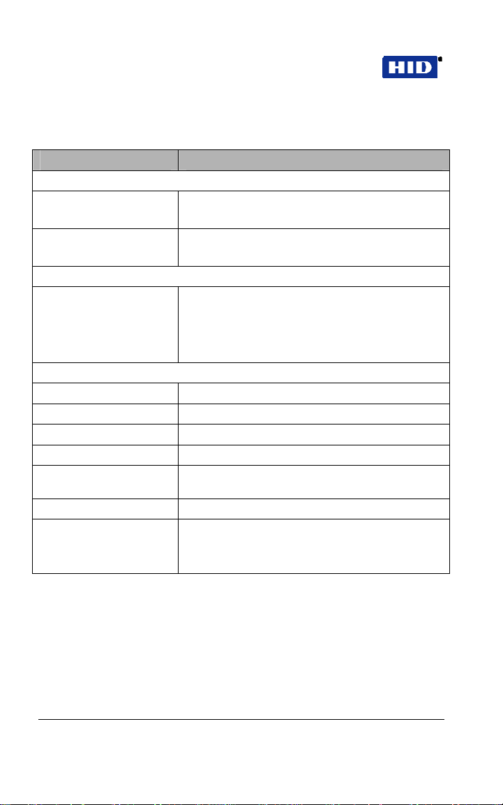
2.4 SPECIFICATIONS
CATEGORY REQUIREMENTS
Environmental
Operating Temperature –31F to +150F
(-35C to +66C) @ 30 VDC
Operating Humidity 5% to 95% relative humidity,
non-condensing
Electrical
Power Supply/Current
Requirements
Mechanical
Height 5.25 in (13.3 cm)
Width 2.75 in (7 cm)
Depth 1.625 in (4.1 cm)
Relay Outputs
Main Relay, Aux Relay Form C (switches up to 1A inductive load, 2A
Sounder 4000 Hz, defeatable
LEDs Bi-Color (red/green)
10 - 15V DC, linear, filtered and regulated power
supply recommended 150 mA for the EntryProx
unit only.
Additional capacity or separate supply required for
locking device or peripherals.
resistive @ 30VDC)
Amber
Infrared
Page 6 of 58 February 7, 2007
© 2007 HID Global Corporation. All rights reserved.
Page 7

EntryProx™ User Guide Part No. 4045-905, Rev C.2
2.5 DEFAULT SETTINGS
The EntryProx unit i s shipped with the following default settings.
PARAMETER DEFAULT SETTING
Master Code (User Location 1) 1234*
Code must be changed before programming the
unit.
Main Relay energizes for 5 seconds
Audible Keypress Feedback ON
Local Propped Door Sounder activates after 30 seconds
Local Forced Door Sounder activates
immediately for
Data Output Port Infrared (IR) port
10 seconds
February 7, 2007 Page 7 of 58
© 2007 HID Global Corporation. All rights reserved.
Page 8

Part No. 4045-905, Rev C.2 EntryProx
™
User Guide
3 INSTALLATION
You can install the EntryProx unit by using a stan dard insta llation
method or a secure installation method. Both installation methods
require that you mount the EntryProx unit to a w all or gla ss
surface.
3.1 ASSEMBLY PARTS
Before you install the EntryProx, be sure that you have the correct
factory and installer supplied parts.
A. Controller Keypad Unit I. Silicone Rubber Cushion
B. Controller Keypad
Backplate
C. Cable Assemblies K. 2-pin Jumper †
D. Antenna Backplate L. Filler Piece
E. Antenna Housing M. Lithium “Coin Cell” Battery (see page
F. Blank Label
G. Mounting Screws N. Cover screws – hex and tamper.*
H. Press to Exit Label O. Hex wrench*
* - not shown in Figure 1
† - pre-installed on main board connector P2, pins 5 & 6
J. Self-Adhering Pads
10 for the Battery Caution statement)*
Page 8 of 58 February 7, 2007
© 2007 HID Global Corporation. All rights reserved.
Page 9

EntryProx™ User Guide Part No. 4045-905, Rev C.2
H
G
F
K
L
I
J
D
A
B
E
C
Figure 1 Factory Supplied Parts
3.2 INSTALLER SUPPLIED PARTS LIST
• Appropriate DC power supp ly (10-15VDC, linear type)
• Appropriate separate power supply fo r door locking uni t.
• Appropriate electrical tools
• Recommended remote antenna cable ALPHA 1294C
(22AWG)
• Wiegand interface cable ALPHA 1295C (22AWG) (o nly if
using a separate Wiegand access control panel)
• Power supply cable (18AWG - 22AWG)
• Door locking unit cable (18AWG - 22AWG)
• Door monitor cable (18AWG - 22AWG)
• Request to Exit cable (ALPHA 2421C 18AWG or ALPHA
1292C 22AWG) (only if using remote switch)
• Optional tamper screw bit (only if tamper screw is used)
• Ademco 945T or PR-20451 mag net and reed sw itch or
equivalent (for UL 294 compliance)
February 7, 2007 Page 9 of 58
© 2007 HID Global Corporation. All rights reserved.
Page 10

Part No. 4045-905, Rev C.2 EntryProx
™
User Guide
CAUTION – Replace Battery with Panasonic BR1225 only.
Use of another battery may present a risk of fire or
explosion. Battery may explode if mistreated. Do not
recharge, disassemble or dispose of battery in fire.
4 MOUNTING
If you mount the EntryProx unit to a wall, you can install an
electrical junction box to hold the uni t and th e wires in place . The
mounting hole cutouts on the backplate line up with the screw
holes on a standard junction box.
If you mount the EntryProx unit to a glass surface, DO NOT
remove the wire exits on the backplate. Remove the appropriate
wire exit cutouts located on each side of the controller keypad
case.
If your installation must comply with the UL 294 Standard
for Access Control, please read Page 14.
4.1 PRECAUTIONS FOR OUTDOOR INSTALLATIONS
Water damage is a key cause of unit malfunction, causing
corrosion or short circuits.
that will be exposed to rain o r moi s ture , ta ke the foll ow ing
precautionary measures:
1. Use silicone to seal wire runs and mounting holes
(antenna is already sealed).
When mounting the uni t in an area
2. Do NOT seal the cover and base together. Water that
enters the case must be allowed to run out at the
bottom.
3. Bend the wires to form a drip loop before they enter the
case. This will prevent water from following the wires
into the case.
Page 10 of 58 February 7, 2007
© 2007 HID Global Corporation. All rights reserved.
Page 11
EntryProx™ User Guide Part No. 4045-905, Rev C.2
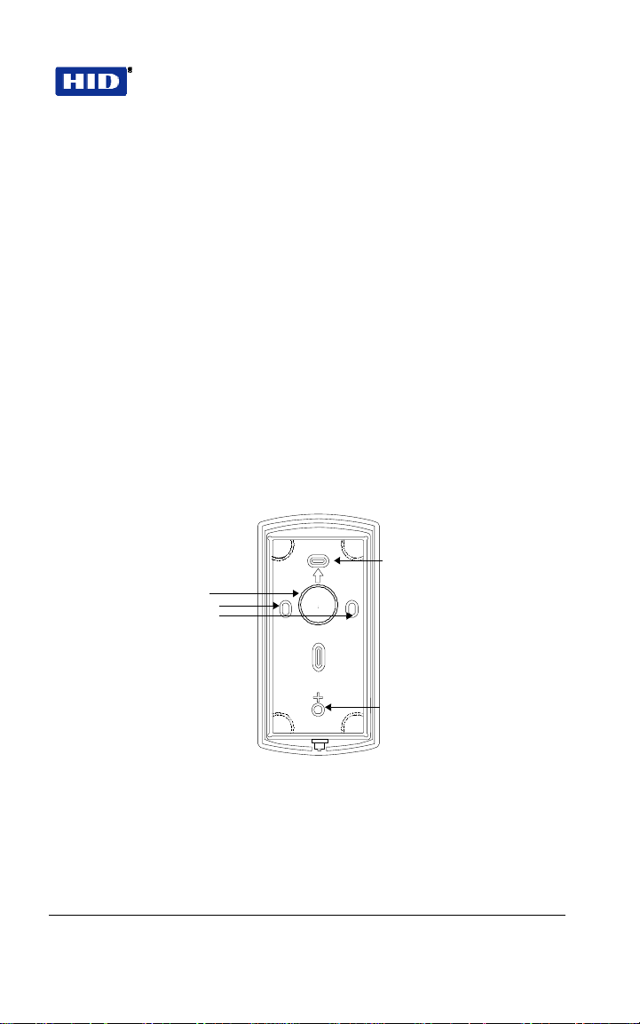
4.2 BEGINNING ENTRYPROX INSTALLATION
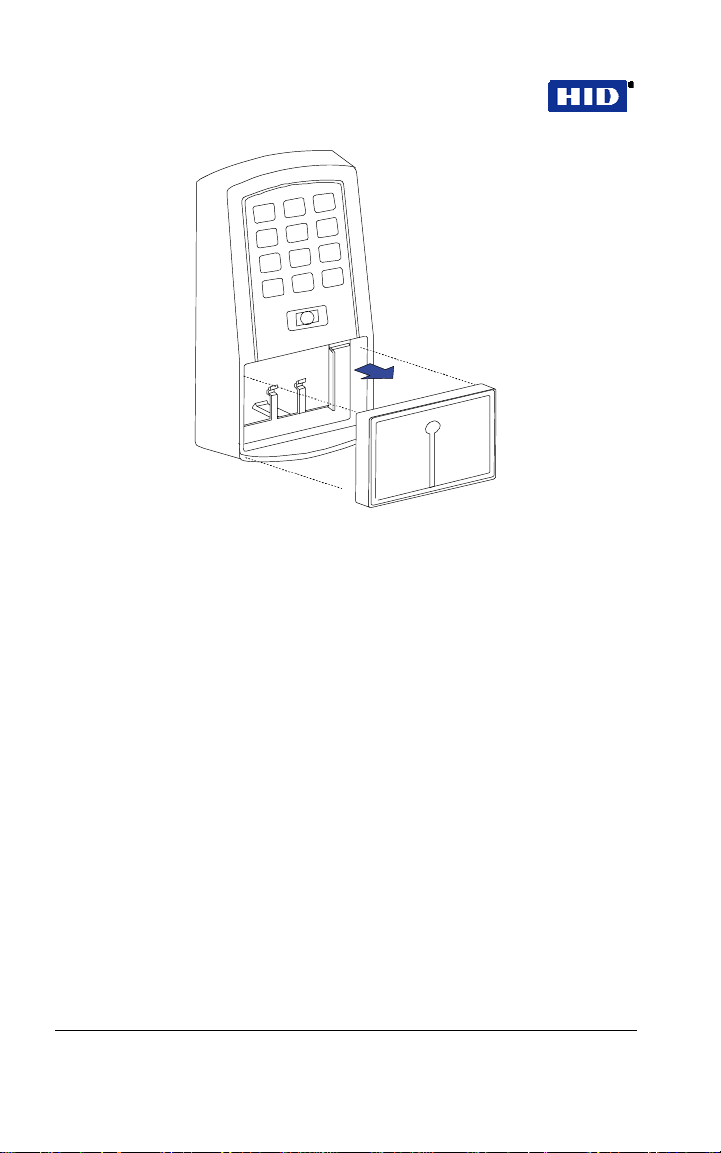
To mount the EntryProx unit, referring to Figure 2 and Figure 3 ,
follow these instructions:
1. Remove the hex screw located at the bottom of the
EntryProx unit.
2. Disconnect the backplate of the EntryProx unit from the
controller keypad.
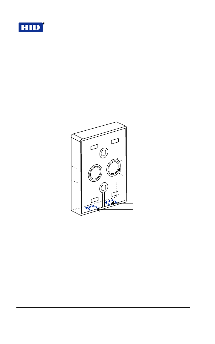
3. Remove the wire exits and mounting hole cutouts from
the backplate.
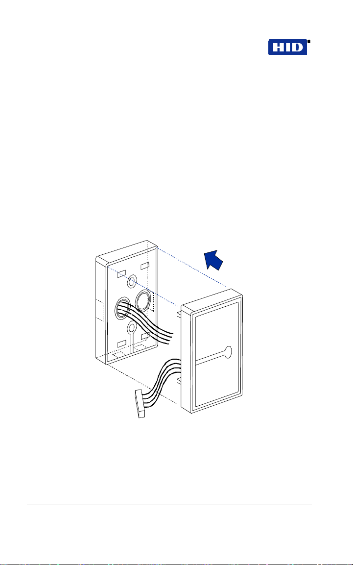
4, Pull the wires through the backplate.
5. Attach the backplate to a wall or glass surface using the
mounting screws or the self-adhesive fasteners.
Mounting Hole Cutouts
Wire Exits
Mounting Hole Cutouts
Figure 2 Removing Wiring Exits and Mounting Holes
February 7, 2007 Page 11 of 58
© 2007 HID Global Corporation. All rights reserved.
Page 12

Part No. 4045-905, Rev C.2 EntryProx
™
User Guide
Figure 3 Pulling Wires through the Backplate
4.3 CONTROLLER KEYPAD WIRING
In a standard installation, the antenna housing re mains installed in
the controller keypad, and the complete unit is installed outside of
the secured area. This is appropriate fo r interior doors or “low risk” exterior installations.
For compliance with the UL294 Standard , additional instal la tion
requirements must be met – see
FOR UL 294
To wire the EntryProx uni t for a s tanda rd ins talla tion , refe r to
Figure 4 and follow these instructions.
, page 20.
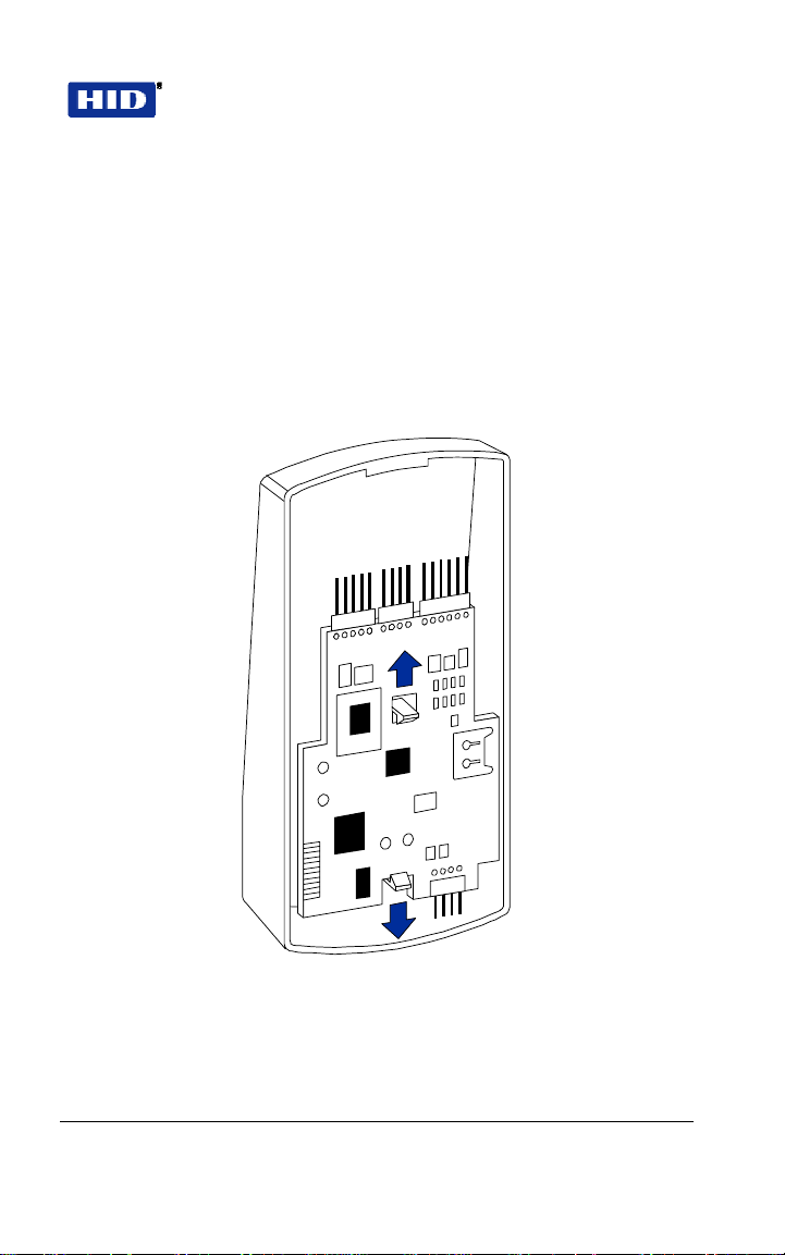
1. Touch a grounded object BEFORE touching the main
circuit board to guard against possible static
discharges.
INSTALLATION COMPLIANCE
2. Remove the main circuit board by pushing outward on
the two spring tabs in the direction shown in
Figure 4.
3. Lift the main circuit board.
4. Make the wiring connections for the door locking
devices, the power supply, and the alarm inputs and
outputs. Refer to
WIRING, page 23 for appropriate
wiring diagrams.
Page 12 of 58 February 7, 2007
© 2007 HID Global Corporation. All rights reserved.
Page 13
EntryProx™ User Guide Part No. 4045-905, Rev C.2
5. Reattach the main circuit board to the controller keypad
unit.
6. Attach the controller keypad unit to the mounted
backplate and secure the EntryProx unit with a hex
screw or tamper screw.
Note: A ribbon cable holds the main circuit board to the contro lle r
keypad board. DO NOT CUT OR REMOVE this cable from its
connector.
Figure 4 Removing the Circuit Board
February 7, 2007 Page 13 of 58
© 2007 HID Global Corporation. All rights reserved.
Page 14

Part No. 4045-905, Rev C.2 EntryProx
™
User Guide
4.4 CONTROLLER KEYPAD WIRING - SECURE INSTALLATION
In a secure installation, the waterproof antenna housing is
removed from the controller keypad and mou nted outside of a
secured area. The control unit is installed inside the secured area.
The blank filler piece is then inserted into the controller keypad in
its place. This is appropriate for exterior doors or “medium to
high-risk” locations.
To wire the EntryProx unit for a secure inst allation, refer to
and Figure 6 and follow these instructions.
5
1. Touch a grounded object BEFORE touching the main
circuit board to guard against possible static
discharges.
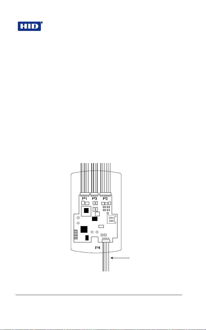
2. Remove the main circuit board by pushing outward on
the two spring tabs in the direction shown in
3. Lift the main circuit board.
4. Unplug the four-pin cable assembly from connector P4
on the main circuit board.
5. Release the antenna housing from the controller
keypad by pressing inward on the four securing tabs.
Figure
Figure 4.
6. Remove the antenna housing from the controller
keypad by pushing forward as shown in
Figure 6.
7. Insert the extra 10-inch antenna cable assembly into
connector P4.
8. Splice in additional antenna cable Alpha 1174C
(22AWG) up to a maximum of 10 feet.
Note: The Alpha 1174C antenna cable is not supplied with the
EntryProx unit.
Page 14 of 58 February 7, 2007
© 2007 HID Global Corporation. All rights reserved.
Page 15
EntryProx™ User Guide Part No. 4045-905, Rev C.2
9. Make the wiring connections for the Request to Exit
switch, the door locking devices, the power supply, and
the alarm inputs and outputs. Refer to
WIRING, page23
for appropriate wiring instructions.
10. Reattach the main circuit board to the controller keypad
unit.
11. Insert the blank filler piece into the controller keypad
unit.
12. Attach the controller keypad unit to the mounted
backplate and secure the EntryProx unit with a hex
screw or tamper screw.
13. Run the additional antenna cable to the antenna
housing location.
14. Mount and wire the antenna housing
P4 Connector Cable
Assembly
Figure 5 Removing the P4 Connector
February 7, 2007 Page 15 of 58
© 2007 HID Global Corporation. All rights reserved.
Page 16
Part No. 4045-905, Rev C.2 EntryProx
Figure 6 Removing the Antenna Housing
™
User Guide
Page 16 of 58 February 7, 2007
© 2007 HID Global Corporation. All rights reserved.
Page 17
EntryProx™ User Guide Part No. 4045-905, Rev C.2
4.5 ANTENNA HOUSING - SECURE INSTALLATION
Mount and wire the antenna housing no more than 10 fe et away
from the controller keypad unit.
To mount and wire the an tenna h ousing, refer to
Figure 8 and follow these instructions.
1. Pull the additional antenna cable through the antenna
housing’s backplate cable holes.
Cable Holes
Figure 7 and
Moisture Release
Holes
Figure 7 Mounting the Antenna Backplate
2. Position and secure the antenna backplate to the
mounting surface so that the two moisture release
holes are on the bottom.
3. Cut the plastic connector off the antenna cable
assembly.
4. Splice in the additional antenna cable. Be careful to
match the wire colors to the proper pin connectors on
the 10-inch antenna cable assembly.
February 7, 2007 Page 17 of 58
© 2007 HID Global Corporation. All rights reserved.
Page 18
Part No. 4045-905, Rev C.2 EntryProx
™
User Guide
5. Attach the antenna housing to the backplate by
inserting the four securing tabs into the backplate.
6. Seal the wire holes with silicone.
4.6 FILLER OR REQUEST TO EXIT LABEL
The filler piece replaces the antenna housing on the controller
keypad when you use the high security installation . If you do no t
plan to use the filler piece as a Request to Exit sw itch:
1. Insert the filler piece into the opening on the controller
keypad.
2. Apply the blank label.
Figure 8 Attaching the Antenna Housing
Page 18 of 58 February 7, 2007
© 2007 HID Global Corporation. All rights reserved.
Page 19

EntryProx™ User Guide Part No. 4045-905, Rev C.2
If you plan to use the filler piece as a Request to Exit switch:
1. Remove the two plastic side tabs on the filler piece.
2. Insert the silicone rubber cushion over the two
alignment pins on the switch activator.
3. Apply the “Press to Exit” label to the filler piece.
4. Insert the filler piece into the opening on the controller
keypad.
5. Refer to
Figure 11 to make the wiring connections to
the cable assembly if you are using a door contact.
6. Set the internal Request to Exit button ON, using
programming Command 30, option 7 (see
Programming Commands
).
Table 1
Cushion
Figure 9 Filler Piece and Request to Exit Switch
February 7, 2007 Page 19 of 58
© 2007 HID Global Corporation. All rights reserved.
Page 20

Part No. 4045-905, Rev C.2 EntryProx
™
User Guide
4.7 INSTALLATION COMPLIANCE FOR UL 294
The EntryProx Model 4045CGNU0 co mpl ies w ith the UL2 94
Standard for access control units in a standard, wall -mount
installation, when installed to the following spe cifica tions:
• Electric locking mechanisms may only be connecte d to the
NO contacts of the Main Relay. Locking devices requiring
an NC connection may only be used in conjunctio n with an
interposing relay mounted inside the secure area and
connected to the NO contacts of the Main Relay.
• The recommended or equivalent shielded wiring must be
used for the following applications:
Request to Exit input
cable
Wiegand data output
cable
Antenna cable extension Alpha 1294C (22AWG)
• The cable shield drain wires mu st be ground ed at the
reader end by connection to P1, Pin 4 (DC Power
configurations recommended below ) by connection to P1,
Pin 4 (DC Power Ground) using appropriate wire nuts or
crimp fittings.
• Tamper Switch must be installed in one of the
configurations recommended below, and conne cted to an
intrusion alarm system. (Refer to Figure 10 for
switch/magnet locations)
Alpha 1292C (22AWG) or 2421C
(18AWG)
Alpha 1295C (22AWG)
4.8 METAL OR PLASTIC SINGLE GANG J-BOX
1. Use an Ademco 945T magnet and reed switch (or
equivalent) with foam-backed adhesive tape.
2. Clip the screw mounting tabs from both the magnet and
reed switch using pliers or a wire cutter.
Page 20 of 58 February 7, 2007
© 2007 HID Global Corporation. All rights reserved.
Page 21

EntryProx™ User Guide Part No. 4045-905, Rev C.2
3. Remove the backing sheet from the tape on the
magnet and stick the magnet to the plastic spacer,
which is factory-installed to the back of the Keypad
board in location A (
Figure 10).
4. Stick the reed switch on the inside of the long side of
the J-box in the upper right-hand corner, using the
adhesive tape. The switch should be flush with the
edge of the J-box.
4.9 WALL MOUNTING
1. Use an Ademco® PR-20451 magnet and reed switch
(or equivalent) with foam-backed adhesive tape.
2. Remove the backing sheet from the tape on the
magnet and stick the tape to the plastic spacer, which
is factory-installed to the back of the Keypad board at
location B (
3. Drill a 3/8 inch hole in the wall behind the magnet
location, feed the switch wire through the wall and
press the switch into place.
Figure 10).
February 7, 2007 Page 21 of 58
© 2007 HID Global Corporation. All rights reserved.
Page 22

Part No. 4045-905, Rev C.2 EntryProx
Magnet B Magnet A
agnet B
M
Keypad Electronics Board
Ma in E le c tro nic s B o a rd
Keypad
lectronics Board
E
Main Electronics Board
™
User Guide
Magnet A
Batt.
Batt.
Figure 10 Tamper Switch Installation
Note: Unit is shown from the back with the base removed.
Page 22 of 58 February 7, 2007
© 2007 HID Global Corporation. All rights reserved.
Page 23

EntryProx™ User Guide Part No. 4045-905, Rev C.2
–
–
A
5 WIRING
Figure 11 illustrates the location and d escription of the four pin connec tors on
the main circuit board and its use. Conn ector P5 is not use d.
Blue – Not Used
Brown – Wiegand LED Control
White – Wiegand Data 1
Green – Wiegand Data 0
Red – Power +12 VDC
Black – Ground
Blue – Main Relay COM
Green – Main Relay NO
Gray – Main Relay NC
*Note: Rex Loop
requires NO switch;
Door Loop requires
NC switch. Connect
commons from both
loops to Loop
Common input P2, Pin
6, White.
Green
Gray – Aux Relay NC
Blue – Aux Relay COM
Brown – Rex Loop
Orange – Door Loop
White – Loop Common*
Red
Black – LED (Green +)
Antenna +
Figure 11 Pin Locator Diagram
LED (Red +)
ntenna -
Aux Relay NO
February 7, 2007 Page 23 of 58
© 2007 HID Global Corporation. All rights reserved.
Page 24

Part No. 4045-905, Rev C.2 EntryProx
™
User Guide
5.1 MAIN RELAY
The main relay for the door-locking device is wired to connector
P1 on the EntryProx main circuit boa rd .
5.2 GATE ACTUATOR
You can make the wire connections for a gate actuator by
connecting the Blue (C) wire and the Green (N/O) wire directly to
the input.
Note: DO NOT connect a power supply to the relay if you connect
a gate actuator.
5.3 AUXILIARY RELAY
The EntryProx unit has an auxiliary relay fea ture that allow s for
customized alarm programming. Pins 1, 2, and 3 on the P2
connector can be wired for one of the following alarm outpu ts:
• • Alarm shunt
• • Forced or propped door
The alarm shunt operation allows you to use the auxilia ry re lay to
bypass a door contact that is monitored by a separate alarm
system. If the entry or exit is controlled by the EntryProx unit, an
intrusion alarm will not be generated if the door is opened using an
access card or PIN number, or by pressing the REX button .
The forced or propped door ala rm allows you to use the auxiliary
relay to provide a local warning, such as an audible or vi sual
indicator if:
• • A door is opened without using an access card or PIN
number at the EntryProx unit.
• • A door is legitimately opened but is held open to o long .
Note: The auxiliary relay audible a nd visual indicators and the
door open times can be programmed. Refer to
Programming Commands
for more information.
Table 1
Page 24 of 58 February 7, 2007
© 2007 HID Global Corporation. All rights reserved.
Page 25

EntryProx™ User Guide Part No. 4045-905, Rev C.2
5.4 REQUEST TO EXIT INPUT
When the EntryProx Request to Exit (REX) input receives a
momentary switch closure, it engages the main relay for the
programmed access time. It can be connected to a wall -mounte d
exit button, to a push button under a rece p tion desk, or to the relay
output of a passive infrared motion detector mounted above the
door on the secure side. The Request to Exit input activates the
alarm shunt to prevent false alarms when personn el use th e
controlled door to exit the secured area. The Transaction Log
records all Request to Exit usages for monitoring pu rpose s.
Locate connector P2 on the main ci rcu it board and re move the 2pin jumper installed on pins 5 and 6.
Note: If you do not use a door contact, y ou n eed to twist the white
and orange wires together or the REX input will not function
properly.
Note: The door contact must be closed for the Request to Exit
feature to work properly
6 PROGRAMMING
IMPORTANT – READ BEFORE PROGRAMMING
THE ENTRYPROX UNIT
KEEP A USER LIST w hen prog rammin g ca rds and PIN codes
T
into your EntryPr o x . Write down the Use r Location, Card Number,
PIN Code and the Name of the User. Use the blank form at the
end of this book as a photocopy master. You will need this
information if you need to delete a card or PIN a t a later time .
NEW FEATURE on Rev C Model – USER LOCATION 0
RESERVED FOR MASTER CODE
This feature was added to
reduce service calls due to overwritten Master Codes. The Ma ste r
Code places the unit into programming mode. The master code
defaults to User Location 1, but afte r a Ma ster Code is
programmed into Location 0, User Location 1 can be
reprogrammed as any User Type .
NEW FEATURE on Rev C Model - FORCED CHANGE TO
MASTER CODE
February 7, 2007 Page 25 of 58
© 2007 HID Global Corporation. All rights reserved.
This feature was added to inc rease se curi ty .
Page 26

Part No. 4045-905, Rev C.2 EntryProx
The Master Code must be changed from the facto ry defaul t,
before any programming can be done. Write the new code dow n
and keep it in a safe place.
IF YOU LOSE OR FORGET THE MASTER CODE
End Users: Contact your dealer –a service call is required.
Dealers: Call HID for the procedure – and remember to bring the
proper hex key or security tool to the customer site!
™
User Guide
6.1 PROGRAMMING COMMAND SEQUENCES
Command sequences are simply a series of keypad entries to add
cards and PINs or change operating characteristics of the
EntryProx unit. There are three basic steps to programming
EntryProx, using the Keypad on the control unit:
1. Place the unit in programming mode
99 # Master Code *Press
2. Enter a Command Sequence
Press a 2-digit command number to enter cards/PINs
or specify parameters by pressin g keys in various
sequences
3. Exit programming mode
*Press to exit
6.2 LED INDICATION DURING PROGRAM MODE
A slow blinking yellow LED indicates that the unit is in program
mode.
When the yellow LED stops blinking and is OFF compl e tely , the
unit is no longer in program mode.
A steady yellow LED indicates an error condition where:
1. You are trying to enter a card or PIN which is already
stored in another User Location
Page 26 of 58 February 7, 2007
© 2007 HID Global Corporation. All rights reserved.
Page 27

EntryProx™ User Guide Part No. 4045-905, Rev C.2
2. You have pressed the wrong key in a command
sequence
Press * to clear the error condition, then enter a new
code or PIN, or re-enter the command sequence as
required. If the unit does not go into program mode,
contact your dealer or HID Techni cal Support.
6.3 CHANGING THE MASTER CODE
The EntryProx cannot be programmed before you change the
master code. This feature prevents users from leaving the default
code in the unit; thereby preventing unauthorized p ro gramming
and tampering. The steps are:
1. Enter programming mode using the default master
code in User Location 1.
Press:
99 # 1234 *
2. Enter a new master code into User Location 0. Press:
50 # 1 # 0000 # new master code * new master code *
(Code can be 1 – 6 digits. This PIN is mirrored into
User Location 1)
3. Enter a new code into User Location 1. See
PROGRAMMING SEQUENCES
, page 30.
CARD/PIN
4. Press * to exit program mode.
You can now program any user type into User Location 1, or you
can simply delete it. User Location 0 is not an access code – it is
only used to enter programming mode. Although it is not
recommended, you can also program the same PIN used in User
Location 0 as an access code in another location – it i s the only
code not checked for duplication.
It is also possible to change the master code and leave the master
code in user location 1, however, this is not recommended,
because the master code can be acci denta lly ove rw ritten.
February 7, 2007 Page 27 of 58
© 2007 HID Global Corporation. All rights reserved.
Page 28

Part No. 4045-905, Rev C.2 EntryProx
™
User Guide
6.4 BEFORE YOU START…
Before programming cards, determine:
How many cards do I
have to enroll?
How are the cards
encoded: What is the bit
format, ID numbers and
facility code?
If you have more than 50-75, you may
want to batch enroll them. If you have
fewer, you may want to program one at
a time.
If you have sequentially numbered
cards with 26-bit format and the same
facility code, you can batch-enroll them
from the keypad. Otherwise you must
program them individually or batchenroll by sequentially placing the cards
in front of the reader. Note that if you
choose to add new 26-bit cards
manually (via the keypad), the facility
code must be entered into the unit first.
For the programming sequence used to
enter the 3-digit facility code, see
1 Programming Commands
6.5 PIN CODE/CARD PROGRAMMING BASICS
PIN codes and card numbers can be programmed manually via
the keypad. Cards can also be programmed by presentation to
the reader at the correct point in the command sequence.
When adding or modifying PIN codes or cards, the user ente rs a
2-digit Command, then specifies three or four data values: a user
type, a location, and a keypad-PIN and/or card.
Table
, item 32.
6.6 USER LOCATIONS
These are the locations in the unit’s memory where Card and/or
PIN User data is stored. EntryProx User Location s are numbered
1 – 2000. User Location 0 is reserved for th e Master Code, used
for programming – Cards or PINs for normal access cannot be
entered into User Location 0.
Page 28 of 58 February 7, 2007
© 2007 HID Global Corporation. All rights reserved.
Page 29

EntryProx™ User Guide Part No. 4045-905, Rev C.2
6.7 USER TYPES
User Types determine what happens when a user presents their
card/PIN to the reader. A User Location can be programmed as
one of four specific user types:
Toggle latch strike (0) For this user-type, when the Card is
presented (or PIN is entered) the door opens fo r an ind efini te
period, until the card / code is reentered or ano ther togg le code is
entered (this is useful for deliveries, for example).
Normal access (1) This is the default user type, w hen the Card is
presented (or PIN is entered) the door open s for the du rati on of
the Main Relay time.
Download Log (2) For this user-type, when the Card is presented
(or PIN is entered) the door remains locked and the Transaction
Log is “Downloaded” to an optional Pal m PD A via th e IR L ED.
(There are three LEDs on the top of the unit - the IR LED is the
one on the right.) This code cannot be used to gain access
through the door.
Note The log is only downloaded and displayed, not erased.
Lockout (3) For this user-type, the keypad “freezes,” disallowing
all other codes, plus the door remains in the current state. During
a lockout state, card access does not continue to work. If it is
locked, it remains locked. If it is unlocked, it remains unlocked until
another Lockout code is entered, releasing it fro m Lockou t mode .
Note: Reserve this user-type for a supervisor or override function.
6.8 PIN CODES, CARDS AND COMBINATIONS
A User Location can be programmed w ith o ne of the fou r PIN
code/card combinations listed below using the programming
Commands in parentheses
(1) PIN Code ONLY (Command 50)
(2) PIN Code AND Card (Command 50 plus present card to
proximity reader)
(3) Card ONLY (Command 50 or Command 51)
(4) PIN Code OR Card (Command 52)
February 7, 2007 Page 29 of 58
© 2007 HID Global Corporation. All rights reserved.
Page 30

Part No. 4045-905, Rev C.2 EntryProx
No User Location can have the same card and/or access PIN
code as another User Location.
™
User Guide
6.9 ENTERING USER PIN CODES
EntryProx user PIN codes consist of a min i mum of one digit and a
maximum of six digits. Note that a leading “0” is considered a digit,
and that the 5-digit code 12345 is different from the six-digit code
012345. Attempting to enter a user PIN code in to me mo ry that is
already stored in a different user location causes the yellow LED
to stop blinking and remain steadily lit. If this occurs, try entering a
different user code. Repeating digits in the same code is
acceptable (ex: 121122).
7 CARD/PIN PROGRAMMING
SEQUENCES
Following are the most commonly used command se quence s fo r
programming user data into the EntryProx.
7.1 PROGRAMMING PIN + CARD
To program a user for both Code AND Card:
1. Place the EntryProx unit in program mode.
Press: 99 # Master Code *
2. On the EntryProx keypad
Press:
50 # user-type # user location # keypad PIN
* keypad PIN * <present card>
3. Press * to exit program mode.
Here is an example, assuming a master code of 2468 and
programming user 2 with PIN 1111
Press
99#2468*
50#1#2#1111*1111*Press
<present card>
*
Press
Page 30 of 58 February 7, 2007
© 2007 HID Global Corporation. All rights reserved.
Page 31

EntryProx™ User Guide Part No. 4045-905, Rev C.2
Remember to write an entry in your user list:
“User:2 Type:1 PIN:1111 Card:0056 Name: John Doe “
7.2 QUICK PROGRAMMING EITHER PINS OR CARDS
A “quick program” feature allows user data entry with minimal
keystrokes. No command number is required. This feature
programs either a card or a PIN, not a combination, and it
automatically selects a “Nor ma l” use r ac ce ss ty pe . Jus t en ter the
user’s location and the PIN (or present card):
1. Place the EntryProx unit in program mode.
Press: 99 # Master Code *
2. On the EntryProx keypad, for Code Quick Enroll
Press: u
Enroll press:
ser location # PIN * PIN * OR for Card Quick
user location # ** <present card>
3. Press * to exit program mode.
USER TYPES - REMINDER
0-Toggle 1-Normal 2-Download 3-Lockout
7.3 PROGRAMMING PIN CODE ONLY USE
To program PIN Code ONLY operation with Command 50, use the
following program sequence:
1. Place the EntryProx unit in program mode.
Press: 99 # Master Code *
2. On the EntryProx keypad
Press:
* keypad PIN *
3. Press * to exit program mode.
February 7, 2007 Page 31 of 58
50 # user-type # user location # keypad PIN
© 2007 HID Global Corporation. All rights reserved.
Page 32

Part No. 4045-905, Rev C.2 EntryProx
™
User Guide
7.4 PROGRAMMING CARD ONLY USE
To program Card ONLY use with Command 50, simply omit the
keypad PIN values from the sequence:
1. Place the EntryProx unit in program mode.
Press: 99 # Master Code *
2. On the EntryProx keypad
Press:
50 # user-type # user location # **
<present card>
3. Press * to exit program mode.
7.5 PROGRAMMING CODE OR CARD
To program a user for either Code OR Card:
1. Place the EntryProx unit in program mode.
Press: 99 # Master Code *
2. On the EntryProx keypad
Press:
52 # user-type # user location # keypad PIN
* keypad PIN * <present card>
3. Press * to exit program mode
7.6 BATCH LOAD CARDS BY KEYPAD ENTRY
Command 56 allows you to batch load mul tiple, sequ en tial 26-bi t
HID cards into the EntryProx unit. Up to 2000 u sers can be added
at one time. Cards need not be presented to the reader.
Requirements are:
• Cards must all have the same facility code.
• Cards must be sequentially numbered
• The facility code must be programmed into the unit before
any batch loading. See
Command 32 for the procedure. (This facility code canno t
be changed at a later time).
Table 1 Programming Commands,
Page 32 of 58 February 7, 2007
© 2007 HID Global Corporation. All rights reserved.
Page 33

EntryProx™ User Guide Part No. 4045-905, Rev C.2
Cards with multiple facility codes or many numbering ga ps mu st
be entered by presentation to the re ade r, using Co mmand 53.
If the Batch Loading conditions can be met:
1. Place the EntryProx unit in program mode.
Press:
99 # Master Code *
2. On the EntryProx keypad
Press: 56 # (total number of cards to be added) #
(starting user location) # card number *
repeat card number *
3. Press * to exit program mode.
7.7 BATCH LOAD BY PRESENTATION
Use Command 53 to program a batch of cards into consecutive
User Locations by specifying the starting User Loca tion , then
presenting cards or tags to the reader. Use any card fo rma t up to
37 bits. All cards are programmed alike and users are “card only.”
Card enrollment stops once the current user location exceeds
2000, or if you press any key to abort. Keep a written record as
you program cards.
Existing data in the User Locations being programmed is
overwritten, unless you present a card that is already prog rammed
into the EntryProx, in which case an error is generated. To clear
the error, press the * key; then continue presenting cards.
To batch load by presentation, follow this procedure:
1. Place the EntryProx unit in program mode.
Press: 99 # Master Code *
USER TYPES - REMINDER
0-Toggle 1-Normal 2-Download 3-Lockout
February 7, 2007 Page 33 of 58
© 2007 HID Global Corporation. All rights reserved.
Page 34

Part No. 4045-905, Rev C.2 EntryProx
2. On the EntryProx keypad
™
User Guide
Press:
53 # user type # start location # ** <present
card> <present card>
<present card>…
3. Press * to exit program mode.
7.8 DELETING USERS
To delete a user from the EntryProx, you must know the User
Location in which the information is stored.
1. Place the EntryProx unit in program mode.
Press:
99 # Master Code *
2. On the EntryProx keypad,
Press:
user location #**
3. Press * to exit program mode.
7.9 BLOCK DELETE USERS
Use Command 58 to delete all cards / PINs in a block of User
Locations. The yellow LED will blink rapi dly during the dele tion
process. It can take several seconds to delete large blocks of
users. (Entering a starting user location or number of locations
which exceeds 2000 will genera te a programming error.)
To block delete user locations, follow these steps:
1. Place the EntryProx unit in program mode.
Press:
99 # Master Code *
2. On the EntryProx keypad.
Press:
8 # start location # start location # number of
locations * number of locations*
3. Press * to exit program mode.
Page 34 of 58 February 7, 2007
© 2007 HID Global Corporation. All rights reserved.
Page 35

EntryProx™ User Guide Part No. 4045-905, Rev C.2
8 CHANGING OPERATING
PARAMETERS
Many users will use the EntryProx with the fa ctory defa ult
operating parameters. The following commands include some of
the most commonly customized parameters. For further
refinements on EntryProx operation, review the options shown in
Table 1 Programming Commands.
8.1 CHANGING THE MAIN RELAY TIME
The main relay time applies to all users 1-2000. The facto ry
default main relay time is five (5 ) se cond s. Main relay time can be
set from one to ninety-nin e seconds in one-second increments
using Command 11.
1. Place the EntryProx unit in program mode.
Press: 99 # Master Code *
2. Enter the new main relay time, in seconds (from 1 to
99). For example, to enter 10 seconds
Press:
11 # 10 # 0 # **
3. Press * to exit program mode
8.2 INVALID PIN LOCKOUT
Command 30, Option 18 allows you to enable or disa ble the
Invalid PIN Lockout (IPL) feature. This feature prevents
unauthorized persons from gaining entry by guessing PIN codes
or Master Codes. When a preset number of invalid entries is
exceeded (set by using Command 32 – option 4, default is 5) the
EntryProx will either trigger the Forced Door output, or the keypa d
will be disabled for a user -con figurable time period (select the
action, using Command 30, opti on 19, and then set lockout time
by using Command 32 – 5).
The invalid PIN code count is rese t to zero by any of the fol low ing:
• Entering a valid keypad PIN
• Presenting a programmed Prox card
February 7, 2007 Page 35 of 58
© 2007 HID Global Corporation. All rights reserved.
Page 36

Part No. 4045-905, Rev C.2 EntryProx
™
User Guide
• Entering a valid [99 # Master code*] sequence
• The expiration of the keypad time r
The Invalid PIN Lockout function disables all keypad PIN entries
with the exception of the [99 # Master Code*] sequence for the
duration of the lockout.
To clear an active timed Invalid PIN Lockout do any o f the
following:
• Disconnect power to the system
• Present a valid prox card programmed as “Card Only” or
“Card OR Code”
• Enter the [99 # Master Code *] sequence
Note that if an invalid [99# Master Code*] is entered as part of the
sequence to clear the IPL, a subsequent good [99# Ma ster Code*]
sequence will not cancel the current lockou t.
8.3 RESETTING THE MASTER CODE AND SYSTEM DEFAULTS ONLY
Command 40 erases everything from the EntryProx memory
except the user list and transaction log and restores the default
settings. This is useful if the EntryProx unit has expe rien ced
programming problems, or if you wish to delete earlier
programming.
When you do this command the following rules apply :
• If user #0 has not been programmed and user #1 is
programmed then user #0 is erased and user #1 is set to
default (1234).
• If user #0 has been programmed and user #1 has not been
modified, user #0 and user #1 are set to defaul t data (12 34).
• If user #0 has bee n programmed and user #1 has been
modified, user #0 is set to default (1234) and user #1 is no t
changed.
Page 36 of 58 February 7, 2007
© 2007 HID Global Corporation. All rights reserved.
Page 37

EntryProx™ User Guide Part No. 4045-905, Rev C.2
Note: You must change the master code after performing this
command.
1. Place the EntryProx unit in program mode.
Press: 99 # Master Code *
2. Press: 40 # 00000 # 00000 # **
3. Press * to exit program mode
8.4 ERASING ENTIRE MEMORY / RESETTING SYSTEM DEFAULTS
Command 46 deletes everything from the EntryProx memory
including the user list but not the transaction log and restores the
default settings. This is used as a last reso rt if you need to erase a
specific user and could not retrieve the Programmed User List.
After performing this command the master code must be
reprogrammed.
1 Place the EntryProx unit in program mode.
Press: 99 # Master Code *
2. Press: 46 # 00000 # 00000 # **
3. Press * to exit program mode.
8.5 TURNING KEYPRESS AUDIBLE FEEDBACK ON/OFF
The Keypress Audible Feedback command enabl es the sounder
to beep once for each key press. This feature pro vides an audible
acknowledgment that a particular key was pressed hard enough
for the unit to understand. The factory-shipped defau l t setting i s
ON, but it can be toggled ON and OFF as desired using command
30
.
1. Place the EntryProx unit in program mode.
Press: 99 # Master Code *
2. To enable this feature
Press: 30 # 0 # 1 # **
February 7, 2007 Page 37 of 58
© 2007 HID Global Corporation. All rights reserved.
Page 38

Part No. 4045-905, Rev C.2 EntryProx
3. To disable this feature
™
User Guide
Press:
30 # 0 # 0 # **
4. Press * to exit program mode
8.6 TURNING KEYPRESS VISUAL FEEDBACK ON/OFF
The keypress visual feedback feature ligh ts the LED on ce fo r each
key press. This feature provides a visual acknowledgment that a
particular key was pressed hard e nough for the unit to unde rstand.
The factory-shipped default setting is ON, but it can be toggled ON
and OFF as desired.
1. Place the EntryProx unit in program mode.
Press:
99 # Master Code *
2. To enable this feature
Press:
30 # 1 # 1 # **
3. To disable this feature
Press: 30 # 1 # 0 # **
4. Press * to exit program mode
8.7 AUTO ENTRY ENABLE
This function is not recommended for use, as it lowers the overall
security of the unit and affects programming sequences ending
with the * key. It is set with the 30# command (Set/Clear Standard
Options). When this feature is enabled, any PIN co de the same
length as the master code does not require the * key. Lea ve this
feature in the default mode, which is OFF.
Page 38 of 58 February 7, 2007
© 2007 HID Global Corporation. All rights reserved.
Page 39

EntryProx™ User Guide Part No. 4045-905, Rev C.2
9 DOWNLOADING DATA TO A PDA
The EntryProx unit can download a Transaction Log and a
Programmed User List to an optional Palm Personal Digital
Assistant (PDA) via the IR LED. There are three LEDs on the top
of the EntryProx unit - the IR LED is the one on the right.
9.1 USING THE DCD PROGRAM
The Data Collection Device (DCD) Application is provided as a
free download on the HID Website
(http://www.hidcorp.com/downloads/en try proxd cd ). The DCD
application is downloaded to a PC, and is then download ed to th e
Palm via the cradle or IR interface . Down load instru ctio ns and a
list of compatible Palm models are shown on the website. Refer to
the Palm user documentation for instructions on how to operate
the Palm PDA, how to install programs, and for the location of the
Palm IR Receiver.
1. Touch the Data Collection icon on the PDA screen.
2. The program will start, displaying three menu options:
Retrieve, Files, and Settings
3. Click on Settings to be sure the following parameters
are selected:
Comm Method – Ir Channel 2
•
• Comm Speed – 19200
February 7, 2007 Page 39 of 58
© 2007 HID Global Corporation. All rights reserved.
Page 40

Part No. 4045-905, Rev C.2 EntryProx
™
User Guide
• Protocol – Printer
• Timeout (Seconds) – 30
4. To download data from the EntryProx Unit to the Palm:
•
Touch Retrieve on the PDA screen
• Place the Palm IR receiver within 1/2” of the
EntryProx IR LED (to the right of the yellow LED)
• Enter the required command sequence at the
EntryProx keypad
You have 30 seconds to enter the command sequen ce
after entering the receive screen. If the data begins to
send before you press Retrieve, then you will miss the
beginning of the data.
5. Command sequences are described in detail in the
following sections.
Page 40 of 58 February 7, 2007
© 2007 HID Global Corporation. All rights reserved.
Page 41

EntryProx™ User Guide Part No. 4045-905, Rev C.2
9.2 SELECTING TRANSACTION LOG INFORMATION
You can selectively program specific transaction events to be
included (or not) on the Transaction Log. By “masking” out certain
events, you direct the unit not to save those even ts in memo ry and
thus they do not appear in the log. The factory defaul t is for all
transaction events to be saved in memory and included in the log.
The procedure follows:
1. Place the EntryProx unit in program mode.
Press: 99 # Master Code *
2. To turn OFF an event (keep it from being
stored/logged)
Enter:
73 # Event Code # 0 # **
3. To turn an event ON
Enter:
73 # Event Code # 1 # **
4. Press * to exit program mode.
The Event Code is a two-digit number that represents a specific
transaction as listed in the follow ing table .
February 7, 2007 Page 41 of 58
© 2007 HID Global Corporation. All rights reserved.
Page 42

Part No. 4045-905, Rev C.2 EntryProx
™
User Guide
The following transaction events can be set/cleared (saved/not
saved) and therefore downloaded/not dow nloade d.
EVENT CODE TRANSACTION EVENT
01 Access Denied
02 Program Denied
04 REX (Request to Exit)
05 Door Ajar
06 Door Closed
07 Forced Door
10 Error Lockout Activated
12 Facility Code Access
16 Download (to PDA)
17 Access
20 TGL ON (Toggle ON)
21 TGL OFF (Toggle OFF)
24 Lo ON (Lockout ON)
25 Lo OFF (Lockout OFF)
27 MSMTCH (Mismatch on Card and Code entry)
29 Program mode started
30 Log erased
Page 42 of 58 February 7, 2007
© 2007 HID Global Corporation. All rights reserved.
Page 43

EntryProx™ User Guide Part No. 4045-905, Rev C.2
10 DOWNLOADING A
TRANSACTION LOG
Using the optional Palm PDA w ith the DCD Pr ogra m , y ou can
download and display a Transaction Log via the EntryProx IR port.
Transaction Logs can be downloaded using two different methods,
(1) by programming a card or code to “Download” the transaction
log to the PDA and (2) by placing the EntryProx unit into program
mode and manually entering the Display Transa ction Log
command.
10.1 INITIATE A TRANSACTION REPORT “DOWNLOAD”
1. Place the EntryProx unit in program mode.
Press:
99 # Master Code *
2. For a CODE DOWNLOAD
Press: 50 # 2 # user location # code * code *
3. For a CARD DOWNLOAD
Press: 50 # 2 # user location # ** <present card> and
then present the card at the proximity reader.
4. Press * to exit program mode
Note: Entering the programmed PIN code o r presen ting the card
subsequently causes the unit to download a Transaction Log to
the optional PDA.
10.2 MANUALL Y DOWNLOADING A TRANSACTION LOG
1. Place the EntryProx unit in program mode.
Press: 99 # Master Code *
2. Touch
February 7, 2007 Page 43 of 58
Retrieve on the PDA screen
© 2007 HID Global Corporation. All rights reserved.
Page 44

Part No. 4045-905, Rev C.2 EntryProx
™
User Guide
3. Place the Palm IR receiver within 1/2” of the EntryProx
IR LED (to the right of the yellow LED)
4. On the EntryProx, press
The PDA will display a progress bar while collecti ng the
data, and when done will display
(download). You can touch
wait for the unit to time out.
When prompted for a Session Name, you can place
your stylus on the line containing the date information
and add to it or replace it with descriptive text.
70 # 0 # 0 # **
5. Press * to exit program mode
The 70 command is logged in the transaction buffer (in
memory), providing a reference as to when the log wa s
downloaded.
Log.
Figure 12 shows a sample Tran sa cti on
End of Dump
Close/Stop on the PDA or
Figure 12 Transaction Log
Page 44 of 58 February 7, 2007
© 2007 HID Global Corporation. All rights reserved.
Page 45

EntryProx™ User Guide Part No. 4045-905, Rev C.2
The Palm PDA will store reports after they are
downloaded.
To view a stored report, touch
from the list and click
selections are
Action. The drop-down menu
Info, View Remove and .
Files
, select a report
• Info gives the time and date the report was
recorded.
• View displays the report.
• Remove allows you to delete the report.
The top line of the screen shows the current line and
total number of lines as yo u scroll or page up and down
through the report.
Here is a description of the report layout:
• Top line – Current Line/Total Lines
• Second line – Session Data
• Transaction lines – Time, Date, User Location,
Action
Time: 24-hour format
Date: mm/dd/yyyy
User Location: 0-2000
Action: Describes each event
10.3 ERASIN G A TRANSACTION LOG
The Transaction Log should be erased from memory in the
EntryProx after being downloaded to prevent conflicting logs. To
erase the log, enter the following sequence:
1. Place the EntryProx unit in program mode.
Press: 99 # Master Code *
2. To erase the transaction log
Press:
3. Press * to exit program mode
February 7, 2007 Page 45 of 58
76 # 00000 # 00000 # **
© 2007 HID Global Corporation. All rights reserved.
Page 46

Part No. 4045-905, Rev C.2 EntryProx
™
User Guide
10.4 DOWNLOADING A PROGRAMMED USERS LIST
The Programmed Users List can be downloaded to the op tiona l
Palm PDA via the unit’s IR LED. The list identifies the user
location for each user’s data. It also displays user locations that
are not programmed, so to avoid an unnecessarily long file, the
download can be stopped when a sufficient percen tage of reco rds
have been processed. The percentage of re cord s downloaded is
continually updated during the download process.
1. Place the EntryProx unit in program mode.
Press: 99 # Master Code *
2. Touch Retrieve on the PDA
3. Hold the optional PDA up to the EntryProx IR port
steadily (about ½ inch away; the IR port is located to
the right of the yellow LED)
4. Then, on the EntryProx, press
The PDA will display a progress bar while collecti ng the
data (Retrieving users %) and when done will display
End of Dump Close/Stop (download). You can touch
on the PDA or wait for the unit to time out. When
prompted for a Session Name, you can place your
stylus on the line containing the date information and
add to it or replace it with descriptive text.
Page 46 of 58 February 7, 2007
© 2007 HID Global Corporation. All rights reserved.
25 # 0 # 0 # **
Page 47

EntryProx™ User Guide Part No. 4045-905, Rev C.2
5. When the list is complete, press * to exit program
mode.
Here is a description of the Report Layout:
Top line – Title
•
Second line• – Session Data
Column 1• – User location
Column 2• – user type (see table)
Column 3• – pin code
Column 4• – site code/card number
11 WIEGAND MODE
If you program the EntryProx unit to operate in Wiegand mode
with a separate access control panel, the following features are
not accessible:
• The EntryProx unit does not control door lock or unlocking
operations.
• The EntryProx unit is not able to store codes in memory.
• The main and auxiliary relay functions are turned off.
• The door monitor and Request to Exit inputs are disabled.
For more information on progra mming the EntryProx unit for
Wiegand operation, please conta c t your local distributor.
February 7, 2007 Page 47 of 58
© 2007 HID Global Corporation. All rights reserved.
Page 48

Part No. 4045-905, Rev C.2 EntryProx
™
User Guide
11.1 PIN CODE OUTPUT IN WIEGAND MODE
The system transmits keypad PIN s w hile operating in Wiegand
mode by processing any digit sequence terminated w ith the [* ] key
as 26-bit Wiegand data. The curren t fa cili ty code (se t usi ng Cod e
32 - 2) will be used. Entering any PIN over 65535 will cause an
error condition and no data will be sent.
Because keypad data is sent in a card data format, it may not be
possible for some panels to pe rform CARD AND CODE operation
(requiring both) to gain access. If your panel cannot accept and
interpret 26-bit format as PIN data, be sure to configure the user at
the PC host software by entering the code in to th e CARD data
field for that user, not the keypad PIN number field.
11.2 LED Control Options for Wiegand Mode
The combined programming for Op tion s 30#9 – 30#1 2 and the
Wiegand LED Control line affect the LED display in Wiegand
mode. The following table shows how the LED w ill behave whe n
the LED control line is open (normal) or grounded (asserted by the
access control panel).
G = Green, R = Red, Y = Yellow. See the following section for
more on option progra mming.
Opt 9
Opt 10
Opt 11
Opt 12
Led Ctl Open
Led Ctl Gnd
0 0 0 1 1 1 1 1 1
- - - 0 0 0 1 1 1
0 1 1 0 1 1 0 1 1
- 0 1 - 0 1 - 0 1
G G R R Y
G R Y R G
Page 48 of 58 February 7, 2007
© 2007 HID Global Corporation. All rights reserved.
Page 49

EntryProx™ User Guide Part No. 4045-905, Rev C.2
12 PROGRAMMING COMMANDS
Read the following table before completing progra mmin g of your
EntryProx unit; it describes various p ro gramming commands and
how to execute them. As with the previously described
commands, you must first press 99 # (Master Code) * to enter
programming mode, enter the desired command se quen ce, and
then press * to exit programming mode. “Ref” number is for
reference only, not to provide an ordered sequen ce of commands.
Table 1 Programming Commands
IF YOU WANT
Ref PRESS DETAILS
TO
1 Enter program
mode
2 Program new
master code into
user location 0
3 Set main relay
time
4 Set AUX relay
output
5 Delete users User Location #
6 Download a
transaction Log
99 # (Master
Code) *
50 # 1 # 0000 #
master code *
master code *
11 # tt # 0 # ** tt = 1 - 99 seconds
15 # output
mode
# 0 # **
**
70 # 0 # 0 # ** Hold optional Palm PDA
yellow LED blinks slowly
example: 4321 master code
(50 # 1 # 0000 # 4321 * 4321
*)
Output Modes:
0 = disabled,
1 = shunt,
2 = forced door,
3 = propped door
Example:
To delete user 100, press:
100#**
IR receiver near the
EntryProx IR LED.
February 7, 2007 Page 49 of 58
© 2007 HID Global Corporation. All rights reserved.
Page 50

Part No. 4045-905, Rev C.2 EntryProx
IF YOU WANT
Ref PRESS DETAILS
™
User Guide
TO
7 Set/clear standard 30 # option # s/c See the following Option
option # ** numbers and descriptions.
†† If Option 30# 14# is enabled, this sets the time that a card must be
removed from the RF field before it can be re-read. If option 30#14# is
disabled, this sets the time between successive readouts, used in either
standalone or Wiegand mode.
Option Number/Description
0: Audio keypress feature
1: Visual keypress feature
2: Auto entry enable
3: Stand-alone/Wiegand operation
4: Facility code access (26-bit cards only).
Note: this disables the “toggle” card function. 0 = OFF/1 = ON
5: Forced door audio alert
6: Propped door audio alert
7: Internal Request to Exit switch
8: US/EU Daylight Savings rollover dates
9: Wiegand red LED enable
10: Wiegand red LED active state
11: Wiegand green LED enable
12: Wiegand green LED active
13: Automatic Daylight Savings Time change
14: Prox card antipassback select
18: Invalid PIN lockout select
19: Invalid PIN lockout action
8 Download
programmed user
list
25 # 0 # 0# ** Hold optional Palm PDA IR
Set/Clear
0 = OFF/1 = ON
0 = OFF/1 = ON
0 = OFF/1 = ON
(Recommend OFF)
0 = standalone/1=Wiegand
0 = OFF/ 1 = ON
0 = OFF/1 = ON
0 = OFF/1 = ON
0 = US/1 = European
0 = OFF/1 = ON
0 = LOW/1 = HIGH
0 = OFF/ 1 = ON
0 = LOW/1 = HIGH
0 = OFF/ 1 = ON
0 = OFF / 1= ON (prevents
multiple card reads in
Wiegand mode)
0 = OFF / 1= ON
0 = TIMED LOCKOUT / 1 =
Forced Door Output
receiver near the EntryProx
IR LED.
Page 50 of 58 February 7, 2007
© 2007 HID Global Corporation. All rights reserved.
Page 51

EntryProx™ User Guide Part No. 4045-905, Rev C.2
IF YOU WANT
Ref PRESS DETAILS
TO
9 Download
programmed user
list (starting at a
certain user)
10 Change Wiegand
& Miscellaneous
parameters
11 Set system time 41 # hhmm # 0
12 Set system date 42 # mmddyy #
13 Set door number 43 # nnnn # 0 #
25 # 0 # start
user # **
32 # parameter
# value # **
# **
dow # **
**
Hold optional Palm PDA IR
receiver near the EntryProx
IR LED.
Parameter/Value
0, Wiegand pulse width,
default=8, 160µs, (1=20µs),
range= 1- 255
1, Wiegand interpulse
spacing, default=32, 640µs,
(1=20µs), range=1-255
2, facility code/0-225
(default = 1) (26-bit cards
only) verify!
3, Process card timer 2 – 240
in ¼ second increments,
defaults to 4 – 1 second††
4, Invalid PIN lockout
threshold 1 –50 attempts
(defaults to 5)
5, Invalid PIN lockout
duration 1 – 255 in 5 second
increments (defaults to 60 5 minutes)
hhmm = hour/minute,
24-hr format
mmddyy =
month, day, year;
dow = day of week,
1 = Sunday
nnnn = door number (for
downloaded reports)
February 7, 2007 Page 51 of 58
© 2007 HID Global Corporation. All rights reserved.
Page 52

Part No. 4045-905, Rev C.2 EntryProx
IF YOU WANT
Ref PRESS DETAILS
™
User Guide
TO
14 Set propped door 44 # ttt # 0 # ** ttt = propped door time, to
time (this sets
delay time for
both the Aux
Relay and local
sounder)
15 Set forced door 45 # ttt # 0 # ** ttt = forced door time, to
time (this sets
active time for
both the Aux
Relay and local
sounder)
16 Delete memory 40 # 00000 #
except user list 00000 # **
and restore
system defaults
(also see
command 46)
17 Delete all memory
and reset system
defaults
18 Program user: 50 # user-type #
Code ONLY
NOTE: You can
program the four
types of users
shown to the right
19 Program user: 50 # user-type #
Code AND Card
20 Program user: 50 # user-type #
Card ONLY
46 # 00000 #
00000 # **
user location #
code * repeat
code *
user location #
code * repeat
code *
<present card>
user location # *
*
<present card>
nearest 10's seconds,
entered
as 10 -990; default = 30
seconds
nearest 10's seconds,
entered
as 10 - 990; default = 10
seconds
User Types:
0 - Toggle/latch strike
1 - Normal Access
2 - Log Download
3 - Lockout
Page 52 of 58 February 7, 2007
© 2007 HID Global Corporation. All rights reserved.
Page 53

EntryProx™ User Guide Part No. 4045-905, Rev C.2
IF YOU WANT
Ref PRESS DETAILS
TO
20A Program new
master code into
user location 0
21 Program card
user manually:
Card ONLY (26bit cards ONLY)
22 Program user: 52 # user-type #
Code OR Card
23 Program a group
of consecutive
users by
presenting cards
24 Perform batch
entry of users:
Card ONLY (26bit cards ONLY)
25 Block Delete
Users
26 Quick Enroll Card User Location #
50 # 1 # 0000 #
master code *
master code *
51 # user-type #
user location #
card ID * card ID
*
user location #
code* repeat
code *
<present card>
53 # user type #
start location #
**
<present card>
<present card>
<present card>
…
56 # total count
# starting user
location #
starting card ID
* starting
card ID *
58 # start user #
start user #
number of users
* number of
users *
* * <present
card>
the card ID appears on the
card (facility code must be
entered first; see 32 # 2 #
command)
Programs card-only users.
Stops at user location 2000,
or press any key to abort.
Erases existing
programming. If an existing
card is presented, an error
will occur – press * to resume
the card ID appears on the
card; (facility code must be
entered first; see 32 # 2 #
command)
Yellow LED blinks rapidly;
allow several seconds for
large blocks of users.
Cannot delete: master user,
more than 2000 users, or
user location greater than
2000.
February 7, 2007 Page 53 of 58
© 2007 HID Global Corporation. All rights reserved.
Page 54

Part No. 4045-905, Rev C.2 EntryProx
IF YOU WANT
Ref PRESS DETAILS
™
User Guide
TO
27 Download
Transaction Log
via IR port
28 Set transaction
log mask
(set/clear event
logging)
29 Reset transaction 76 # 00000 #
Log 00000 # **
30 To exit Program * (after final yellow LED stops flashing
mode command)
70 # 0 # 0 # ** Hold optional Palm PDA IR
73 # event # set/
clear # **
Code – Transaction Event
01 – Access Denied
02 – Program Denied
04 – Request to Exit
05 – Door Ajar
06 – Door Closed
07 – Forced Door
10 – Invalid PIN Lockout
12 – Facility Code Access
16 – Download to PDA
17 – Access
20 – Toggle ON
21 – Toggle OFF
24 – Lockout ON
25 – Lockout OFF
27 – Mismatch
29 – Program Mode started
30 – Log erased
receiver near the EntryProx
IR LED.
Prevent specified
transactions from being
logged.
Set =0 (prevent)
Clear = 1(restore)
See the following
Transaction Event
Code -
list.
Page 54 of 58 February 7, 2007
© 2007 HID Global Corporation. All rights reserved.
Page 55

EntryProx™ User Guide Part No. 4045-905, Rev C.2
13 LED/SOUNDER STATUS
INDICATIONS
Table 2 LED/Sounder Indications
LED OR VISUAL/AUDIBLE
SOUNDER CONDITION
Slow blink Unit is in Program mode Yellow LED
Rapid blink Verify mode is active
Steady Program error; to clear,
Very rapid blink Memory (EEPROM)
Steady red Strike is locked Bi-Color LED
Steady green Strike is energized
Slow blinking green Transferring data to
Solid green with red
flicker
Red/green alternating Awaiting second form of
DESCRIPTION
(checking that the last
two values in sequence
match)
press *
erase is in progress
commands 40/46, 58
loop-back)
(timed or latched)
PDA
Strike toggle is unlocked
and used lockout active
ID during “Card AND
Code” access attempt
February 7, 2007 Page 55 of 58
© 2007 HID Global Corporation. All rights reserved.
Page 56

Part No. 4045-905, Rev C.2 EntryProx
™
User Guide
LED OR VISUAL/AUDIBLE
DESCRIPTION
SOUNDER CONDITION
Red blink User lockout is active
Short beep (100 ms)
every 2 seconds
Sounder 1/2 second on,
1/2 second off
3 rapid beeps after code
is entered or card is
presented
3 slow beeps (250 ms),
then a single beep
1 single beep Valid card access
and strike locked; red
LED drops out for 100
ms every second;
normal users cannot
change the state of the
relay. This also
indicates Invalid Pin
Lockout.
Propped door is active Sounder
Forced door is active
Code or Card is not
found
Self-test is complete
Page 56 of 58 February 7, 2007
© 2007 HID Global Corporation. All rights reserved.
Page 57

EntryProx™ User Guide Part No. 4045-905, Rev C.2
Instructions: Do not write on this page - use it as a photocopy
master. Copy the chart at a 200% enlargement. Make as many
copies as required to record all programmed use rs, and w rite
information in the appropriate spaces. Place the users charts in a
binder, and keep them in a secure location.
February 7, 2007 Page 57 of 58
© 2007 HID Global Corporation. All rights reserved.
Page 58

© 2007 HID Global Corporation. All rights reserved.
HID Global (California, USA)
support: tech@hidcorp.com
main: (949) 598-1600
support: 1-800-237-7769
fax number: (949) 598-1690
HID Corporation, Ltd. (Haverhill, UK)
support: eusupport@hidcorp.com
main: +44 (0) 1440 714 850
support: +44 (0) 1440 711 822
fax number: +44 (0) 1440 714 840
www.hidcorp.com
An ASSA ABLOY Group company
HID Asia Pacific Ltd. (Hong Kong)
support: asiasupport@hidcorp.com
main: (852) 3160 9800
support: (852) 3160 9802
fax number: (852) 3160 4809
 Loading...