

Page 1
®
EDGE EVO
15370 Barranca Parkway
Irvine, CA 92618-2215
USA
EDGE EVO is the next evolution in access control hardware solutions. A true IP solution that meets the demands of open architecture,
IP-centric environments, EDGE EVO provides fully distributed intelligence and decision making right to the door, leveraging the IT
infrastructure to the maximum extent possible. Wire the EDGE EVO device to Hi-O interface modules providing connectivity to electronic
door components and access control readers.
Hi-O involves devices with built-in intelligence and a CANbus that links all the devices together. Password protect or encrypt Hi-O CANbus
data trafc. Each Hi-O device (such as the push plate, electric strike, card reader and door operator) is connected to the CANbus by a
single, four-wire cable. Two of the wires supply power and the other two are used for data communication.
Hi-O Networked Controller
EH400
InstallatIon GuIde
82000-920, Rev C.0
October 2011
© 2009 - 2011 HID Global Corporation. All rights reserved.
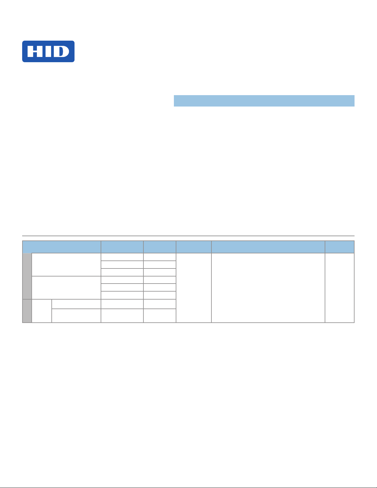
Specications
CONDITIONS VOLTAGE DC (VDC)
+12 VDC 0.14 Amp
DC Input (NSC)
Input
DC Input (MAX)
CAN DC
Output
(MAX)
Ouput
AUX 12 / 24 VDC Input +10.8 to +24 VDC 1.2 Amp*
PoE Input + 24 VDC (NOM) 0.4 Amp*
NSC = Normal Standby Condition
* Combined output ratings are not to exceed 1.2 Amps (AUX Input) or 0.4 Amps (PoE Input). X = K for Black
G for Gray
+24 VDC 0.08 Amp
PoE (+48VDC NOM) 0.05 Amp
+12 VDC 1.5 Amp
+24 VDC 1.5 Amp
PoE (+48 VDC NOM) 0.3 Amp
CURRENT
(Amp)
OPERATING
TEMPERTURE
32° - 122°F
(0° - 50° C)
CABLE LENGTH
Hi-O CAN Bus Total Length 100 ft (30 m) -
22 AWG ● 0.65mm ● 0.33mm
Maximum between drops 30 ft (10 m)
22 AWG ● 0.65mm ● 0.33mm
RJ45 = 328 ft (100 m) - Category 5 K
2
2
UL REF
NUMBER
E400CxNN
Page 2
EDGE EVO Hi-O Networked Controller
REX Switch
ted
M
a
g
n
e
H
N
Con
EH400
82000-920 C.0
1
Power Analysis
Before starting installation, determine which components will be used in the system and analyze the power requirements to avoid
over-loading the EDGE EVO Hi-O Networked Controller (EH400).
The following steps illustrate sizing power requirements for the system.
Step 1 - Identify System Components
Identify the components that will be used in the system. A typical installation may include the following components:
• Door Position Switch – Detects when the door is open or closed.
• Magnetic Lock – Holds the door locked.
• Request to Exit (REX) Switch – Unlocks the door when exiting the secured area.
• Local Exit Alarm – Sounds an alarm upon an unauthorized exit.
• EDGE EVO Hi-O Edge Door Module (EDM-M) – Connects peripheral devices to the Hi-O bus.
• EDGE EVO Hi-O Networked Controller (EH400) – Provides access control and manages all peripherals around the
door.
• Hi-O iCLASS Wiegand Reader – Provides entry into the secured area.
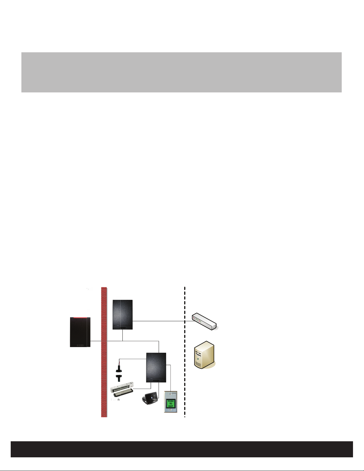
Step 2 - Create System Layout
Using the components identied in “Step 1 - Identify System Components” on page 2, create the system layout.
In this example, the EH400 is connected to the remote server through an Ethernet connection and manages door
peripherals over the Hi-O bus. The EDM-M receives inputs from the Door Position Switch and REX Switch to drive the
Magnetic Lock and Local Exit Alarm outputs.
Unprotected
Area
S
Hi-O iCLASS
Reader
i-O
Hi-O Networked
Controller
CANbus Data
Door Position
Switch
Magnetic Lock
Protected Area
Ethernet Data
Local Sounder
Exit Alarm
Door
Module
Remote Area
Ethernet Switch
Physical Access
Control Server
(real-time functions
not required )
Figure 1 - System Layout Example
INSTALLATION GUIDE2
©2009 - 2011 HID Global Corporation. All rights reserved.
Page 3
82000-920 C.0
Step 3 - Analyze Power Requirements
EDGE EVO Hi-O Networked Controller
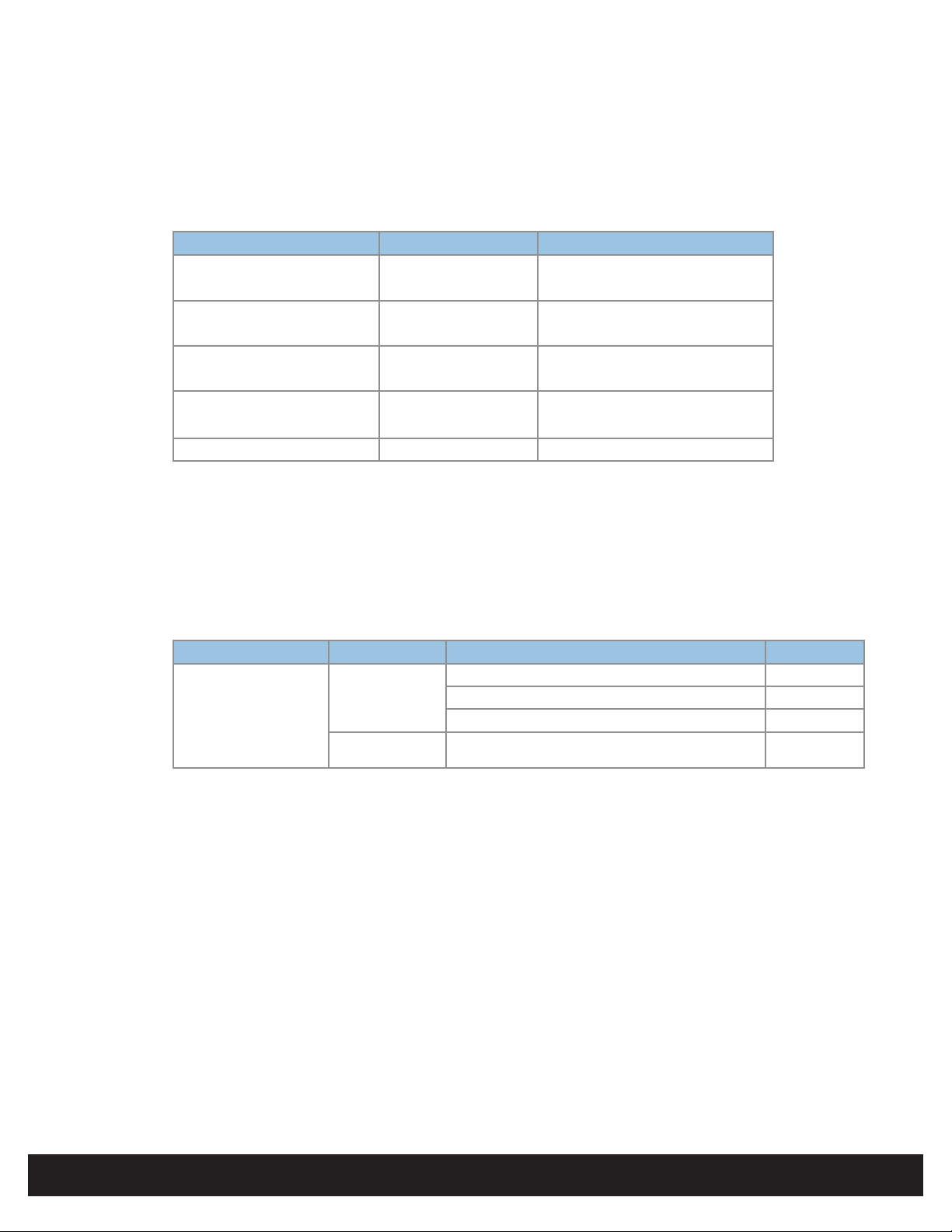
A - Door Peripheral Operational Currents
For the door peripherals identied in “Step 1 - Identify System Components” on page 2, consult the vendor data
sheets to determine the operational current draw. Typical operational current draw is provided below.
Note: See individual peripheral data sheets for actual operational current draw.
Device Conditions Typical Operational Current
Door Position Switch Vin = 12VDC 15mA
(For example, Securitron MSS) Vin = 24VDC 15mA
Mag Lock Vin = 12VDC 300mA
(For example, Securitron M32) Vin = 24VDC 150mA
REX Switch Vin = 12VDC 28mA
(For example, Securitron EEB) Vin = 24VDC 38mA
Exit Alarm
(For example, Detex 411)
iCLASS Wiegand Reader Vin = 12VDC 150mA
Consult HID datasheets for Hi-O enabled interface devices.
Vin = 12VDC
Vin = 24VDC
70mA
70mA
EH400
B - Match I/O Requirements to the Hi-O Interface Device
For the door peripherals identied in “Step 1 - Identify System Components” on page 2, the system requires
connection to a Hi-O interface device. In this example, the EDGE EVO Hi-O Edge Door Module (EDM-M) provides
general purpose I/O connectivity.
The Hi-O iCLASS reader does not require connection to the EDM-M and derives power and data connectivity from the
Hi-O CANbus directly.
Device Ports Conditions I out
Strike / Aux
EDGE EVO Hi-O Door
Module EDM-M
* Shared between each relay
** Each relay
The combined current requirement for the four door peripherals identied in “Step 1 - Identify System Components” on
page 2 is 413mA @ +12VDC,
or 273mA @ +24VDC.
The EDM-M provides sufcient power when the door peripherals are connected to the Strike/AUX relays congured for
unregulated output at +12VDC/+24VDC. Alternatively, connect the door peripherals to the Strike/AUX relays congured
for Dry contact.
The Hi-O iCLASS reader does not require connection to the EDM-M and derives power and data connectivity from the
Hi-O CANbus directly.
NC or NO
DC Output
Dry Jumpers
+12VDC unregulated (@+12VDC EDM-M input) 700mA*
+24VDC unregulated (@+24VDC EDM-M input) 700mA*
+12VDC regulated (@+24VDC EDM-M input) 310 mA*
+12 to +24VDC External 2.00 Amp**
©2009 - 2011 HID Global Corporation. All rights reserved.
INSTALLATION GUIDE 3
Page 4

EDGE EVO Hi-O Networked Controller
EH400
C - Compute and Compare Overall Current Draw
Calculate the total current draw for all door peripherals, all Hi-O interface devices, and all Hi-O enabled readers with
the following equation, adding terms as required.
I
= I
+ I
+ I
+ I
total
dps
mag
rex
alarm
+ I
Hi-O iCLASS reader
For this example, the total current draw is shown.
I
@ +12VDC = 15mA + 300mA + 28mA + 70mA + 160mA* + 40mA* = 613mA
total
I
@ +24VDC = 15mA + 150mA + 38mA + 70mA + 160mA*+ 40mA* = 473mA
total
* Notes:
a. The EDM-M draws 40mA standby current.
b. The Hi-O iCLASS reader requires a +24VDC to +12VDC converter module (EDGE EVO Hi-O Voltage Module
- EVM), adding approximately 5 to 10mA for overall load requirements.
Compare the required current draw (I
1) to select the EH400 power scheme. The CAN DC PWR Output represents the entire power output capacity of
the EH400.
Device Port Conditions V out I out
Hi-O Networked Controller
(EH400)
CAN DC PWR
Output (MAX)
+ … + I
) to the output current capacity of the EH400 (see “Specications” on page
total
EDM-M
AUX +12/24 VDC Input +10.8 to
+24VDC
PoE Input +24VDC (NOM) 400mA
82000-920 C.0
1.2Amp
In this example, the EH400 provides sufcient power when operating with +12/+24VDC auxiliary power supplies.
Directly connect the door peripherals identied in “Step 1 - Identify System Components” on page 2 to the I/O ports
of the EDGE EVO Hi-O Edge Door Module (EDM-M). Consult the EDM-M datasheet to determine the available current
capacity for the selected input power scheme of the EH400.
Ensure all door peripherals connected to the Strike/AUX relays and the Reader DC PWR Output or both do not exceed
1.2 Amps (AUX Input) or 400mA (PoE Input) combined. Alternatively, connect the door peripherals to the Strike/AUX
relays congured for Dry contact up to 2 Amps per relay.
INSTALLATION GUIDE4
©2009 - 2011 HID Global Corporation. All rights reserved.
Page 5
82000-920 C.0
M
a
g
e
ted
Hi-O N
Con
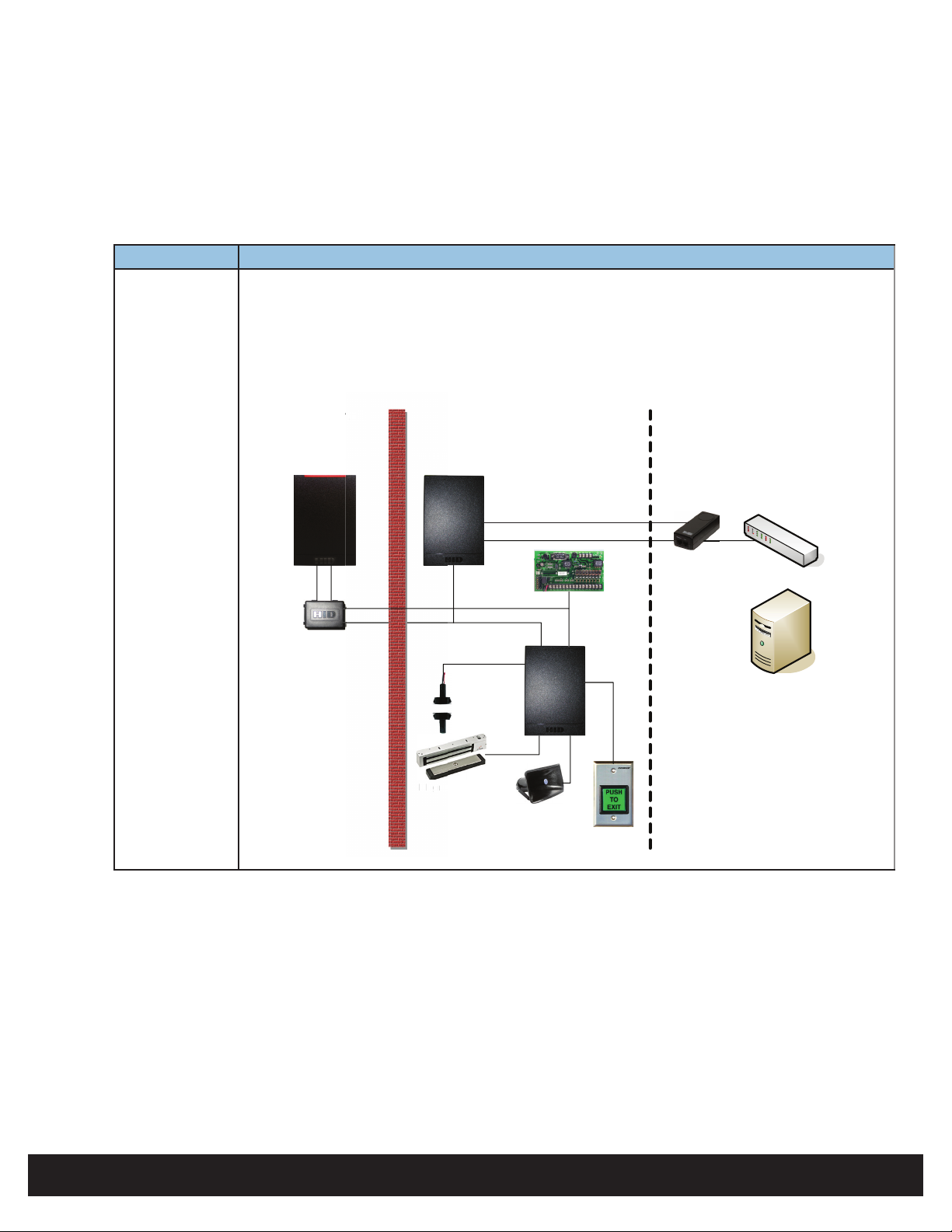
Step 4 - Select Power Scheme
Select the appropriate power scheme to meet overall current draw. Using the analysis from the previous sections equates to the
following power scheme possibilities.
Power Scheme Details
1 Hi-O CANbus power derived from an external +12VDC or +24VDC power supply. The Hi-O Networked
EDGE EVO Hi-O Networked Controller
EH400
Controller power is derived from PoE.
• Hi-O CANbus connections to the Hi-O Networked Controller shall omit the CANbus V+ and
CANbus GND output connections.
• Insert a voltage converter module between the CANBus and Hi-O iCLASS reader.
• Insert a UL294 Listed PoE Injector in the Ethernet line to power the Hi-O Networked Controller.
Unprotected
Area
Hi-O iCLASS
Reader
Voltage Module
Hi-O Networked
Controller
CANbus Data
Door Position
Switch
Magnetic Lock
n
Protected Area
Ethernet Power
Ethernet Data
Local Sounder
Exit Alarm
12 - 24VDC
Power Supply
Door
Module
REX Switch
Remote Area
UL294 PoE
Injector
Ethernet Switch
Physical Access
Control Server
(real-time functions
not required )
©2009 - 2011 HID Global Corporation. All rights reserved.
INSTALLATION GUIDE 5
Page 6

EDGE EVO Hi-O Networked Controller
ted
age
H
N
C
EH400
2 The Hi-O Networked Controller power is derived from an external +12VDC or +24VDC power supply.
• Hi-O CANbus connections to the Hi-O Networked Controller includes the CAN V+ and CAN GND
output connections.
• Insert a voltage converter module between the CANBus and Hi-O iCLASS reader.
• The Hi-O Networked Controller is connected directly to the Ethernet switch without a PoE injector.
82000-920 C.0
Unprotected
Area
Hi-O iCLASS
S
Reader
Voltage
Module
i-O
Hi-O Networked
o
Controller
CANbus Data
Door Position
Switch
Magnetic Lock
Protected Area
12 - 24VDC
Power Supply
Ethernet Data
CANbus Power
Local Sounder
Exit Alarm
Door
Module
REX Switch
Remote Area
Ethernet Switch
Physical Access
Control Server
(real-time functions
not required )
Mounting
2
Junction box not included.
INSTALLATION GUIDE6
©2009 - 2011 HID Global Corporation. All rights reserved.
Page 7

82000-920 C.0
EDGE EVO Hi-O Networked Controller
EH400
3
Wiring
CAN Termination
(Default - Installed)
Hi-O CANbus
Resistor
CAN_L
CAN_H
GND
CAN V+
GND
+DC Input
Ethernet / PoE
Auto-Detected
Ethernet
Link LED
Activity LED
4
Install to Backplate
Contact EDGE EVO through one of the following methods.
ATTENTION
Observe precautions for handling
ELECTROSTATIC SENSITIVE DEVICES
©2009 - 2011 HID Global Corporation. All rights reserved.
INSTALLATION GUIDE 7
Page 8

EDGE EVO Hi-O Networked Controller
EH400
82000-920 C.0
5
Contact
5.1 Direct Connect
If connecting EDGE EVO to a network using static IP addressing or if the Discovery GUI is not installed on the PC, use this
method.
Note: The computer must be running Windows 2000 or XP and be congured for DHCP.
1. Disconnect the computer from the network and directly connect EDGE EVO to the computer with an Ethernet cable.
2. Click Start > Run. Enter ipcong /renew ↵
3. Access a web browser and enter 169.254.242.121 into the Address eld ↵
5.2 OPIN Discovery/Update Application
Use the OPIN Discovery / Update Application on a computer to locate, connect and update EDGE EVO.
System Requirements: Java 6.0 or later. Go to www.java.com to download.
Operating Systems: Windows XP and Fedora 8.
Find the OPIN Discovery / Update Application at www.ShareMethods.com > OPIN > Firmware > 2.3.x. Save the les to your
local harddrive.
The EDGE EVO must be connected to the network, and power applied, before the device is discovered.
1. With a computer connected to the same network as EDGE EVO, double-click opin-update.jar. The OPIN Discovery / Update
Application opens and the Controller Table populates.
Note: If the Controller Table does not populate, go to Edit > Broadcast Address. The default broadcast address is
255.255.255.255. Some network switches may block this transmission. If this is the case, change the subnet to match
the network, for example 10.7.255.255. Click Save.
2. Select the desired device from the list.
3. From Path to Update Package frame, browse to the rmware location on the computer.
4. Click Install. Firmware is installed.
EH400 - Provides additional functionality to not only Install rmware, but to Changeover, and Rollback rmware
updates. Once rmware is installed, click Changeover to switch to the updated rmware. Click Rollback to switch
back to the previous rmware version.
5. View the Status Log for each status while performing Discovery and Update functions.
INSTALLATION GUIDE8
©2009 - 2011 HID Global Corporation. All rights reserved.
Page 9

82000-920 C.0
EDGE EVO Hi-O Networked Controller
EH400
6
7
Configure
The web browser will prompt for login information. From the Login screen enter admin, leaving the Password eld empty.
Follow the instructions on the web browser screen to congure EDGE EVO.
Power & Testing
Test the system once per year using the web Graphical User Interface to ensure all wiring and conguration is correct.
For additional installation information, such as PIR (Passive Infared Device) and other active Request-to-Exit (REX) devices, as
well as connecting re relays, see http://www.hidglobal.com/edgesupport.
©2009 - 2011 HID Global Corporation. All rights reserved.
INSTALLATION GUIDE 9
Page 10

EDGE EVO Hi-O Networked Controller
EH400
Hi-O Interface Modules
Hi-O interface modules are used to interface the EDGE EVO device (Controller / Reader & Module or Network Controller) with
door electronic components. Components include access control readers, strike, magnetic lock, request to exit, door position
switch, and auxillary devices.
For Hi-O interface module wiring, see their respective Installation Guides.
Go to www.hidglobal.com > Support > Document Library.
Search the document type as a Installation Guide.
Model Description Part Number
EDM-M EDGE EVO Door Module 82342
EIM-M EDGE EVO Input Module 82340
EWM-M EDGE EVO Reader Module 82360
EDWM-M EDGE EVO Door & Reader Module 82363AM
ELM EDGE EVO Lock Module 82301
EVM EDGE EVO Voltage Module 82365
82000-920 C.0
Glossary
Acronym Description Acronym Description
AC Fail AC Power Failure Input Sense GND Ground
AUX Auxillary Input or Output GRN LED Green LED Output
BATT Fail Battery Failure Input Sense GRP SEL Group Select
CAN_H Hi-O CANbus High NC Normally Closed
CAN_L Hi-O CANbus Low NO Normally Open
CLK Clock PIR Passive Infared device
COM Common PoE Power over Ethernet
Data0 Wiegand Data 0 Input RED LED Red LED Output
Data1 Wiegand Data 1 Input REX Request-to-Exit Input
Door Mon Door Monitor Input R LY Relay
DS Door Strike
INSTALLATION GUIDE10
©2009 - 2011 HID Global Corporation. All rights reserved.
Page 11

82000-920 C.0
EDGE EVO Hi-O Networked Controller
EH400
Intentional Blank
©2009 - 2011 HID Global Corporation. All rights reserved.
INSTALLATION GUIDE 11
Page 12

Regulatory
UL
Connect only to a Listed Access Control / Burglary power-limited power supply, or Listed Access Control / Burglary PoE (Power-over-Ethernet) adapter.
All National and local Electrical codes apply. Install in accordance with NFPA70 (NEC), Local Codes, and authorities having jurisdiction. Host-based security, Ethernet / Host
Communication, has not been evaluated by UL. Ethernet port has been evaluated for supplemental use only.
Indoor use only.
The EDGE EVO family has been evaluated for standalone Access Control.
Mount onto UL Listed Single-Gang electrical box.
Hi-O Networked Controller and EDGE EVO Modules are UL Listed for installation within the protected area.
All panic and alarm hardware and equipment shall be UL Listed.
All cabling and wire shall be UL Listed or Recognized and suitable for the application.
All splices and connections shall be mechanically secure and bonded electrically.
EDGE EVO was evaluated for use with all Listed HID Global Wiegand models: iCLASS, Indala Prox, HID Prox, bioCLASS, SmartID, SmartTRANS, and Mag Stripe series (with
and without keypad), up to 128-bit formats. EDGE EVO was evaluated for use with all HID Global Hi-O iCLASS readers.
Controller / Reader & Module or Network Controller are UL Listed for installation in the unprotected area, as well as within the protected area.
FCC / CANADA RADIO CERTIFICATION
CAUTION: Any changes or modications to this device not explicitly approved by manufacturer could void your authority to operate this equipment.
This device complies with part 15 of the FCC Rules. Operation is subject to the following two conditions: (1) This device may not cause harmful interference, and (2) this device
must accept any interference received, including interference that may cause undesired operation.
This device complies with Industry Canada license-exempt RSS standard(s). Operation is subject to the following two conditions:
(1) This device may not cause interference, and (2) This device must accept any interference, including interference that may cause undesired operation of the device.
CE MARKING
HID Global hereby declares that these proximity readers are in compliance with the essential requirements and other relevant provisions of Directive 1999/5/EC.
Por el presente, HID Global declara que estos lectores de proximidad cumplen con los requisitos esenciales y otras disposiciones relevantes de la Directiva 1999/5/EC.
HID Global déclare par la présente que ces lecteurs à proximité sont conformes aux exigences essentielles et aux autres stipulations pertinentes de la Directive 1999/5/CE.
A HID Global, por meio deste, declara que estes leitores de proximidade estão em conformidade com as exigências essenciais e outras condições da diretiva 1999/5/EC.
HID Global bestätigt hiermit, dass die Leser die wesentlichen Anforderungen und anderen relevanten Bestimmungen der Richtlinie 1999/5/EG erfüllen.
HID Global dichiara che i lettori di prossimità sono conformi ai requisiti essenziali e ad altre misure rilevanti come previsto dalla Direttiva europea 1999/5/EC.
Download copies of the R&TTE Declaration of Conformity (DoC) at http://certications.hidglobal.com.
JAPAN MIC
この装置は認証済みです。
TAIWAN NCC
經型式認證合格之低功率射頻電機,非經許可,公司、商號或使用者均不得擅自變更頻率、加大功率或變更原設計之特性及功能。低功率射頻電機之使用不得
影響飛航安全及干擾合法通信;經發現有干擾現象時,應立即停用,並改善至無干擾時方得繼續使用。前項合法通信,指依電信法規定作業之無線電通信。低功
率射頻電機須忍受合法通信或工業、科學及醫療用電波輻射性電機設備之干擾。
According to «Administrative Regulations on Low Power Radio Waves Radiated Devices» without permission granted by the NCC, any company, enterprise, or user is not allowed
to change frequency, enhance transmitting power or alter original characteristic as well as performance to an approved low power radio-frequency devices. The low power radio-
frequency devices shall not inuence aircraft security and interfere legal communications; If found, the user shall cease operating immediately until no interference is achieved.
The said legal communications means radio communications is operated in compliance with the Telecommunications Act.
The low power radio-frequency devices must be susceptible with the interference from legal communications or ISM radio wave radiated devices.
ACCESS experience.
© 2009 - 2011 HID Global Corporation. All rights reserved.
Check reader label for current regulatory approvals.
hidglobal.com
82000-920 Rev C.0
Patent Pending
HID Global
North America
15370 Barranca Parkway
Irvine, CA 92618
USA
Phone: 800 237 7769
Fax: 949 732 2120
Asia Pacific
19/F 625 King’s Road
NorthPoint, Island East
Hong Kong
Phone: 852 3160 9800
Fax: 852 3160 4809
support.hidglobal.com
Europe, Middle East & Africa
Phoenix Road
Haverhill, Suolk CB9 7AE
England
Phone: +44 1440 714 850
Fax: +44 1440 714 840
HID GLOBAL, HID, the HID logo, EDGE EVO and Hi-O are the trademarks or registered
trademarks of HID Global Corporation, or its licensors, in the U.S. and other countries.
 Loading...