

Page 1

HEYBROOK
TT2 INSTRUCTIONS &
CONSTRUCTION NOTES
Thank you for purchasing the Heybrook TT2 turntable. Please read the following instructions carefully to ensure that your
turntable will give you years of exceptional performance.
Page 2

Instructions for TT2 fitted with pick-up arm
1.1 Place a spirit level on the top surface of the plinth to the left of the platter, and adjust the feet until the plinth is level and
does not rock. If the TT2 is moved to a new position repeat the levelling procedure.
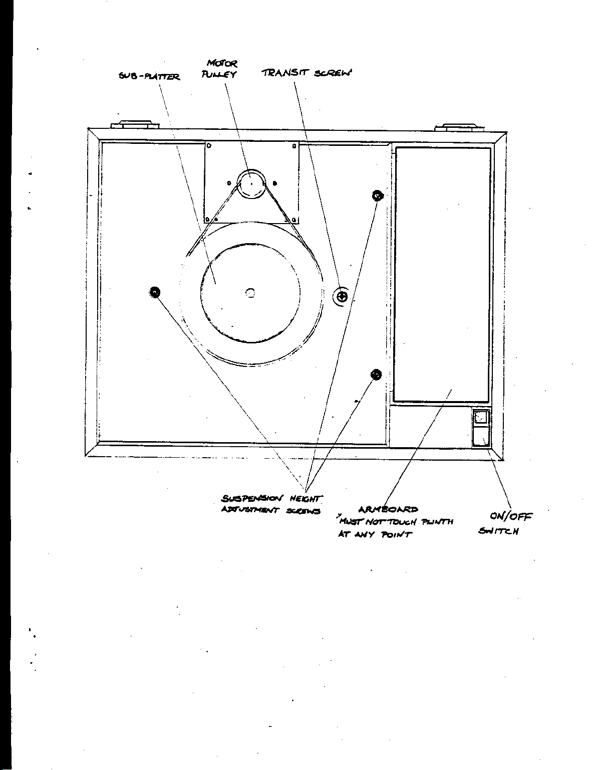
1.2 Remove the large "pozidriv" head transit screw located on the top of the plinth before using the turntable. With clean and
dry hands fit the drive belt around the sub-platter and motor pulley, making sure that the belt is not twisted. The smaller diameter
of the pulley gives a speed of 33 1/3 r.p.m., the larger diameter gives a speed of 45 r.p.m.
1.3 Carefully place the outer platter and felt mat on the sub-platter.
1.4 When placing a record on the platter please give the centre label a light tap with a finger to settle it upon the felt mat. The
motor drive is activated by the on/off switch in the front right-hand corner of the plinth. It is not necessary to switch off the motor
when changing records, as the felt mat allows you to lift the record off and replace it whilst the platter is still revolving.
1.5 Check the pick-up arm settings with the arm manufacturer's instructions.
1.6 The wires in the mains lead are coloured in accordance with the following code:
Green & Yellow Earth
Blue Neutral
Brown Live
As the colours in the mains lead of this appliance may not correspond with the coloured markings identifying the terminals in your
plug, proceed as follows:
The wire which is coloured green and yellow must be connected to the terminal in the plug which is marked with the letter E or by
the earth symbol -L , or coloured green, or green and yellow.
The wire which is coloured blue must be connected to the terminal which is marked with the letter N, or coloured black.
The wire which is coloured brown must be connected to the terminal which is marked with the letter L, or coloured red.
Use a 3 Amp fuse in your mains plug.
Page 3
Page 4
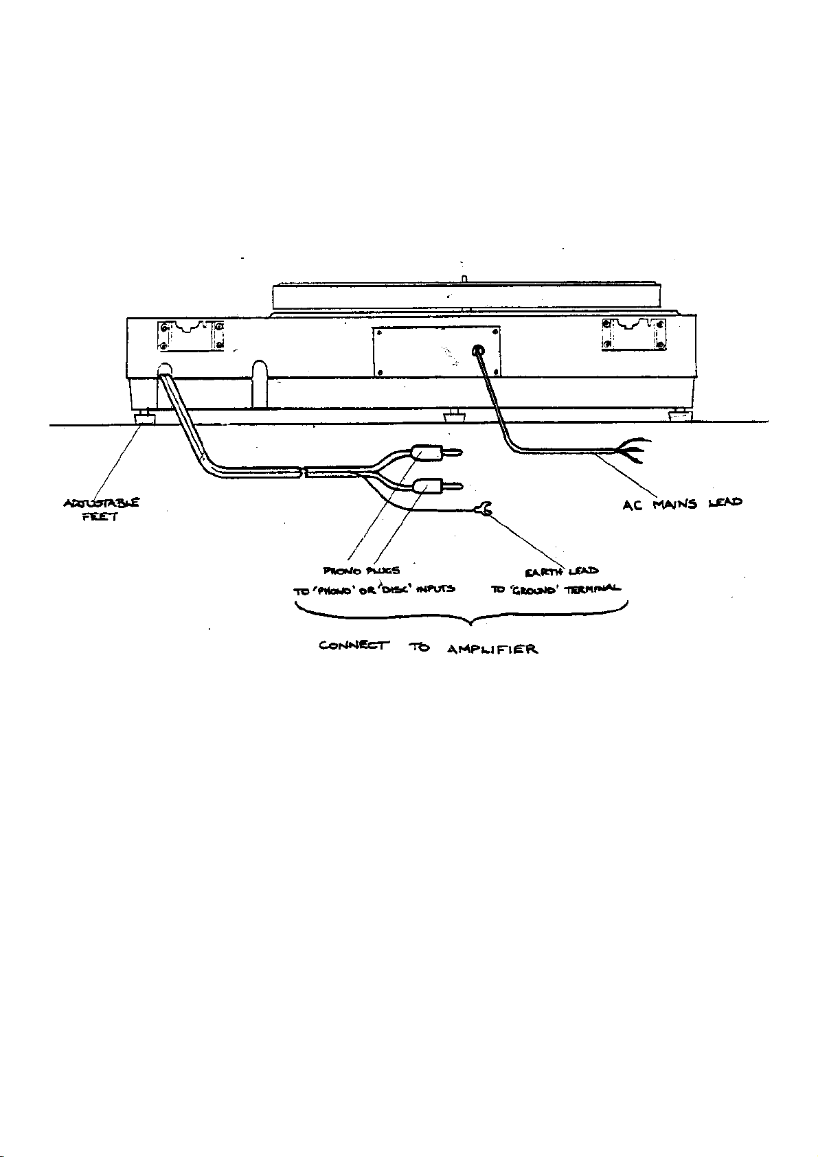
1.8 The TT2 should always be earthed to your mains supply earth, either through the mains plug or via your amplifier through
the pick-up arm earth lead. If a loud hum is noticed when turning up the volume of your amplifier it may result from the
earth loop caused by "double earthing" your turntable. Check that this is the case by removing EITHER the arm lead earth
from the amplifier, OR the mains earth green lead from the plug. The hum should then disappear. If it does not refer to the
FAULTS section after replacing the mains earth.
1.9 The motor is fitted firmly to the plinth to conduct away vibration which might otherwise find its way into the platter and
record. A slight hum may therefore be audible from the plinth with your ear held close to it, but this is normal and will not
be transmitted through your amplifier to your speakers.
Page 5

CONSTRUCTION NOTES
Instructions for fitting a pick-up arm to your TT2
DISCONNECT FROM THE MAINS SUPPLY BEFORE REMOVING THE BASE PLATE
2.1 The TT2 is available fitted with arm boards pre-cut for most popular arms. If you wish to cut your own. arm board for a
specific application, blank boards are available from your retailer. When a pick-up arm is mounted on the arm board, the arm must
be securely fastened to the board. Methods of decoupling the arm from the board, such as rubber grommets and washers, should
not be used as the TT2's suspended chassis will remove any feedback problems. Be certain to tighten all mounting screws or nuts
as tightly as possible. The am board is secured to the subchassis using a 4mm bolt and nut located on the underside of the
subchassis. This nut should be tightened fully after fitting the arm and arm cable as described below.
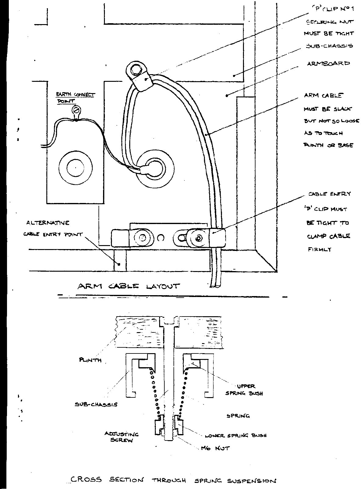
2.2 After securing the arm and arm board, it is important that the arm cable should be carefully and securely positioned so as
not to affect the operation of the subchassis. The arm cable enters the plinth via either of the two slots cut in the rear of the plinth.
The slot should be chosen which allows the cable to form a loop extending to the crossbar of the subchassis and back to the arm.
The cable should be dressed so that this loop is slack between the subchassis and the plinth, but not so slack that it touches either
the plinth or the base plate along its length. The arm cable is secured by two 'P clips, one at the entry to the plinth, and one at the
point where the arm board mounting screw projects through the subchassis. Two sizes of ‘p' clip are supplied for use with
different arm cable thicknesses at the plinth entry point. Feed the arm cables through the plinth entry ‘p' clip and screw the M4
bolt down onto the washer, but do not tighten yet. Insert a screwdriver through the elongated hole in the ‘p' clip, and use it as a
lever to tighten the clip onto the cable so that the latter is squeezed tightly. In this position tighten down the bolt using the Allen
key supplied. It should not be possible to pull the arm cable through the 'p' clip when the latter is correctly tightened. Use one of
the smaller clips at the armboard/subchassis securing bolt. The arm should be earthed to the subchassis earth as shown - if
necessary use a short piece of lead soldered to the arm earth cable.
2.3 The springing of the subchassis is factory pre-set and should remain stable for most pick-up arms. The arm cable has the
most affect on the springing, and should be dressed so that the arm board does not touch the sides of the plinth at any
point. This may be checked after fitting the platter and adjusting the suspension height - see 2.4 and 2.5. If you are not
satisfied with the operation of the suspension repeat instruction 2.2 and adjust the arm cable position until the subchassis
is springing freely.
Note that each spring has a line painted on it which should match with a red pointer on the subchassis. NEVER TRY TO TWIST
THE SPRINGS IN SITU OR THE UPPER SPRING SEATS WILL BE DAMAGED. If the springs need to be moved, tape the
sub-platter securely in place and turn the whole plinth assembly upside sown supporting the edges of the plinth either on books or
in a suitable assembly jig.
Page 6
Page 7

2.3 continued
Centre the subchassis in the plinth and remove the spring nut, lower spring seat and spring. Check that the upper spring seat is
correctly located in the upper part of the subchassis before reinserting the spring in its correct alignment and compressing it to fit
the lower spring seat and nut. The springs may be twisted in this way either side of the painted marks to achieve the optimum
centering of the arm board in its cut-out when the subchassis is affected by unusually heavy arms, or thick arm cables. The spring
which will normally have the most effect upon this is the one at the front of the plinth. Having completed the assembly under the
turntable, replace the base board and insert the feet.
2.4 The bearing is primed with specially chosen oil at the factory, and accordingly once the subchassis has been fitted to the
bearing it should not be removed if at all possible. Due to close machining tolerances the sub-platter may take some time to drop
fully into the bearing. This may be aided by placing the outer platter on the sub-platter and spinning it, but do not try to force it
down. Some oil may be inadvertently lost if the sub-platter is removed at any time - further supplies are available from the
manufacturers.
2.5 After levelling the plinth the levelling of the subchassis assembly can be carried out using the three socket-headed bolts
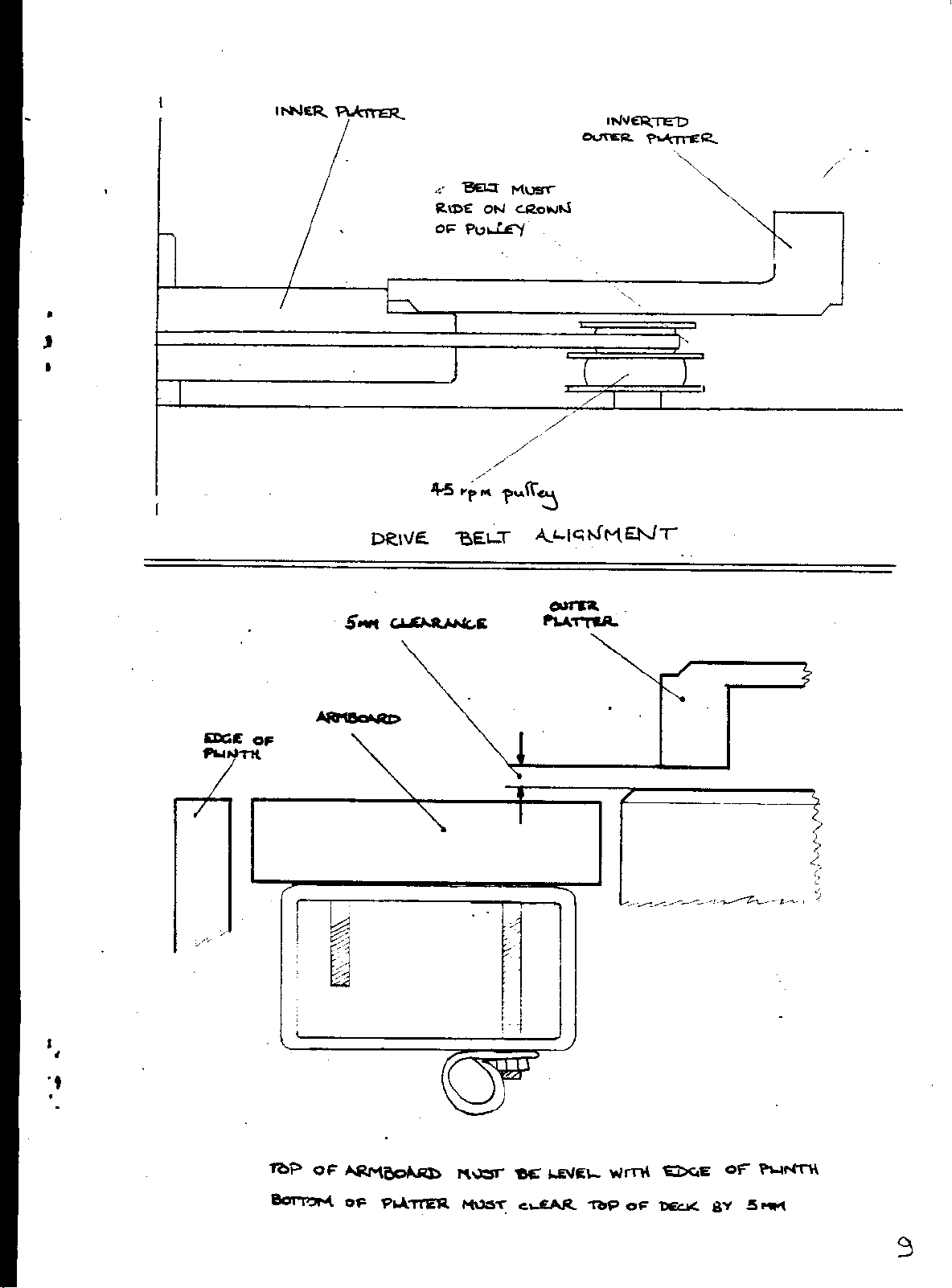
mounted in the top of the plinth. The height of the bottom of the outer platter above the top surface of the plinth should be 5 mm
and the top surface of the arm board should be level with the outer wooden rim of the plinth as shown in she diagram.
2.6 The motor supply voltage is normally set to 220/240 volts AC (110 volts AC, 60 Hz in USA and Canada). This may be
altered if required by removing the four M4 bolts holding the motor plate, and lifting the motor assembly clear of the plinth to
gain access to the motor supply circuit. Move the switch on the circuit board to the position which shows the correct voltage for
your area. Replace the motor assembly and tighten the fixing bolts fully. Replacement motor pulleys for 50 Hz and 60 Hz supply
frequencies are available from the manufacturer.
2.7 The belt should run on the crown of the 33 1/3 r.p.m. pulley without fouling the pulley flanges in normal operation. This
can be checked by placing the outer platter upside down on the sub-platter and switching on the motor to view the action of the
belt. The height and angle of the motor pulley is factory set and should not require adjustment under normal usage. If however the
belt is not running true then the four M4 screws holding the motor plate should be loosened, and the two grub screws at the front
of the plate may be adjusted using a 3 mm Allen key. Adjustment should be carried out with the platter running at 33 1/3 r.p.m.
and, after setting the grub screws, the M4 fixing belts should be tightened fully.
Page 8
Page 9

FAULTS AND REMEDIES
FAULT POSSIBLE CAUSE Remedy
3.1 Platter does not revolve
1) Power is not connected – red neon on
switch should glow.
1) Check voltage adjustment and mains connections
and plug fuse.
3.2 Turntable will not run at 45
r.p.m.
3.3 HUM can be heard through
speakers
3.4 Distorted sound
2) Remove outer platter, check
position of belt.
3)Motor pulley does not revolve
although mains connections are correct.
1) subchassis height is incorrectly set 1) See construction note 2.5. Place outer platter upside
1) Faulty earth connections 1) See Instruction note 1.8
2) Hum varies as cartridge is moved
across record
3) Make sure transit belt is fully
removed and that subchassis springs
freely
1) Check pick-up arm settings 1) Adjust according to the instructions supplied with
2) Replace belt on pulley and replace outer platter.
3)Refer to retailer
dorm on sub-platter to check running of belt.
2) Move the turntable away from amplifiers or other
electrical apparatus using motors or transformers. Try
the turntable on the opposite side of your amplifier.
3) See construction note 2.2 and 2.3
the pick-up arm and cartridge.
2) Check condition stylus. 2) Clean stylus or replace.
3) Check subchassis does not foul plinth. 3) See construction note 2.2 and 2.3
 Loading...