

Page 1
Version No.4.2
Issued September 2016
English
MINING OPERATIONS
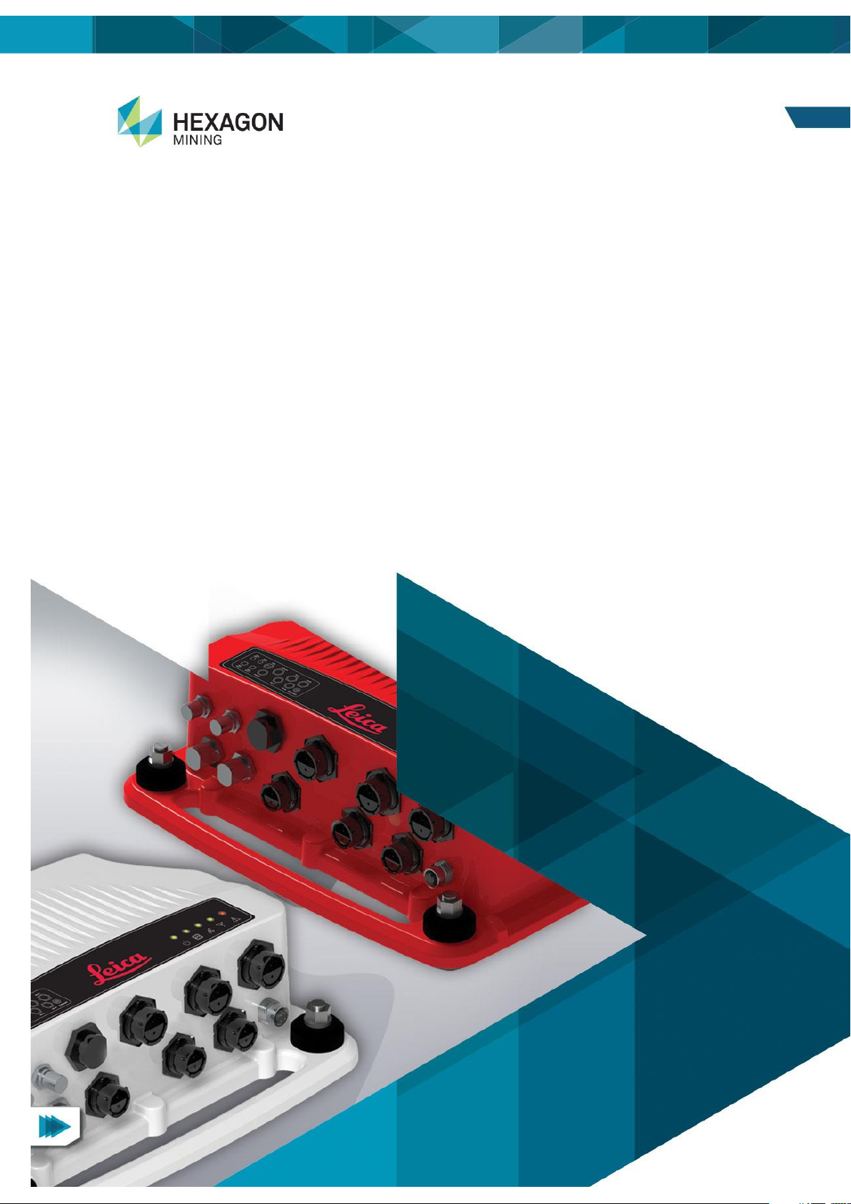
Leica Universal Hardware
Platform (UHP)
User Reference Manual
Page 2

UHP User Reference Manual v4.2
This document and any information or descriptive matter contained therein is communicated in confidence
and is the copyright property of Leica Geosystems. Neither the whole, nor any extract may be disclosed,
loaned, copied, or used in manufacturing or tendering purposes without their written consent.
© Copyright [2013-2016] Leica Geosystems Pty Ltd. All rights reserved. Leica Geosystems Pty Ltd is part of
Hexagon. Leica Geosystems and the Leica Geosystems logo are the registered trademarks of Leica
Geosystems. All trademarks or service marks used herein are property of their respective owners. Leica
Geosystems makes no representation or warranty regarding the accuracy of the information in this
publication. This document gives only a general description of the product(s) or service(s) offered by Leica
Geosystems and, except where expressly provided otherwise, shall not form part of any contract. Such
information, the products and conditions of supply is subject to change without notice.
Disclaimer: Illustrations, descriptions, and technical specifications in this document are not binding and are
subject to change without notice.
This document is optimized for printing on A4 paper.
ii Commercial in Confidence © Leica Geosystems
Page 3

Date
Document
Version
Software
Version
Author
Revision
23 Sept 2014
2 Dwayne
Martine
Manual Consolidation
19 Jan 2015
3 Dwayne
Martine
Rev. B information added
23 Jun 2016
4 M.A.Martin
Updated Wi-Fi Radio Information
in sections 7.1.5 and 7.2.5 as
follows:
Americas: Avg. TX Power
24dBm, +/- 2dB
Australia and EMEA: Avg. TX
Power 23dBm +/- 2dB
9 Aug 2016
4.1 G Tooms
Added following for FCC
compliance.
2.5 UHP Compliance Label
4.2.2 Antenna Installations:
Added Installation Warning.
4.2.2.3 Wi-Fi Antenna
Installation: Updated antenna
distance from human statement.
6.4.3 Persons in Charge of the
Product: Added antenna safety
information
Added
Chapter 11: Appendix C UHP
FCC Maximum Personal
Exposure (MPE) Calculations
27 Sept 2016
4.2 G. Tooms
Added compliance label location
information to section:
2.5 Labels on page 6
Revision History
© Leica Geosystems Commercial in Confidence iii
Page 4

Table Of Contents
1 Document Introduction ............................................................................. 1
1.1 Contacting Support ...................................................................................................... 1
1.2 Document Conventions ............................................................................................... 1
2 Universal Hardware Platform (UHP) Overview ........................................ 2
2.1 System Information ...................................................................................................... 2
2.2 Sales Region ............................................................................................................... 2
2.3 Universal Hardware Platform Low Precision With GNSS and Wi-
Fi Radio (UHP-LPG) .................................................................................................... 2
2.3.1 Components of UHP-LPG ................................................................................. 2
2.3.2 Features and Specifications .............................................................................. 3
2.3.2.1 UHP-LPG Hardware .................................................................................. 3
2.3.2.2 LEDs .......................................................................................................... 3
2.3.2.3 UHP-LPG Software ................................................................................... 3
2.4 Universal Hardware Platform High Precision With Wi-Fi Radio
(UHP-HP) ..................................................................................................................... 4
2.4.1 Components of the UHP-HP ............................................................................. 4
2.4.2 Features and Specifications .............................................................................. 4
2.4.2.1 UHP-HP Hardware .................................................................................... 4
2.4.2.2 LEDs .......................................................................................................... 5
2.4.2.3 UHP-HP Software ...................................................................................... 5
2.5 Labels .......................................................................................................................... 6
2.5.1 Compliance Label Locations ............................................................................. 6
2.5.1.1 UHP Compliance Labels by Region .......................................................... 6
2.5.2 UHP Part Number Label Location ..................................................................... 7
2.5.2.1 UHP Part Number Labels by Region ......................................................... 7
3 LED Overview............................................................................................. 8
3.1 Light Emitting Diodes (LEDs) ...................................................................................... 8
3.2 Basic Operation ........................................................................................................... 8
3.2.1 Status Codes ..................................................................................................... 8
3.2.2 Error Codes ....................................................................................................... 8
3.3 Status Sources ............................................................................................................ 9
3.4 Error Sources ............................................................................................................... 9
3.5 Status Codes ............................................................................................................... 9
3.6 UHP Status Code Chart .............................................................................................. 9
4 Hardware Installation............................................................................... 10
4.1 Before Installation ...................................................................................................... 10
4.1.1 Requirements .................................................................................................. 10
4.2 General UHP Installation ........................................................................................... 10
4.2.1 Power Cable Installation.................................................................................. 10
4.2.2 Antenna Installation ......................................................................................... 11
4.2.2.1 Antenna Application ................................................................................. 11
4.2.2.2 GNSS Antenna Installation ...................................................................... 11
4.2.2.3 Wi-Fi Antenna Installation ........................................................................ 11
4.2.2.4 External RTK Correction Antenna ........................................................... 12
4.2.3 Connection to Additional Sensors ................................................................... 12
4.2.4 Upgrade Software via USB Flash Drive .......................................................... 12
5 Care and Transport .................................................................................. 13
5.1 Transport ................................................................................................................... 13
5.2 Storage ...................................................................................................................... 13
5.3 Cleaning and Drying .................................................................................................. 13
5.3.1 Product and Accessories................................................................................. 13
iv Commercial in Confidence © Leica Geosystems
Page 5

5.3.2 Damp Products ................................................................................................ 13
5.3.3 Connectors and Plugs ..................................................................................... 13
6 Safety Directions ...................................................................................... 14
6.1 General Introduction ................................................................................................... 14
6.2 Intended Use .............................................................................................................. 14
6.2.1 Permitted Use .................................................................................................. 14
6.2.2 Adverse Use .................................................................................................... 14
6.3 Limits of Use .............................................................................................................. 14
6.3.1 Environment ..................................................................................................... 14
6.4 Responsibilities .......................................................................................................... 14
6.4.1 Manufacturer of the Product ............................................................................ 14
6.4.2 Manufacturers of Non-Leica Geosystems Mining
Accessories ...................................................................................................... 15
6.4.3 Persons in Charge of the Product ................................................................... 15
6.5 Hazards of Use .......................................................................................................... 15
6.5.1 General Hazards .............................................................................................. 15
6.5.2 Mechanical Hazards ........................................................................................ 15
6.5.3 Lightning Hazards ............................................................................................ 16
6.5.3.1 Lightning Conductors ............................................................................... 16
6.5.4 Disposal ........................................................................................................... 17
6.6 Electromagnetic Compatibility (EMC) ........................................................................ 17
7 Technical Data .......................................................................................... 18
7.1 UHP-LPG Technical Data .......................................................................................... 18
7.1.1 Design .............................................................................................................. 18
7.1.1.1 User Interface ........................................................................................... 18
7.1.1.2 Dimensions .............................................................................................. 18
7.1.1.3 Weight ...................................................................................................... 18
7.1.1.4 Power ....................................................................................................... 18
7.1.2 Environmental Specifications ........................................................................... 18
7.1.2.1 Temperature ............................................................................................. 18
7.1.2.2 Protection Against Water, Dust, and Sand .............................................. 18
7.1.2.3 Humidity ................................................................................................... 18
7.1.3 Interfaces ......................................................................................................... 18
7.1.4 GNSS Technical Data ...................................................................................... 19
7.1.4.1 GNSS Receiver ........................................................................................ 19
7.1.4.2 GNSS Antenna ......................................................................................... 19
7.1.5 Wi-Fi ................................................................................................................. 19
7.1.6 FCC Statement (Applicable for U.S.) ............................................................... 20
7.2 UHP-HP Technical Data ............................................................................................ 20
7.2.1 Design .............................................................................................................. 20
7.2.1.1 User Interface ........................................................................................... 20
7.2.1.2 Dimensions .............................................................................................. 20
7.2.1.3 Weight ...................................................................................................... 20
7.2.1.4 Power ....................................................................................................... 20
7.2.2 Environmental Specifications ........................................................................... 21
7.2.2.1 Temperature ............................................................................................. 21
7.2.2.2 Protection Against Water, Dust, and Sand .............................................. 21
7.2.2.3 Humidity ................................................................................................... 21
7.2.3 Interfaces ......................................................................................................... 21
7.2.4 GNSS Technical Data ...................................................................................... 22
7.2.4.1 GNSS Receiver ........................................................................................ 22
7.2.4.2 GNSS Antennas ....................................................................................... 22
7.2.5 Wi-Fi ................................................................................................................. 22
7.2.6 FCC Statement (Applicable for U.S.) ............................................................... 23
© Leica Geosystems Commercial in Confidence v
Page 6

8 Appendix A: Copyright ............................................................................ 24
9 Appendix B: UHP Connector Pin Out ..................................................... 25
10 Appendix C: LED Fault Codes ................................................................ 26
11 Appendix D: UHP FCC Maximum Personal Exposure (MPE)
Calculations ........................................................................................................... 28
11.1 UHP Intentional Radiators ......................................................................................... 28
11.1.1 Wi-Fi ................................................................................................................ 28
11.2 MPE Calculations ...................................................................................................... 28
11.2.1 MPE Formula .................................................................................................. 28
11.2.2 Wi-Fi MPE Calculations ................................................................................... 28
12 Glossary ................................................................................................... 29
vi Commercial in Confidence © Leica Geosystems
Page 7

Contact Method
Details
Web portal
http://www.hexagonmining.com/customer-portal.htm and select
OPERATIONS SUPPORT.
Convention Example
Description
Select FILE > PRINT
Menu selections, buttons, and icons appear in bold text. In this
case, select the FILE menu and the PRINT option. Location and
capitalization of menu items may vary by mine site.
Ctrl+P
Keyboard shortcut keys. The example indicates to select and
hold down the Ctrl key and select the P key.
See xxx
Refer to
“See” indicates a reference to another section of this document.
“Refer to” indicates reference to another document.
WARNING
Warnings alert the user to dangerous procedures which could
cause injury or death.
CAUTION
Cautions alert the user to dangerous procedures which could
cause damage to equipment.
Note
Notes supply important information about a procedure which is
not covered in the procedure text.
1 Document Introduction
The Leica Universal Hardware Platform (UHP) User Reference Manual is part of Leica’s Fleet
Management System (FMS) Documentation Suite.
This manual is intended to serve as a guide to the UHP. This manual provides all instructions
required in order to operate and troubleshoot the UHP product to a basic level. This manual
provides an overview of the system together with the care and transport, technical data and safety
directions.
It is assumed an operator using this manual is familiar with:
Site-specific safety procedures, Safe Work Procedures (SWPs) and Standard Operating
Procedures (SOPs).
Hardware Installation Processes.
Note:
The document uses generic images to show general layout and generic information
for various procedures. The site-specific screen layout, menu, and procedure
information may vary from what is displayed in the manual.
1.1 Contacting Support
For all Leica Jigsaw product support:
1.2 Document Conventions
This document uses basic conventions to indicate actions:
Commercial in Confidence
© Leica Geosystems
1
Page 8
Module
Sales Region
UHP Low Precision (UHP-LPG)
Australia (RCM), U.S. (FCC), Europe (CE),
Brazil (Anatel). Additional regions will be
added on an as needed basis.
UHP High Precision (UHP-HP)
Australia (RCM), U.S. (FCC), Europe (CE),
Brazil (Anatel). Additional regions will be
added on an as needed basis.
2 Universal Hardware Platform (UHP) Overview
Note:
The images used in this manual are for reference purposes only; individual screens
and icons may differ from the actual items.
This product is intended for Professional Use only.
2.1 System Information
The Leica Universal Hardware Platform (UHP) is configured to the following four specifications:
UHP Low Precision with GNSS and Wi-Fi Radio (UHP-LPG)
UHP High Precision with GNSS and Wi-Fi Radio (UHP-HP)
2.2 Sales Region
Leica UHP is available in select regions according to the specification:
Sales Region Table
2.3 Universal Hardware Platform Low Precision With GNSS and Wi-Fi Radio (UHP-LPG)
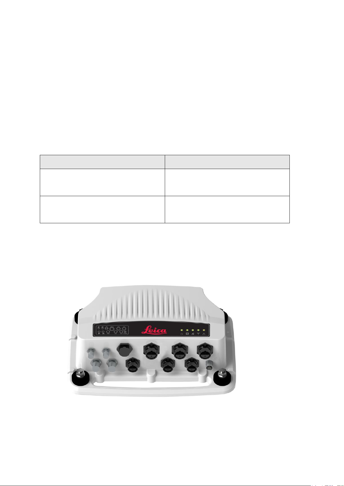
The UHP-LPG is an industrial Single GNSS receiver and communications module intended as a
part of the Leica Jigsaw Mining Solution.
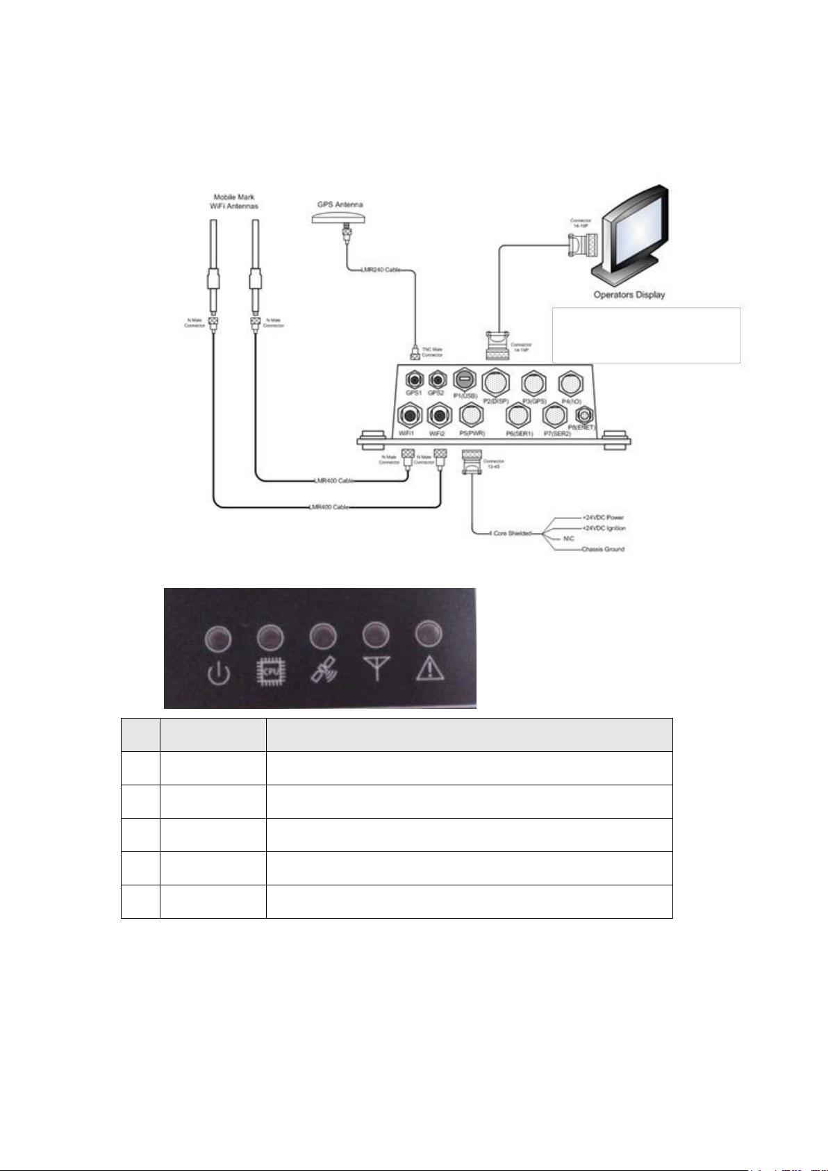
2.3.1 Components of UHP-LPG
2 Commercial in Confidence © Leica Geosystems
Page 9
#
Module
Function
1
Power LED
Lights when the Leica Jigsaw UHP-LPG has power.
2
CPU LED
Lights when the Leica Jigsaw Operating System is being used
3
GNSS LED
Lights when the Leica Jigsaw UHP-LPG has GNSS signals.
4
Radio LED
Lights when a wireless network connection is established.
5
Warning LED
Used to indicate critical warnings.
1. 2. 3. 4. 5.
2.3.2 Features and Specifications
2.3.2.1 UHP-LPG Hardware
Hardware
2.3.2.2 LEDs
2.3.2.3 UHP-LPG Software
Command line configuration.
Upgrade of software through USB.
Commercial in Confidence
© Leica Geosystems
3
Page 10
2.4 Universal Hardware Platform High Precision With Wi-Fi Radio (UHPHP)
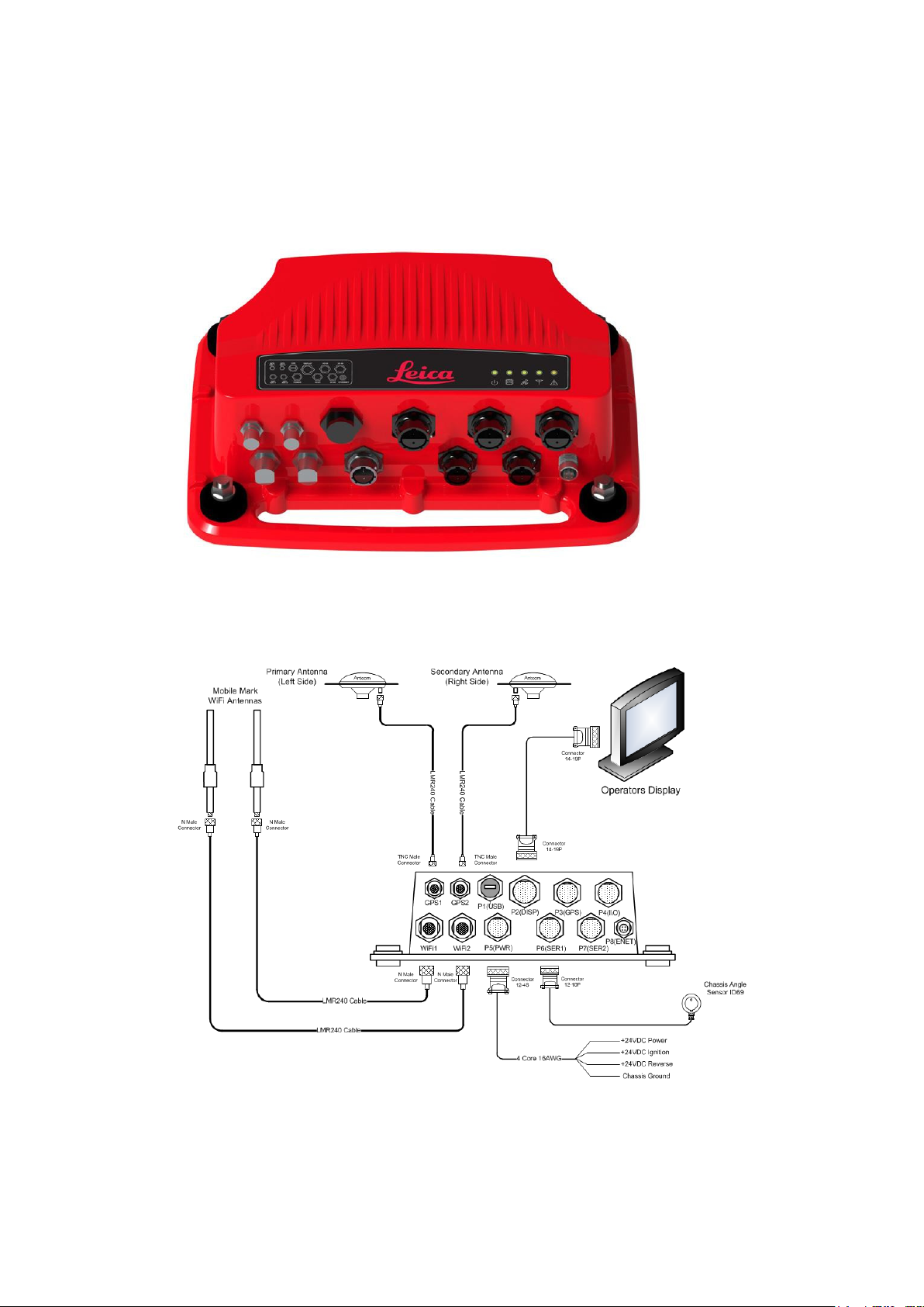
The Leica Jigsaw UHP-HP is an industrial Dual Real Time Kinematic (RTK) GNSS receiver and
communications module intended as a part of the Leica Jigsaw Mining Solution.
2.4.1 Components of the UHP-HP
2.4.2 Features and Specifications
2.4.2.1 UHP-HP Hardware
Hardware
4 Commercial in Confidence © Leica Geosystems
Page 11
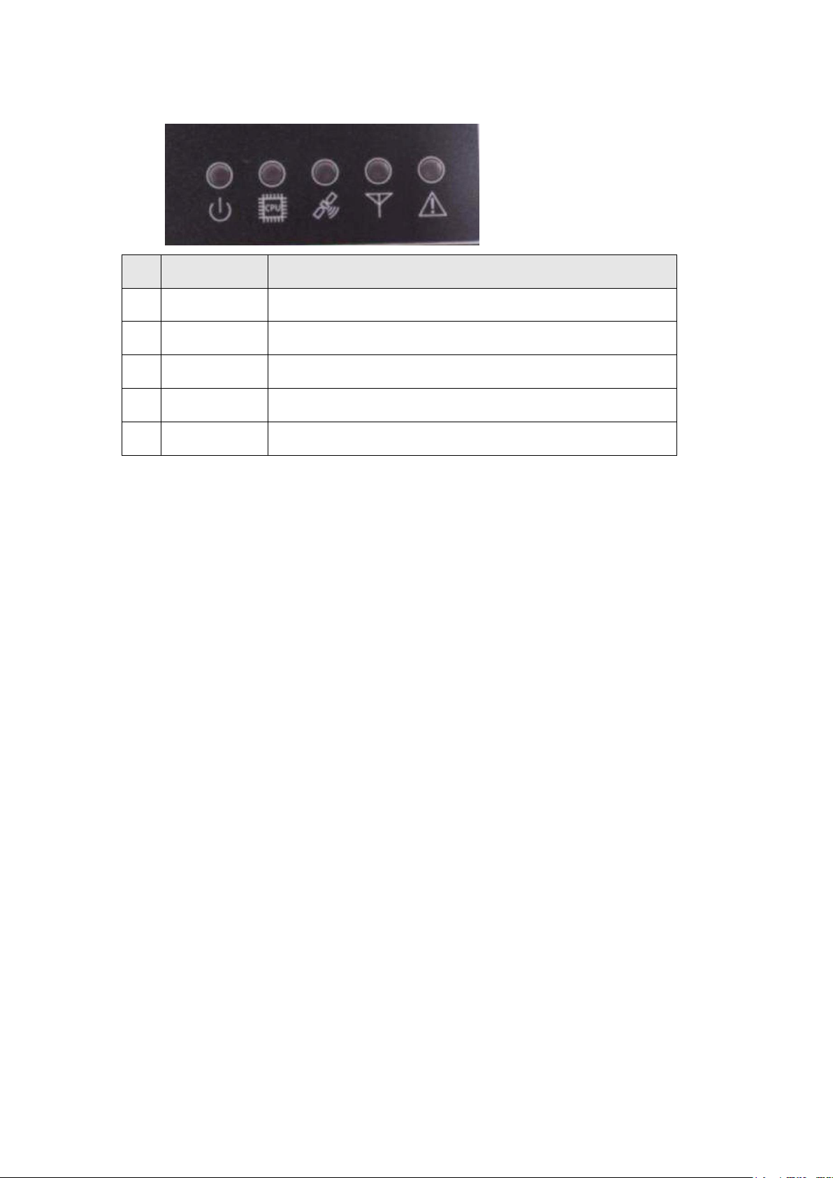
#
Module
Function
1.
Power LED
Lights when the Leica Jigsaw UHP-HP has power.
2.
CPU LED
Lights when the Leica Jigsaw Operating System is being used.
3.
GNSS LED
Lights when the Leica Jigsaw UHP-HP has GNSS signals.
4.
Radio LED
Lights when a wireless network connection is established.
5.
Warning LED
Used to indicate critical warnings.
1. 2. 3. 4. 5.
2.4.2.2 LEDs
2.4.2.3 UHP-HP Software
Command line configuration.
Upgrade of software through USB.
Commercial in Confidence
© Leica Geosystems
5
Page 12
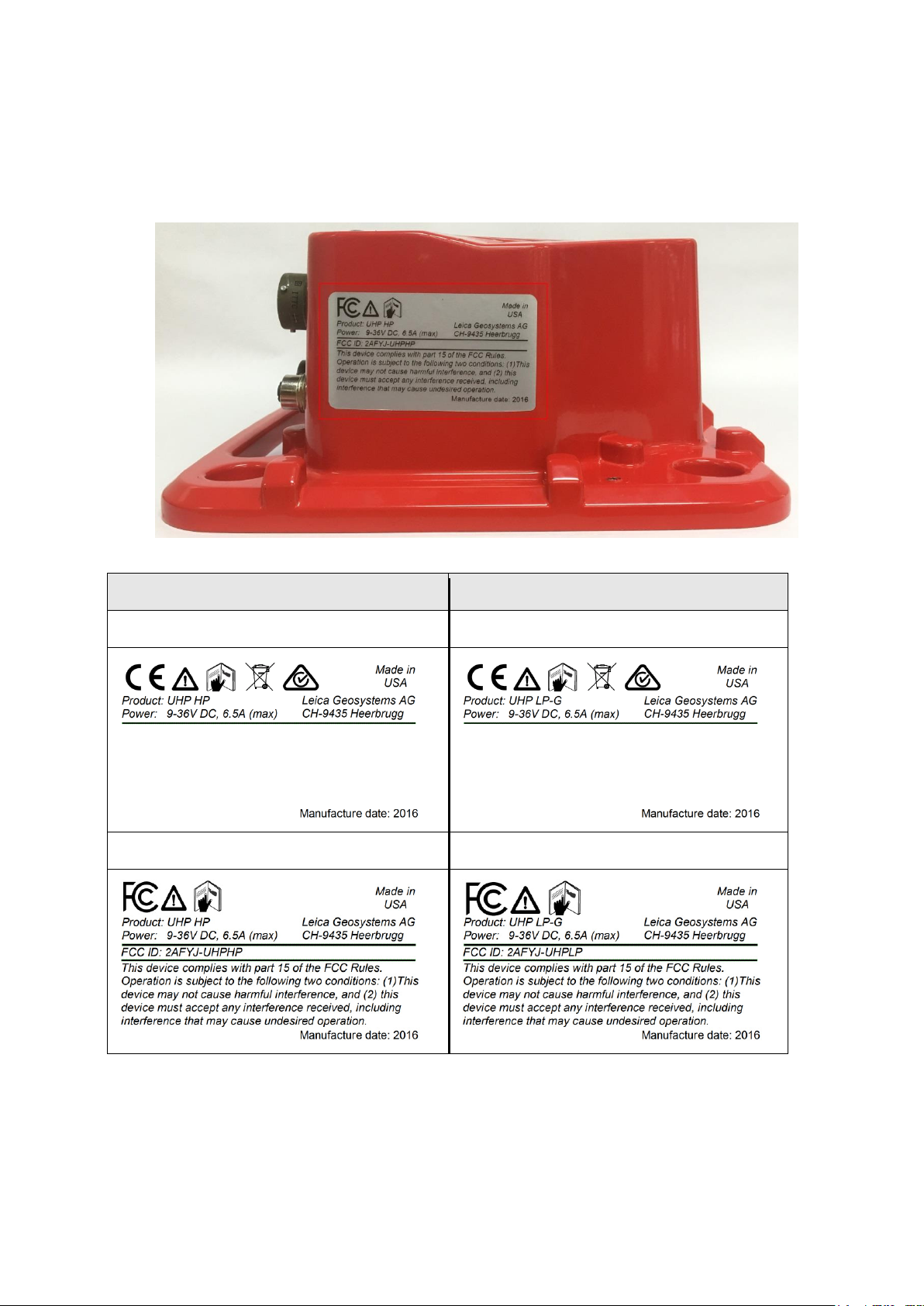
UHP Compliance Label - High Precision
UHP Compliance Label - Low Precision
Compliance Label – Europe/Australia
Compliance Label – Europe/Australia
FCC Compliance Label – U.S.A.
FCC Compliance Label – U.S.A.
2.5 Labels
2.5.1 Compliance Label Locations
Compliance labels are located on all UHP modules in the following location.
Typical Certification Label Location for all UHP
2.5.1.1 UHP Compliance Labels by Region
6 Commercial in Confidence © Leica Geosystems
Page 13
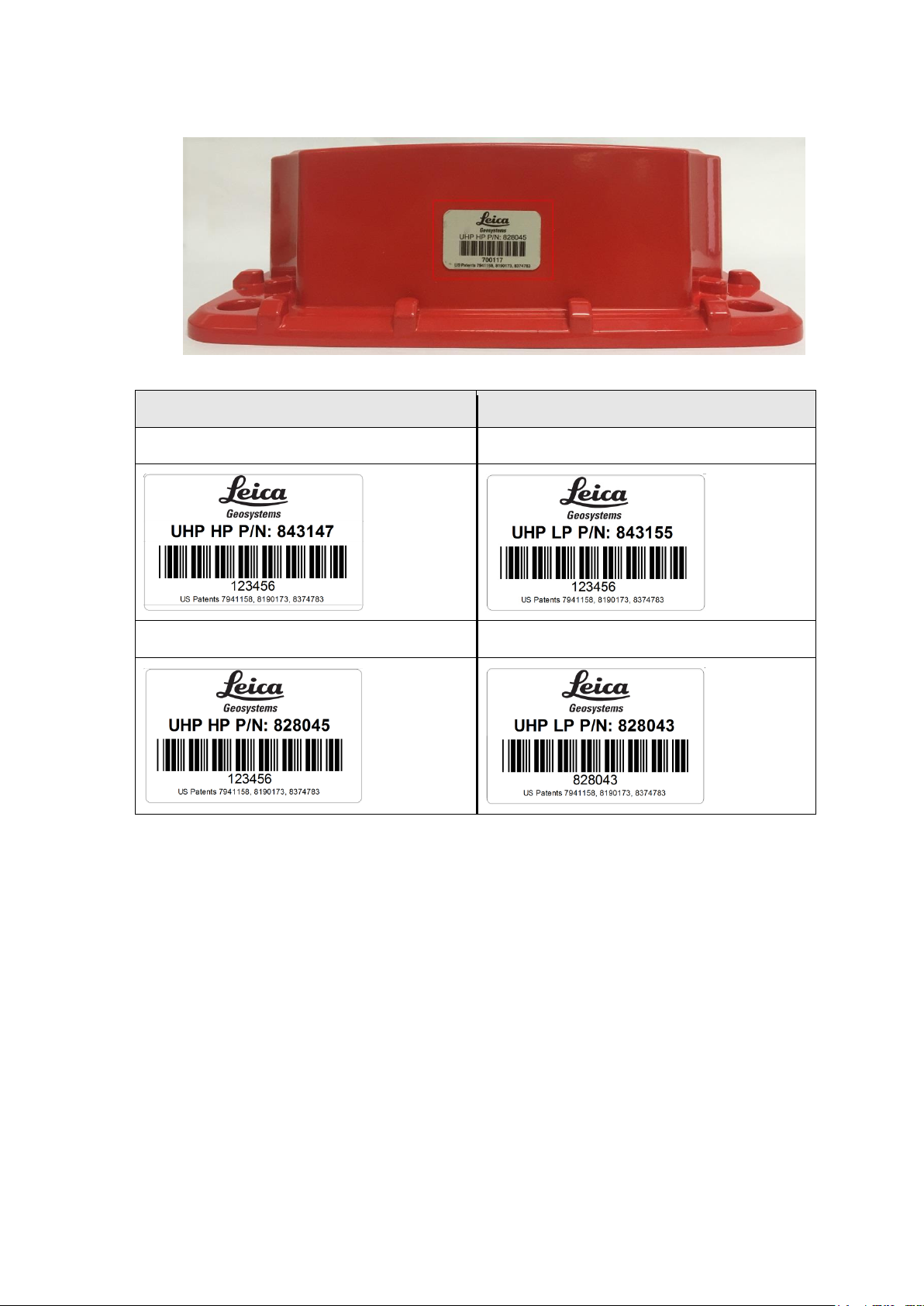
UHP Part Number Label - High Precision
UHP Part Number Label - Low Precision
Part Number Label – APAC Region
Part Number Label – APAC Region
Part Number Label – NAFTA Region
Part Number Label – NAFTA Region
2.5.2 UHP Part Number Label Location
2.5.2.1 UHP Part Number Labels by Region
Commercial in Confidence
© Leica Geosystems
7
Page 14
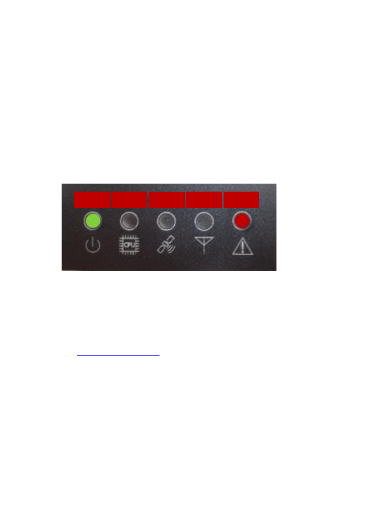
Power
CPU
GPS
Radio
Error
3 LED Overview
This section describes the statuses of the LEDs on the UHP modules. The information contained
in this guide is intended for high-end users and engineering staff.
The UHP is not designed to be opened in the field and it is impossible to debug faults if the single
board computer (SBC)/Display is not working. To overcome this issue LED status codes indicate
the status of the module by different LED flashing patterns for different error conditions
3.1 Light Emitting Diodes (LEDs)
The UHP has single color Red LED for Error and Green for all other LEDs. There are five external
LEDs on the UHP module:
Power (Green)
CPU (Green)
GPS (Green)
Radio (Green)
Error (Red)
The Power and the Error LEDs display the status of the RTK corrections:
3.2 Basic Operation
The LED codes are broken up into Status and Error codes, while a Status code is being
displayed, Error codes are inhibited.
3.2.1 Status Codes
Status codes are used to indicate where the module is functioning correctly but is not in the
normal operating mode. For example, in low power mode due to the battery voltage being low.
3.2.2 Error Codes
Error codes are stored in a list, and the module cycles through the list displaying the codes one at
a time. See
The LEDs in an error state flash a code to indicate the error.
When a code is displayed there is a pause, then the next error code displays until it loops
back to the start of the list.
The start of the error list is indicated by the Power LED turning red for two seconds on the
UHP.
Appendix C: LED Fault Codes for UHP error codes.
8 Commercial in Confidence © Leica Geosystems
Page 15

Status type
LED
Error (Red) Power (Green) CPU (Green) GPS (Green) Radio (Green)
All OK
OFF
ON
Ignition OFF
Alternates
between On
Green and Off,
with ½ second
delay
Network connected on
at least one interface
On Green
Connecting to network
on at least one interface
Flashing
Green
(Valid high-precision
GNSS solution for
multiple antennas; or
valid low-precision
solution for single
antenna.)
On Green
GNSS service active,
acquiring position
Flashing
Green
Main CPU ON
(Application launched)
On
Green
Operating system is
installing or has started.
Flashing
Green
3.3 Status Sources
The following are the reasons for the Status codes:
Ignition OFF
Critical Low Voltage
No Error
3.4 Error Sources
Various internal power supplies indicate reason for errors:
Input power supply (9-36V)
Critical low Voltage Detected
Internal power Rails (12V, 5V, 3.3V)
3.5 Status Codes
The status codes are displayed on the Power LED; if there is an active status condition the Error
Codes are inhibited.
3.6 UHP Status Code Chart
Commercial in Confidence
© Leica Geosystems
9
Page 16

4 Hardware Installation
4.1 Before Installation
Installation requires specialized knowledge and must be installed by a Leica Geosystems Mining
Authorized Installer. Leica Geosystems Mining recommends that installation of the UHP
equipment be performed by a qualified technician, as installation requires making electrical
connections.
CAUTION:
During any welding on the machine, the Leica Jigsaw UHP should be
completely isolated from the machine by disconnecting all of its cables
including power, I/O, and RF cables. Welding can cause large ground currents,
which may damage internal electronic components of the Leica Jigsaw UHP or
its antenna. The Leica Jigsaw UHP is not warranted for damage when
connected during welding activities.
4.1.1 Requirements
Install the system in a clean and dry workshop environment. Failure to do so may cause the
system to short or promote product malfunction.
Route and secure all cables and wiring to ensure that they do not rub, causing premature
failure.
The average installation time varies, but it should take approximately two to four hours per
vehicle to install the UHP. The time of installation may be more or less, based on vehicle type
and options purchased.
4.2 General UHP Installation
WARNINGS:
Do not mount the UHP where it may obscure the driver’s view of the road or
field.
Do not mount the UHP where it may be struck by a deploying airbag.
1. Select an appropriate place to mount the UHP.
2. Four mount holes are provided in the metal housing, these should be used to firmly mount the
UHP to the machine using the supplied vibration mounts.
4.2.1 Power Cable Installation
CAUTION:
The UHP is a 12-volt or 24-volt DC (negative-to-earth) system only. Connecting
to a positive-to-earth system will cause damage, which is not covered by
warranty.
1. Connect the supplied power cable to a reliable power source, for example, the vehicle’s main
power system:
a. Connect the red wire to a 12-volt or 24-volt positive source, capable of delivering a
constant 5 A.
b. Connect the black wire to the vehicle’s earth.
c. Optional: Connect the orange wire to the vehicles switched ignition power source to
automatically power the UHP on and off with the vehicle’s key.
2. Route and secure all cables and wiring to ensure that there is no rubbing, which can cause
premature failure.
3. Connect the power cable to the power connector on the front of the UHP.
10 Commercial in Confidence © Leica Geosystems
Page 17

UHP Type
Required Antenna : Leica Part Number
UHP LP and UHP HP
GNSS: 828463
Wi-Fi: 809870
4.2.2 Antenna Installation
4.2.2.1 Antenna Application
To ensure correct antenna application for mobile or fixed assets, refer to the Antenna Application
table.
Warning
Only antenna listed in the Antenna Application table are permitted to be used.
The UHP Wi-Fi antennas must be mounted more than 30cm away from the
operator.
Only antenna cables provided with the UHP equipment for installation as identified
in UHP installation diagrams in section 2 for the appropriate UHP variant are to be
used in UHP antenna installations.
Antenna Application
4.2.2.2 GNSS Antenna Installation
Note:
Read all instructions prior to assembly and installation.
The UHP GNSS Antenna should be mounted with a clear view of the sky and free from any
obstruction from machine components, and must meet the following criteria.
1. The UHP GNSS Antenna must be on the flat level part of the machine or mast.
2. Route the cables through the existing grommets if possible; if not, modification may be
required to route the cables to the desired location. If creating a new entry point, use a
grommet to protect the cables.
3. The cables must not be cut, kinked, or bent tightly, as performance degrades and a system
failure may result.
4. Cables should be routed neatly back to the UHP.
4.2.2.3 Wi-Fi Antenna Installation
Warning:
Antennas must be mounted more than 30 cm away from the human body.
Caution:
Antennas must be mounted more than 20 cm away from any other antenna.
Note:
Wi-Fi connectivity is dependent on network infrastructure which is outside the scope
of this UHP manual.
For UHP-LPG and UHP-HP communication is transmitted via Wi-Fi. The Wi-Fi antennas and
cabling for mounting the Wi-Fi communication antenna for UHP-LPG and UHP-HP variants with
two 2.4GHz antennas.
1. Route the cables through the existing grommets if possible; if not, modification may be
required to route the cables to the desired location. If creating a new entry point, use a
grommet to protect the cables.
2. The cables must not be cut, kinked, or bent tightly, as performance degrades and a system
failure may result.
Commercial in Confidence
© Leica Geosystems
11
Page 18

3. Cables should be routed neatly back to the UHP.
4. Wi-Fi Antennas can be mounted on either side of the vehicle to increase coverage and
visibility to local access points
5. Wi-Fi Antennas can be installed at a fixed offset of multiple 2.4GHz wavelengths for reasons
of diversity. This is recommended for vehicles such as Dozers where the antennas are
mounted on top of the vehicle with clear visibility to the sky.
4.2.2.4 External RTK Correction Antenna
For UHP-HP, RTK corrections are required. These can be delivered via Wi-Fi or alternatively via
an external RTK radio.
One RTK radio can be connected via an external communications port for example serial or
Ethernet.
An RTK radio should be mounted with good visibility to the RTK network infrastructure
4.2.3 Connection to Additional Sensors
For connection to all additional sensors and interfaces refer to machine specific installation
manuals.
4.2.4 Upgrade Software via USB Flash Drive
A new version of software may be installed from a USB Flash Drive.
CAUTION:
Do not turn off the UHP, or remove the USB Flash Drive while the software
upgrade is under way.
To upgrade the UHP software via USB Flash Drive, carry out the following steps:
1. Insert the compatible USB Flash Drive into the USB slot. The UHP restarts automatically
when the installation is complete.
2. Follow the prompts on the panel for panel calibration.
3. Remove the USB Flash Drive only when the unit is powered down.
12 Commercial in Confidence © Leica Geosystems
Page 19

5 Care and Transport
5.1 Transport
When transporting the product by rail, air, or sea, always use the complete original Leica
Geosystems Mining packaging, cardboard box, or an equivalent, in order to protect the product
against shock and vibration.
5.2 Storage
Ensure the temperature limits are followed when storing the equipment, particularly in summer if
the equipment is inside a vehicle. Please reference the Technical Data section for information
about temperature limits.
5.3 Cleaning and Drying
5.3.1 Product and Accessories
Use only clean, soft, lint-free cloth for cleaning. If necessary, moisten the cloth with water or pure
alcohol. Do not use other liquids; these may attack the polymer components.
5.3.2 Damp Products
Dry the product and the accessories at a temperature no greater than 40°C/104°F and clean
them. Do not repack until everything is completely dry.
5.3.3 Connectors and Plugs
Keep plugs clean and dry. Blow away any dirt lodged in the plugs of the connecting cables.
Commercial in Confidence
© Leica Geosystems
13
Page 20

6 Safety Directions
6.1 General Introduction
The following directions should enable the person responsible for the product, and the person
who actually uses the equipment, to anticipate and avoid operational hazards.
The person responsible for the product must ensure that all users understand these directions
and adhere to them.
6.2 Intended Use
6.2.1 Permitted Use
The UHP is intended for Mining use only.
Data communication with external appliances as part of a Leica Jigsaw Mining Solution.
6.2.2 Adverse Use
Adverse use can lead to injury, malfunction, and damage. It is the task of the person responsible
for the equipment to inform the user about hazards and how to counteract them. The product is
not to be operated until the user has been instructed how to work with it.
WARNING:
Unauthorized modification of Mining machinery by mounting or installing the
product may alter the function and safety of that mining machinery.
WARNING:
Follow the instructions of the machinery manufacturer. If no appropriate
instruction is available, ask the machinery manufacturer for instructions prior
to mounting or installing the product.
The following items result in adverse use:
Use of the product without instruction.
Use outside of the intended limits.
Disabling safety systems.
Removal of hazard notices.
Opening the product using tools, for example a screwdriver, unless this is specifically
permitted for certain functions.
Modification or conversion of the product.
Use after misappropriation.
Use of products with obviously recognizable damages or defects.
Use with accessories from other manufacturers without the prior explicit approval of Leica
Geosystems Mining.
Inadequate safeguards at the working site, for example when using on the intended site.
6.3 Limits of Use
6.3.1 Environment
Warning:
Not to be used on planes or any aircraft.
Warning:
Local safety authorities and safety experts must be contacted before working
in hazardous areas, or in close proximity to electrical installations or similar
situations by the person in charge of the product.
This product is suitable for use in an atmosphere appropriate for permanent human habitation.
6.4 Responsibilities
6.4.1 Manufacturer of the Product
Leica Geosystems Mining is responsible for supplying the product, including the User Manual and
original accessories, in a completely safe condition.
14 Commercial in Confidence © Leica Geosystems
Page 21

6.4.2 Manufacturers of Non-Leica Geosystems Mining Accessories
The manufacturers of non-Leica Geosystems Mining accessories for the product are responsible
for developing, implementing, and communicating safety concepts for their products, and are also
responsible for the effectiveness of those safety concepts in combination with the Leica
Geosystems Mining product.
6.4.3 Persons in Charge of the Product
WARNING:
The person responsible for the product must ensure that it is used in
accordance with the instructions. This person is also accountable for the
training and the deployment of personnel who use the product and for the
safety of the equipment in use.
The person in charge of the product has the following duties:
Understand the safety instructions on the product and the instruction in the User Manual.
Be familiar with local regulations relating to safety and accident prevention.
To ensure operators do not work within 30 cm of the Cellular or Wi-Fi antennas.
Inform Leica Geosystems Mining immediately if the product or the application becomes
unsafe.
6.5 Hazards of Use
6.5.1 General Hazards
The absence of instruction, or the inadequate imparting of instruction, can lead to incorrect or
adverse use, and can give rise to accidents with far-reaching human, material, financial, and
environmental consequences.
All users must follow the safety directions given by the manufacturer and the directions of the
person responsible for the product.
Only Leica Geosystems Mining authorized service workshops are entitled to repair these
products.
Inadequate securing of the working site can lead to dangerous situations, for example in
traffic, on building sites, and at industrial installations.
Always ensure that the working site is adequately secured. Adhere to the regulations
governing safety and accident prevention and road traffic.
The operator assures that the machine is operated, guided and monitored by a qualified user
(e.g., a licensed driver). The user has been able to take emergency measures, for example
an emergency stop.
While providing information to the operator of the machine, accidents may occur due to:
The operator not paying attention to the surroundings (persons, ditches, traffic,
etc.).
Malfunctions (of a system component interface, etc.).
6.5.2 Mechanical Hazards
Incorrect fastening of the equipment to vehicles or transporters poses the risk of the
equipment being broken by mechanical influence, vibration, or airstream. This may result in
accident and injury.
Periodically carry out test measurements and perform the field adjustments, particularly after
the product has been subjected to abnormal use and before and after important
measurements.
When setting up the product, ensure that the accessories are correctly adapted, fitted,
secured, and locked in position. Avoid subjecting the product to mechanical stress.
Commercial in Confidence
© Leica Geosystems
15
Page 22

Attach the external antenna professionally. The external antenna must be secured
additionally, for example by use of a safety cord. Ensure that the mounting device is correctly
attached and able to carry the weight of the external antenna (> 1kg) safely.
Deflect the mechanically moving machine components as far as possible and define a safe
installation zone.
If the accessories used with the product are not properly secured and the product is subjected
to mechanical shock, for example, by blows or falling objects, the product may be damaged or
people may sustain injury.
6.5.3 Lightning Hazards
WARNING:
If the product is used with accessories, for example, masts, staffs, or poles,
you may increase the risk of being struck by lightning. Danger from high
voltages also exists near power lines. Lighting, voltage peaks, or the touching
of power lines can cause damage, injury and death.
Be sure to remain at a safe distance from electrical installations. Do not use the product
directly under or in close proximity to power lines. If it is essential to work in such an
environment contact the safety authorities responsible for electrical installations and follow
their instructions.
To prevent damages due to indirect lightning strikes (voltage spikes) cables, for example for
antenna, power source or modem should be protected with appropriate protection elements,
like a lightning arrester. These instructions must be carried out by an authorized specialist.
If there is a risk of a thunderstorm, or if the equipment is to remain unused and unattended for
a long period, protect your product additionally by unplugging all systems components and
disconnecting all connecting cable and supply cables.
If the product is permanently mounted in an exposed location, it is advisable to provide a
lightning conductor for the product as detailed below. Always follow the regulations in force by
your country regarding grounding antennas and mast. These installations must be carried out
by an authorized specialist.
6.5.3.1 Lightning Conductors
Suggestion for design of a lightning conductor for a GNSS system:
6.5.3.1.1 On Non-Metallic Structures
On Non-Metallic Structures, protection by air terminals is recommended.
1. An air terminal is a pointed solid or tubular rod of conducting material with mounting and
connection to a conductor.
2. The position of four air terminals should be uniformly distributed around the antenna at a
distance equal to the height of the air terminal. The air terminal diameter should be 12mm for
copper or 15mm for aluminum. The height of the air terminals should be 25cm to 50cm.
3. All air terminals should be connected to the down conductors. The diameter of the air terminal
should be kept to a minimum to reduce GNSS signal shading.
6.5.3.1.2 On Metallic Structures
On Metallic Structures protection is as described for non-metallic structures, but the air terminals
can be connected directly to the conducting structure without the need for down conductors.
16 Commercial in Confidence © Leica Geosystems
Page 23

6.5.4 Disposal
If the product is improperly disposed of, the following can happen:
If polymer parts are burnt, poisonous gases are produced, which may impair health.
By disposing of the product irresponsibly, unauthorized persons may use it in contravention of
the regulations, exposing themselves and third parties to the risk of severe injury and
rendering the environment liable to contamination.
Caution:
The product must not be disposed of with household waste. Dispose of
the product appropriately in accordance with the national regulations in force
in your country.
Always prevent access to the product by unauthorized personnel. Product
Specific treatment and waste management information can be downloaded
from the Leica Geosystems home page at http://www.leicageosystems.com/treatment or obtained from your Leica Geosystems Mining
dealer.
6.6 Electromagnetic Compatibility (EMC)
The term Electromagnetic Compatibility is taken to mean the capability of the product to function
smoothly in an environment where electromagnetic radiation and electrostatic discharges are
present, and without causing electromagnetic disturbances to other equipment.
Electromagnetic radiation can cause disturbances in other equipment. Although the product
meets the strict regulations and standards that are enforced in this respect, Leica
Geosystems Mining cannot completely exclude the possibility that other equipment may be
disturbed.
There is risk that disturbances may be caused in other equipment if the product is used in
conjunction with accessories from other manufacturers, for example field computers, personal
computers, two-way radios, non-standard cables, or external batteries.
Use only the equipment and accessories recommended by Leica Geosystems Mining. When
combined with the product, they meet the strict requirements stipulated by the guidelines and
standards. When using computers and two-way radios, pay attention to the information about
electromagnetic compatibility provided by the manufacturer.
Disturbances caused by electromagnetic radiation can result in erroneous measurements.
Although the product meets the strict regulations and standards which are enforced in this
respect, Leica Geosystems Mining cannot completely exclude the possibility that the product
may be disturbed by very intense electromagnetic radiation produced by, for example, nearby
transmitters, two-way radios, or diesel generators.
Check the plausibility of results obtained under these conditions.
If the product is operated with connecting cables attached at only one of their two ends, the
permitted level of electromagnetic radiation may be exceeded and the correct functioning of
other products may be impaired.
While the product is in use, connecting cables must be connected at both ends.
Commercial in Confidence
© Leica Geosystems
17
Page 24
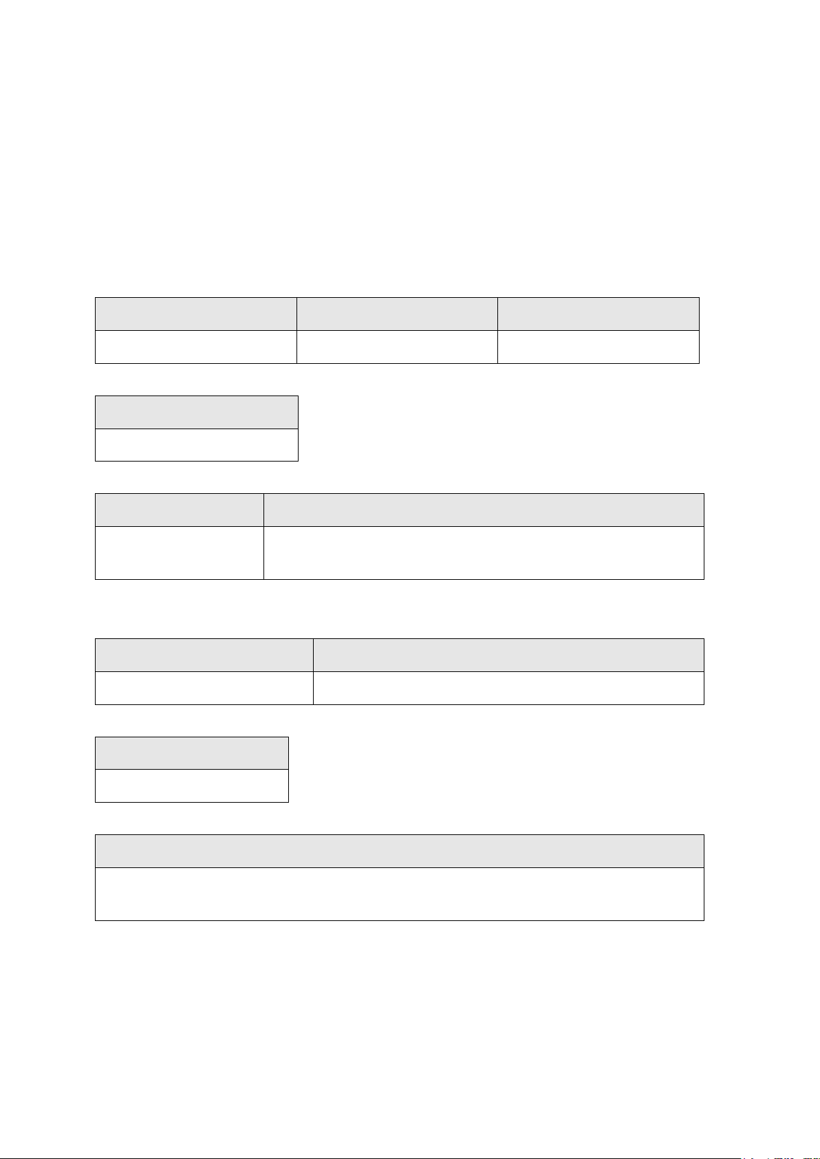
Length (cm)
Width (cm)
Height (cm)
32.3
22.8
9.9
Weight (kg)
3.811
Consumption (W)
External Supply Voltage
60 max
Normal Voltage 24V DC (-)
Voltage Range 9V – 36V
Operating Temperature (°C)
Storage Temperature (°C)
-40 to +60
-40 to +85
Protection
IP67
Protection
Up to 95%
The effects of condensation are effectively counteracted by periodically drying out the UHP-LPG.
7 Technical Data
7.1 UHP-LPG Technical Data
7.1.1 Design
Aluminum enclosure with a polymer top decal.
7.1.1.1 User Interface
Five LEDs.
VGA Screen interface with USB Touch Screen
7.1.1.2 Dimensions
7.1.1.3 Weight
7.1.1.4 Power
7.1.2 Environmental Specifications
7.1.2.1 Temperature
7.1.2.2 Protection Against Water, Dust, and Sand
7.1.2.3 Humidity
7.1.3 Interfaces
RS232 Serial: 5x
CAN: 2x
Ethernet: 3x
USB: 3x (1 Type A)
VGA: 1x
18 Commercial in Confidence © Leica Geosystems
Page 25

Field
Description
Manufacturer
NovAtel
Model
OEMStar®
Signal Tracking
L1 GPS, L1 GLONASS
Channel Count
14
Channel Configuration
Any combination of GPS L1 & GLONASS L1
Horizontal Position Accuracy1(See below)
Single Point L1: 1.5m RMS
Field
Description
Manufacturer
Antcom
Model
G3
Frequency
L1, 1528.5 – 1616 MHz
Power Out 12V: 6x
Digital Inputs: 5x
Digital Outputs: 2x
Frequency Input: 1x
Ignition Input 1x
Audio Output: 1x
GNSS RF Input 1x
Wi-Fi Input/Output 1x
7.1.4 GNSS Technical Data
7.1.4.1 GNSS Receiver
1
Accuracy is dependent upon various factors including:
Number of satellites tracked
Constellation geometry
Observation time
Ephemeris accuracy
Ionospheric disturbance
Multipath and resolved ambiguities
7.1.4.2 GNSS Antenna
7.1.5 Wi-Fi
The UHP-LPG variant has the following Wi-Fi component.
2.4GHz radio b/g/n compliant
Americas: Avg. TX Power 24dBm, +/- 2dB
Australia and EMEA: Avg. TX Power 23dBm +/- 2dB
Commercial in Confidence
© Leica Geosystems
19
Page 26

Length (cm)
Width (cm)
Height (cm)
32.3
22.8
9.9
Weight (kg)
3.811
Consumption (W)
External Supply Voltage
60 max
Normal Voltage 24V DC (-)
Voltage Range 9V – 36V
7.1.6 FCC Statement (Applicable for U.S.)
This equipment has been tested and found to comply with the limits for a Class A digital device,
pursuant to Part 15 of the FCC Rules. These limits are designed to provide reasonable protection
against harmful interference when the equipment is operated in a commercial environment. This
equipment generates, uses, and can radiate radio frequency energy and, if not installed and used
in accordance with the instruction manual, may cause harmful interference to radio
communications. Operation of this equipment in a residential area is likely to cause harmful
interference, in which case the user will be required to correct the interference at their own
expense.
This equipment generates, uses and can radiate frequency energy and, if not installed and used
in accordance with the instructions, may cause harmful interference to radio communication.
However, there is no guarantee that interference will not occur in a particular installation. If this
equipment does cause harmful interference to radio or television reception, which can be
determined by turning the equipment off and on, the user is encouraged to try to correct the
interference by one or more of the following measures:
Reorient or relocate the receiving antenna.
Increase the separation between the equipment and the receiver.
Connect the equipment into an outlet on a circuit different from that to which the receiver is
connected.
Consult the dealer or an experienced radio/TV technician for help.
Changes or modifications not expressly approved by Leica Geosystems for compliance could void
the user's authority to operate the equipment.
7.2 UHP-HP Technical Data
7.2.1 Design
Aluminum enclosure with a polymer top decal.
7.2.1.1 User Interface
Five LEDs.
VGA Screen interface with USB Touch Screen
7.2.1.2 Dimensions
7.2.1.3 Weight
7.2.1.4 Power
20 Commercial in Confidence © Leica Geosystems
Page 27

Operating Temperature (°C)
Storage Temperature (°C)
-40 to +60
-40 to +85
Protection
IP67
Protection
Up to 95%
The effects of condensation are effectively counteracted by periodically drying out the UHP-HP.
7.2.2 Environmental Specifications
7.2.2.1 Temperature
7.2.2.2 Protection Against Water, Dust, and Sand
7.2.2.3 Humidity
7.2.3 Interfaces
RS232 Serial: 5x
CAN: 2x
Ethernet: 3x
USB: 3x (1 Type A)
VGA: 1x
Power Out 12V: 6x
Digital Inputs: 6x
Digital Outputs: 2x
Frequency Input: 1x
Ignition Input: 1x
Audio Output: 1x
GNSS RF Input: 2x
Wi-Fi Input/Output 1x
Commercial in Confidence
© Leica Geosystems
21
Page 28

Field
Description
Manufacturer
NovAtel
Model
OEM628™
Signal Tracking
GPS: L1, L2, L2C, L5
GLONASS: L1, L2
2
BeiDou: B1, B2
Galileo: E1, E5a, E5b, AltBOC
Channel Count
120
Position Accuracy 1(See below)
Single Point L1/L2: 1.2m RMS
RT-2®: 10mm + 1ppm Horizonal, 20mm + 1ppm Vertical
Field
Description
Manufacturer
Antcom
Model
G5
Frequency
L1/L2/L2C/L5 GPS, L1/L2 GLONASS, B1/B2
BeiDou, E1/E5a/E5b/AltBOC Galileo 1528.5 –
1616 MHz
7.2.4 GNSS Technical Data
7.2.4.1 GNSS Receiver
1
Accuracy is dependent upon various factors including:
Number of satellites tracked
Constellation geometry
Observation time
Ephemeris accuracy
Ionospheric disturbance
Multipath and resolved ambiguities
2
The hardware is designed to support the BeiDou satellite system. However a future
software upgrade is required.
7.2.4.2 GNSS Antennas
7.2.5 Wi-Fi
The UHP-HP variant has the following Wi-Fi component.
2.4GHz radio b/g/n compliant
Americas: Avg. TX Power 24dBm, +/- 2dB
Australia and EMEA: Avg. TX Power 23dBm +/- 2dB
22 Commercial in Confidence © Leica Geosystems
Page 29

7.2.6 FCC Statement (Applicable for U.S.)
This equipment has been tested and found to comply with the limits for a Class A digital device,
pursuant to Part 15 of the FCC Rules. These limits are designed to provide reasonable protection
against harmful interference when the equipment is operated in a commercial environment. This
equipment generates, uses, and can radiate radio frequency energy and, if not installed and used
in accordance with the instruction manual, may cause harmful interference to radio
communications. Operation of this equipment in a residential area is likely to cause harmful
interference, in which case the user will be required to correct the interference at their own
expense.
This equipment generates, uses, and can radiate frequency energy and, if not installed and used
in accordance with the instructions, may cause harmful interference to radio communication.
However, there is no guarantee that interference will not occur in a particular installation. If this
equipment does cause harmful interference to radio or television reception, which can be
determined by turning the equipment off and on, the user is encouraged to try to correct the
interference by one or more of the following measures:
Reorient or relocate the receiving antenna.
Increase the separation between the equipment and the receiver.
Connect the equipment into an outlet on a circuit different from that to which the receiver is
connected.
Consult the dealer or an experienced radio/TV technician for help.
Changes or modifications not expressly approved by Leica Geosystems for compliance could void
the user's authority to operate the equipment.
Commercial in Confidence
© Leica Geosystems
23
Page 30

8 Appendix A: Copyright
This software contains copyrighted software, which is licensed under various open source
licenses. Contact [email protected].
For some of the open source modules, corresponding source code can be obtained from Leica
Geosystems Mining’s open source center located at opensource.leica-geosystems.com/
24 Commercial in Confidence © Leica Geosystems
Page 31
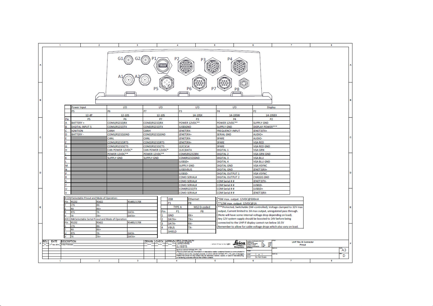
9 Appendix B: UHP Connector Pin Out
Commercial in Confidence
© Leica Geosystems
25
Page 32
Error type
LED
Error (Red) Power (Green)
Fast Current Trip
Port 2 12V
2 Red
2 Green
Port 3 12V
2 Red
3 Green
Port 4 12V
2 Red
4 Green
Port 6 CAN
2 Red
5 Green
Port 6 12V
2 Red
6 Green
Port 7 CAN
2 Red
7 Green
Port 7 12V
2 Red
8 Green
Input Voltage
Battery Voltage Critically Low <9V
4 Red
1 Green
Green
Power
Light
Red
Error
Light
10 Appendix C: LED Fault Codes
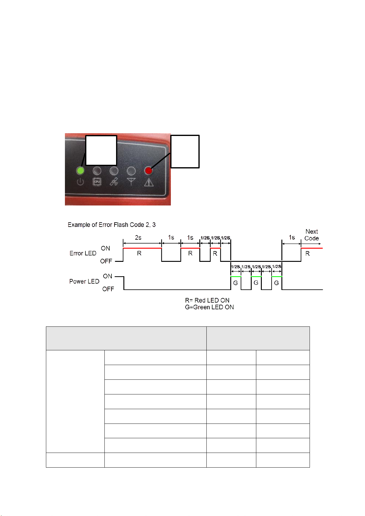
Faults detected are logged in the system log as well as flashed on the UHP LEDs.
The UHP indicates fault codes by flashing or blinking two of the UHP status LEDs. The fault
code, red and green, is indicated by two blinking LEDs. The power LED for green and the error
LED for red. To indicate the start of the fault code, the red error LED is blinked on one long
duration (two seconds), followed by the remainder of the error code as follows: the red error LED
blinked a number of times (Red) short duration, followed by green power LED blinked a number
of times (Green) a number of times short duration. Please see the Fault Code table for error
codes.
Power (Green) and Error (Red) UHP Lights used for Error Codes
Sample Error Code Display Time
Fault Code Error Table
26 Commercial in Confidence © Leica Geosystems
Page 33

Error type
LED
Error (Red) Power (Green)
(only Rev B and above)
Battery Voltage Low <11V (only
Rev B and above)
4 Red
2 Green
Battery Voltage High >32V (only
Rev B and above)
4 Red
3 Green
Power Fault (override low voltage)
4 Red
4 Green
Power not ok (override low
voltage)
4 Red
5 Green
Power current high
4 Red
6 Green
Power consumption high
4 Red
7 Green
Power consumption critical
4 Red
8 Green
Internal Voltage
Regulation
12V fail
5 Red
3 Green
5V fail
5 Red
4 Green
3.3V fail
5 Red
5 Green
SBC (no coms for
30sec)
Not talking to backplane
6 Red
1 Green
Internal Error
Over or Under Temp
6 Red
5 Green
Commercial in Confidence
© Leica Geosystems
27
Page 34

11 Appendix D: UHP FCC Maximum Personal
Exposure (MPE) Calculations
Reference: FCC document ‘Evaluating Compliance with FCC Guidelines for Human Exposure to
Radiofrequency Electromagnetic Fields ‘
From herein this document will be referred to as the ‘FCC Guidline to MPE‘ document.
11.1 UHP Intentional Radiators
The UHP comprises the following RF interfaces
11.1.1 Wi-Fi
Radio : Ubiquiti Networks SR71 802.11n MIMI mini-PCI Module
Antenna: MobileMark OD6-2400MOD2-BLK-SP-35.
Refer documents ‘SR71a_datasheet.pdf’, ‘antenna-spec-140-od-2400.pdf’ and ‘OD6-2400pat.pdf’ for further information.
11.2 MPE Calculations
11.2.1 MPE Formula
The FCC Guide to MPE document section 3 ‘Methods of Predicting Human Exposure’ page 17,
advises to use the following formula
S = P. G / 4.π.R2
R = ( P.G / 4.π.S )
Where
S = Power Density (MPE) mW/cm2
P = Power input to antenna (power output from radio) (mW)
G = Power gain of antenna relative to isotropic radiator (dBi)
R = Distance from antenna (cm)
0.5
11.2.2 Wi-Fi MPE Calculations
Referring to The FCC Guide to MPE document, Appendix A, Table 1 (B) Limits for General
Population/Uncontrolled exposure (1.5GHz to 100GHz).
S = 1.0 mW/cm2
P = 24dB = 251.2mW (ref SR71 data sheet)
G = 6dBi (ref RFI CD2405 data sheet)
R = ( P.G / 4.π.S )
R = ( 251.2 x 6 / 4. π. 1)
R = 11 cm
0.5
0.5
28 Commercial in Confidence © Leica Geosystems
Page 35

Term
Definition
Ephemeris
A list of positions or locations of a celestial object as a function of
time.
GNSS
Global Navigation Satellite Systems
GPS
GPS is the shortened term for NAVSTAR GPS, which stands for
Navigation System with Time And Ranging Global Positioning
System.
Ionospheric
Upper part of earth’s atmosphere at 53 to 370 miles.
LED
Light-emitting Diode
RTK
RTK (Real Time Kinematic) A term used to describe the procedure of
resolving the phase ambiguity at the GPS receiver, so that the need
for post-processing is removed.
SBAS
SBAS (Satellite Based Augmentation System) SBAS comprises of a
number of ground stations at surveyed points. The ground stations
take measurements of GPS satellites, their signals, and
environmental factors, which may affect the signals received by
users, and create adjustment messages to send to one or more
satellites for broadcast to users.
SBC
Single Board Computer
UHP
Universal Hardware Platform
12 Glossary
Commercial in Confidence
© Leica Geosystems
29
Page 36

United States, Canada
& Mexico
Leica Geosystems
Mining
Tucson, USA
Ph: +1 520 529 8729
Latin America
Leica Geosystems
Santiago, Chile
Ph: +56 22 224 8421
Australia & South-East
Asia
Leica Geosystems
Brisbane, Australia
Ph: +61 7 3117 8900
Africa
Leica Geosystems
Johannesburg,
South Africa
Ph: +27 11 594 3900
China
Leica Geosystems
Beijing, China
Ph: +86 10 8569 1819
India
Leica Geosystems
Gurgaon, India
Ph: +91 124 412 2222
Indonesia
PT Leica Geosystems
Balikpapan, Indonesia
Ph: +62 811 544 1258
Hexagon Mining is the only company to solve surface and underground
challenges with proven technologies for planning, operations, and safety.
We bring surveying, design, fleet management, production optimization,
and collision avoidance together in a life-of-mine solution that connects
people and processes. Our customers are safer, more productive, and
can make sense of their data.
Headquartered in Tucson, Arizona, with offices worldwide, Hexagon
Mining is shaping smart change by helping to connect all parts of a mine
with technologies that make sense of data in real time. We deliver
technology, service, and support. Learn more at hexagonmining.com and
follow us @HexagonMining.
Mining is part of Hexagon (Nasdaq Stockholm: HEXA B; hexagon.com), a
leading global provider of information technologies that drive quality and
productivity across geospatial and industrial enterprise applications.
Our Locations
*Additional regional support centers are listed on the website
 Loading...