

Page 1
RDS
USER MANUAL
Version 5.0.0
Page 2

Contents
H000002007-RDS User Manual │Version 5.0.0 (2018-09-17) │1
RDS
User Manual
Information, support:
www.HexagonMI.com
Page 3
Contents
H000002007-RDS User Manual │Version 5.0.0 (2018-09-17) │2
CONTENTS
A.1 What is RDS ................................................................................................................... 9
A.2 RDS Levels and securities ............................................................................................. 9
A.3 System Requirements .................................................................................................. 10
A.4 Compatibilities .............................................................................................................. 12
A.5 SMART Data Exchange (arms only) ............................................................................ 15
A.5.1 What is SMART ............................................................................................... 15
A.5.2 What type of information does Hexagon Manufacturing Intelligence collect? . 16
A.5.3 How does Hexagon Manufacturing Intelligence use collected information? ... 17
A.5.4 Privacy protection ............................................................................................ 17
A.5.5 Deactivation ..................................................................................................... 17
A.5.6 Further information........................................................................................... 17
A.6 Installation .................................................................................................................... 18
A.7 Quick Reference ........................................................................................................... 21
C.1 System status ............................................................................................................... 25
C.1.1 Global status .................................................................................................... 25
C.1.2 System status .................................................................................................. 26
C.1.3 Status details ................................................................................................... 27
C.2 Bluetooth ...................................................................................................................... 29
C.2.1 Connect a new device ..................................................................................... 30
C.3 Shortcuts ...................................................................................................................... 31
C.4 Scan view ..................................................................................................................... 32
C.4.1 Description ....................................................................................................... 32
C.4.2 Minimum / Extended Window .......................................................................... 32
C.5 Quick Access Menu (Arms only) .................................................................................. 33
C.5.1 Control the Q.A.M. ........................................................................................... 34
C.5.2 Available actions .............................................................................................. 36
D.1 Summary ...................................................................................................................... 39
D.1.1 Summary (arm) ................................................................................................ 39
D.1.2 Summary (tracker) ........................................................................................... 40
D.2 Connection ................................................................................................................... 41
D.2.1 USB connection (arm) ..................................................................................... 42
D.2.2 WLAN Settings (arm) ....................................................................................... 43
D.2.3 Computer setup for wireless connection (arm) ................................................ 46
D.2.4 Wireless connection (arm) ............................................................................... 48
D.2.5 RSx wireless connection (arm) ........................................................................ 50
D.2.6 Wired Ethernet connection (arm / tracker)....................................................... 51
D.3 General parameters ..................................................................................................... 53
D.3.1 Language ......................................................................................................... 53
D.3.2 Head light (for equipped arms) ........................................................................ 54
D.4 SMART (arms) ............................................................................................................. 55
D.5 Measurement profiles (arms) ....................................................................................... 56
D.6 Probe (arms) ................................................................................................................ 57
D.6.1 Probe list and selection ................................................................................... 58
D.6.2 View selected probe (advanced user) ............................................................. 59
D.6.3 Adding a new probe ......................................................................................... 61
D.6.4 Non-repeatable probes (Absolute 71 series) ................................................... 62
Page 4
Contents
H000002007-RDS User Manual │Version 5.0.0 (2018-09-17) │3
D.7 Scanner ........................................................................................................................ 64
D.7.1 Common items ................................................................................................. 65
D.7.2 Scanning profiles ............................................................................................. 66
D.7.3 Sampling filter (HP-L-20.8 / CMS108 / RS3-5 / LAS / LAS-XL) ...................... 69
D.7.4 Exposure (HP-L-8.9 / RS2-5) .......................................................................... 70
D.7.5 Scanning modes (HP-L-20.8 / CMS108 / LAS, LAS-XL)................................. 72
D.7.6 Gain – Quality filter (HP-L-20.8 / CMS108 / LAS / LAS-XL) ............................ 73
D.8 Auxiliary Referencing (arms) ........................................................................................ 74
D.8.1 Reminder: Theory about moving a measurement device ................................ 75
D.8.2 Description of the Reference Tab .................................................................... 76
D.8.3 Leapfrog in RDS .............................................................................................. 78
D.8.4 GridLOK / SpaceLOK ...................................................................................... 79
D.9 Advanced settings (arms)............................................................................................. 82
D.10 Video capture (for equipped arms) ......................................................................... 84
D.11 Access Control (advanced user) ............................................................................ 87
D.11.1 How to … modify the protection of a function ................................................ 87
D.12 Features (arms) ...................................................................................................... 88
D.12.1 Interface ......................................................................................................... 88
D.12.2 How to add a new feature (Advanced User) ................................................. 89
D.12.3 Types of feature ............................................................................................. 90
D.13 About ....................................................................................................................... 91
E.1 Find a target - OVC ...................................................................................................... 93
E.1.1 Description ....................................................................................................... 93
E.1.2 How to find and lock a target ........................................................................... 94
E.2 Select a target .............................................................................................................. 95
E.3 Settings......................................................................................................................... 96
E.4 Measure with the tracker .............................................................................................. 98
F.1 Presentation ................................................................................................................. 99
F.2 RDS Toolbox description............................................................................................ 102
F.2.1 Main panel description ................................................................................... 102
F.2.2 Menus navigation ........................................................................................... 103
F.2.3 RDS Toolbox notifications .............................................................................. 105
F.2.4 Local and Distant arms .................................................................................. 107
F.2.5 Maintenance Connection ............................................................................... 107
F.3 Panels common features............................................................................................ 108
F.3.1 Status of the connection ................................................................................ 108
F.3.2 Arm selection ................................................................................................. 109
F.3.3 Spreadsheets management – Search (Ctrl+F) .............................................. 110
G.1 News & links publications ........................................................................................... 112
H.1.1 Standard information ..................................................................................... 115
H.1.2 Arm properties (deploy) ................................................................................. 117
I.1 Vault screen description ............................................................................................. 119
I.2 Types of packages ..................................................................................................... 121
I.3 Status and information of a package .......................................................................... 123
I.3.1 Action status .................................................................................................... 123
I.3.2 Information of the package .............................................................................. 124
I.4 Create and synchronize a Package ........................................................................... 125
I.4.1 Manual backup ................................................................................................ 125
I.4.2 Other automatic packages .............................................................................. 126
I.4.3 Comment ......................................................................................................... 126
I.4.4 Synchronization ............................................................................................... 127
I.5 Download a Package from HEXAGON SERVER ...................................................... 128
I.5.1 Listed Arms - refresh ....................................................................................... 128
Page 5
Contents
H000002007-RDS User Manual │Version 5.0.0 (2018-09-17) │4
I.5.2 Download a package ....................................................................................... 129
I.6 Use a Package ........................................................................................................... 130
I.6.1 Display the information – get the package ...................................................... 131
I.6.2 Restore the Armdata ....................................................................................... 132
I.6.3 Switch to SMART dataset ............................................................................... 132
I.7 Remove a package / an arm ...................................................................................... 133
I.8 SMART Dataset manual Upload ................................................................................ 134
I.8.1 Manual upload of SMART Dataset .................................................................. 134
I.8.2 Dump SMART Dataset .................................................................................... 135
I.8.3 Open a SMART Dataset ................................................................................. 135
I.9 Quick vault guide ........................................................................................................ 136
I.9.1 How to … find a package ................................................................................ 136
I.9.2 How to … get a package file ........................................................................... 137
I.9.3 How to … save the Arm data .......................................................................... 138
I.9.4 How to … restore the Armdata ........................................................................ 139
J.1 Presentation ............................................................................................................... 140
J.2 Communication with the HEXAGON Server .............................................................. 141
J.3 Arm selection: 2 possibilities ...................................................................................... 141
J.3.1 Local arm - Standard mode ............................................................................ 141
J.3.2 Local and Distant arm - Database mode ........................................................ 142
J.4 SMART Overview panel ............................................................................................. 143
J.4.1 SMART components graphic view ................................................................. 144
J.4.2 SMART Overview components description .................................................... 145
J.5 Alerts .......................................................................................................................... 146
J.5.1 Alert notifications ............................................................................................ 147
J.5.2 SMART Alerts panel ....................................................................................... 148
J.5.3 Alert details ..................................................................................................... 149
J.6 Analyse Indicators ...................................................................................................... 150
J.6.1 Description of the panel .................................................................................. 151
J.6.2 Use a template ............................................................................................... 152
J.6.3 Select an indicator .......................................................................................... 153
J.6.4 Details of an indicator ..................................................................................... 154
J.6.5 Type of charts ................................................................................................. 156
J.6.6 Period time (counters only) ............................................................................ 157
J.6.7 Add an indicator to a chart ............................................................................. 158
J.6.8 Display a graph – details ................................................................................ 159
J.6.9 Export the values ............................................................................................ 163
J.7 Quick SMART guide ................................................................................................... 164
J.7.1 Quick display: Use a template ........................................................................ 164
J.7.2 How to add an indicator diagram to a graph .................................................. 165
K.1 Program a probe ........................................................................................................ 167
K.1.1 Probe details .................................................................................................. 168
K.1.2 Find a probe ................................................................................................... 169
K.1.3 How to … program a probe ........................................................................... 170
K.2 Configure Wi-Fi Chipset ............................................................................................. 171
K.2.1 Process .......................................................................................................... 172
K.3 Upgrade firmware ....................................................................................................... 173
K.3.1 Check the versions of the firmware ............................................................... 174
K.3.2 Upgrade the firmware (Arm & Pack) .............................................................. 175
K.3.3 Upgrade the RSx scanner (option) ................................................................ 176
K.4 View logs .................................................................................................................... 178
L.1 How to do a quick measure ........................................................................................ 180
L.1.1 Description of the measurement window ....................................................... 180
L.1.2 Measurement procedure ................................................................................ 181
L.2 Available features ....................................................................................................... 182
L.2.1 Dimensions ..................................................................................................... 182
L.2.2 Distances ........................................................................................................ 182
L.2.3 Angles ............................................................................................................ 183
Page 6

Contents
H000002007-RDS User Manual │Version 5.0.0 (2018-09-17) │5
M.1 Configuration for end-software ................................................................................... 184
M.1.1 Pc-Dmis ......................................................................................................... 186
M.1.2 TubeShaper ................................................................................................... 186
M.1.3 3DReshaper .................................................................................................. 186
M.1.4 Spatial Analyzer ............................................................................................ 187
M.1.5 Quindos7 ....................................................................................................... 187
M.1.6 Romosoft (GPad / GTube) ............................................................................ 188
M.1.7 Docs .............................................................................................................. 188
M.1.8 PolyWorks ..................................................................................................... 189
M.1.9 Verisurf .......................................................................................................... 191
M.1.10 PowerINSPECT ........................................................................................... 194
M.1.11 PowerSHAPE .............................................................................................. 195
M.1.12 Metrolog / µLog ........................................................................................... 196
M.1.13 Geomagic .................................................................................................... 198
M.1.14 Aberlink ....................................................................................................... 199
M.1.15 Calypso ....................................................................................................... 203
M.1.16 Rhinoceros .................................................................................................. 204
M.2 TCP Ports ................................................................................................................... 205
M.3 Troubleshooting .......................................................................................................... 206
Page 7

INTRODUCTION
H000002007-RDS User Manual │Version 5.0.0 (2018-09-17) │6
INTRODUCTION
Dear customer, thank you for purchasing a product from Hexagon Manufacturing Intelligence. Before
starting any operation with your new HEXAGON® 3D measuring arm, please read these instructions.
This guide describes best practices for installing, configuring, and using your portable measuring arm.
For any other device or option not described in this manual please refer to other HEXAGON® products
manuals (e.g. RDS Data Collector, Absolute Arm…) available on the provided media.
For further information, please contact your local Hexagon Manufacturing Intelligence agent.
TRADEMARK NOTE
© Copyright 2018 Hexagon Manufacturing Intelligence. All rights reserved. Hexagon Manufacturing
Intelligence is part of Hexagon.
HEXAGON® and ABSOLUTE ARM™ are trademarks of HEXAGON AB.
Windows®, Windows Xp®, Windows Vista®, Windows7® and Windows10® are trademarks of Microsoft Inc.
Wi-Fi® and the Wi-Fi logo are trademarks of Wi-Fi Alliance.
The Bluetooth® word mark and logos are registered trademarks owned by the Bluetooth SIG, Inc. and any
use of such marks by Hexagon Manufacturing Intelligence is under license.
Other brands and product names are trademarks of their respective owners.
IMPORTANT NOTE
All information contained in this document is subject to be modified without any notification and does not
represent any engagement from HEXAGON AB. The software described in this manual is furnished under
licence agreement and must be used only in conformity with the terms of this licence. No part of this manual
may be reproduced or transmitted under any form or by any way, electronic or mechanical, including
photocopy or recording, for any purpose without Hexagon AB formal authorisation.
© HEXAGON MANUFACTURING INTELLIGENCE
DISCLAIMER NOTE
All non-authorised modification, repair or bad use of the HEXAGON® system will automatically void the
original manufacturer’s guaranty. The manufacturer is not responsible for damages to the software or
hardware caused by unauthorised handling, or use, of this material. For information regarding the warranty,
repair, technical assistance, latest updates and current information prices, please contact your local
Hexagon Manufacturing Intelligence agent.
Page 8
INTRODUCTION
H000002007-RDS User Manual │Version 5.0.0 (2018-09-17) │7
Conventions used in this guide
This manual uses the following conventions to alert you to information that varies from optional to critical in
nature. These guidelines are used to distinguish the difference between these passages:
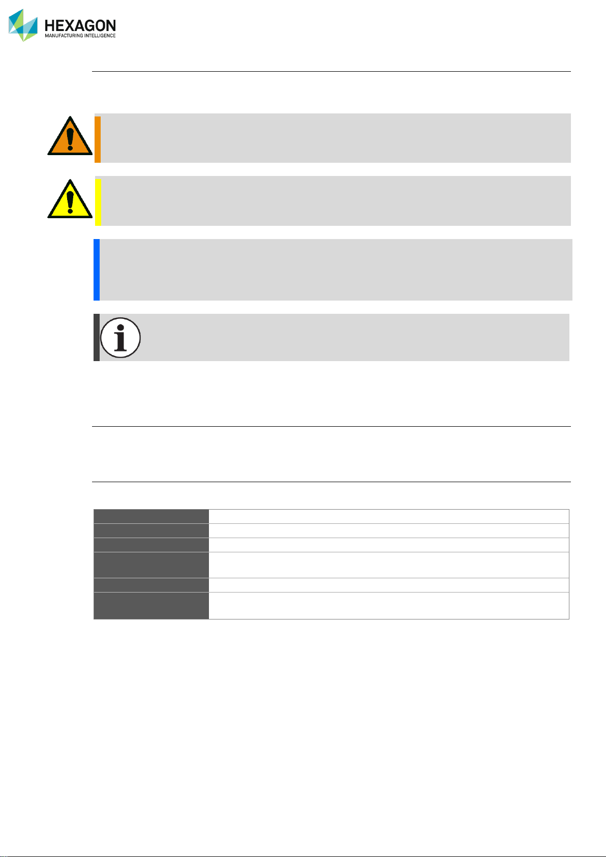
WARNING
A Warning indicates a hazardous situation, which, if not avoided, could result in death or serious
injury.
CAUTION
A Caution, used with the safety alert symbol, indicates a hazardous situation which, if not avoided,
could result in minor or moderate injury.
NOTICE
A Notice indicates useful advice about operation of your HEXAGON® system or its sub-parts.
Information contained in a Notice is not safety related. Failing to heed this advice may result in damage
to your HEXAGON® system or in inaccurate measurements.
Information indicates general advice or links to relevant documentation.
Moreover, the present document mostly respects the following international standard: ISO 8601 (format of
the dates),
Pictures in the manual
Pictures presented in this manual are not contractual, especially regarding the colours that may change
depending on the arm version or type.
Complete documentation
or more detailed information, please read complete manuals:
Arm
Absolute Arm user manual
Tracker
Absolute Tracker AT960 user manual
RDS
RDS manuals (RDS Data Collector, RDS What’s New)
Maintenance
Technicians manuals (Absolute Arm Technician, RDS Technician, RDS DC
Technician)
Accessories
Accessory guide
Application software
Software user manual (TubeShaper, Romosoft, GPad, GTube, DOCS,
Pc-Dmis, Pc-DmisTouch, 3DReshaper, Quindos, Spatial Analyzer…)
Page 9
IMPORTANT NOTE
H000002007-RDS User Manual │Version 5.0.0 (2018-09-17) │8
IMPORTANT NOTE
The following directions should enable the person responsible for the product, and the person who actually
uses the equipment, to anticipate and avoid operational hazards.
The person responsible for the product must ensure that all users understand these directions and adhere
to them.
NOTICE
Incorrect use can lead to equipment malfunction and/or damage. The person responsible for the product
should inform the user about hazards and how to counteract them. The software should not be operated
until the user has been instructed on correct use.
Responsibilities
Manufacturer of the product
Hexagon Manufacturing Intelligence, is responsible for supplying the product, including the
user manual and original accessories, in a complete and safe condition.
Manufacturer of non-HEXAGON® accessories
The manufacturer of non-HEXAGON® accessories for the product is responsible for
developing, implementing and communicating safety concepts for their products, and is also
responsible for the effectiveness of those safety concepts in combination with the HEXAGON®
product.
Person in charge of the product
The person in charge of the product has the following responsibilities:
• To understand the product's safety instructions and user manual instructions.
• To inform Hexagon Manufacturing Intelligence immediately if the product and the
application becomes unsafe.
NOTICE
The person responsible for the product must ensure it is used in accordance with these instructions.
This person is also accountable for the training and the deployment of personnel who use the product
and for the safety of the equipment in use.
Page 10
Presentation - Installation
H000002007-RDS User Manual │Version 5.0.0 (2018-09-17) │9
A. PRESENTATION - INSTALLATION
A.1 WHAT IS RDS
RDS is the HEXAGON software package for the management of the HEXAGON Portable Measuring Arms
and Leica trackers (AT960) with Leica Absolute Scanners.
It is the interface between the measuring systems (Absolute Arm and Cimcore arms, ROMER and Tesa
Multi Gages, Leica AT960 with LAS, LAS-XL scanner) and all the application software.
RDS is required to operate the Absolute Arm, Cimcore CA7 arm and Multi Gages.
This server contains the drivers and contains utilities. The main components of RDS are:
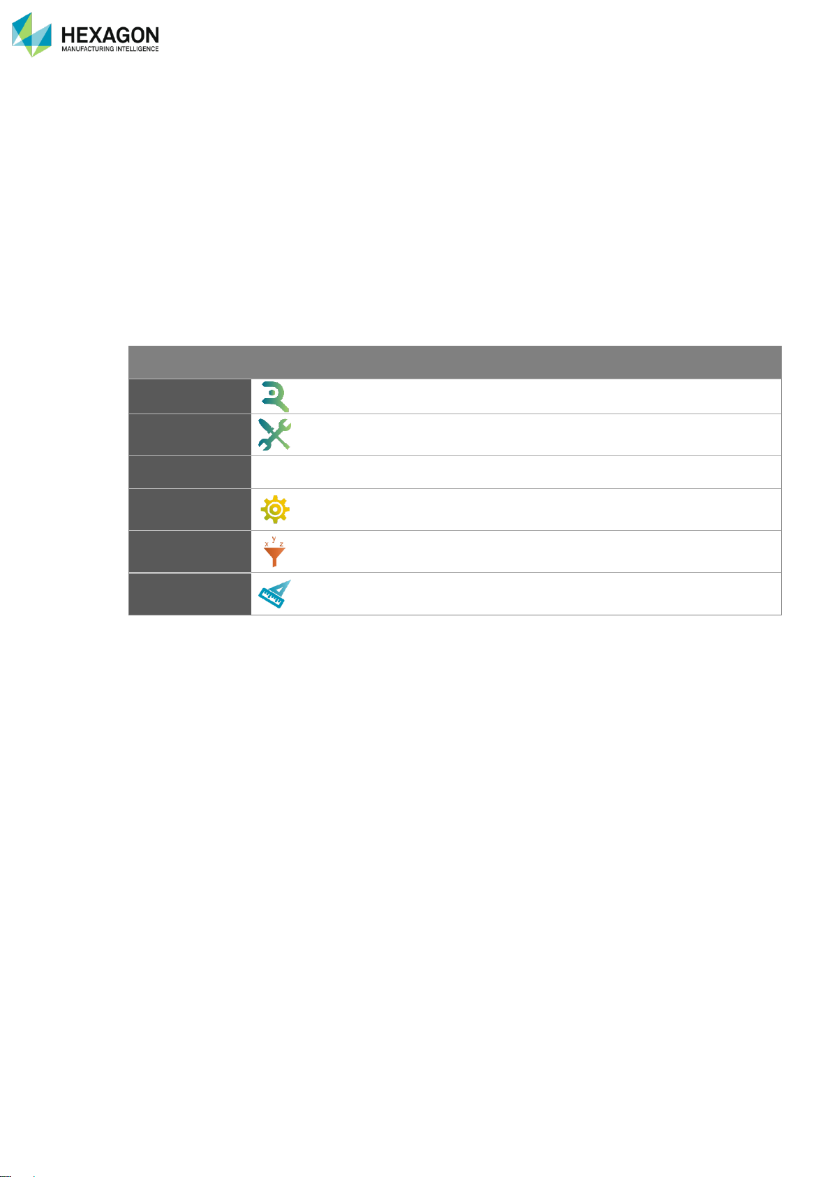
Component
Description
RDS Agent
Main door to all RDS tools. It also provides some quick tools.
RDS Toolbox
Maintenance software for Alignment data synchronization to database, and
arm diagnosis
RDS Service
The driver.
RDS Control
Panel
User’s interface to setup the machine.
RDS Data
Collector
Utility software for Alignments, verifications and accuracy diagnostics.
RDS Quick
Measure
Utility to quickly measure basic dimensions.
In this manual are described RDS Agent, RDS Toolbox (Level1), RDS Control Panel, RDS Arm aid and
RDS Quick Measure.
RDS Data collector is explained in “RDS Data Collector Manual”
RDS Level 2 is explained in “RDS Technician Manual” (Technician profile only)
A.2 RDS LEVELS AND SECURITIES
There are different types of installations:
• Standard installation (End-User): standard installation for end-user profile (Level1).
• Calibration installation: only for technician profile (Level2).
Some functions are protected according to the RDS user level (see §B RDS user levels).
Page 11
Presentation - Installation
H000002007-RDS User Manual │Version 5.0.0 (2018-09-17) │10
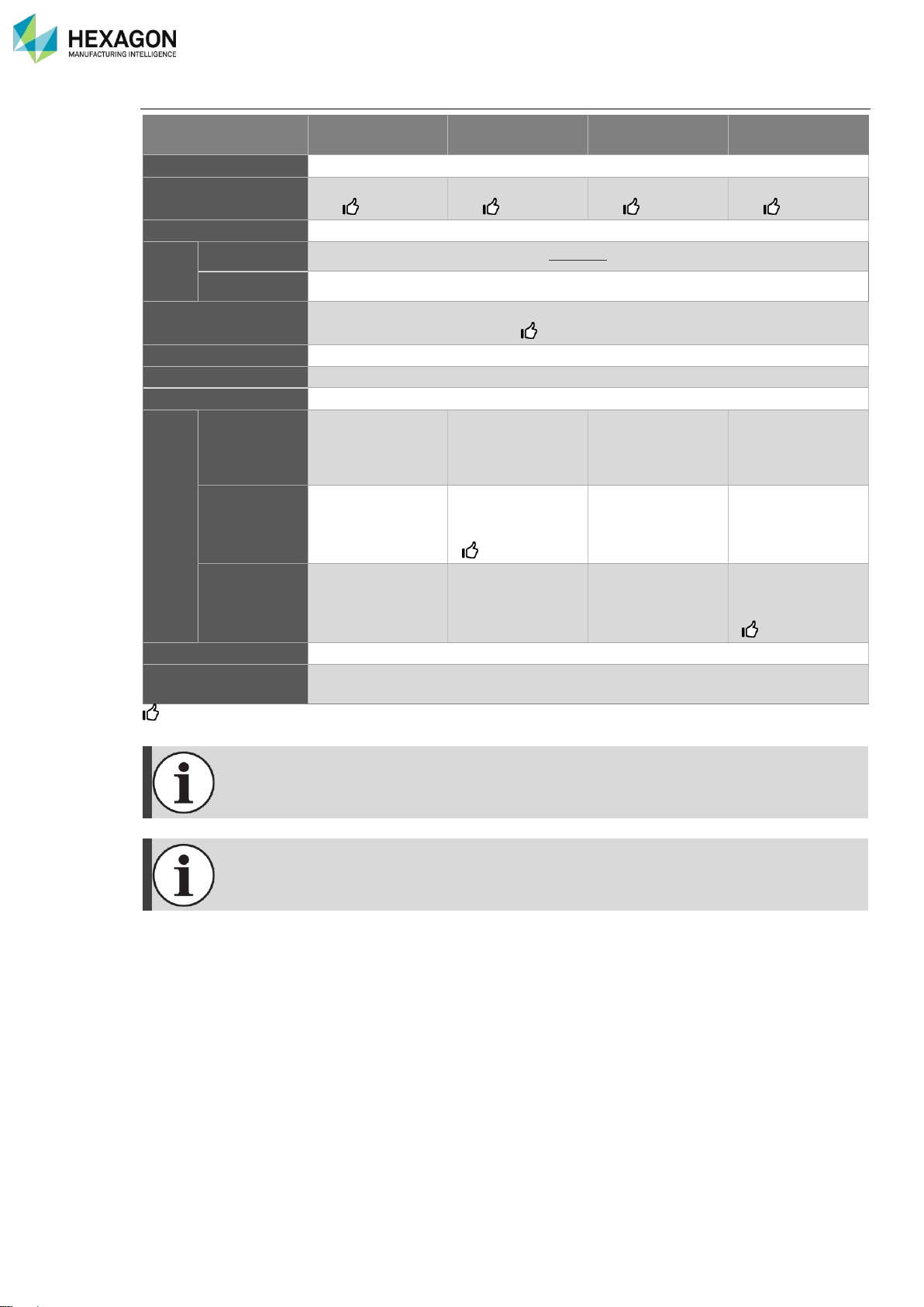
A.3 SYSTEM REQUIREMENTS
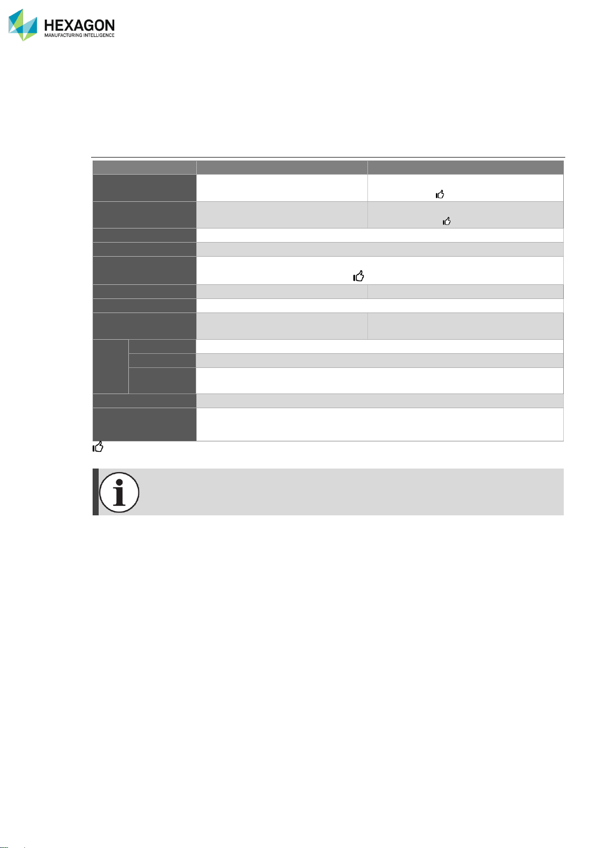
The following information presents the computer minimum required specifications depending on the final
application.
Always ensure that the application software you are using is not requiring higher specifications.
Probing and tubing
Tubing / Probing
Probing with CAD
Processor
2 GHz 2 GHz
: Dual Core
RAM
2 GB
4 GB mini
: 16 GB
Disk space
30 GB
Ports
2 x USB Port
Graphic card
512MB (SVGA graphics card capable of OpenGL representation)
: NVIDIA
Video RAM
1 GB
Screen
HD1080 (1920x1080)
Operating System
Windows7 or Windows10
Pro-32/64 bits
Windows7 or Windows10
Pro-64-bits
Wi-Fi
card
FP2
Any card supporting IEEE802.11b/g/n (Ad-hoc only)
FP3
ONLY Netgear USB-Wi-Fi provided with FP3
FP2+ / FP3+
CP2 / CP3
Any card supporting IEEE802.11b/g/n (Access Point)
.NET
3.5 for W10
Internet connection
For SMART data exchange, an internet connection must be available, and
firewall allows the connection to RDS Toolbox.
: Recommended for higher performances
Wireless connection to the RA7 with FP2 and FP3 may require a specific wireless adapter
with Windows10.
Page 12
Presentation - Installation
H000002007-RDS User Manual │Version 5.0.0 (2018-09-17) │11
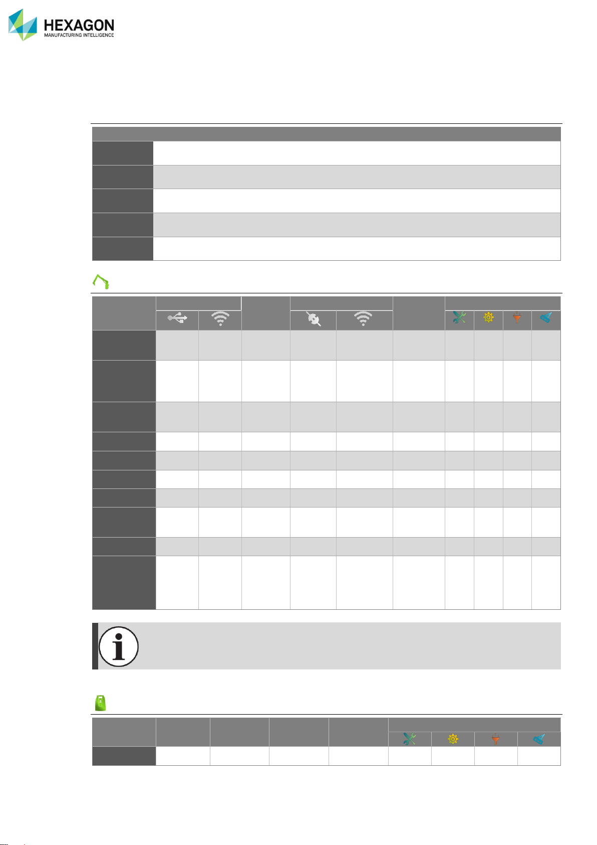
Scanning
RS2-3
HP-L-8.9
RS4
HP-L-20.8
CMS108
RS5
Processor
2 GHz Quadri core
RAM
16 GB mini
: 32 GB
32 GB mini
: 64 GB
16 GB mini
: 32 GB
32 GB mini
: 64 GB
Disk space
60 GB
Ports
USB
2x USB 3.0 Ports
Ethernet
1 x LAN Port Gigabit (on-board)
Graphic card
SVGA graphics card capable of OpenGL representation
: NVIDIA Quadro
Video RAM
2 GB
Screen
HD1080 (1920x1080)
Operating System
Windows7 or Windows10 Pro-32/64 bits
Wi-Fi
card
FP3
ONLY Netgear
USB-Wi-Fi
provided with
FP3
Not supported
Not supported
-
FP3+
Any card
supporting
IEEE802.11b/g/n
Any card
supporting
IEEE802.11b/g/n
Intel N series
Not supported
-
CP3 - -
Not supported
Any card
supporting
IEEE802.11b/g/n
Intel N series
.NET
3.5 for W10
Internet connection
For SMART data exchange, an internet connection must be available, and
firewall allows the connection to RDS Toolbox.
: Recommended for higher performances
It is highly recommended to keep Windows up-to-date.
Wireless connection to the RA7 with FP2 and FP3 may require a specific wireless adapter
with Windows10.
Page 13
Presentation - Installation
H000002007-RDS User Manual │Version 5.0.0 (2018-09-17) │12
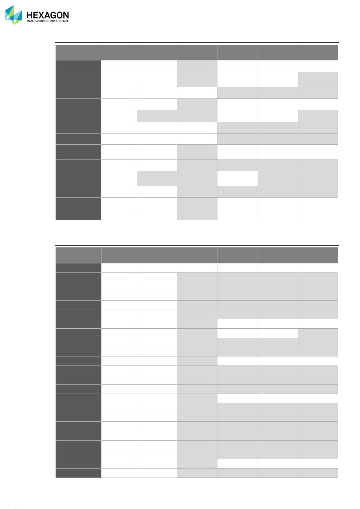
A.4 COMPATIBILITIES
RDS supports the following operating systems and devices:
Operating systems
Windows Xp®
Windows Vista®
Windows7®
Windows10®
32bits
✓
✓
64bits
✓
✓
“Family”
“Pro”
✓
✓
“Ultimate”
Measuring arms
Connection
Probing
Scanning
Tubing
RDS
*
Absolute
Arm RA8
✓ ✓ ✓ ✓ ✓
✓
✓ ✓ ✓
✓
ROMER
Absolute
Arm RA7
✓ ✓ ✓ ✓ ✓
✓
✓ ✓ ✓
✓
Cimcore
CA7
✓ ✓ ✓ ✓ ✓
✓
✓ ✓ ✓
✓
Multi Gage
✓ ✓ ✓
✓
✓ ✓ ✓
Infinite II
Infinite I
Stinger
Sigma /
Omega
Flex
System6 /
R100 /
Armony /
IT5
*: excepted HP-L-8.9
• Wireless connection to the RA7 with FP2 and FP3 may require a specific wireless adapter
with Windows10.
• The RS1 laser scanner is not supported by RDS V5.0.
Measuring Laser Trackers
Reflector
T-Probe
T-Scan
LAS,
LAS-XL
RDS
AT960
✓
✓ ✓
✓
✓
Any other Laser Tracker cannot be used with RDS.
Page 14
Presentation - Installation
H000002007-RDS User Manual │Version 5.0.0 (2018-09-17) │13
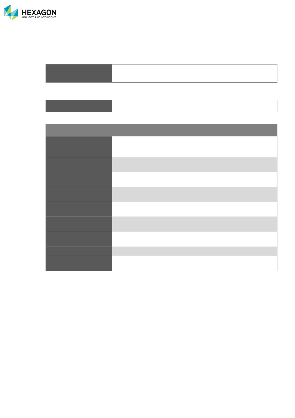
Partner application software compatibilities
Min V°
Contact &
TTP
Tube Probe
RSx /
HP-L-8.9
CMS108/
HP-L-20.8
Perceptron
Pc-Dmis
2011MR1
✓ ✓
✓
Pc-Dmis
Touch
1.0.0
✓
TubeShaper
1.0.0
✓
✓
3DReshaper
6.3
✓ ✓
✓
Visi
2018R2
✓
Romosoft
2.05
Docs
3.0
Spatial
Analyzer
2011
Quindos
7
Bending
Studio
TubeInspect
PolyWorks
12.0.7
✓ ✓
✓
Verisurf
X5
: Implemented by the software, but not tested and validated by Hexagon Manufacturing Intelligence
Other application software compatibilities
Min V°
Contact &
TTP
Tube Probe
RSx /
HP-L-8.9
CMS108/
HP-L-20.8
Perceptron
3DTubeCAD
Aberlink
30.30
Arcocad
BuildIT
Calypso
5.2.16
DezignWorks
Geomagic
Inca3D
Inspect 3D
MCosmos
Metrolog
13
Metromec
MetroSoft
Point2CAD
PowerInspect
PowerShape
Rapidform
Reverse Eng.
RevWorks
Rhino
SurferNT
Tezet
TopSolid
Page 15

Presentation - Installation
H000002007-RDS User Manual │Version 5.0.0 (2018-09-17) │14
Min V°
Contact &
TTP
Tube Probe
RSx /
HP-L-8.9
CMS108/
HP-L-20.8
Perceptron
TubeExpert
VTube Laser
2.9 (10/2017)
: Implemented by the software, but not tested and validated by Hexagon Manufacturing Intelligence
Page 16

Presentation - Installation
H000002007-RDS User Manual │Version 5.0.0 (2018-09-17) │15
A.5 SMART DATA EXCHANGE (ARMS ONLY)
A.5.1 WHAT IS SMART
RDS software includes a new monitoring system for HEXAGON Arms named SMART (Self-Monitoring,
Analysis and Reporting Technology). By collecting various indicators from the Arm and the computer, this
system will help anticipating failures and loss of performances. The strength of this feature is based on the
consolidation by Hexagon Manufacturing Intelligence and the process of information coming from all
HEXAGON Arms. Thanks to this centralized knowledge, thresholds are adjusted to improve the detection
and prediction of potential failures and loss of performances.
We also included in this version a feature allowing diffusion of news from Hexagon Manufacturing
Intelligence. This information is related to your system settings (the type of Arm, the operating system used,
accessories used...).
NOTICE
SMART main purpose is to prevent from any breakdown or issue. Thus, it is important to let RDS Toolbox
communicate the data to the HEXAGON Server.
Page 17
Presentation - Installation
H000002007-RDS User Manual │Version 5.0.0 (2018-09-17) │16
A.5.2 WHAT TYPE OF INFORMATION DOES HEXAGON MANUFACTURING
INTELLIGENCE COLLECT?
RDS software gathers and stores into the host computer on periodic basis information below:
Standard computer
information
Operating system version, CPU, RAM size, Hard disk, Graphical card,
Network adapters, Version of RDS installed and your regional and
language settings.
This information is generally not personally identifiable and is similar as the information your browser sends
to each website you visit.
Configuration of your Arm
Identifiers, Firmware versions, some properties coming from Arm Specs
as its type and its measuring volume.
Various indicators allowing detecting potential failures and loses of performance. There are
ordered into different categories:
General statistics
How many times arm did a full power on/off cycle, Total time in power-on
state, how long the arm has been connected to RDS, Temperature
measured in the base, 3D distance travelled by the probe
Encoders
information as Temperatures, working status, Count of errors and
warnings, Voltage
Accuracy
time passed since the last Alignment, time passed since the last probe
Alignment, result of last quick check and probe Alignment
USB/WLAN communication
information as How long the arm has been connected using USB or
WLAN, Count of communication warnings or errors
Battery
How many times the battery charger started, time this battery has been
used, Health of the battery, Current charge level
Scanner
Time spent scanning, how long laser was on, how many stripes have been
dropped while scanning
Wrist components
information as Time spent using the integrated camera and Head light,
how many times each button has been actuated
Environment
measurements retrieved by SMART modules
RDS
Count of RDS Toolbox, RDS Data Collector and RDS Control Panel
activations
Hexagon Manufacturing Intelligence doesn't collect or process any personal data or any information which
could be used to identify any individual. It certainly will not contain any personal or contact information
about you (such as your name, address, or phone number).
No data about measurement activities is either collected by SMART.
Page 18

Presentation - Installation
H000002007-RDS User Manual │Version 5.0.0 (2018-09-17) │17
A.5.3 HOW DOES HEXAGON MANUFACTURING INTELLIGENCE USE
COLLECTED INFORMATION?
Collected information will be used by Hexagon Manufacturing Intelligence in different ways:
Firstly, all collected information will be used to tune the thresholds allowing the detection of potential failures
and losses of performances. Adjusted thresholds are regularly sent to the field.
If potential problems are detected, one of our affiliate or subsidiary (i.e. service centres) may contact your
company to help you avoiding a complete breakdown of your system. Hexagon Manufacturing Intelligence
will provide those companies only the information they need to deliver the service. They are required to
maintain the confidentiality of this information and are prohibited from using it for any other purpose.
Collected information is also used to propose you interesting news from Hexagon Manufacturing
Intelligence. These news are related to your system settings (Arm type, accessories mounted on the Arm,
operating system language...). News are never sent to a specific customer but to a group or all of them.
Statistic reports will be generated. They will be used by Hexagon Manufacturing Intelligence only to know
how our products are used. It could lead to improvements of existing products and design of new ones.
A.5.4 PRIVACY PROTECTION
Hexagon Manufacturing Intelligence is committed to protect your privacy. Hence, we are not collecting or
processing any personal data or information. This user information statement explains how Hexagon
Manufacturing Intelligence uses and protects the data and information we collect.
We may disclose collected information to affiliate partners (i.e. service centres) when we judge necessary
to inform you about a possible failure or the need of maintenance services on our behalf.
We do not rent, sell or otherwise disclose collected information with unaffiliated third parties.
Hexagon Manufacturing Intelligence has implemented reasonable physical, technical and administrative
security standards to protect collect information from loss, misuse, alteration or destruction.
Our service providers and agents are contractually bound to maintain the confidentiality of collected
information and may not use the information for any unauthorized purpose.
A.5.5 DEACTIVATION
By default, the possibility to collect the above-mentioned information is enabled. You are entitled and able
to disable this function at any time.
To disable this function and discontinue your participation as well as to enable, or to select participation at
a later stage, please refer to chapter D.4 SMART.
NOTICE
Disabling transmission of SMART data to Hexagon Manufacturing Intelligence is not advised. If you do
this, it will make difficult diagnosing potential problems with your equipment. This could increase machine
downtime.
A.5.6 FURTHER INFORMATION
Further information regarding the SMART system can be found in RDS Control Panel, in the SMART tab.
Page 19
Presentation - Installation
H000002007-RDS User Manual │Version 5.0.0 (2018-09-17) │18
A.6 INSTALLATION
It is recommended to proceed Windows Update before the installation of RDS, to ensure the
all the necessary components are installed.
To ensure a good quality of the interface, it is advised to set the size of text in Windows® to
100%.
Application Software
The measurement software (PCDMIS, TubeShaper, and any other software) can be
installed before or after RDS: please see in appendix or follow the instructions of the
measurement software for this installation.
If a legacy version of RDS (up to RDS V4) is already install, you may need to uninstall it
manually.
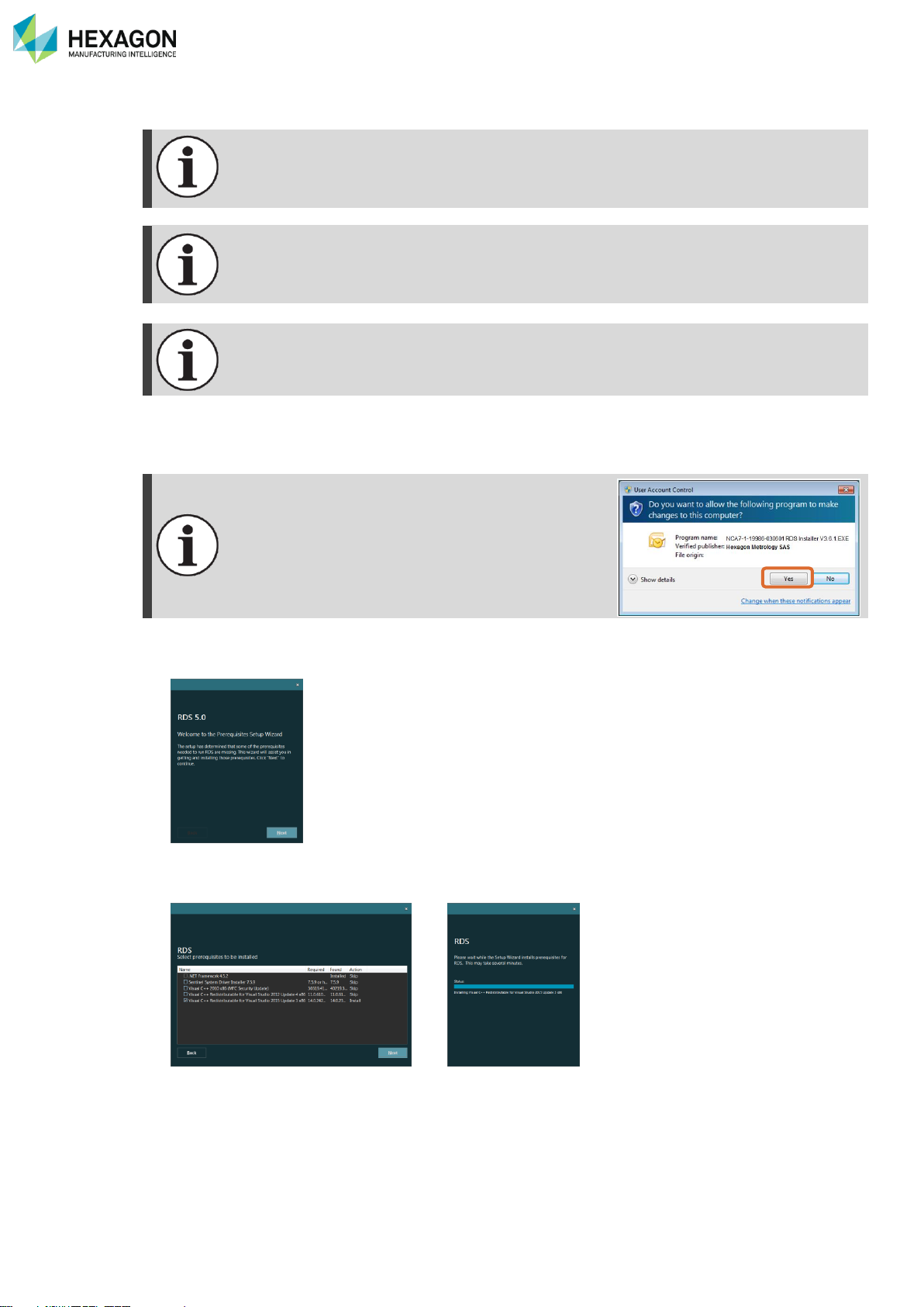
1. From the Installation stick, run “Menu.exe" or “Setup.exe”. RDS installation can be run also directly by
running “RDS Installer V#.#.#.exe” located on the RDS folder or from a downloaded file.
Depending on the computer security settings (User
Account Control), a confirmation may be asked: press
“Yes”.
2. Select “Install RDS”: the following window appears. Click on {next}.
3. Prerequisites checking: check and select the appropriate needed tools and click on {next} (the selected
components are installed).
4. Once the dependencies installed, click on next to proceed with the RDS installation
Page 20
Presentation - Installation
H000002007-RDS User Manual │Version 5.0.0 (2018-09-17) │19
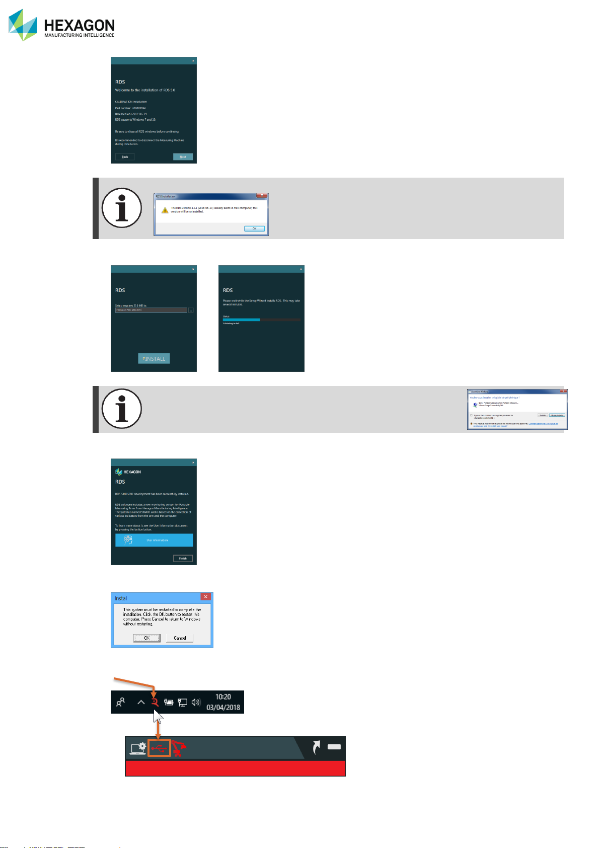
Any existing installation of RDS needs to be removed: acknowledge.
5. Select the destination path and click on next: let the installation proceeding.
The installation of the USB drivers may require a confirmation.
6. At the end of the installation, read the user information and press Finish.
7. If Windows® asks for computer restart, press “OK”.
8. Set-up the connection to the machine.
Page 21
Presentation - Installation
H000002007-RDS User Manual │Version 5.0.0 (2018-09-17) │20
NOTICE
Disabling transmission of SMART data to Hexagon Manufacturing Intelligence is not advised. If you do
this, it will make difficult diagnosing potential problems with your equipment. This could increase machine
downtime.
RDS Toolbox requires the authorization to communicate with the networks to access the
HEXAGON Server.
Ensure that RDS Toolbox is registered for Windows® firewall or any other firewall to access
internet through the network.
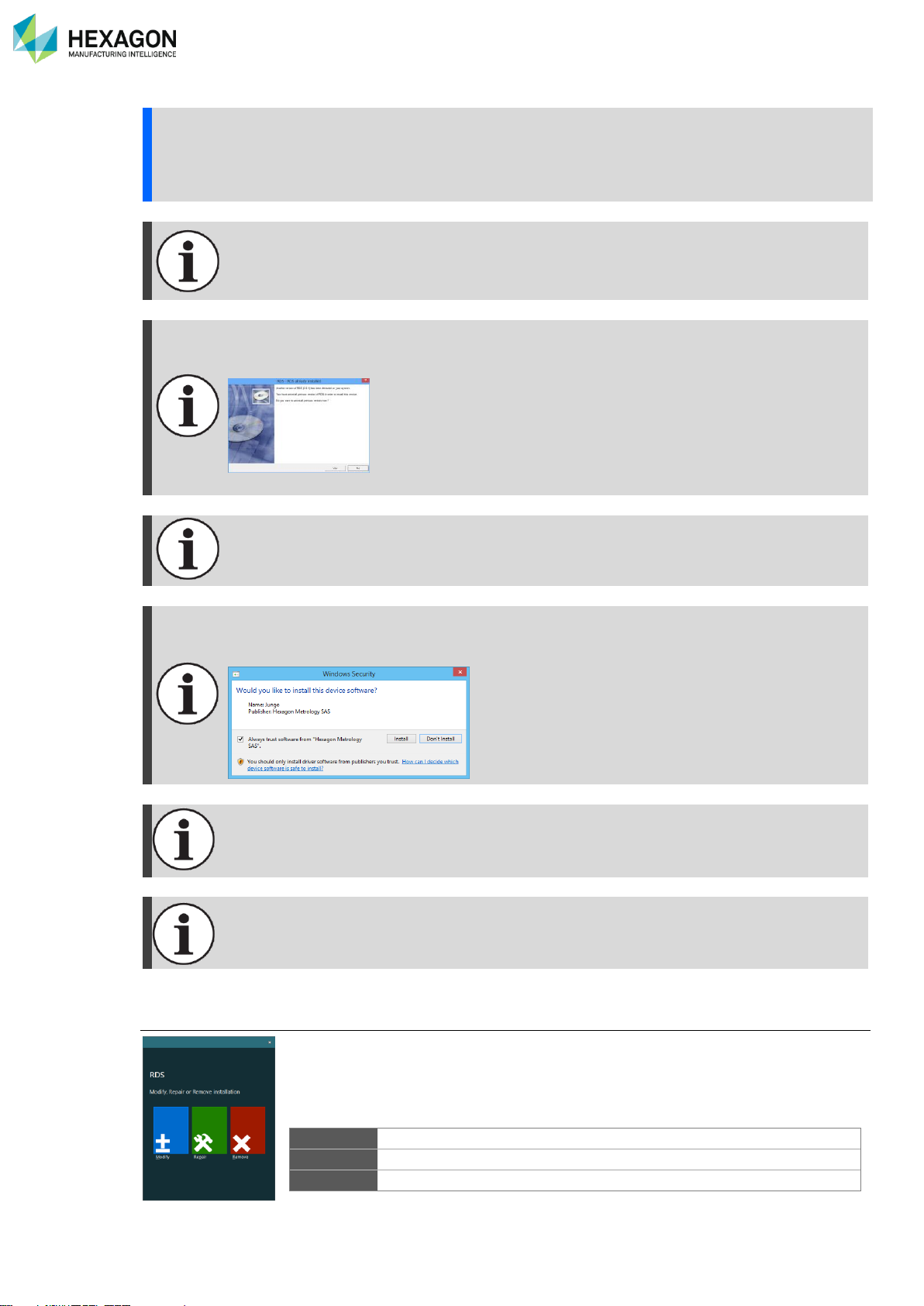
When updating to a newer version, RDS must first be uninstalled, to be able to install the new
version: during the update installation, click on YES to uninstall the previous version before
processing to the new installation.
All settings, configuration and options are preserved.
It is recommended to disable any firewall as it may prevent RDS from functioning properly.
Depending on the version of Windows®, it may be necessary to confirm some message
boxes or allow some installation such as Jungo driver installation, dotnetfx, netfx, Sentinel
driver…
Windows® .NET Framework 3.5 needs to be activated. If not, RDS installation will try to install
it or prompt to activate it: Access Windows® control panel > group “Programs” > “Turn
Windows features on or off”.
In case of using RDS on a user profile, Registry needs to be open in writing
Location: HKEY_LOCAL_MACHINE\SOFTWARE\ROMER.
Uninstall
When running the installer on a computer pre-equipped with RDS V5, several options
are proposed:
Modify
Permits to choose components to keep or remove.
Repair
Reinstalls RDS keeping the settings
Remove
Removes RDS software package.
Page 22
Presentation - Installation
H000002007-RDS User Manual │Version 5.0.0 (2018-09-17) │21
A.7 QUICK REFERENCE
Topic
How to?
Page
Use the manual
Find with keyword
Jump to a link
Go back
Ctrl + F
Click on it
Alt + ←
Install RDS
18
Setup the measurement software for RDS
184
Connection
Setup a USB connection
42
Setup a Wireless connection
50
Configure the Wi-Fi chipset
171
Setup an Ethernet connection
51
Probe
Program a probe
170
Align a probe
57
Delete a probe
58 Modify a probe
60
Reference
Move the arm by a Leap-Frog
78
Activate a GridLok
79
Various settings
Change the sound volume
27
Modify the mouse settings
82
Switch on/off the wrist camera
84
Configure the wrist camera
84
Switch on/off the wrist headlight
54
Activate the Haptic feedback
82
Scanner
Configure a HEXAGON scanner
64 Save a scanning profile
66 Use a scanning profile
32 / 36 / 66
Upgrade the scanner
171
Quick Measure
Proceed a quick measurement
179
Backup / Restore
Backup the arm data
136 Restore the Arm data
139
Arm Status
Survey the arm indicators
150
Show the status of the current arm
143 / 114 / 39
Show the status of a not connected arm
142
Options
Ask / Add a feature code
89
Vault
Get the packages of an arm
128
Send a package by E-Mail
137
Maintenance
Record a signal analysis
171
Alerts
Hide the notifications
147 / 105
Analyse an alert
146
Page 23
RDS User Profiles
H000002007-RDS User Manual │Version 5.0.0 (2018-09-17) │22
B. RDS USER PROFILES
Different profiles exist to use RDS; according to the selected profile, functions may be available or not. This
provides security on the configuration of the system.
According to the user profile, the prohibited functions or settings may concern advanced settings, Alignment
operations (in RDS Data Collector), and any function which could result on a risk of wrong measurements,
or potential damage on the system.
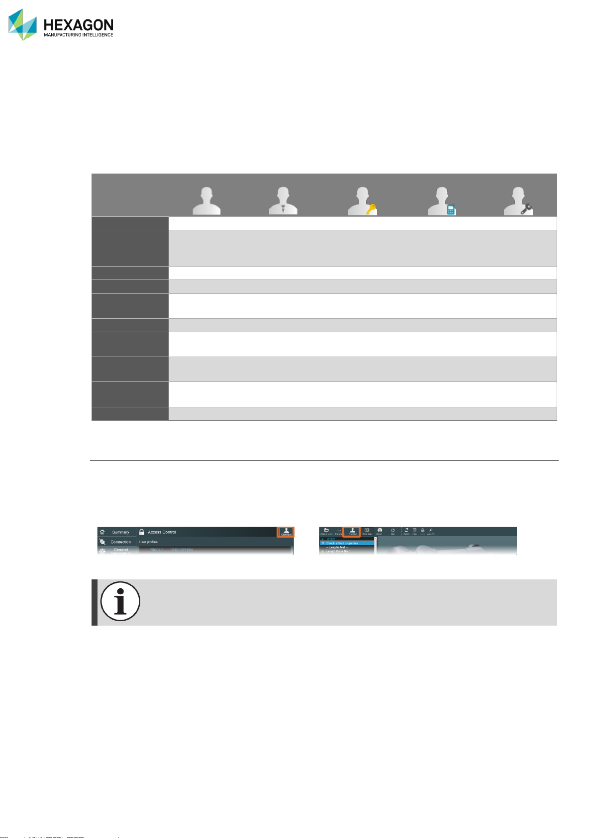
5 levels of profiles are defined, respectively protectable or protected with a password or with a feature code.
Standard
Advanced
Admin
Support
Service
Level 1 2 3 4
5
Protection
None
Password
(default =
“Advanced”)
Password
(default =
“Administrator”)
Feature Key /
Password
Feature Key /
Password
Verifications
✓ ✓ ✓ ✓ ✓
Alignments
✓ ✓ ✓
✓
Incorrect
Alignments
✓
✓
Basic settings
✓ ✓ ✓ ✓ ✓
Advanced
settings
✓ ✓ ✓
✓
System
parameters
✓
✓
Password
change
✓ ✓ ✓
Service tools
✓
Activate an End-User profile
Standard user is the default profile.
RDS always starts with the default profile. When the user switches to another profile, this new selection
remains active until a new selection is done or until RDS is restarted.
The selection of a User profile can be done indifferently in RDS Control Panel or in RDS Data Collector.
RDS Control Panel
RDS Data Collector
As soon as a Feature code is activated (and valid), then the corresponding profile (Support
or Service) becomes the default one.
Page 24
RDS User Profiles
H000002007-RDS User Manual │Version 5.0.0 (2018-09-17) │23
Activate hidden profile
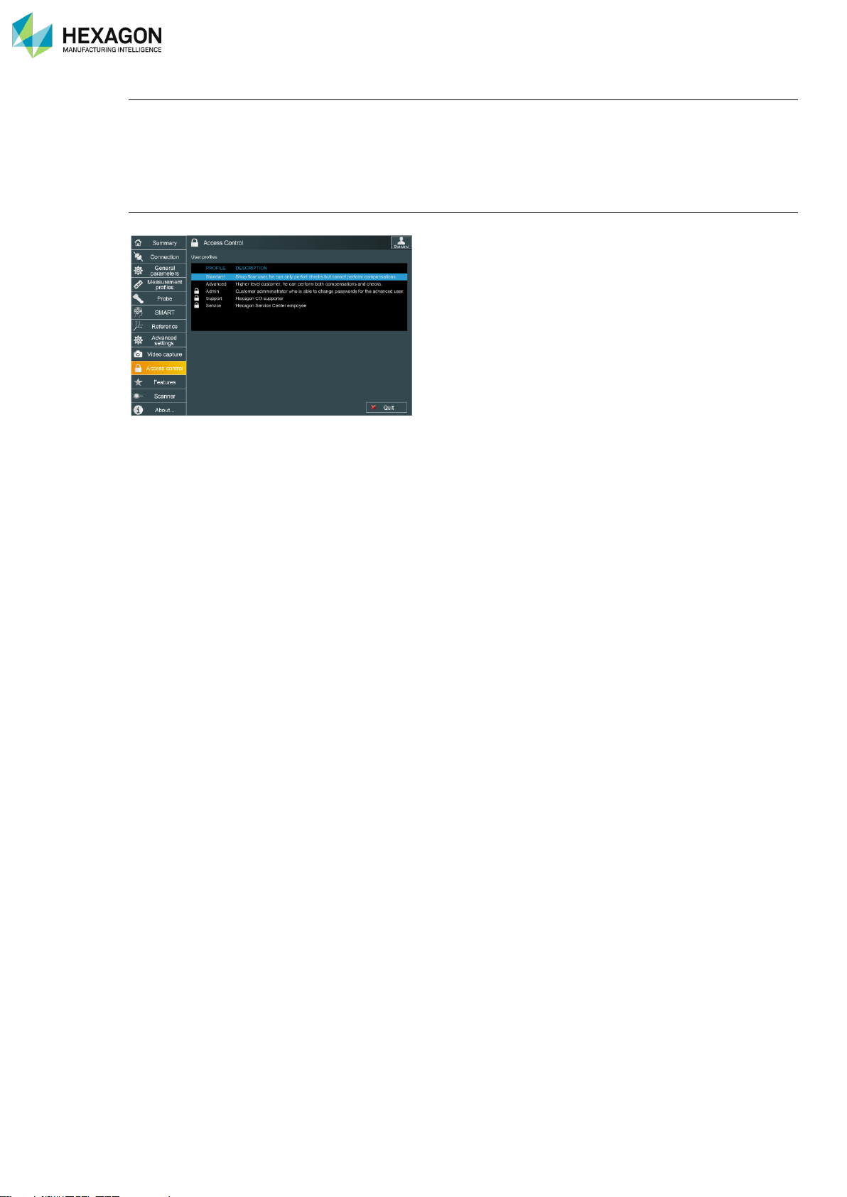
By default, End-Users can access only Standard and Advanced user profiles (upper profiles – Admin,
Support, and Service – are hidden).
To activate one upper profile, select the Advanced profile, and enter the appropriate password or enter the
activation code in “Features” tab.
Change passwords
To change the password of one profile, the Tab “Access Control” in RDS Control Panel can be used.
Page 25
RDS Agent
H000002007-RDS User Manual │Version 5.0.0 (2018-09-17) │24
C. RDS AGENT
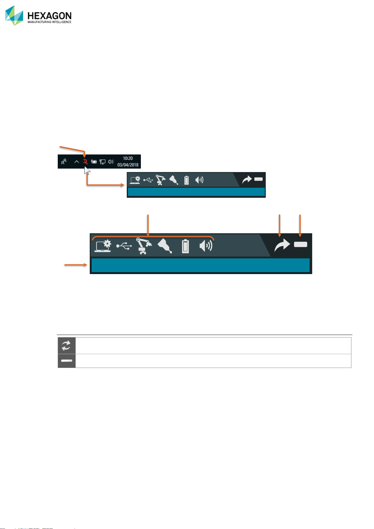
RDS Agent is the user entry door to RDS. It provides
• Basic status information
• Access to the RDS Tools
• Quick Access Menu (controlled with the arm)
An icon on the status bar at the bottom of the screen gives access to its interface.
At any moment, it is possible to access those functions, by clicking on RDS icon in the task bar on the right
bottom of the screen, the RDS Agent then appears.
a. System global status
b. System status and quick configuration
c. Access to RDS tools
d. Window control (see below).
Window control
Switches the window size (reduced / medium / maximized)
(When using scanners)
Closes the interface window (the agent remains active)
Home position
b c d
a
Ready to measure
Page 26
RDS Agent
H000002007-RDS User Manual │Version 5.0.0 (2018-09-17) │25
C.1 SYSTEM STATUS
C.1.1 GLOBAL STATUS
One of the purpose of the RDS Agent is to quickly display main information about the status of the system.
When the Agent appears, the global status is shown on the lower line.
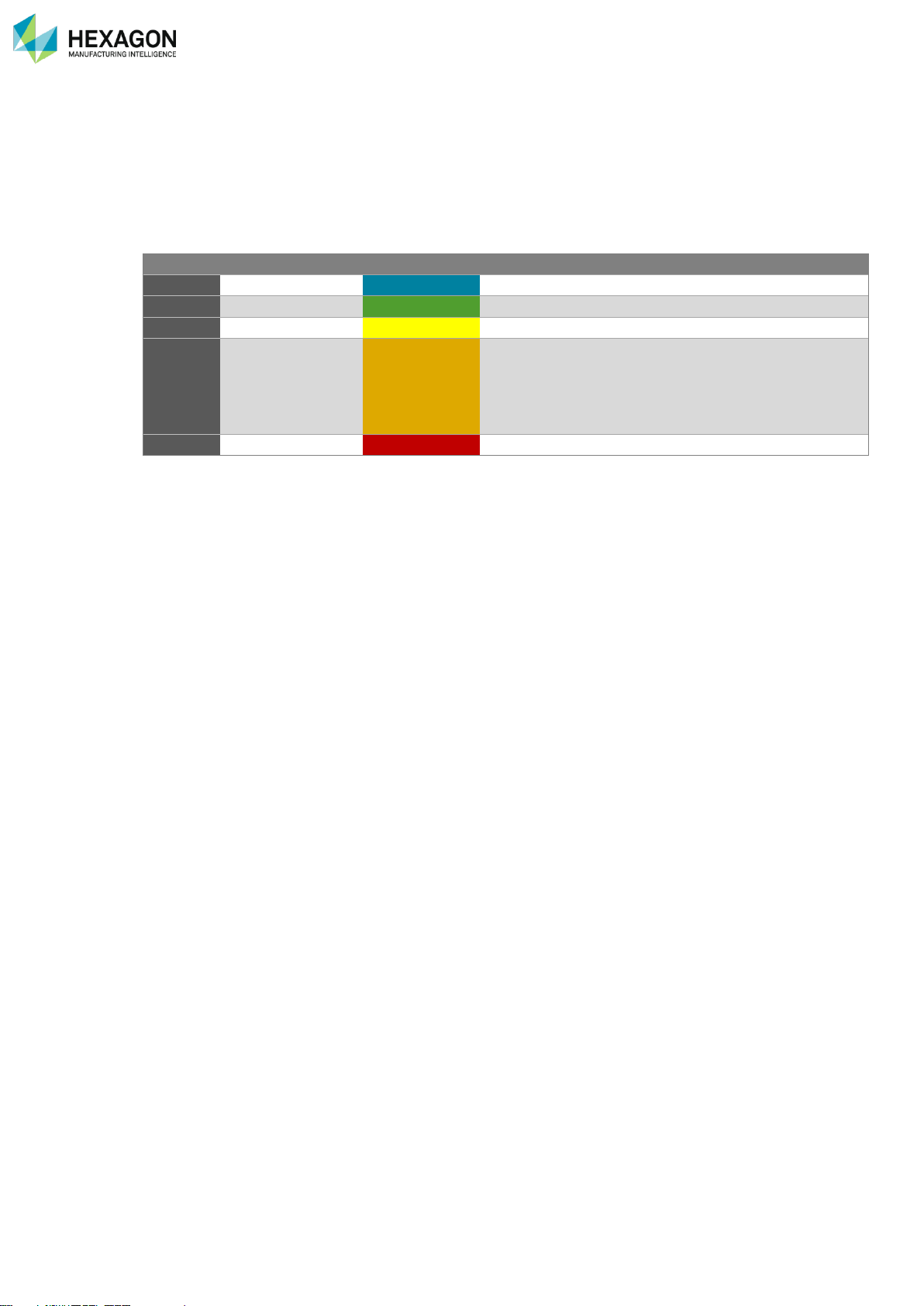
The colours use the following conventions:
Colour
Signification
Status example
Blue
Operational mode
Ready
The instrument is operational (home position)
Green
Ready to measure
Press trigger...
The system is ready to measure
Scanning
Scanning
The system is currently digitizing with a Laser scanner
Orange
Non-critical issue
Axis over limit
The instrument is connected, but an event prevents
from measuring:
Encoder on its limit
No probe mounted
…
Red
Critical issue
Not connected
No instrument is connected, or issue of connection
Page 27
RDS Agent
H000002007-RDS User Manual │Version 5.0.0 (2018-09-17) │26
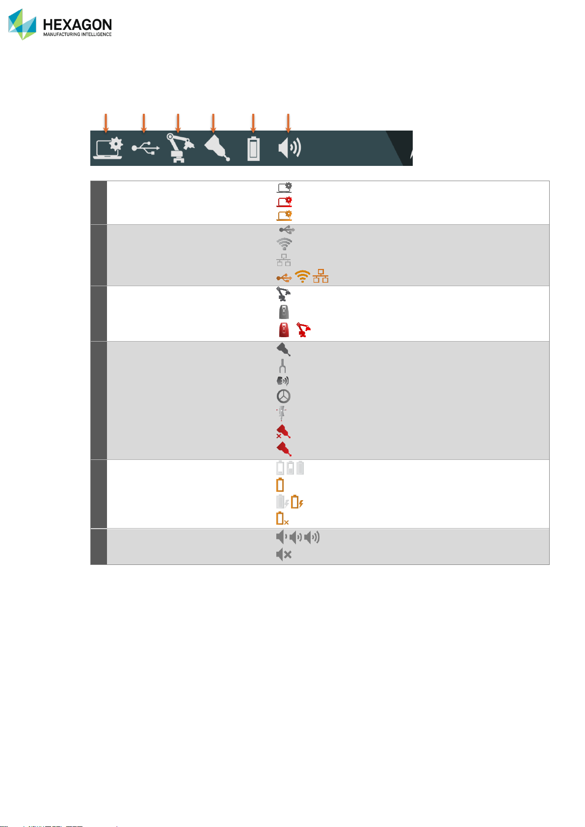
C.1.2 SYSTEM STATUS
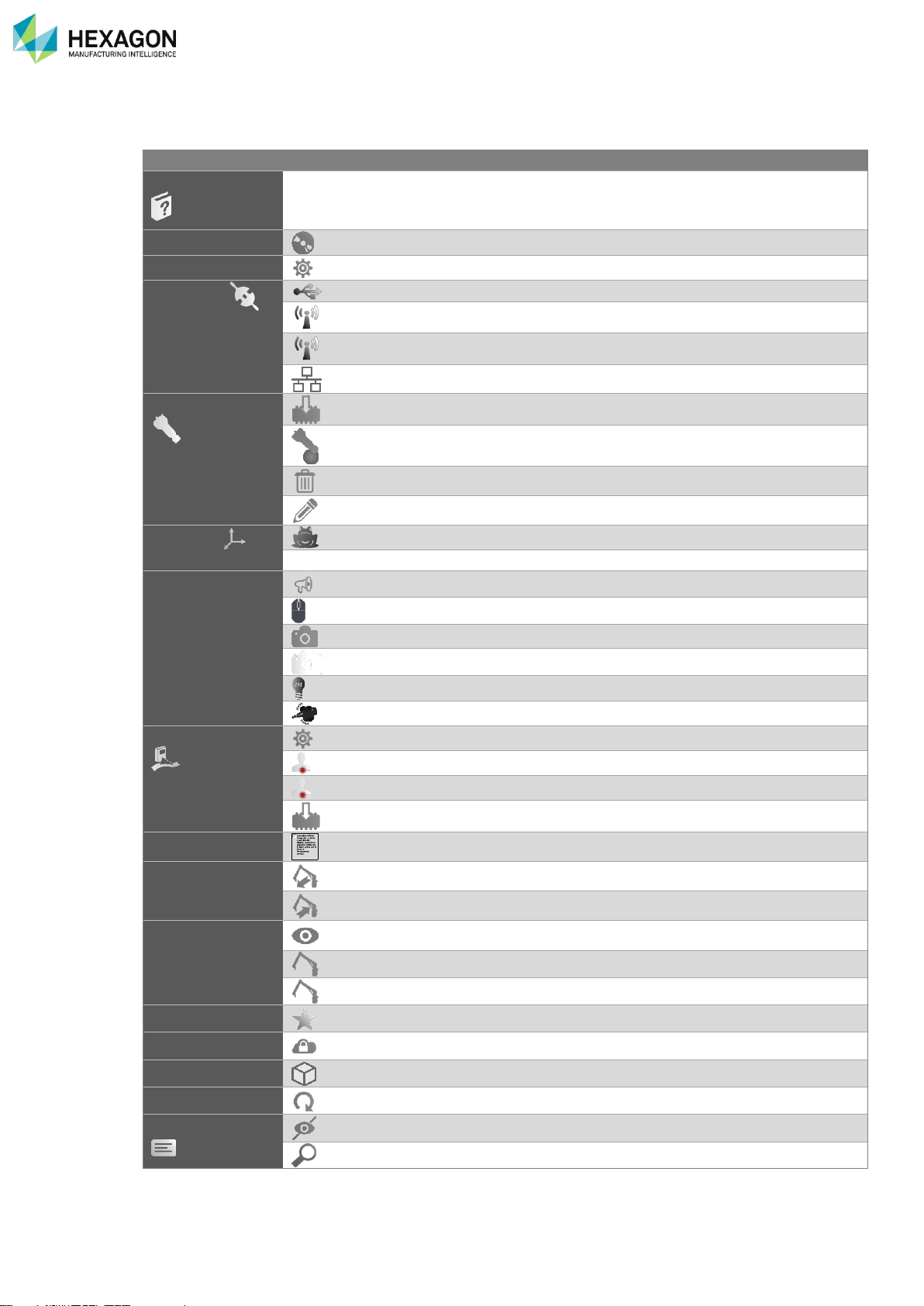
On the left upper line, is shown the status of major components. Clicking on those icons shows the details
or opens the appropriate set-up panel.
a
Status and setup of RDS Agent
RDS is functional
Critical issue (ex: RDS service is stopped)
non-critical issue
b
Type and status of the connection
to the machine
Instrument connected through USB
Instrument connected through WLAN
Instrument connected through Wired Ethernet
/ / Connection issue
c
Type and status of the instrument
The selected type of instrument is Arm
The selected type of instrument is Tracker
/ No instrument of the selected type can be found.
d
Type and status of the probe
The current probe is a contact probe
The current probe is a tube probe
The current probe is a scanner
The current probe is a reflector
The current probe is a T-Probe
No probe is currently detected
Issue with the probe
e
Status of the battery
Battery(ies) level (Low to High)
The battery level is critical
On power supply / the battery is charging
No battery detected
f
Sound level
Sound volume set (Min to Max)
Sound set to zero
a b c d e f
Page 28
RDS Agent
H000002007-RDS User Manual │Version 5.0.0 (2018-09-17) │27
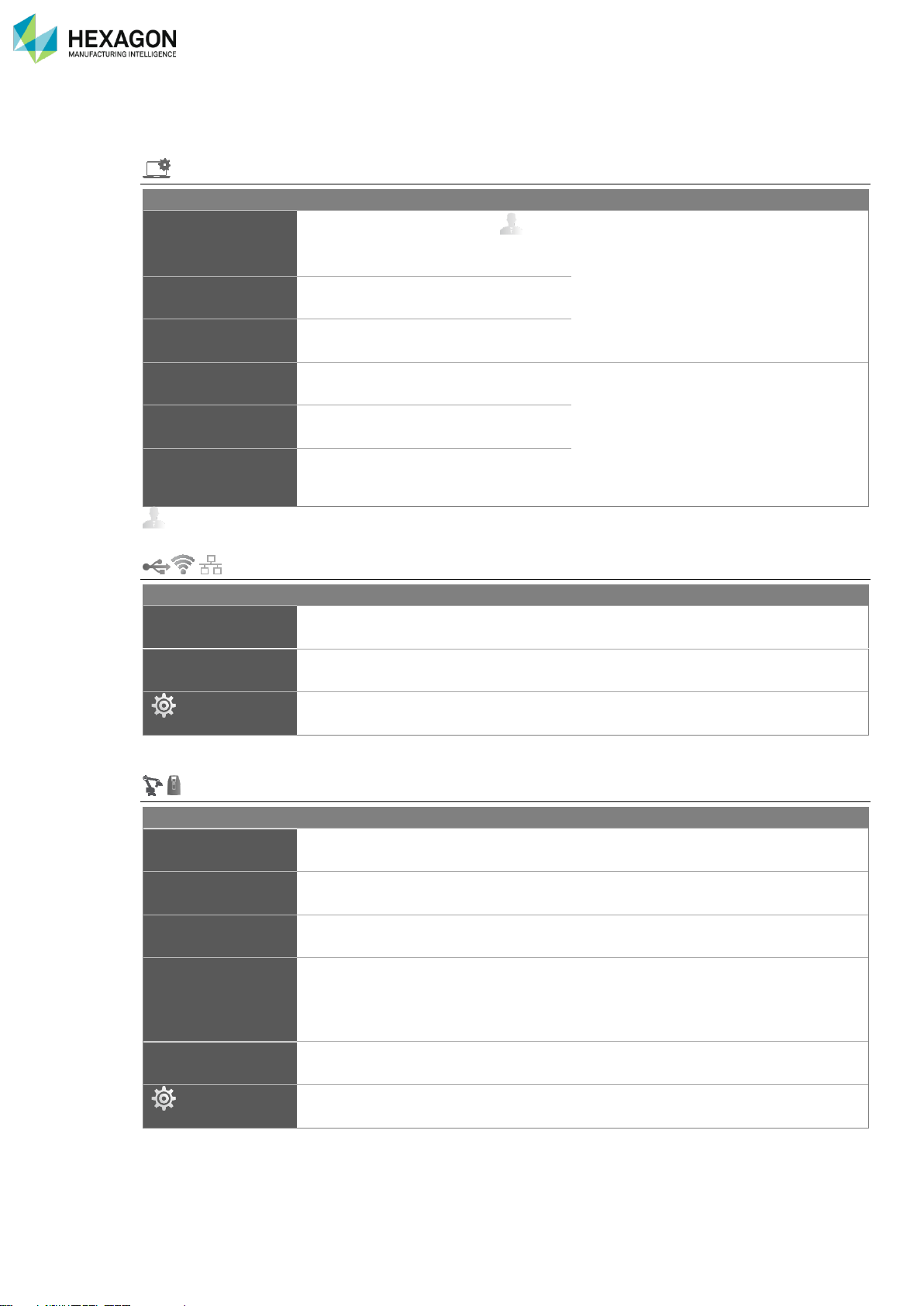
C.1.3 STATUS DETAILS
To get details about one component, click on the wanted icon.
System Status
Item
Status
Action
RDS Service
Running / Stopped
Stop ( ) /
Start
Shows the activity of the component and
gives a quick way to restart it.
RDS Toolbox
Running / Stopped
Stop / Start
RDS Agent
Stop
Minimise window at
start-up
Active / Inactive
(default=inactive)
Activate
Configuration of the RDS Agent window
display.
(default = inactive)
Always on
foreground
Active / Inactive
(default=inactive)
Activate
Opacity
Percentage of
opacity
(default = 100%)
Set the value
: at least advanced user.
Connection status
Item
Type
Shows the type of connection to the machine
USB / WLAN /
Ethernet
Status
Shows the connectivity status
Connected /
Connecting …
Control Panel
Gives access to RDS Control Panel for the configuration
Machine status
Item
Status
S/N
Shows the serial number of the connected instrument, when available
Arm Type
Shows the type of machine (MG, RA7, RA8…)
Extension Pack
Shows the type of Control / Feature Pack (CP1, FP2…)
Temperature
Humidity
Pressure
Gives the current temperature (°C)
• ambient temperature measured by the instrument (onboard sensor)
• external temperature measured by an external sensor (WTS, Bluetooth
sensor…)
Ext. temperature
Gives the current temperature measured by an external sensor (WTS, Bluetooth
sensor…)
Control Panel
Gives access to RDS Control Panel for the configuration
Page 29
RDS Agent
H000002007-RDS User Manual │Version 5.0.0 (2018-09-17) │28
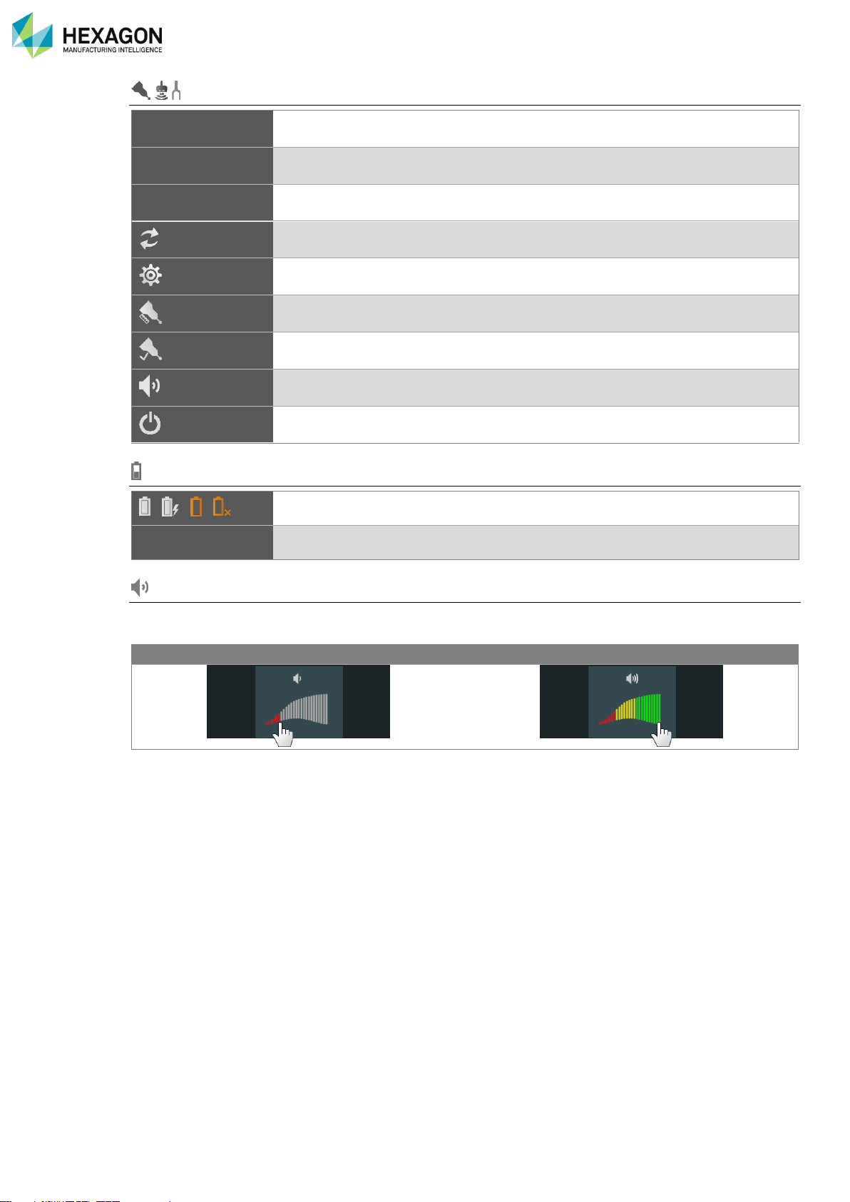
Sensor status (Probe / Scanner / NC Tube probe)
Name
Name of the sensor
Type
Shows the type of sensor (Contact probe / Scanner / NC Tube probe)
Alignment
Shows the date, time and calculation result of last alignment (Alignment) of the
probe.
Switch selection
On RA8-7 axes only: change the probe / scanner selection
Control Panel
Shows more status information (in RDS Control Panel)
Align Probe
Runs the probe alignment process in RDS Data Collector
Check Probe
Runs the probe verification process in RDS Data Collector
Sound guide
Activate / deactivate the Depth sound guide for the scanners
Power off
Power off the HP-L-20.8 / CMS108 scanner
Battery(ies) status
/ / /
Battery status (OK, Low, No battery)
%
Charging level
Sound level (Arms only)
To change the sound level of the arm or the headset, click on the desired.
Lower volume
Higher volume
Page 30
RDS Agent
H000002007-RDS User Manual │Version 5.0.0 (2018-09-17) │29
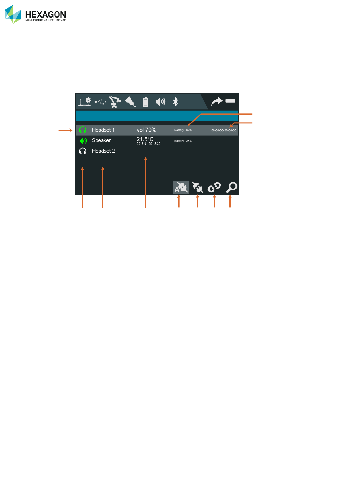
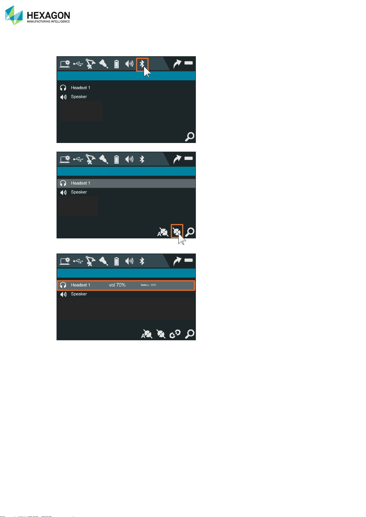
C.2 BLUETOOTH
Wireless accessories can be connected to the new Absolute Arm (RA8).
Their connection is managed in the RDS Agent.
Click on the Bluetooth icon to display the list of available, connected or registered devices.
a. Selected line
b. Type and status
c. Name
d. Current information
e. Battery level
f. Address of the selected device
g. Auto-connection activated (selected device)
h. Connect / disconnect the selected device
i. Unregister the selected device
j. Seek again for new devices
b c d g h i j
a f e
Page 31
RDS Agent
H000002007-RDS User Manual │Version 5.0.0 (2018-09-17) │30
C.2.1 CONNECT A NEW DEVICE
Click on the Bluetooth tab to open the panel: RDS Agent seeks for available devices and lists them.
Select the wanted device and click on Connect.
The device is now ready.
Page 32
RDS Agent
H000002007-RDS User Manual │Version 5.0.0 (2018-09-17) │31
C.3 SHORTCUTS
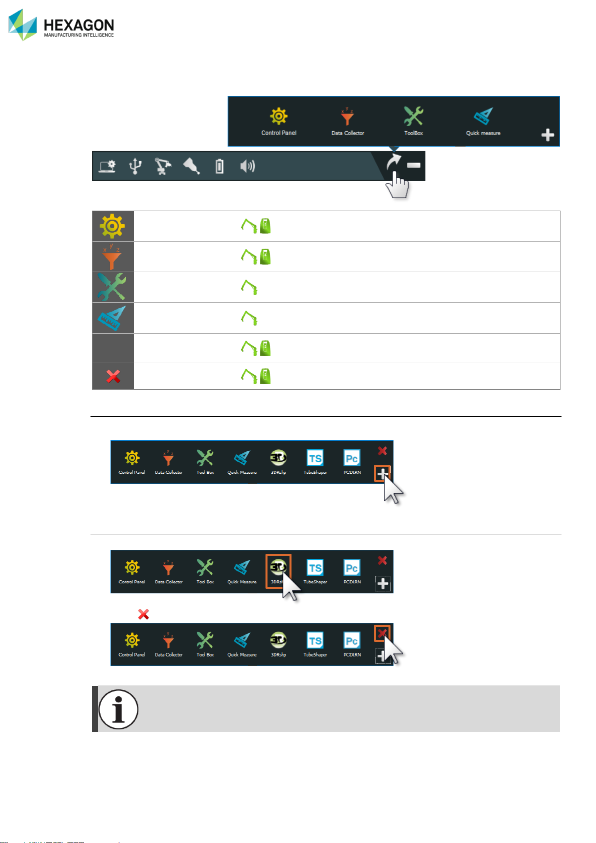
To access the RDS software components, click on the Shortcuts icon.
RDS Control Panel
Full machine and RDS configuration.
RDS Data collector
Instrument and accessories verification and Alignment.
RDS Toolbox
Main interface for the configuration and maintenance.
RDS Quick measure
Tools to do basic measurements.
+
Add a shortcut
Gives the possibility to add a customized shortcut.
Remove a shortcut
Add customized shortcuts
1. Press + to add a new shortcut
2. Browse and select the file (executable or not)
Remove shortcuts
1. Select the shortcut to remove
2. Press
Only customized shortcuts can be removed.
Page 33
RDS Agent
H000002007-RDS User Manual │Version 5.0.0 (2018-09-17) │32
C.4 SCAN VIEW
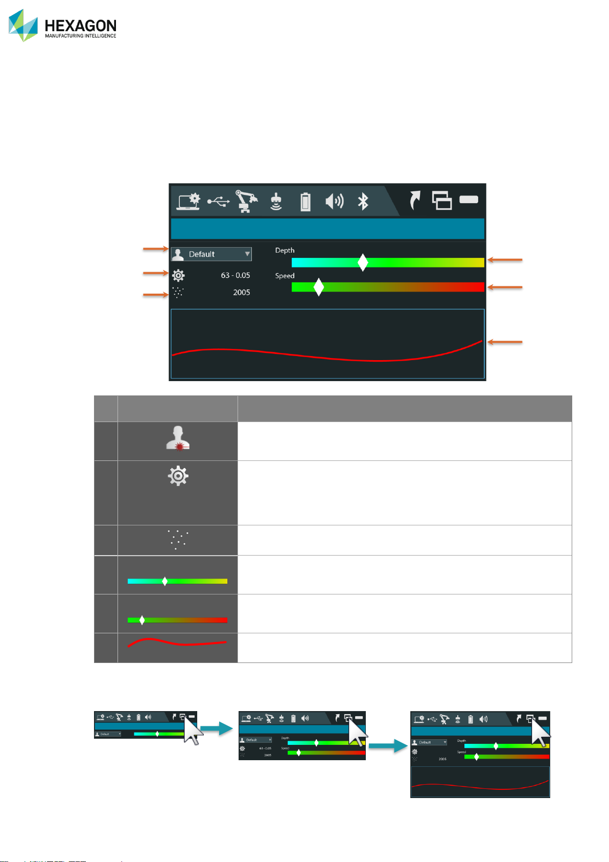
When a HEXAGON scanner is detected on the arm or the tracker, the RDS Agent provides useful tools for
digitizing.
C.4.1 DESCRIPTION
By default, the window is displayed minimized. Following information and options are available:
Item
Description
a Current scanning profile and profile selection.
(See §D.7.2)
b Access to the scanner settings (press on the button)
Main scanner mode :
- RS5 / HP-L-8.9: Exposure + Auto / Manual modes
- HP-L-20.8: Width + Points spacing
c Nb of points per stripe
d
Depth
Indicator bar graph showing how target is placed against scanner Z-field.
Only in capture mode
e
Speed
Bar graph indicator telling the user if he is moving the arm too fast while
scanning. If the bar is out of range, RDS prevents from getting points.
f 2D view of the scan line
C.4.2 MINIMUM / EXTENDED WINDOW
The window size can be modified by clicking on the resize button:
Extended window can then be displayed: to the basic items, is added the video of the scanner.
a b d
e
f
c
Page 34
RDS Agent
H000002007-RDS User Manual │Version 5.0.0 (2018-09-17) │33
C.5 QUICK ACCESS MENU (ARMS ONLY)
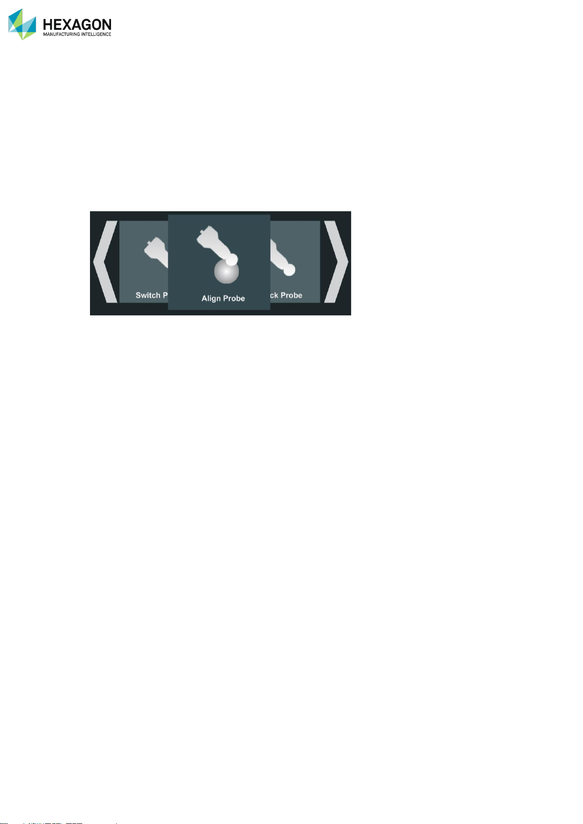
The Quick Access Menu (“Q.A.M.”) is a functionality of the RDS Agent, providing main useful actions very
easily from the wrist of the arm without the need of going back to the computer. The Quick Access Menu is
similar on the Wrist Display on the RA8 – 7 axes.
Actions may be
• Display system status information
• Access to verification or Alignment
• Control Main settings
• Real time feedback for scanning
The Quick Access Menu contains very basic and easy interface and use:
• Left-Right: Make your choice
• Click: validate the choice.
Page 35
RDS Agent
H000002007-RDS User Manual │Version 5.0.0 (2018-09-17) │34
C.5.1 CONTROL THE Q.A.M.
Open the Q.A.M.
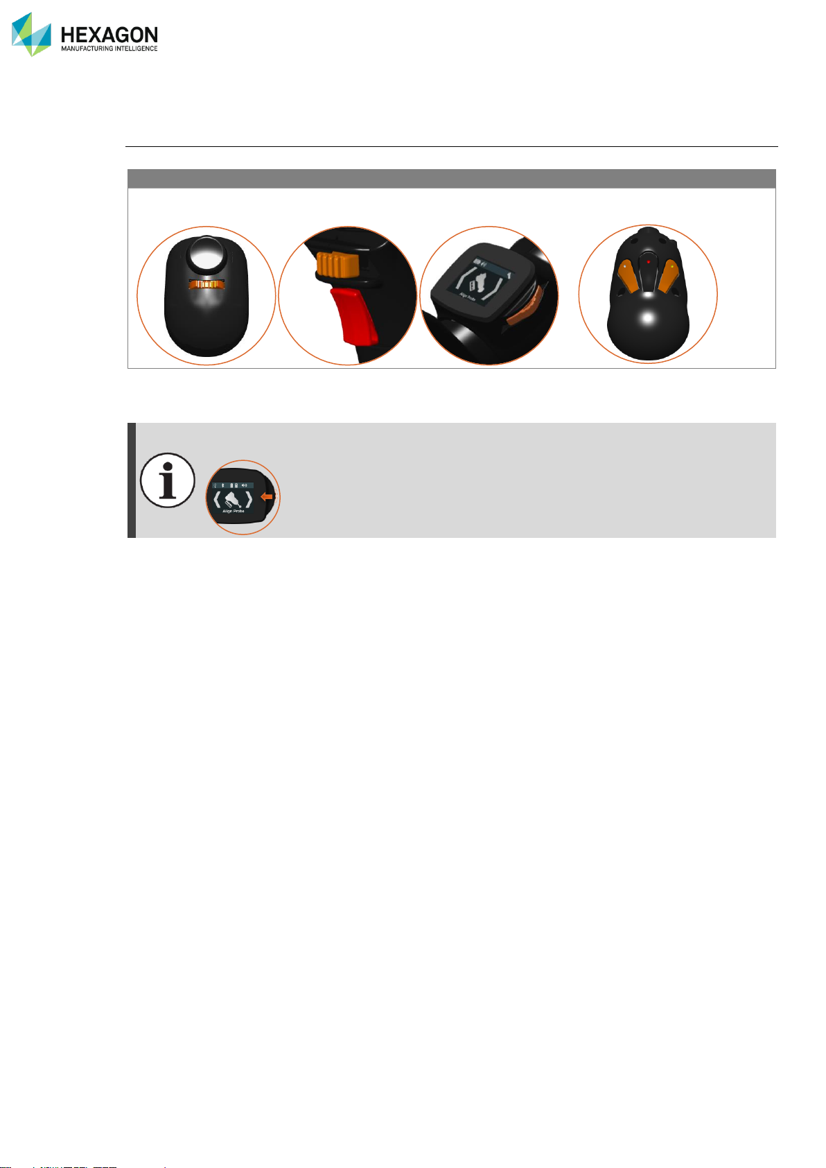
The Quick Access Menu can be opened simply with a press on the buttons on the Wrist of the Arm
RA8
Other arms
Simply press on the 3States Button (6 or 7 axes)
Press simultaneously the left
and right buttons.
Then the Q.A.M. appears on the lower line of the RDS Agent.
On the wrist of the ROMER Absolute Arm RA8-7axes, the Wrist Display provides the same
menu.
Page 36
RDS Agent
H000002007-RDS User Manual │Version 5.0.0 (2018-09-17) │35
Navigate
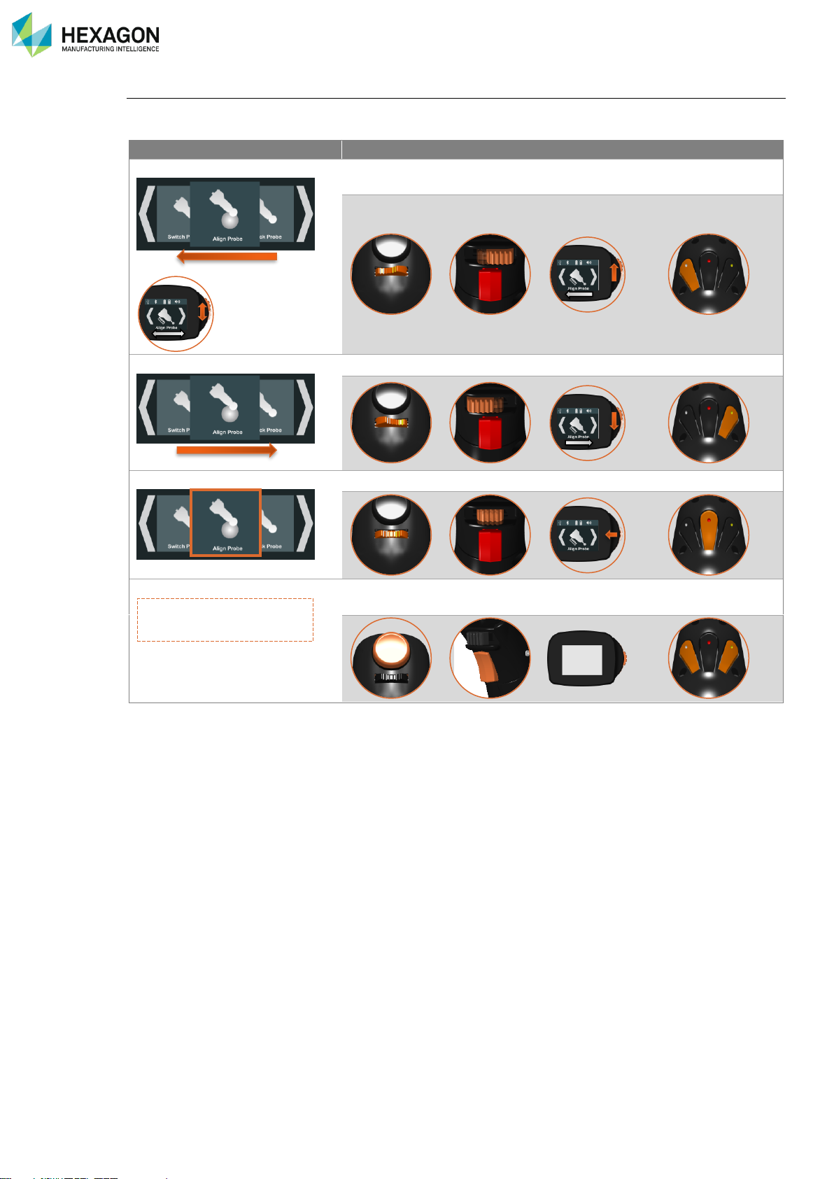
The wanted action can be easily selected by going left or right with the buttons of the wrist.
RA8
Other arms
Previous action - left
Press the 3-States button to the left
Press left button
Next action
Press the 3-States button to the left
Press right button
Validate the choice
Press the 3-States button down
Press Middle button
Exit the Q.A.M.
Press the Trigger button
Press left & right
buttons
Page 37
RDS Agent
H000002007-RDS User Manual │Version 5.0.0 (2018-09-17) │36
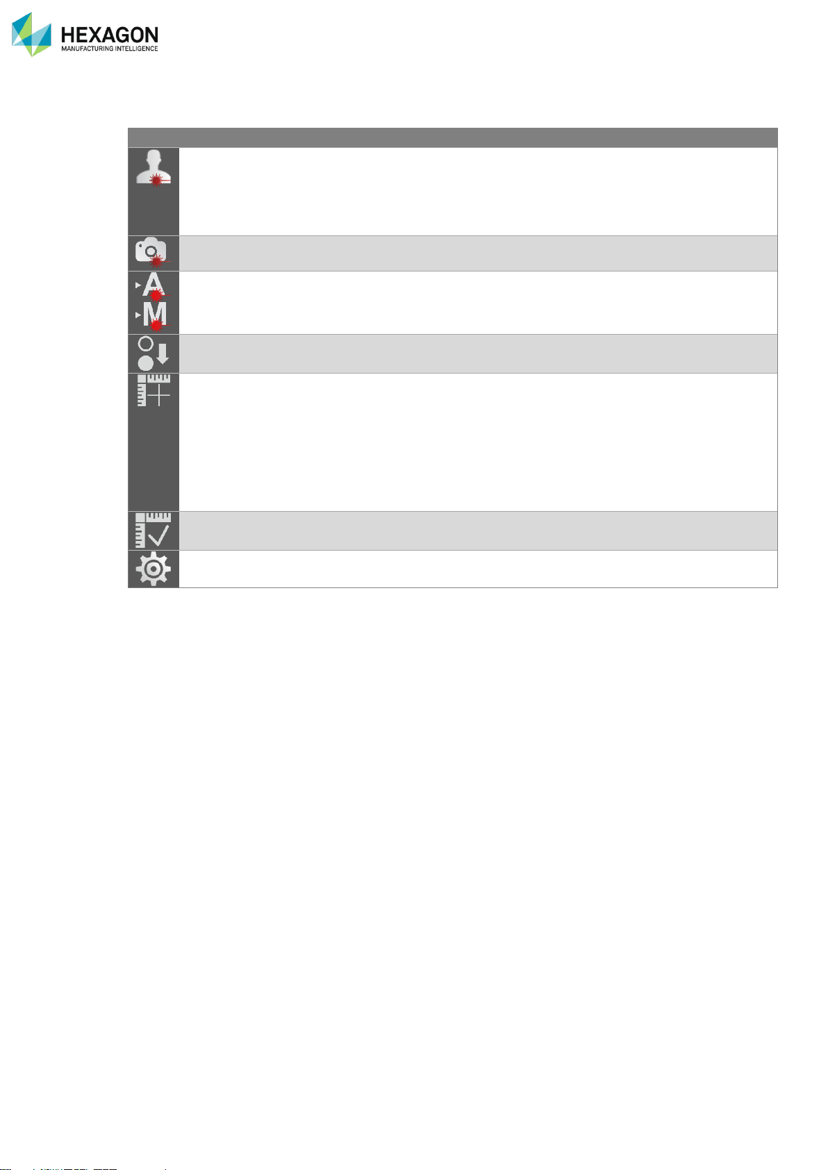
C.5.2 AVAILABLE ACTIONS
Change scanning profile
All Laser
scanners
Offers the choice of profiles and activates the chosen
one.
Profile1
Profile2
…
Capture exposure
RS2-5
scanners
Starts the auto-static exposure
Switch exposure mode
RS2-5
scanners
Switches Static-Dynamic exposure modes
Switch sensor
RA8-7
Switches to the upper or lower sensor location
Align probe
All
systems
Offers the choice of Alignment method and runs the
RDS Data Collector script:
• Sphere
• Sphere with reference
• Plane
• Plane with Reference
• Single point (contact probe only)
Check probe
All arms
Runs the appropriate script in RDS Data collector
Control Panel
All arms
Opens RDS Control panel for settings
Page 38
RDS Control Panel
H000002007-RDS User Manual │Version 5.0.0 (2018-09-17) │37
D. RDS CONTROL PANEL
RDS control panel is the interface to manage the instrument settings.
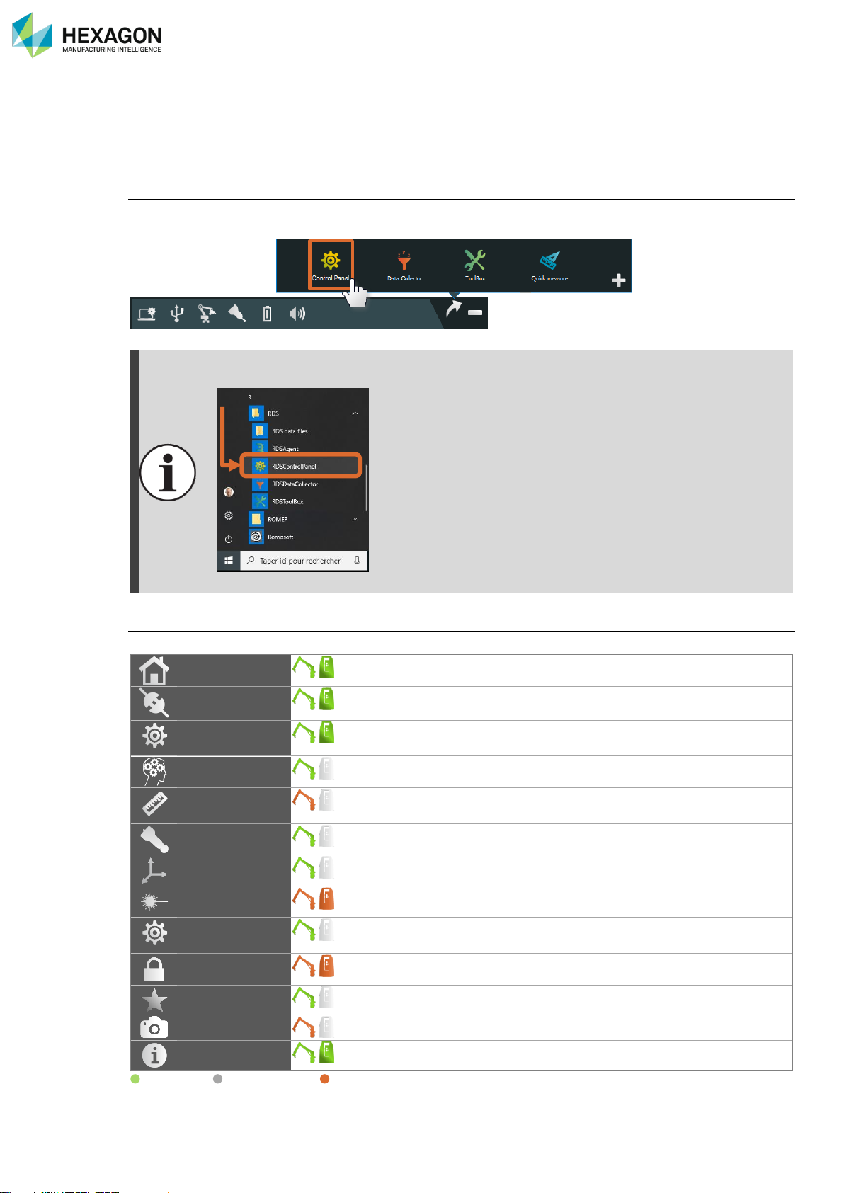
Open RDS Control Panel
To access RDS Control Panel, open the RDS Agent (RDS icon on the notification bar) and select “RDS
Control Panel” in the links.
RDS Control Panel can be also opened from “start menu > Programs > RDS > RDS control
Panel”
Fig. 1 : RDS Control Panel start Menu Windows®
Components of RDS Control Panel
RDS Control Panel is divided in several tabs, available or not according to the connected machine:
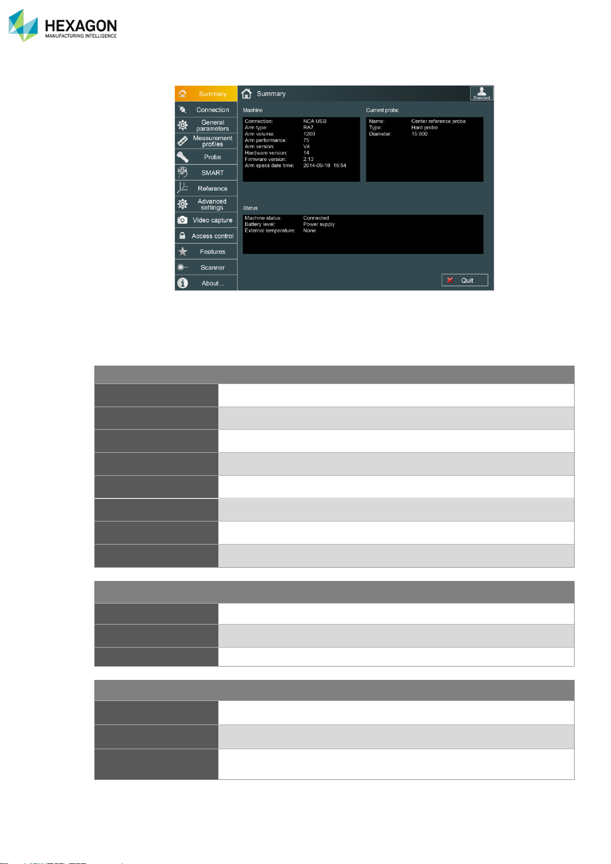
Summary
Shows the status of the machine
Connection
Used to setup the connection with the machine
General
parameters
Language and volume
SMART
Privacy statement and activation of SMART functionalities
Measurement
Profile
Used to activate and manage Arm profiles when available
Probe
Shows current probe and available probes settings
Reference
Allows moving the device keeping the original reference
Scanner
Available when a HEXAGON scanner is connected
Advanced
settings
Various settings on arm for the buttons, mouse…
Access control
Definition of the passwords for the User profiles
Features
Management of the activation codes for protected features
Video capture
(On equipped arms): management of the wrist camera
About
Information on the system.
Available / Not available / Under condition
Page 39
RDS Control Panel
H000002007-RDS User Manual │Version 5.0.0 (2018-09-17) │38
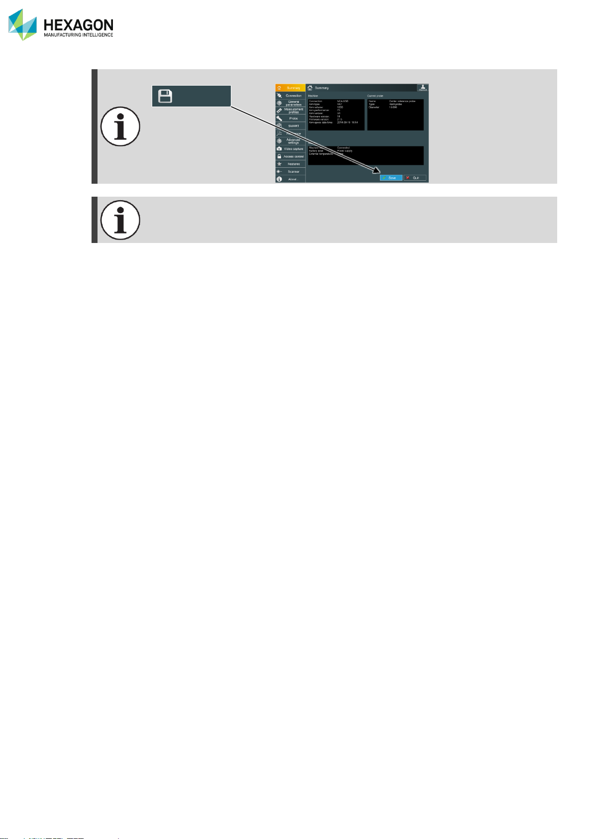
Any modification of the settings needs to be saved: click on
The displayed tabs depend on the connected device: some tabs won’t be displayed when
using a Multi Gage.
Save
Page 40
RDS Control Panel
H000002007-RDS User Manual │Version 5.0.0 (2018-09-17) │39
D.1 SUMMARY
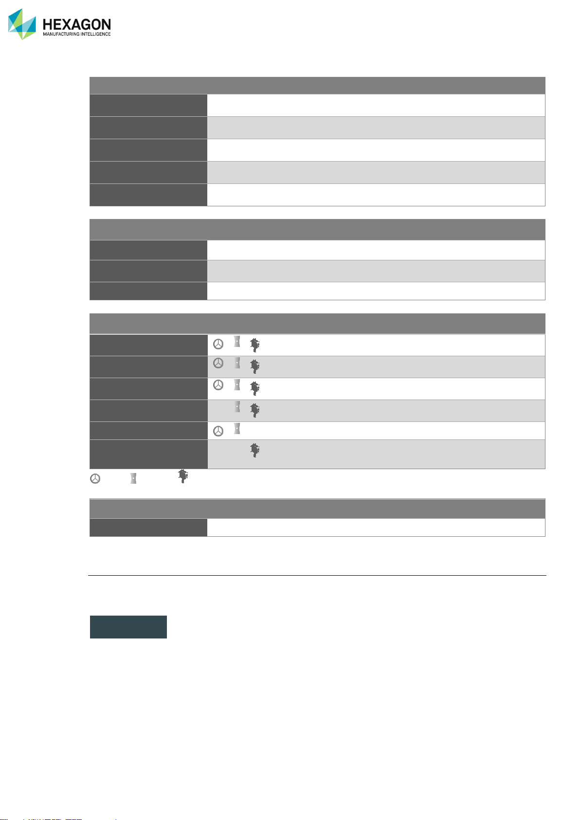
This page shows main information about the connected device:
D.1.1 SUMMARY (ARM)
MACHINE
Connection
Type of system (NCA) connection (USB / WLAN / Wired Ethernet)
Type
Type of arm (Multi Gage/RA7/HA8)
Arm volume
Diameter of the spherical measurement volume in mm
Arm version
Version of the arm
Performance
Performance level of the arm
Hardware version
Version of arm
Firmware version
Version of electronic program in the arm
Armspecs date time
Date and time of last arm Alignment
CURRENT PROBE
Name
Name of the probe (see §C.4.1)
Type
Contact, trigger, scanner, or NC-Tube probe
Diameter
Ball probe diameter
ARM STATUS
Arm Status
Information about connection and status
Battery Level
In % of full level
External Temperature
Gives the ambient temperature measured by the instrument (in °C – an
external temperature sensor must be used)
Page 41
RDS Control Panel
H000002007-RDS User Manual │Version 5.0.0 (2018-09-17) │40
D.1.2 SUMMARY (TRACKER)
MACHINE
Tracker type
Type of tracker and interface
Product name
Tracker model
Serial number
Firmware version
Installed Package Version on the Laser tracker
Compensation
Date and time of last tracker compensation
METEO STATION
Temperature
Humidity
Pressure
CURRENT PROBE
Name
Name of the probe (see §C.4.1)
Type
Reflector, T-Probe, LAS, LAS-XL
Product name
Exact type of probe
Serial number
Identification of the sensor (T-Probe or LAS, LAS-XL).
Diameter
Ball probe diameter
Face (Left/
Top/Back/Right)
Last Alignment result and date for each face
: SMR : T-Probe : LAS
STATUS
Status
Information about connection and status
Create LMF Log file
In order to help diagnosis on a tracker, RDS can generate a log file, which contains all the necessary
information.
Press the button to run the Log file creation:
Once the confirmation message validated, RDS dumps the information and opens a browse window
locating the file: select the new file and send it to your Tracker Service Centre.
Create LMF Log
File
Page 42
RDS Control Panel
H000002007-RDS User Manual │Version 5.0.0 (2018-09-17) │41
D.2 CONNECTION
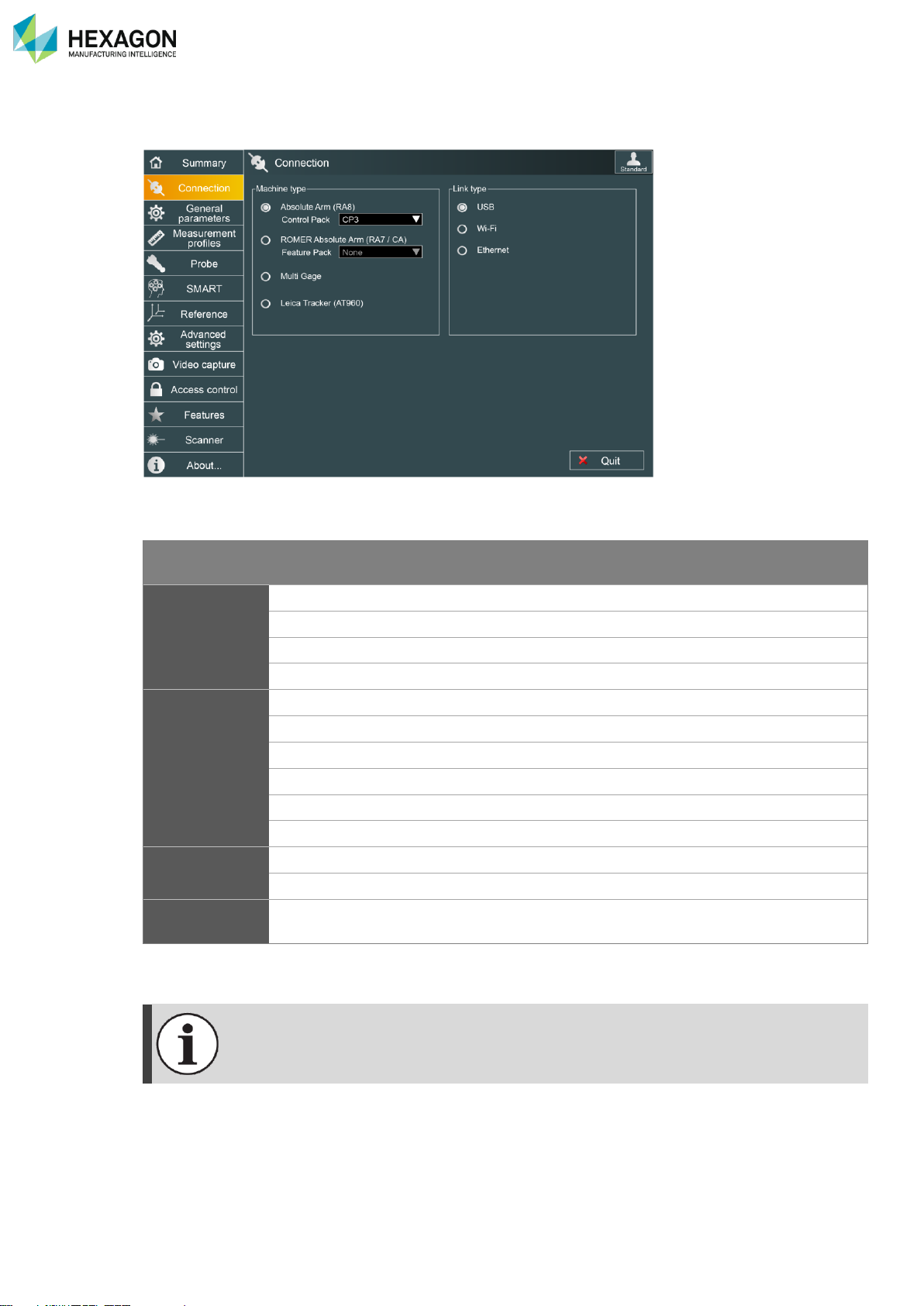
This tab is used to select the type of arm and type of connection.
4 types of machine and 3 types of connections are available:
Connection module
USB
WLAN
Ad-Hoc Access point
Wired Ethernet
Absolute Arm
(RA8)
CP0
✓
CP1
✓
CP2
✓
✓
CP3
✓
✓
✓
ROMER
Absolute Arm
(RA7/CA7)
None
✓
FP1
✓
FP2
✓
✓
FP2+
✓
✓
FP3
✓
✓
FP3+
✓
✓
✓
Multi Gage
✓
WLAN Activation code
✓
✓
Leica Tracker
(AT960)
✓
According to the selected type of connection, additional parameters may be displayed above.
- Please refer to the arm manual (ROMER Absolute arm manual / Multi Gage manual) for
complete description of WLAN connection.
- WLAN selection for Multi Gage needs a valid WLAN (Wi-Fi) feature.
- SSID, Channel, IP address and WEP can be modified. Refer to RDS Toolbox (§ K.2)
Page 43
RDS Control Panel
H000002007-RDS User Manual │Version 5.0.0 (2018-09-17) │42
D.2.1 USB CONNECTION (ARM)
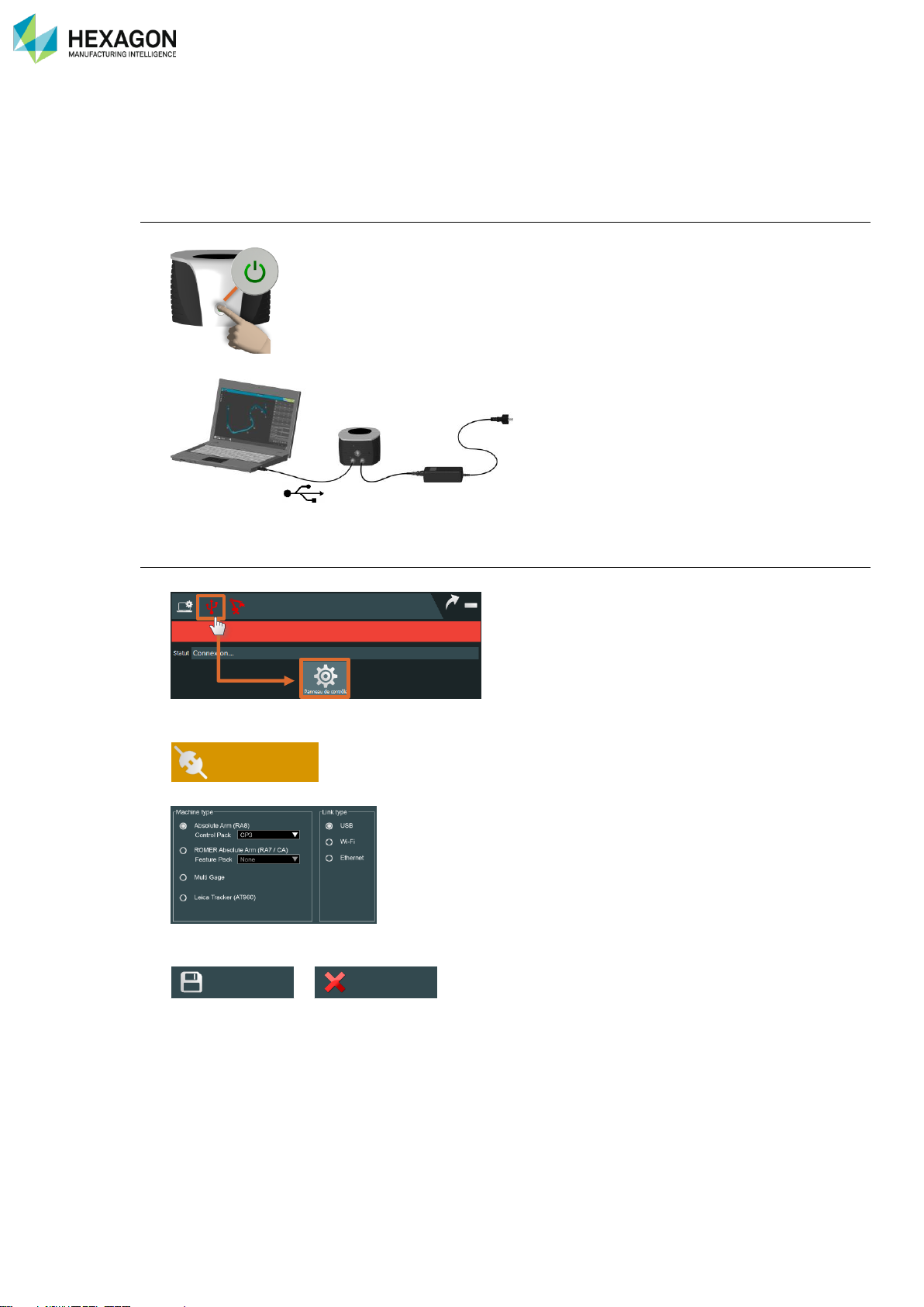
Please follow the instruction below to connect RDS to the arm (ROMER Absolute Arm, Cimcore CA7 Arm,
Multi gage, Infinite and Stinger arms) through USB.
Arm setup
1. Power on the arm.
2. Ensure that the USB cable is correctly connected from the arm to the computer
RDS setup
3. Enter RDS Control Panel
4. Select Connection tab
5. Select arm type and USB type
6. Save the modifications.
>
7. Now RDS automatically connects to the arm.
Connection
Save
Quit
Page 44
RDS Control Panel
H000002007-RDS User Manual │Version 5.0.0 (2018-09-17) │43
D.2.2 WLAN SETTINGS (ARM)
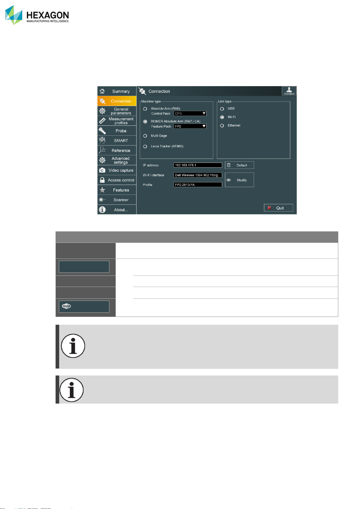
The link type “Wi-Fi” (WLAN) is available only if the appropriate Feature/Control Pack is selected or if
Multi Gage (with a valid activation code) is selected).
When Wi-Fi link type is selected, Wi-Fi settings become available:
Information
Description
IP address
Area to enter the IP address of the machine
FP2
/
FP3
only
Changes back the IP address to the default one according to the machine.
Wi-Fi interface
Displays the selected Wi-Fi interface
Profile
Displays the selected Wi-Fi Windows® profile
Opens the configuration window to select the Wi-Fi interface and the
Machine network.
Default IP address:
Feature Pack
IP address
FP2
192.168.0.3
FP2+ / CP2
192.168.178.1
FP3
192.168.178.199
FP3+ / CP3
192.168.178.1
Wi-Fi connection to FP2 and FP3 (Ad-Hoc mode) under Windows10 require extended
settings of the Wi-Fi device. Most computers cannot provide such settings.
Hi-Level external USB-Wi-Fi adapters may be used to connect FP2 / FP3 to Windows10.
Default
Modify
Page 45
RDS Control Panel
H000002007-RDS User Manual │Version 5.0.0 (2018-09-17) │44
Wi-Fi Network connection (FP2 / FP3)
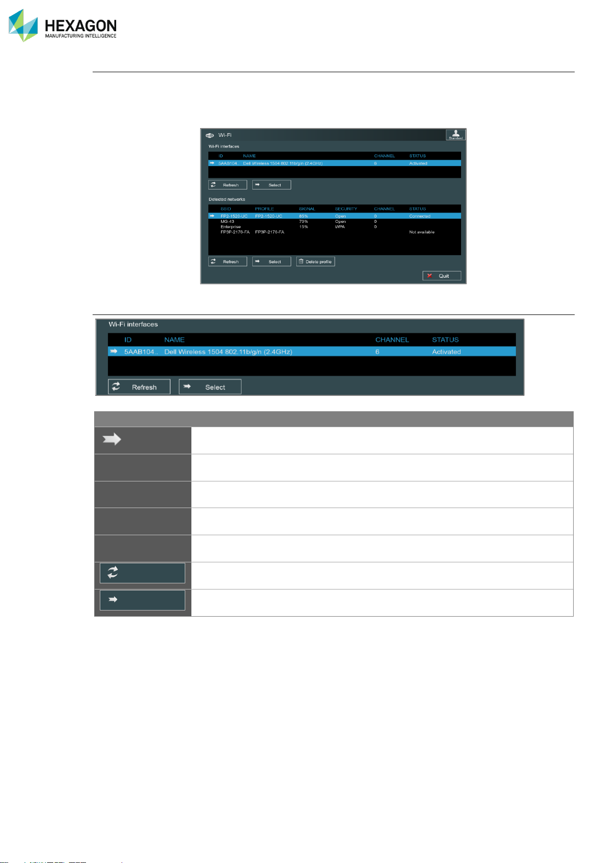
To connect the arm Wi-Fi network, it is not necessary to enter Windows® Wi-Fi configuration: RDS can
manage itself the Absolute Arms and Multi Gages Wi-Fi networks and profiles:
Select “Modify” button, to access to the following window:
Wi-Fi interfaces
Information
Description
Value
Selected interface
Name
Displays all available Wi-Fi interface devices
ID
Identification code of the interface
Channel
Wi-Fi channel currently used by the interface.
Status
Displays the connection status of each interface
Connected
Disconnected
Button to refresh the list of available interfaces
Button to validate the choice of the selected interface
Refresh
Select
Page 46
RDS Control Panel
H000002007-RDS User Manual │Version 5.0.0 (2018-09-17) │45
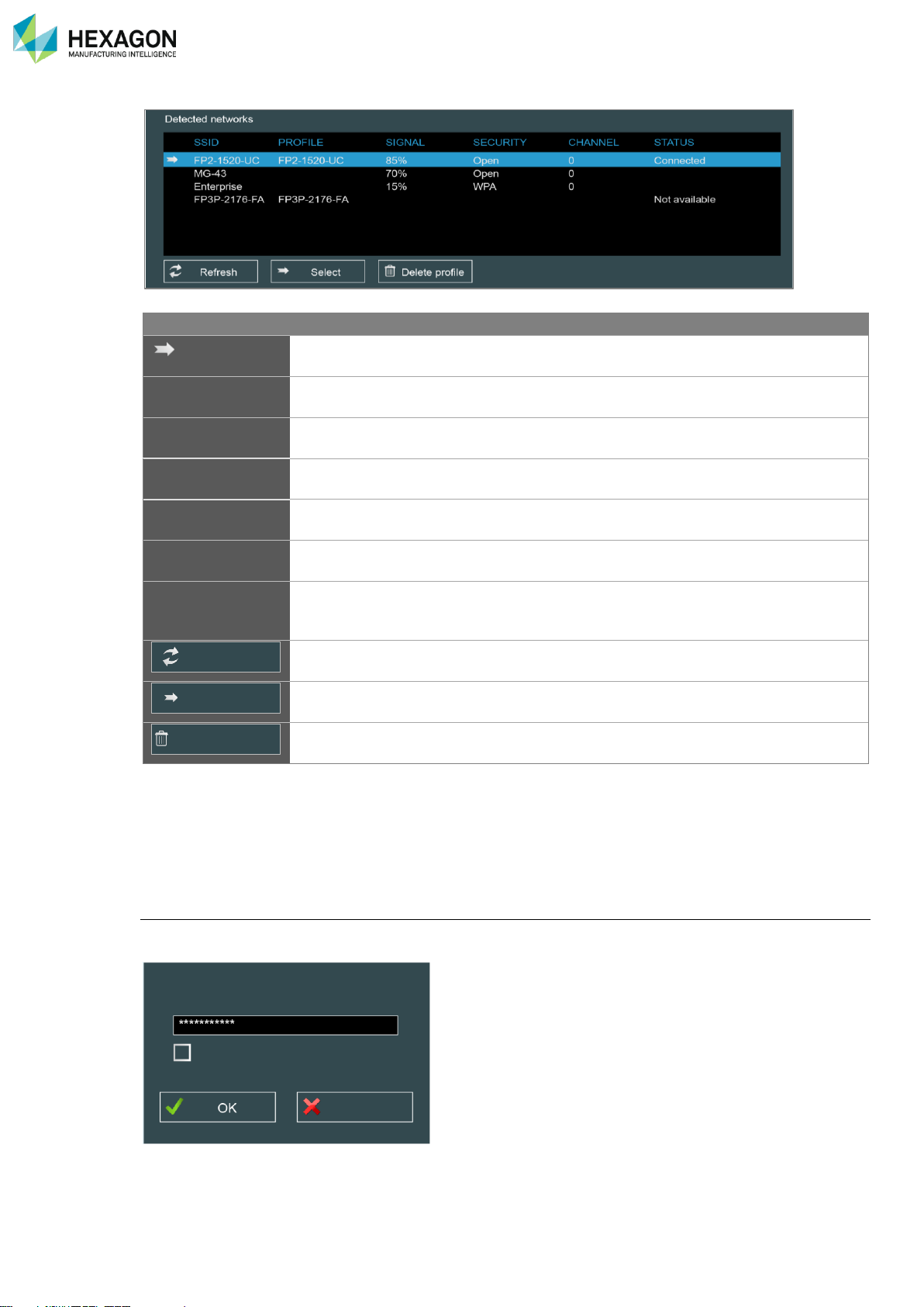
Information
Description
Value
Selected network
SSID
Displays all available Ad-Hoc Wi-Fi networks
Profile
Shows the associated Windows® Wi-Fi profile when
existing
Signal
Strength of the Wi-Fi signal
Percentage
Security
Type of Wi-Fi security
Open / None
WEP
Channel
Wi-Fi channel currently used by the network.
Status
Displays the connection status of each network
Connected
Disconnected
Not Available
Button to refresh the list of available networks
Button to validate the choice of the selected network
Button to delete the existing profile
If the computer has several Wi-Fi devices, choose the one that must be used to connect to the arm and
click on “Select”.
RDS checks then scans all the Wi-Fi networks recognized as an arm network and displays them in the list.
Select the one fitting to the feature pack of the arm or to the Multi Gage and click on “Select”: RDS
automatically creates a profile in Windows® and connects the computer to the selected network.
Wep key
According to the settings of the Wi-Fi network, a Wep key may be requested for the first connection: enter
the key in the request window.
Refresh
Select
Delete profile
Network key
Cancel
Show plain password
Page 47
RDS Control Panel
H000002007-RDS User Manual │Version 5.0.0 (2018-09-17) │46
D.2.3 COMPUTER SETUP FOR WIRELESS CONNECTION (ARM)
The Wi-Fi chipset used for the wireless connection should be exclusively dedicated to it.
Please read in appendix the recommended settings for the Wi-Fi chipset.
The following operation is necessary before trying to connect RDS to any arm through Wi-Fi
Computer setup
1. Switch on the computer’s Wi-Fi adapter
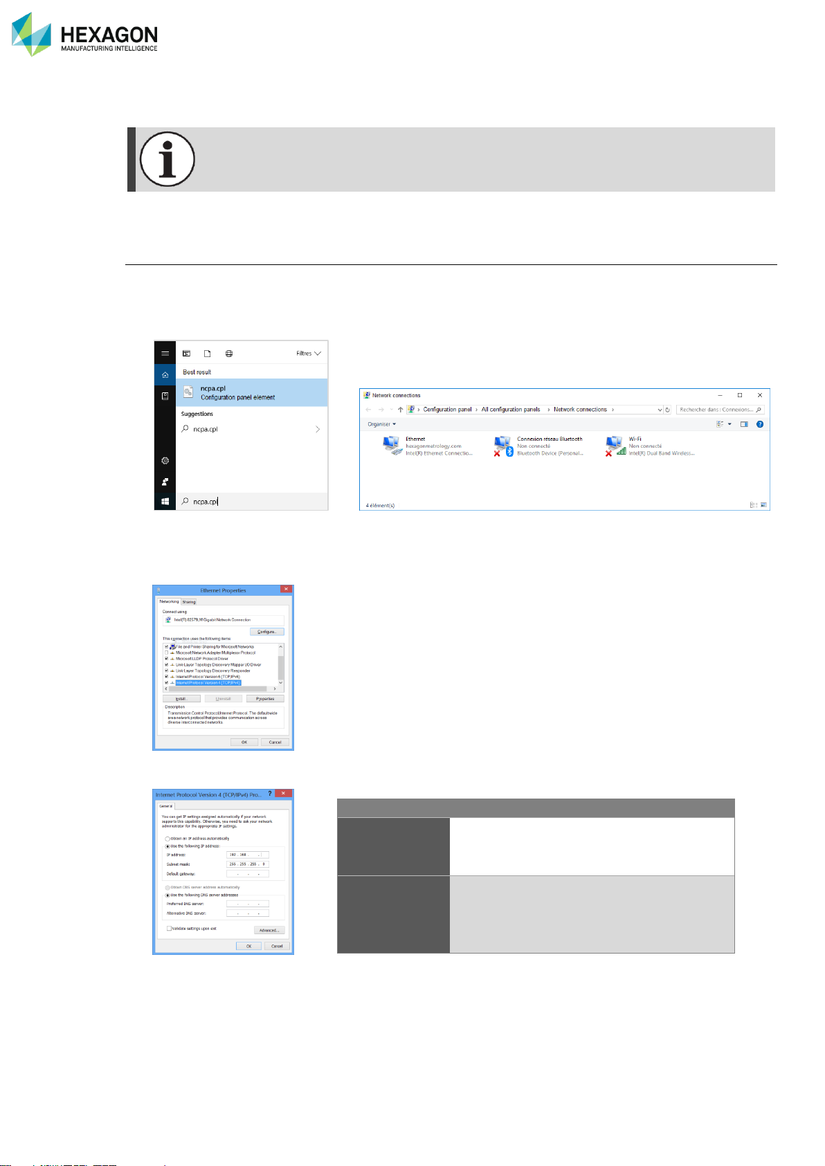
2. Access the Search function on the right side of the screen in Windows10® (“Start menu” for Windows7®)
> type in “ncpa.cpl” to access the network connection settings.
3. Right-click on “Wireless Network Connection” and select “Properties”:
4. Select Internet Protocol (TCP/IPv4), then “Properties”
5. Use the following IP address and subnet mask then OK
IP address
Subnet mask
Multi Gage
FP2
FP3
192.168.0.1
255.255.255.0
FP2+
FP3+
CP2
CP3
“Obtain an IP address automatically”
Page 48
RDS Control Panel
H000002007-RDS User Manual │Version 5.0.0 (2018-09-17) │47
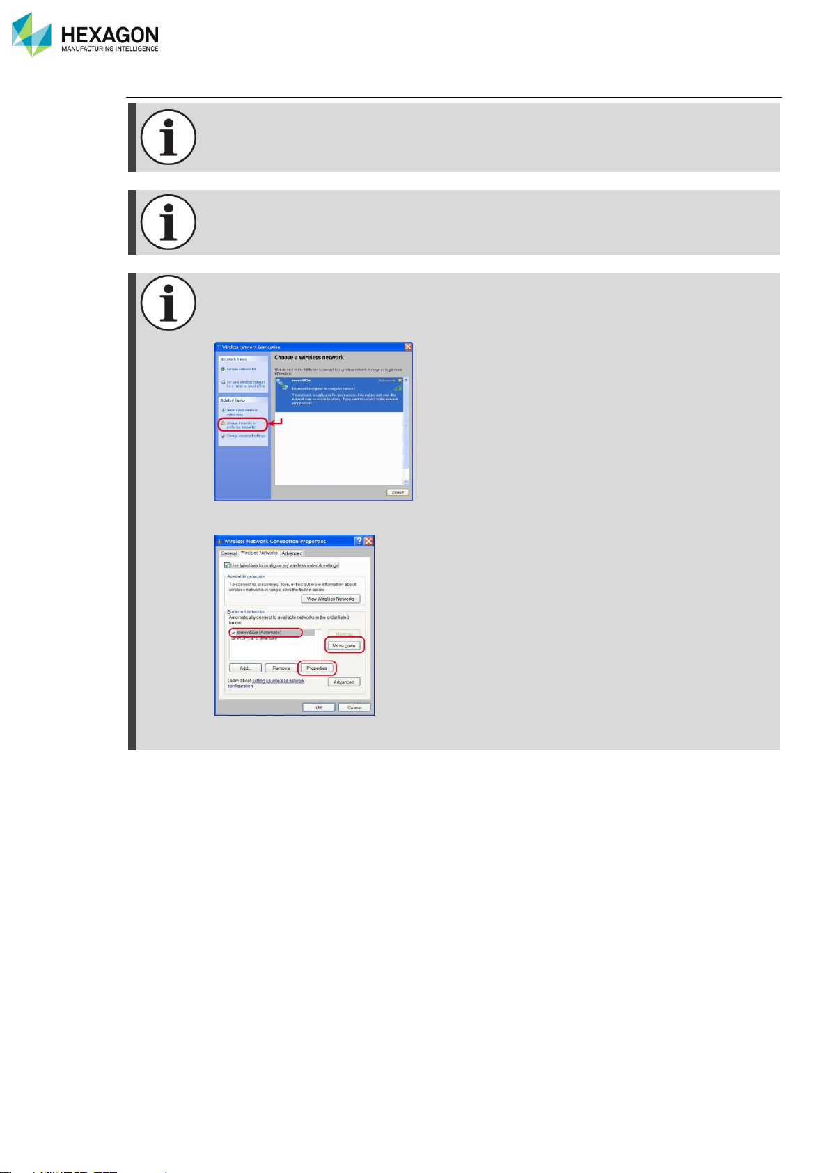
Third party setup software and preferred order of networks
Some computers may use by default a specific management software for Wi-Fi instead of
Windows®. Such management software may not be able to communicate with ROMER WiFi. In such a case, it is necessary to deactivate it, and to use Windows® management for
the Wi-Fi
The Wi-Fi of the computer may be managed by specific software for the device. In this case,
refer to its manual to connect to the arm network and setup the IP address.
If the Wi-Fi of the computer manages preferred order for networks, make sure that the arm
network is at the top of the list.
Ex: if Windows® manages the Wi-Fi, in the wireless configuration, select “change the order
of preferred networks”
You access then to the following window: select then the arm network and click on “Move
up” until it becomes at the top of the list.
Here, using “Properties”, you can also switch the “T-UN-FF” network as automatic
connection if it is not
Page 49
RDS Control Panel
H000002007-RDS User Manual │Version 5.0.0 (2018-09-17) │48
D.2.4 WIRELESS CONNECTION (ARM)
Please follow the instruction below to connect RDS to the arm through Wi-Fi.
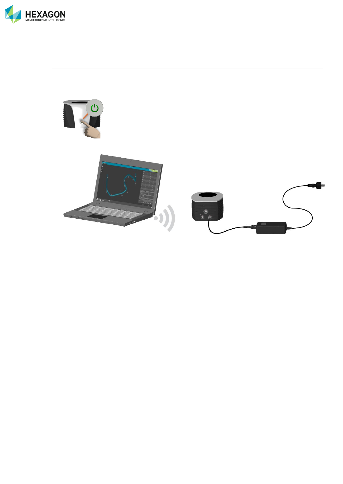
Arm setup
1. Make sure that the Mobility Pack or higher is installed on the arm or that the Wi-Fi feature code for the
Multi Gage is installed in RDS.
2. Power on the arm.
3. Ensure that the USB cable is disconnected from the arm to the computer and that the Wi-Fi light on the
front of the arm is on.
Computer setup
4. Setup the TCP/IP V4 address of the Wi-Fi interface of the computer according to the Feature Pack (see
previous §)
2
Page 50
RDS Control Panel
H000002007-RDS User Manual │Version 5.0.0 (2018-09-17) │49
RDS setup
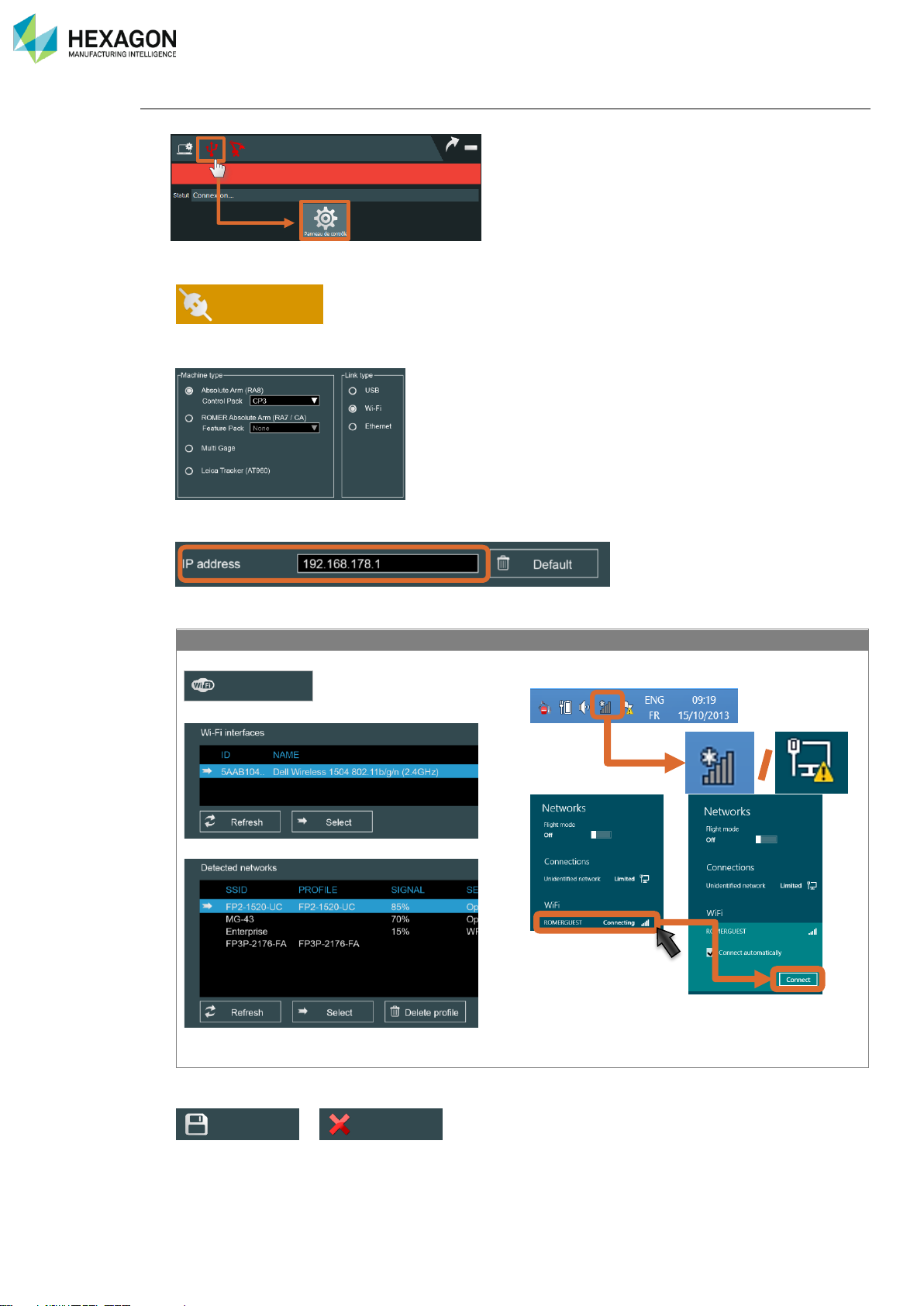
5. Enter RDS Control Panel
6. Select Connection tab
7. Select the type of Instrument, type of Pack (Control / Feature, for the Absolute Arm) and “Wi-Fi”
8. If the Pack address has been modified, enter the TCP/IP address.
9. Connect the network
FP2 / FP3
CP2 / CP3 / FP2+ / FP3+
Click on “Modify”
Choose the Wi-Fi interface and “Select”
Choose the Feature Pack SSID and “Select”
Close the Wi-Fi window and
Display the available wireless networks and
connect the Feature Pack
10. Save the modifications.
>
11. Now RDS automatically connects to the arm.
Modify
Connection
Save
Quit
Page 51
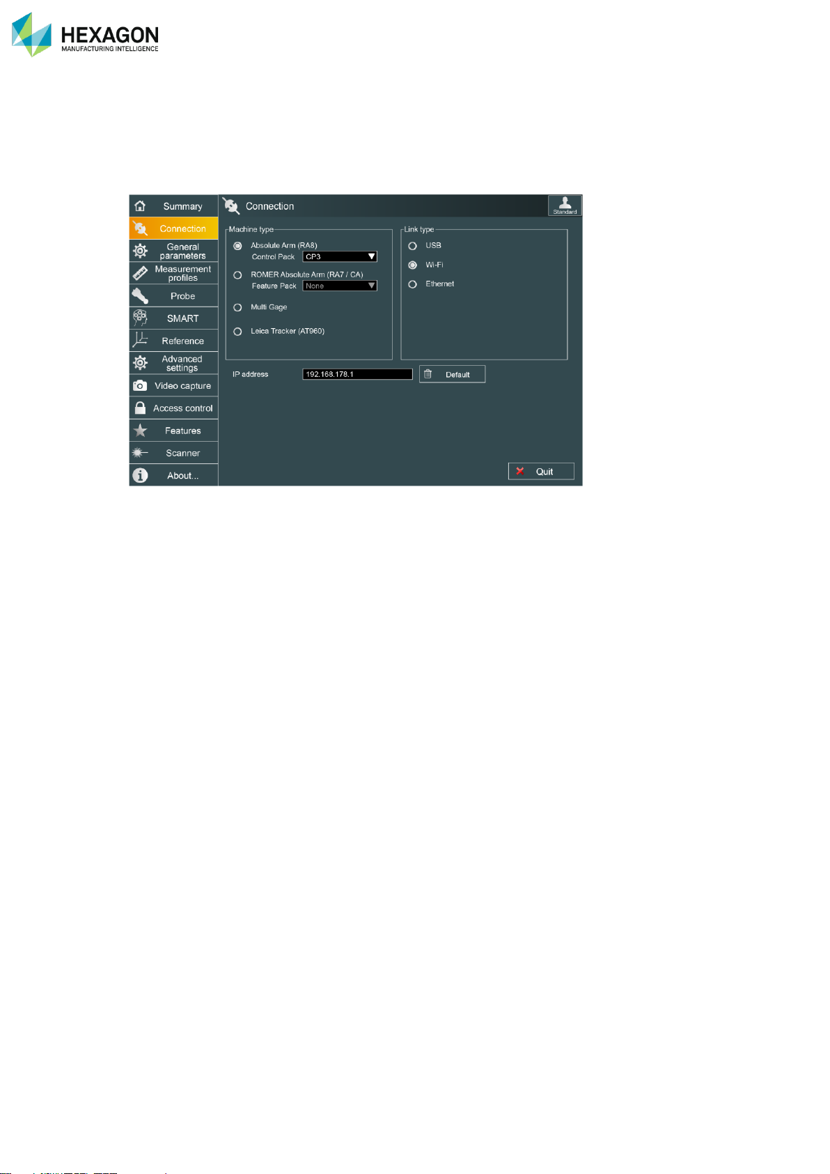
RDS Control Panel
H000002007-RDS User Manual │Version 5.0.0 (2018-09-17) │50
D.2.5 RSX WIRELESS CONNECTION (ARM)
When the Absolute Arm SI (integrated scanner) is equipped with a Pack “Wireless Scanning Pack” (CP3 /
FP3 or FP3+), the scanner can be connected through the wireless connection of the arm: no specific
operation is needed, once the arm is connected with the Wireless Scanning Pack, the scanner connection
doesn’t need any cable.
Page 52
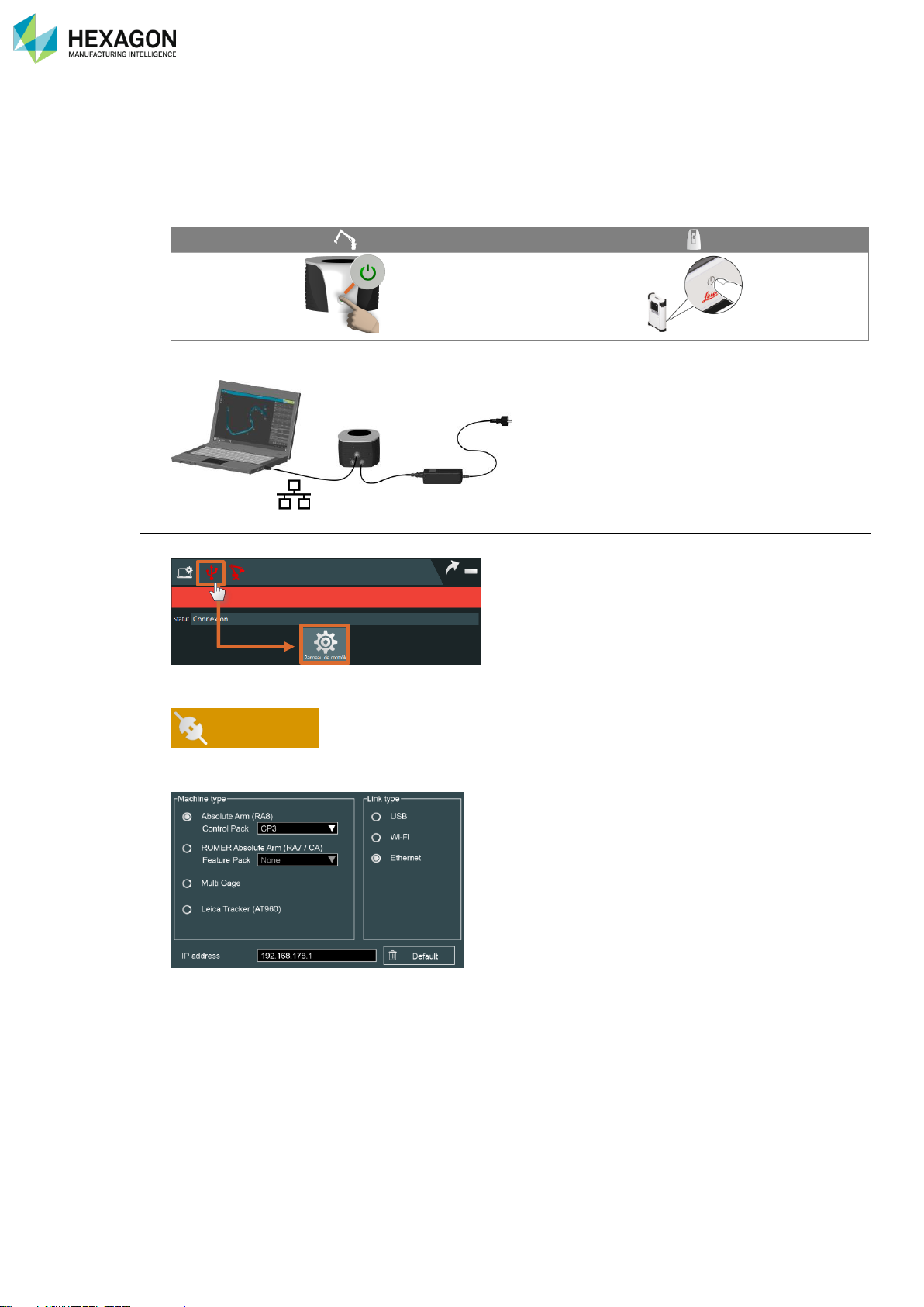
RDS Control Panel
H000002007-RDS User Manual │Version 5.0.0 (2018-09-17) │51
D.2.6 WIRED ETHERNET CONNECTION (ARM / TRACKER)
Please follow the instruction below to connect RDS to the arm (Absolute Arm or Cimcore CA7 Arm with
FP3+ / CP3) or the tracker through wired Ethernet.
Machine setup
1. Power on the machine.
2. Ensure that the Ethernet cable is correctly connected from the machine to the computer
RDS setup
3. Enter RDS Control Panel
4. Select Connection tab
5. Select the type of machine and Wired Ethernet link type
Connection
Page 53
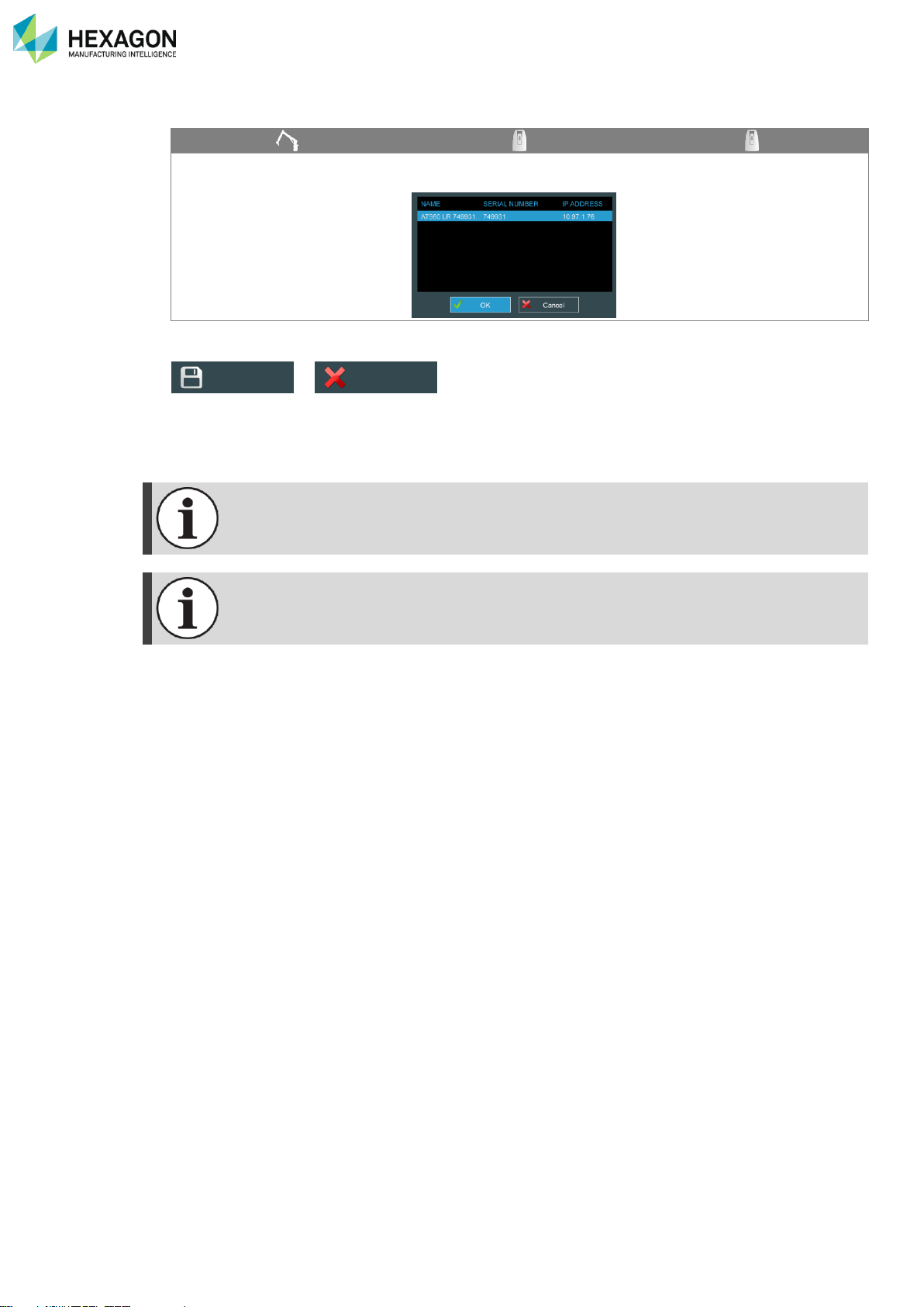
RDS Control Panel
H000002007-RDS User Manual │Version 5.0.0 (2018-09-17) │52
6. Use the default IP address or Set it up:
Enter the IP address.
Click on “Discover”, select the
tracker to connect and OK.
Enter manually the IP address
7. Save the modifications.
>
8. Now RDS automatically connects to the arm or the tracker.
The tracker is connected only when a measurement software connects its RDS plug-in.
The « Default » button permits to get back the original default address.
Save
Quit
Page 54
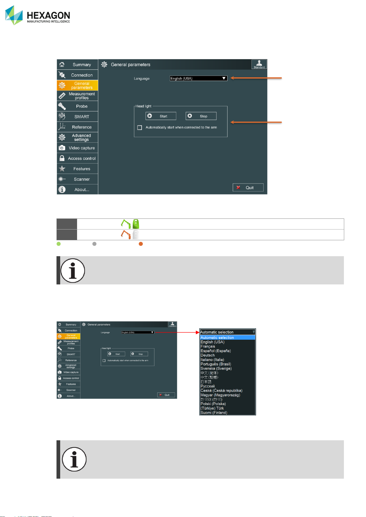
RDS Control Panel
H000002007-RDS User Manual │Version 5.0.0 (2018-09-17) │53
D.3 GENERAL PARAMETERS
General parameters contain the volume of the arm, the language selection and the activation of the wrist
headlight (only for equipped arms).
1
Language
Selection of the UI language
2
Head light
(On equipped arms): activate the light
Available / Not available / Under condition
The sound level can be set directly on the RDS Agent
D.3.1 LANGUAGE
By default, RDS automatically select the language depending on the language of the operation system.
Select the wanted language, then save (validate the message asking for restart).
Once saved the change of language, RDS needs to be restarted:
For RDS Control Panel or RDS Data Collector or RDS Quick Measure, simply close and
open again.
For all other tools (RDS Service, RDS Toolbox…), restart RDS Service itself or restart the
computer.
1
2
Page 55
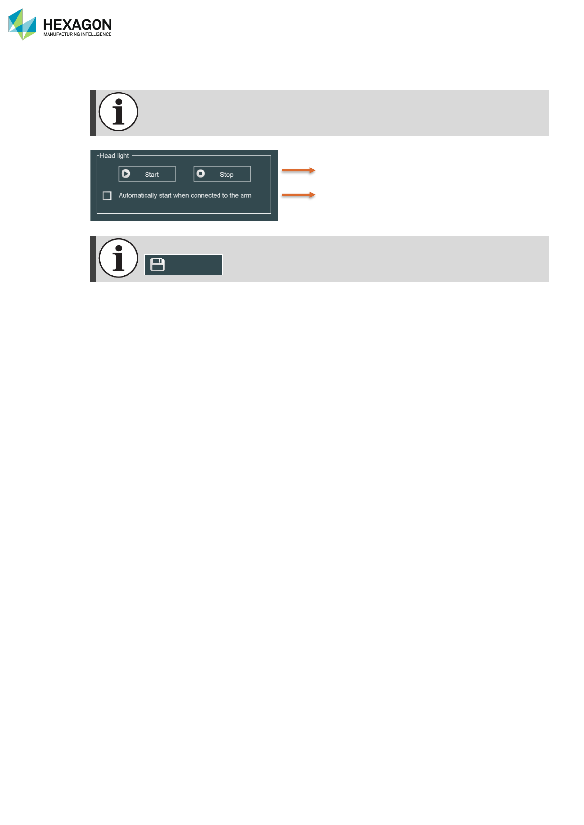
RDS Control Panel
H000002007-RDS User Manual │Version 5.0.0 (2018-09-17) │54
D.3.2 HEAD LIGHT (FOR EQUIPPED ARMS)
This tab is displayed only for a 6 axes 75XX (V1-V2-V3) and 73xx V3 series ROMER Absolute
arm
Starts-Stops the head light on the F axis
Activate-deactivate the auto start
Nb: do not forget to save configuration after modification.
Save
Page 56
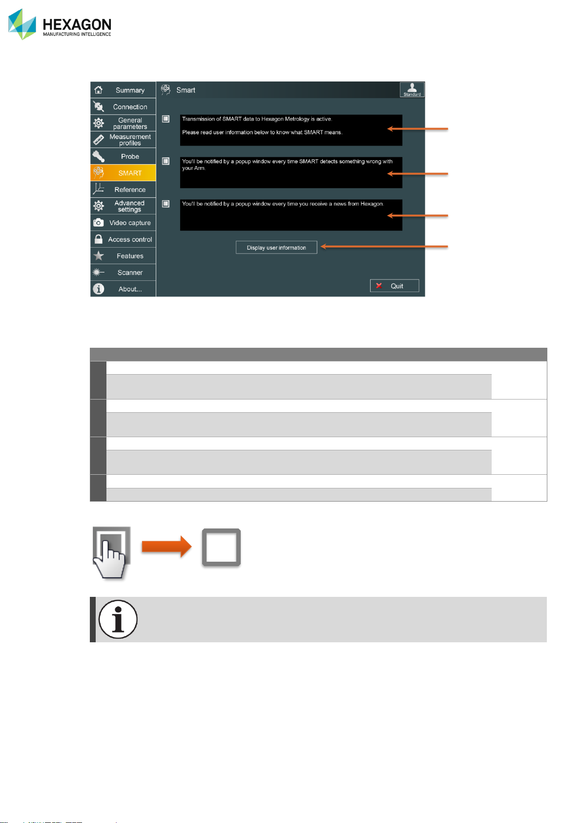
RDS Control Panel
H000002007-RDS User Manual │Version 5.0.0 (2018-09-17) │55
D.4 SMART (ARMS)
The SMART tab in RDS control Panel gives access to the activation of the SMART automatic components,
as well as the user information.
Default
1
Activation of the transmission of SMART data:
Activated
when activated, RDS will automatically send SMART data to the HEXAGON
Server.
2
Activation of the SMART alerts:
Activated
when activated, RDS will display a popup notification when a SMART alert is
detected, or when a news is received.
3
Activation of the Hexagon Manufacturing Intelligence news:
Activated
when activated, RDS will be able to provide news regarding the product, new
versions...
4
Display user information
English
Display the official user information as during the installation of RDS.
To activate or deactivate an option, simply click on the check box:
For all other information regarding RDS SMART, refer to chapter J. SMART
1 2 3
4
Page 57
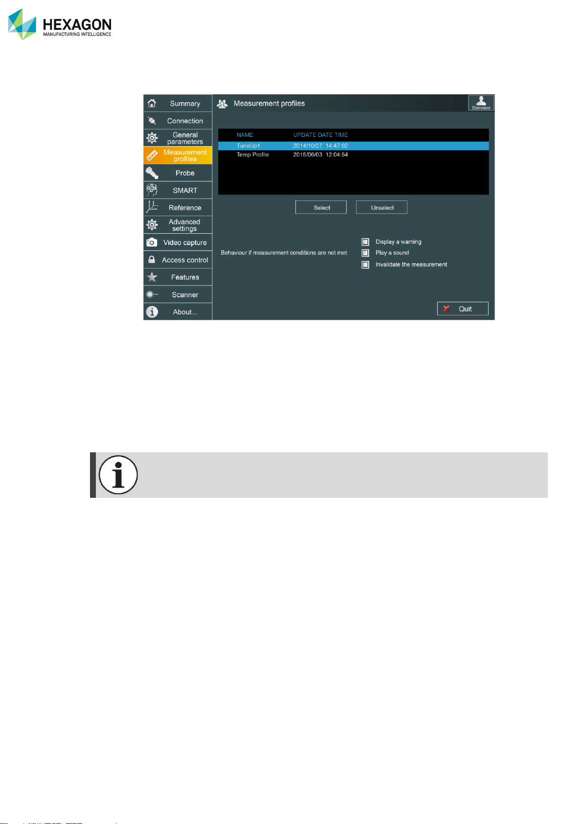
RDS Control Panel
H000002007-RDS User Manual │Version 5.0.0 (2018-09-17) │56
D.5 MEASUREMENT PROFILES (ARMS)
With RDS, one or several profiles can be created to manage specific uses of the arm.
These profiles then appear in this tab and can be activated.
It is possible to specify how must react RDS when the user measures out of the restrictions.
• Display a warning: display a message at the centre of the screen
• Play a sound: a beep is emitted
• Invalidate the measurement: the point is not accepted.
Contact your Hexagon agent for more information about the profiles.
Page 58
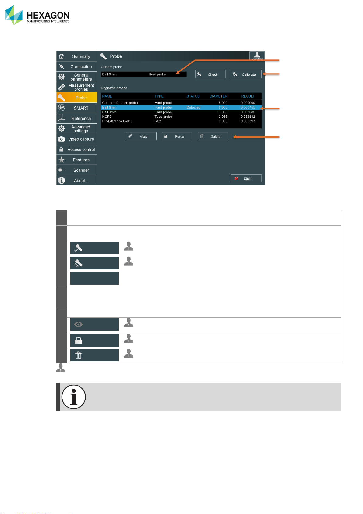
RDS Control Panel
H000002007-RDS User Manual │Version 5.0.0 (2018-09-17) │57
D.6 PROBE (ARMS)
This tab displays the current installed probe and allows selecting it manually.
1
Current probe
Shows the name and type of the current mounted probe on the arm
(detected or forced).
2
Action buttons
Shortcuts to RDS Data Collector: automatically opens and run verification
or Alignment scripts.
Runs a Probing Quick Check script through RDS Data Collector.
Runs the current probe Alignment through RDS Data Collector (different
available methods are proposed).
(HA8-7axes only) switches Centred probe <> Scanner (or Offset probe)
3
Registered
probes
Displays the list of all the probes aligned and saved in the memory of the
arm. Selected probe is highlighted in blue.
(see next chapter for more details)
4
Action buttons
Management of the selected probe in the list. (see after)
Displays the characteristics of the selected probe.
Gives access to edit it.
Force the selected probe as Current probe.
Remove the selected probe from the memory of the arm.
: at least advanced user.
When using “Force probe selection”, make sure that the selected probe is the one installed
on the arm
Check
Calibrate
Switch selection
View
Force
Delete
2 3 4
1
Page 59
RDS Control Panel
H000002007-RDS User Manual │Version 5.0.0 (2018-09-17) │58
D.6.1 PROBE LIST AND SELECTION
By default, the probe is automatically recognized and selected when plugged on the arm.
It is possible to deactivate and select manually the probe.
NAME
TYPE
STATUS
DIAMETER
RESULT
Centre reference probe
Hard probe
15.000
0.000000
Ball 6mm
Hard probe
Detected
6.000
0.000755
Ball 3mm
Hard probe
3.000
0.003585
NCP2
Tube probe
0.086
0.086842
HP-L-8.9 15-03-016
RSx 0.000
0.000393
In the sheet above, are shown all available probes, with all corresponding information.
Information
Description
Displayed value
Name
Name of the probe entered when Aligned
name
Type
Show the type of probe (contact, trigger, scanner,
Tube probe)
type
Status
Current status (null / Detected / Forced)
status
Diameter
Diameter of the ball probe
Diameter in selected unit
Calculation
result
Result of the last Alignment of the selected probe
= “Not Aligned” when probe is not
Aligned
Page 60
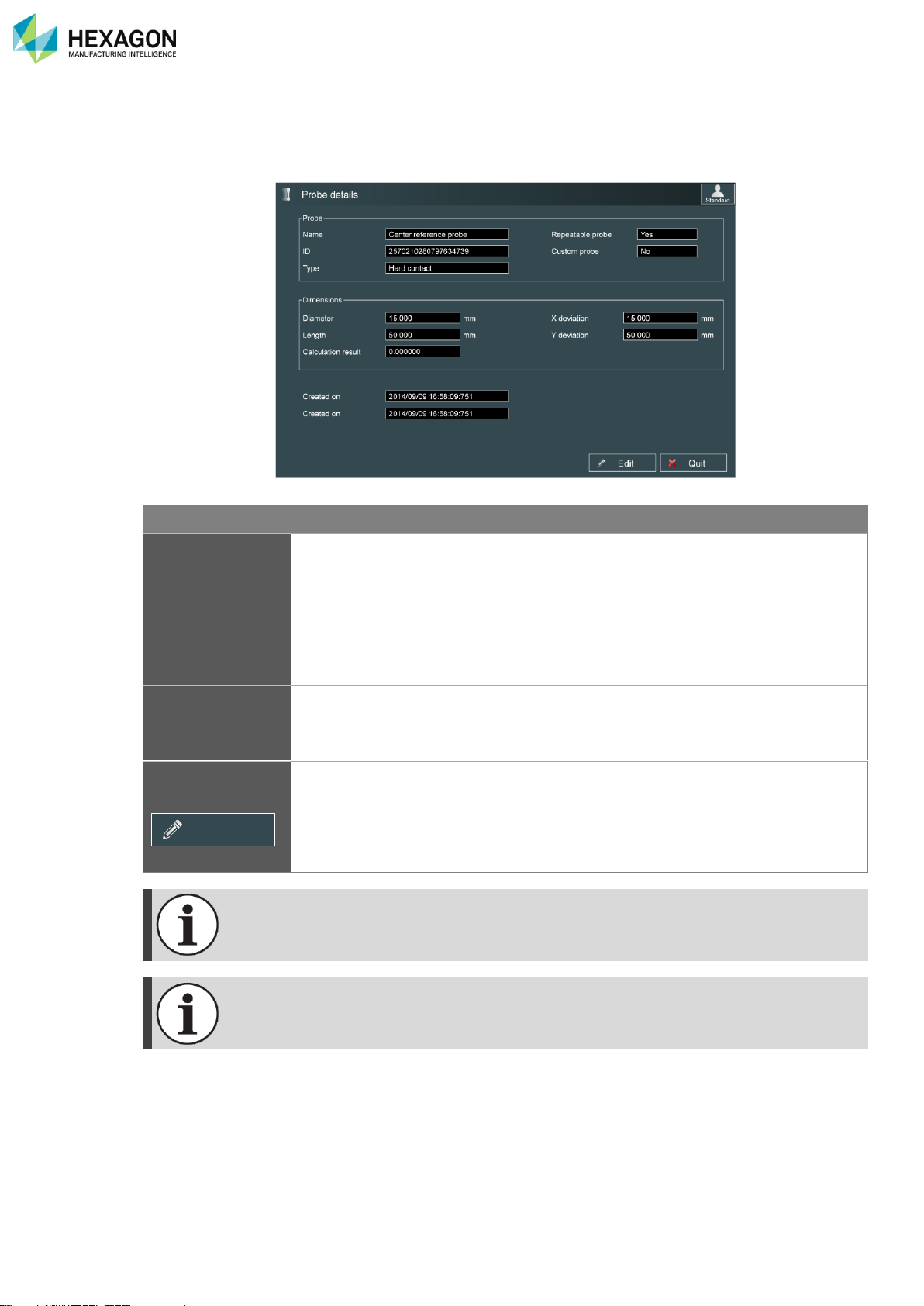
RDS Control Panel
H000002007-RDS User Manual │Version 5.0.0 (2018-09-17) │59
D.6.2 VIEW SELECTED PROBE (ADVANCED USER)
Once a probe is selected and settings saved, it is possible to edit the parameters of the probe:
When the operator changes simply the end sensor of the probe, this is not automatically
detected, but probe Alignment is necessary: enter “View” button and edit the new diameter.
Only the installed probe can be modified. Once the name or diameter are modified, new
values are automatically saved in the probe memory.
Item
Description
Values
ID, Name, Type,
Diameter,
calculation result
All same values as before
Custom Probe
Defines if the probe is specific or standard
Yes / No
Repeatable probe
Shows if the probe is repeatable (TKJ probe) or not and then
needs realignment each time it is mounted
Yes / No
X dev, Y dev,
Length
X, Y and Z dimension according to TKJ axis
Value in mm
“Created on”
Date of the first installation of the probe on the arm.
“Updated on”
date of last modification (name or diameter change) or last
Alignment
Use this button to modify either the name of the Probe, either
the diameter, or the length (approx.), in case of change of the
stylus.
Edit
Page 61

RDS Control Panel
H000002007-RDS User Manual │Version 5.0.0 (2018-09-17) │60
How to … Edit the settings of a probe
1. Connect the arm to RDS (USB or Wi-Fi)
2. Mount the probe to edit
3. Open RDS Control Panel, Tab “Probes”
4. Select the probe to edit
5. Click on “View”
6. Click on “Edit”
7. Modify the desired value(s)
8. Click on “Save”
9. Validate the warning message
10. Proceed to the probe Alignment
Page 62
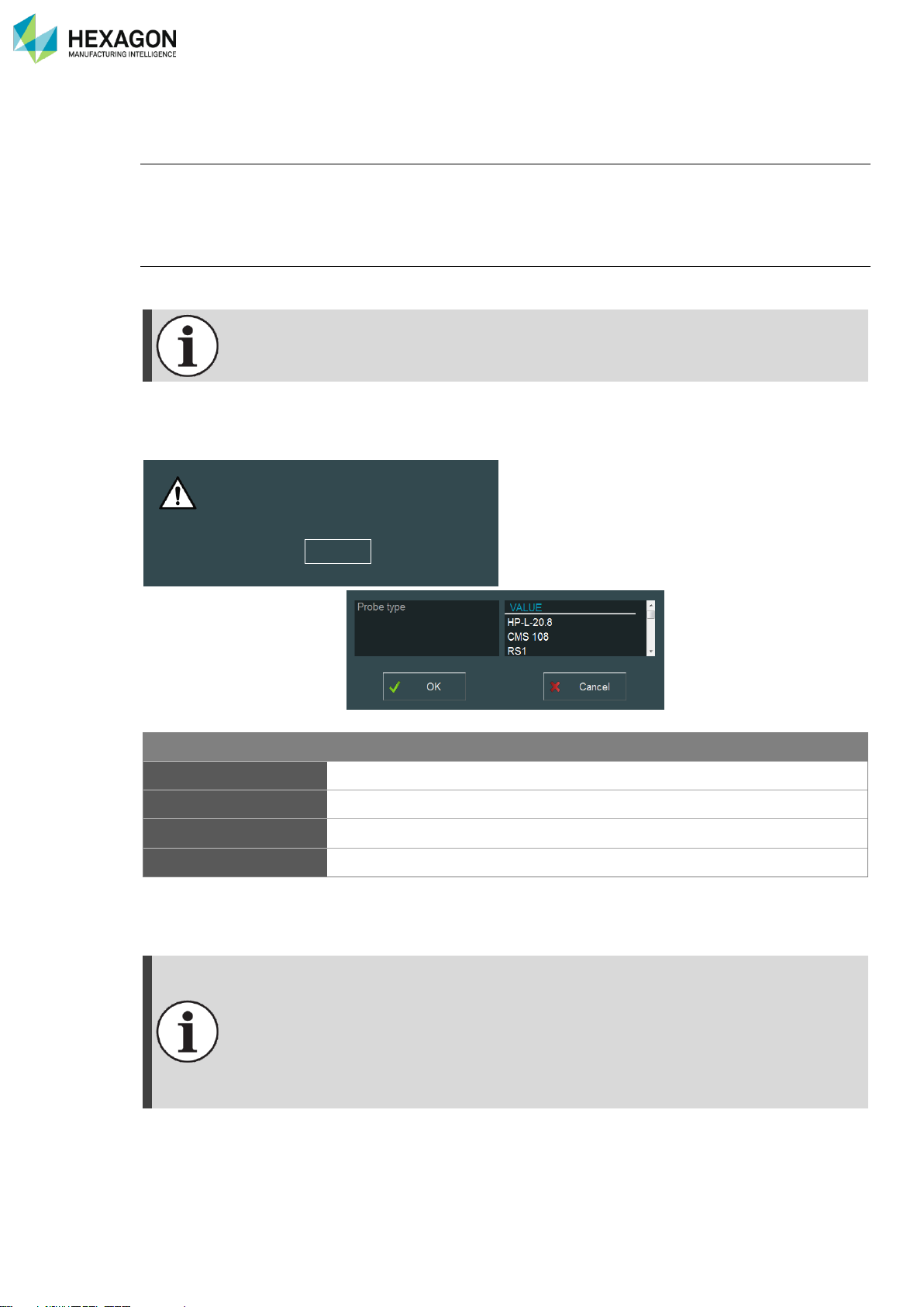
RDS Control Panel
H000002007-RDS User Manual │Version 5.0.0 (2018-09-17) │61
D.6.3 ADDING A NEW PROBE
Contact or NC-Tube probe
If a new probe (that is not in the probes list) is mounted on the arm, RDS automatically detects it and asks
user to Align it. Then it runs “RDS data collector” to Align the new probe. Only after that, the new probe is
displayed in the list.
Legacy Scanners
Legacy types of scanners have the same ID. It means that only one scanner can be used at time on one
arm.
HP-L-8.9 and RS5 scanners have individual IDs. They are managed the same way as contact
probes.
If no scanner exists in the list of probes, as soon as a scanner is mounted on the arm, RDS notifies the
user that a scanner was detected and asks for the type of scanner
Type
Description
HP-L-20.8
HEXAGON HP-L-20.8T Laser scanner, managed by RDS
CMS108
CMS 108 Laser scanner, managed by RDS
External Scanner
Any 3rd party scanner (such as Perceptron, Kreon)
RS2 / RS3 / RS4
RS2 / RS3 / RS4 ROMER Laser Scanner (SI arm)
Once this is informed, the scanner appears in the list of probes. In case of HP-L, CMS or RSx, RDS
connects it and asks for scanner qualification.
RDS can manage only one legacy scanner at a time. If a scanner already exists in the list of
probes, it is no more possible to add another one.
To add a new one, it is then, necessary to delete the existing one in the list.
If a scanner (type1) already exists in the list, if another type (type 2) of scanner is plugged,
then RDS will recognize it as the existing one and will try to connect it.
Ex: A CMS is present in the list of probes. If we mount a Perceptron on the arm, RDS
recognizes it as a CMS and tries to connect it as a CMS, unsuccessfully.
An unidentified scanner has been detected.
Please choose its type in next screen.
Yes
Page 63
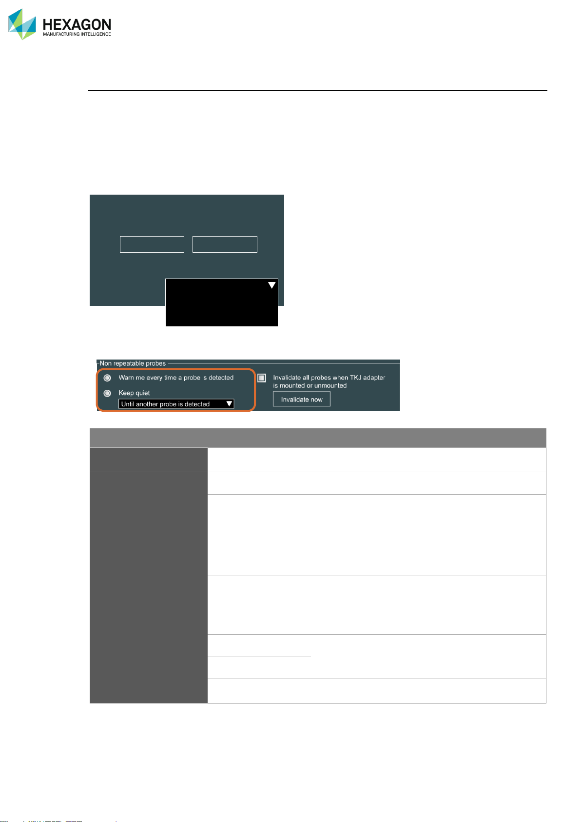
RDS Control Panel
H000002007-RDS User Manual │Version 5.0.0 (2018-09-17) │62
D.6.4 NON-REPEATABLE PROBES (ABSOLUTE 71 SERIES)
Threaded probes
Some probes present the particularity not to be repeatable:
• Probe kit: the probe can be dismounted, to change the length, or configuration
• Thread probe.
Such probes, as they are assembled or mounted through a screw, are not repeatable.
It means that they must be realigned each time they are used. To prevent the operator to forget to realign,
these types of probes are programmed as “Non-repeatable” probes and each time they are plugged on the
arm, RDS asked for realignment:
• For the non-repeatable probes, specific parameters are automatically displayed in Control Panel probe
tab:
Item
Description
Warn me every time a
probe is detected
(default – recommended): each time a non-repeatable probe is connected on
the arm, RDS remind the user to do a probe Alignment.
Keep quiet
RDS will skip the warning:
Until another probe is
detected
If the probe is dismounted from the arm, then
mounted again, no message will appear when
mounting again the same probe, even if it is a nonrepeatable probe.
If another probe is mounted, then RDS will warn
again when the non-repeatable probe will be
mounted.
Until another arm is
connected
Even if another probe is mounted, then the nonrepeatable probe again, RDS will not warn.
Only once another arm is connected, then again, the
arm with the non-repeatable probe, then RDS warn
again
For 1 day
RDS will not warn in any condition for 1 day or 1
week.
For 1 week
indefinitely
The warning functionality is deactivated. (not
recommended)
You may need to align the probe.
Do you want to align it now?
Warn me every time a probe is detected
Keep quiet
Align Continue
Until another probe is selected
Until another arm is connected
For 1 day
For 1 week
Indefinitely
Page 64
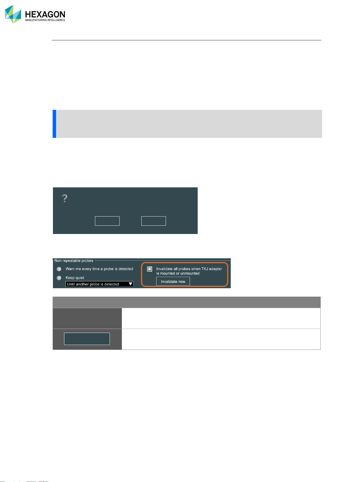
RDS Control Panel
H000002007-RDS User Manual │Version 5.0.0 (2018-09-17) │63
TJK probe adapter management:
For the arms on which the probe is threaded (no TKJ connection neither M27 Probe nut) such as 71xx
series arms, the probes don’t have the same repeatability as TKJ probes or M27 probes. Moreover, some
probes, are available only with TKJ or M27 connectors (such as NC Tube probes, Touch trigger Probes,
…) thus can’t be mounted directly on those arms.
To be able to use all TKJ connector advantages on a 71xx series arm, a TKJ adapter can be mounted.
Such adapter is normally designed to be let on the arm to be able to use repeatable probes (that avoid
realignment each time the probe is mounted) and to use NC Tube probes, Touch trigger probes, ….
Once the TKJ adapter is mounted, the arm can use probes as a standard 73xx or 75xx series arm.
NOTICE
The TKJ adapter is dedicated to definitely replace the threaded connector by a TKJ connector on the
71xx series arm. Thus, all the existing threaded probes should be replaced by TKJ probes.
However, if the adapter is dismounted (to mount again a threaded probe for ex.), each time the TKJ adapter
is mounted back on the arm (=screw = not repeatable), all probe Alignments should be invalidated, and all
probes realigned.
RDS automatically detect when the adapter has been dismounted and ask the question for full probes
realignment
• For the TKJ adapter, specific parameters are automatically displayed in Control Panel probe tab:
Item
Description
Invalidate all probes
when TKJ adapter is
mounted or unmounted.
RDS recognizes when the TKJ adapter is dismounted from the arm and as
soon as it is mounted back on the arm, all the probe Alignments are
automatically invalidated.
In case the automatic invalidation was not active and the message to
invalidate was refused, this button gives the way to invalidate the probes
Alignment at any moment.
Invalidate now
The TKJ adapter has been mounted.
You’ll have to recalibrate your probes before using them.
Press “Yes” to invalidate them now and then avoid accuracy issues.
No Yes
Page 65
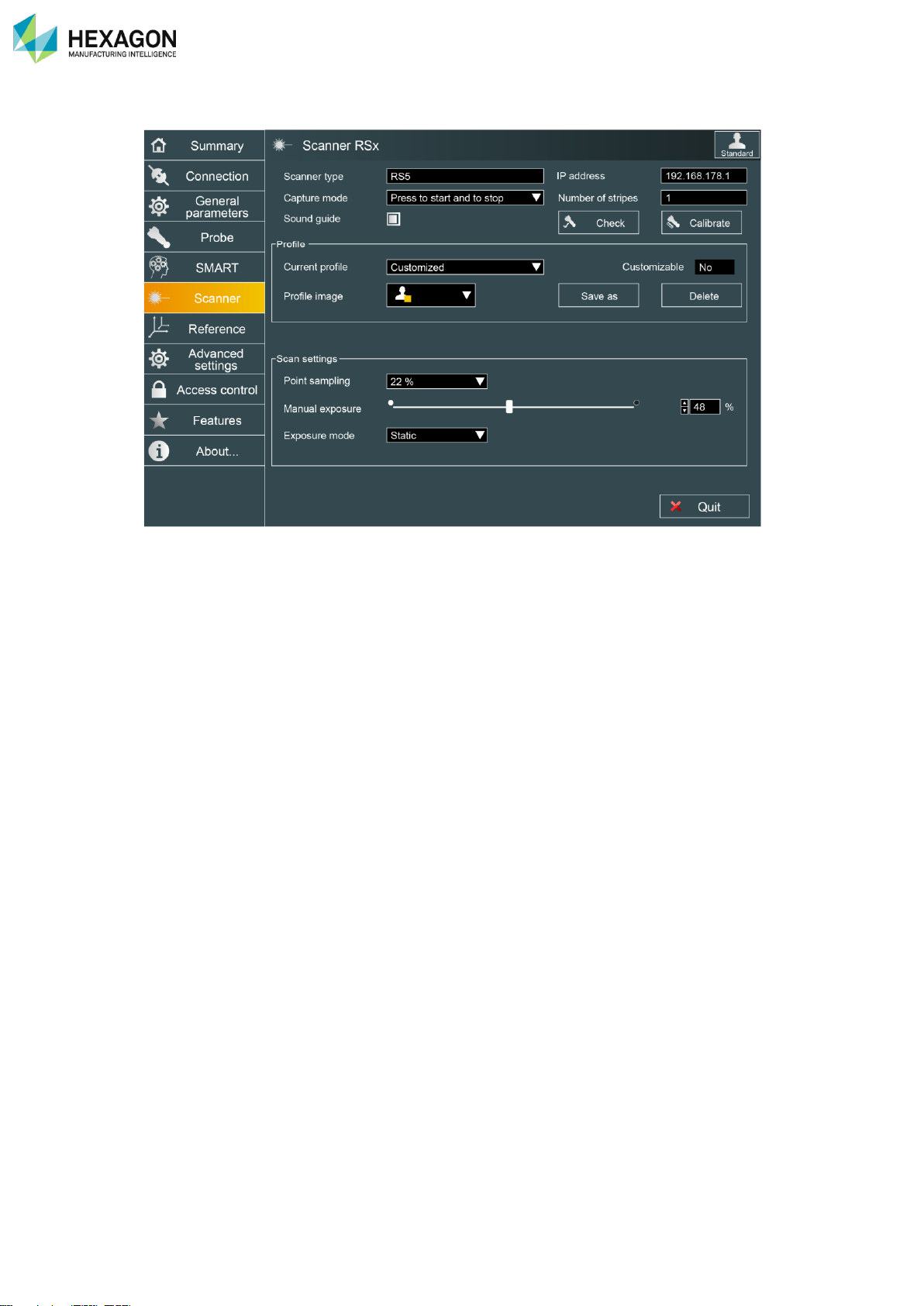
RDS Control Panel
H000002007-RDS User Manual │Version 5.0.0 (2018-09-17) │64
D.7 SCANNER
Scanner tab appears only when a scanning head is detected on the arm.
The parameters depend on the type of scanner.
Page 66
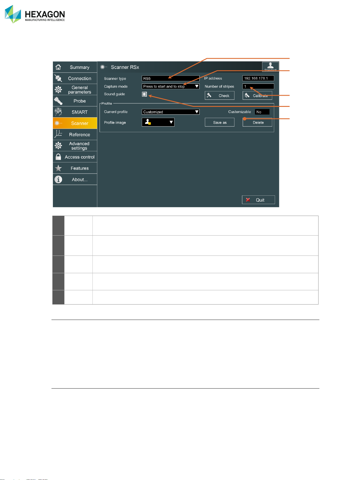
RDS Control Panel
H000002007-RDS User Manual │Version 5.0.0 (2018-09-17) │65
D.7.1 COMMON ITEMS
1
Scanner
type
Shows the type of scanner (RSx, HP-L-20.8, HP-L-8.9, CMS108, LAS, LAS-XL)
2
Capture
mode
Defines the way to use the button (Keep button pressed / Press to start and stop / n not
empty stripes)
3
Nb
Stripes
Number of scan lines above which the scan stops.
4
Sound
guide
Emits a sound that helps to keep good height
5
Profile
This is used to save all the scanner settings into scanning profiles (see next chapter)
Capture mode
The capture mode defines the way to start and stop digitizing:
• “Press Button once to start and stop”: the button of the arm is used as a switch: one simple press-and-
release to start digitizing, another one to stop.
• “Capture while button is pressed”: press and hold the button to start and continue digitizing, release the
button to stop.
• “Capture n not empty stripes” (Service user profile only): press the button to start digitizing, then RDS
automatically stops when the defined number of stripes (“Number of Stripes” parameter) is reached.
Depth sound
While digitizing, a sound can be emitted from the arm, giving information about the distance between the
scanner and the surface to scan: when this option is activated, the closest the scanner is to the surface,
the higher the sound frequency is, and no sound is emitted if the scanner is out of the scanning window.
1
2 3 5
4
Page 67
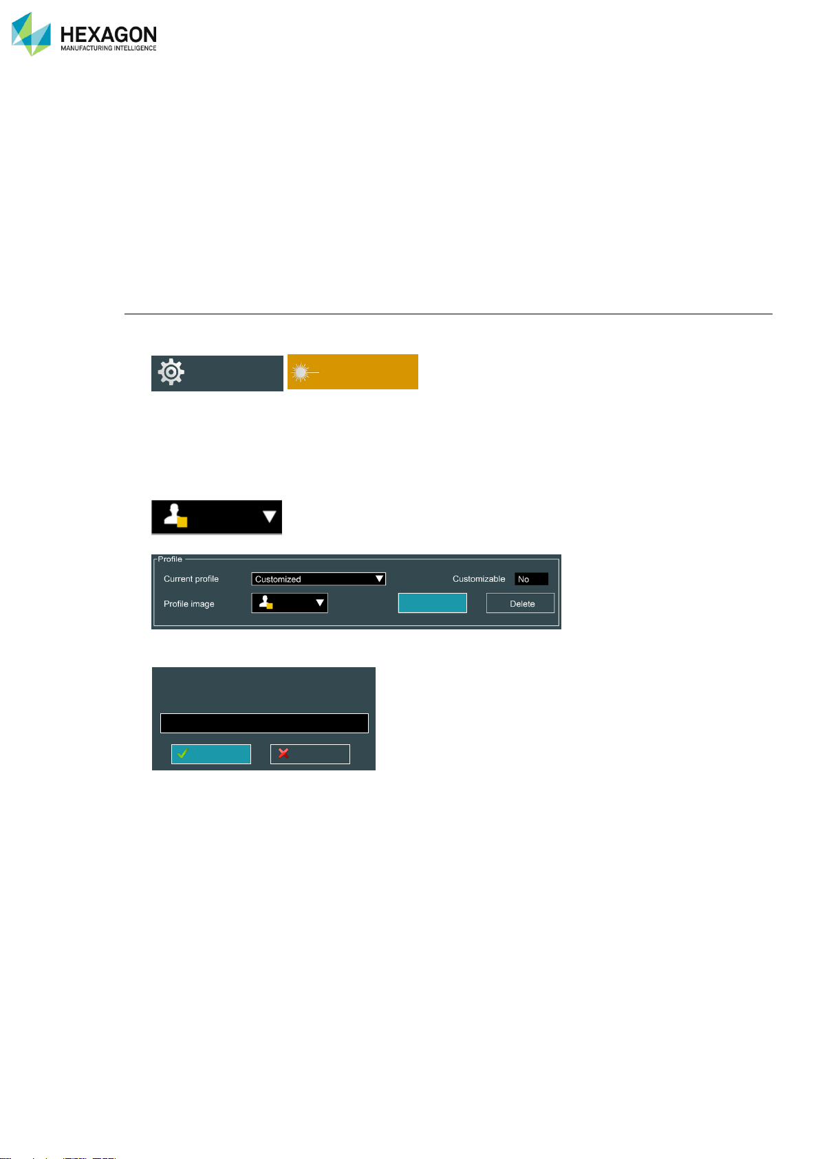
RDS Control Panel
H000002007-RDS User Manual │Version 5.0.0 (2018-09-17) │66
D.7.2 SCANNING PROFILES
To facilitate the configuration of the scanning parameters when typical settings are used, RDS can record
a set of parameters into a scanning profile.
RDS can memorize scanning profiles for each type of Laser scanner. It means that the set of parameters
(scanning mode, filters…) can be saved into different configurations.
Default profiles are already proposed by RDS, but the operator can save new customized profiles, in order
to quickly recall a configuration for a specific surface for instance.
Most of the scanning parameters are memorized. To enable easily one profile, the selection can be done
either in RDS Control Panel, either on the RDS scanning window, either even with the button on the
machine.
Save a profile (Advanced user)
Whatever the type of scanner, to save a new scanning profile:
1. Access RDS Control Panel, Tab Scanner
2. Select the profile to modify
3. Set the parameters according to your needs (current profile becomes “Customized”).
4. Choose an icon to associate with the profile
5. Click on “Save”
6. Give a name for the profile (existing profile can be selected from the drop-down list to be overwritten)
7. Click on “OK”
Control Panel
Scanner
Save as
Create a new profile or overwrite an existing
one.
Cancel
OK
▼
Page 68
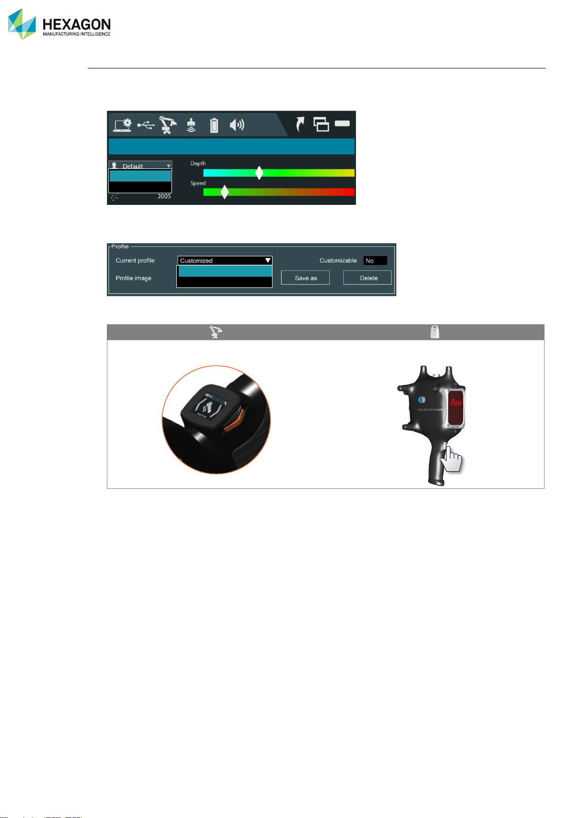
RDS Control Panel
H000002007-RDS User Manual │Version 5.0.0 (2018-09-17) │67
Use a profile (all users)
There are different ways to select and use a profile:
• From the RDS Agent: directly select the profile from the drop-down list on the RDS Scanning window.
• From RDS Control Panel: access the tab “Scanner” and select the profile in the drop-down list (don’t
forget to save Control Panel).
• With the machine: the main button of the tracker can be used to switch to the next profile:
Use the Q.A.M. (or Wrist Display on RA8-7) to
select the profile.
Double click on the scanner button to switch to
the next profile.
x2
Surface
Default
Surface
Default
Page 69

RDS Control Panel
H000002007-RDS User Manual │Version 5.0.0 (2018-09-17) │68
Default scanning profiles
RS2-5
HP-L-8.9
CMS108
HP-L-20.8
LAS
LAS-XL
Alignment
Sphere
Plane
✓
✓
✓
✓
✓
✓
✓
✓
✓
✓
This profile is designed for the scanner Alignment and is
automatically used during this process. At the end of the
Alignment, the profile returns to the originally selected one.
Standard
✓
✓
Default profile for RS5 (Linear) RS2,3,4 (static exposure) and HPL-8.9 (manual exposure)
Edge
✓ ✓ ✓
Profile for small details: highest resolution, but narrowest line.
Feature
✓ ✓ ✓
✓
Standard profile, mid-size part and some details.
Surface
✓ ✓ ✓
✓
Profile for large parts with a few details.
Line width (mm)
Points spacing (mm)
Sampling
Gain
Quality
filter
CMS
108
HP-L-
20.8
LAS
LASXL
CMS
108
HP-L-
20.8
LAS
LASXL
Points
Line
Edge
25
51
51
-
0.050
0.050
0.013
-
100 %
100%
Normal
On
Feature
60
63
63
228
0.060
0.025
0.013
0.226
100 %
100%
Normal
On
Surface
120
220
220
468
0.120
0.055
0.050
0.905
100 %
100%
Normal
On
Page 70
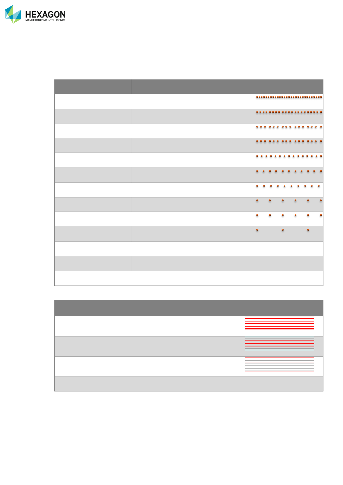
RDS Control Panel
H000002007-RDS User Manual │Version 5.0.0 (2018-09-17) │69
D.7.3 SAMPLING FILTER (HP-L-20.8 / CMS108 / RS3-5 / LAS / LAS-XL)
To improve the performance and speed of digitizing (depending on the performance of the computer and
the final software), it is possible to reduce the number of digitized points by skipping a regular percentage
of points, points by points or line by line.
Points sampling
HP-L-
20.8
LAS,
LAS-XL
CMS
108
RS3
RS4
None =keep all the points
(100 %)
✓ ✓ ✓ ✓ ✓
80 % = keep 4 points on 5
✓
✓
✓
75 % = keep 3 points on 4
✓
60 % = keep 3 points on 5
✓
✓
✓
50 % = keep 1 point on 2
✓
✓
40 % = keep 2 points on 5
✓
✓
✓
33 % = keep 1 point on 3
✓
25 % = keep 1 point on 3
✓
20 % = keep 1 point on 5
✓ ✓ ✓
✓
10 % = keep 1 point on 10
✓
✓
5 % = keep 1 point on 20
✓
✓
…
2.5 %= keep 1 Point on 40
✓
✓
Etc.
Line sampling
HP-L-20.8
CMS 108
None = keep all the lines
✓
✓
1/2 = keep 1 line on 2 (50% remain)
✓
✓
1/3 = keep 1 line on 3 (33% remain)
✓
✓
Etc…
Page 71
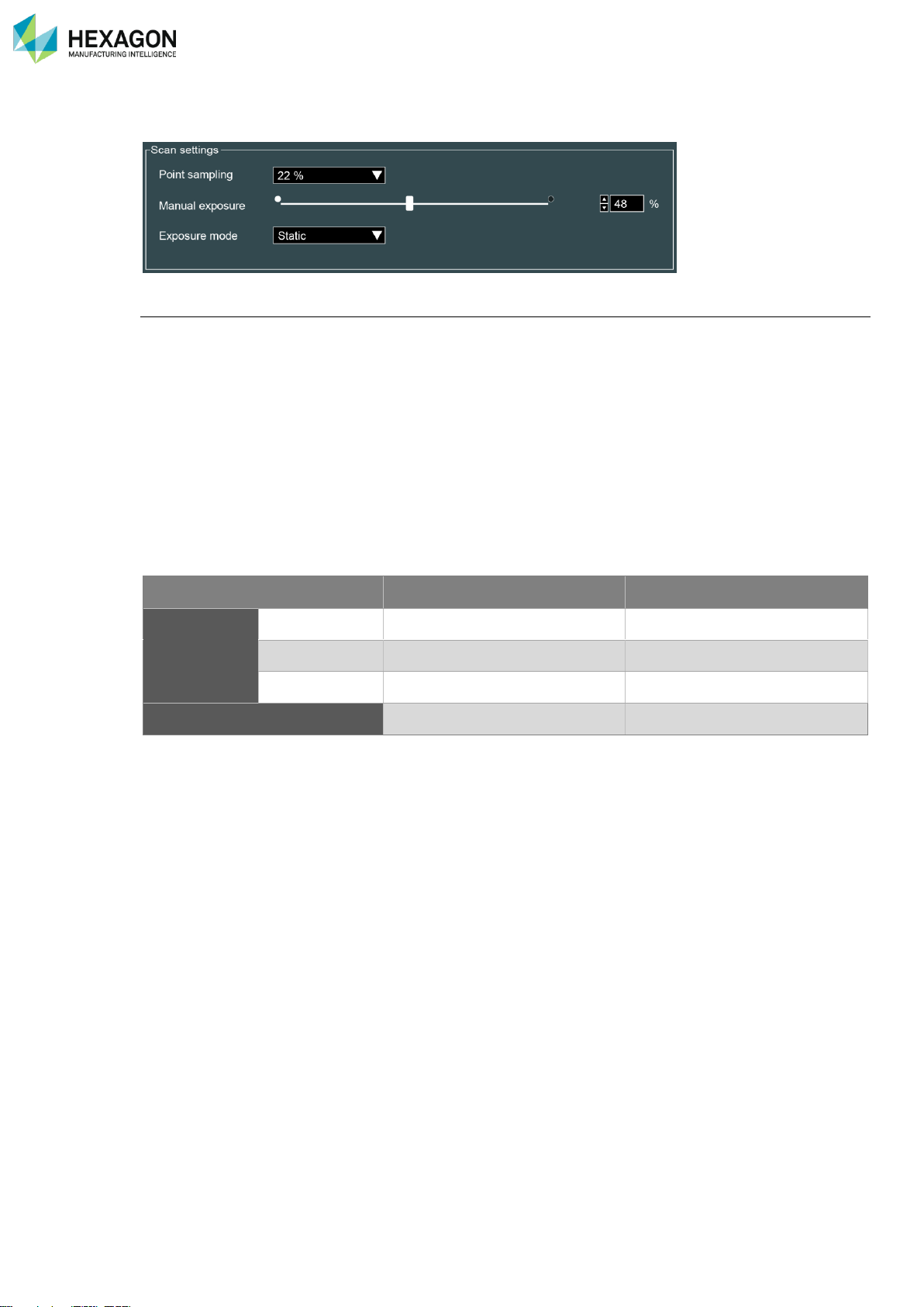
RDS Control Panel
H000002007-RDS User Manual │Version 5.0.0 (2018-09-17) │70
D.7.4 EXPOSURE (HP-L-8.9 / RS2-5)
Exposure modes
RDS provides 2 exposure modes:
• Manual mode: while scanning, the exposure is fixed. This is useful for a regular scanning, on a single
colour material. The adjustment of the exposure can be operated by 2 ways:
• Manual setup: the exposure is setup manually defining the exposure value. It is not possible to
setup while digitizing.
• Capture the exposure: RDS switches temporarily to an automatic exposure, until it is setup. It
is not possible to setup while digitizing.
• Auto mode (RS2-5 only): the exposure is setup automatically in real time even while digitizing: no
need to take care about set it up.
The mode can be also switched through the Quick Access Menu.
Static mode
Dynamic mode
Adjustment
Manual
✓
Capture
✓
Automatic
✓
Adjustment while scanning
✓
Page 72
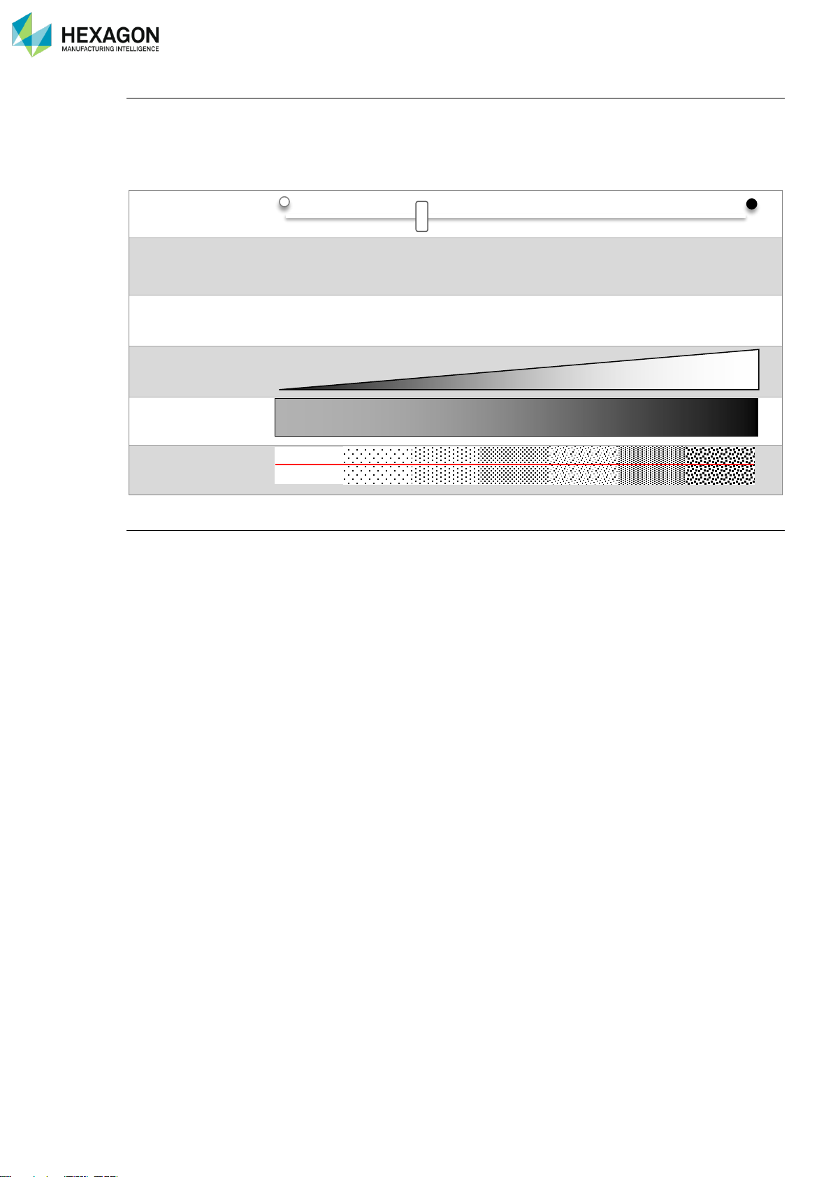
RDS Control Panel
H000002007-RDS User Manual │Version 5.0.0 (2018-09-17) │71
Manual setup (static mode)
Set up the exposure time of the camera: the higher the value is, the longer the camera is opened.
This parameter must be set up according to the ambient light and the darkness of the surface: set low value
for clear surface and higher value for dark surface. However, a high value increases the risk of noise points.
It is then necessary to adjust this parameter correctly.
Cursor
Percentage
1% 25% 50% 75% 100%
Exp. time
20µs 200µs 1000µs 4000µs 10000µs
Light capted by the
scanner
Darkness of the part
Noise
Capture the exposure (static mode)
RDS provides a process to setup automatically the exposure.
This exposure can be done with through the Quick Access Menu (Q.A.M.).
Access the Q.A.M. with a press on the 3-States button and select “Capture the exposure”.
Place the scanner over the surface: the scanner switches to a setup mode. Wait until the adjustment is
finished (the exposure value is stabilized, giving correct number of points): the arm emits 2 beeps.
Page 73
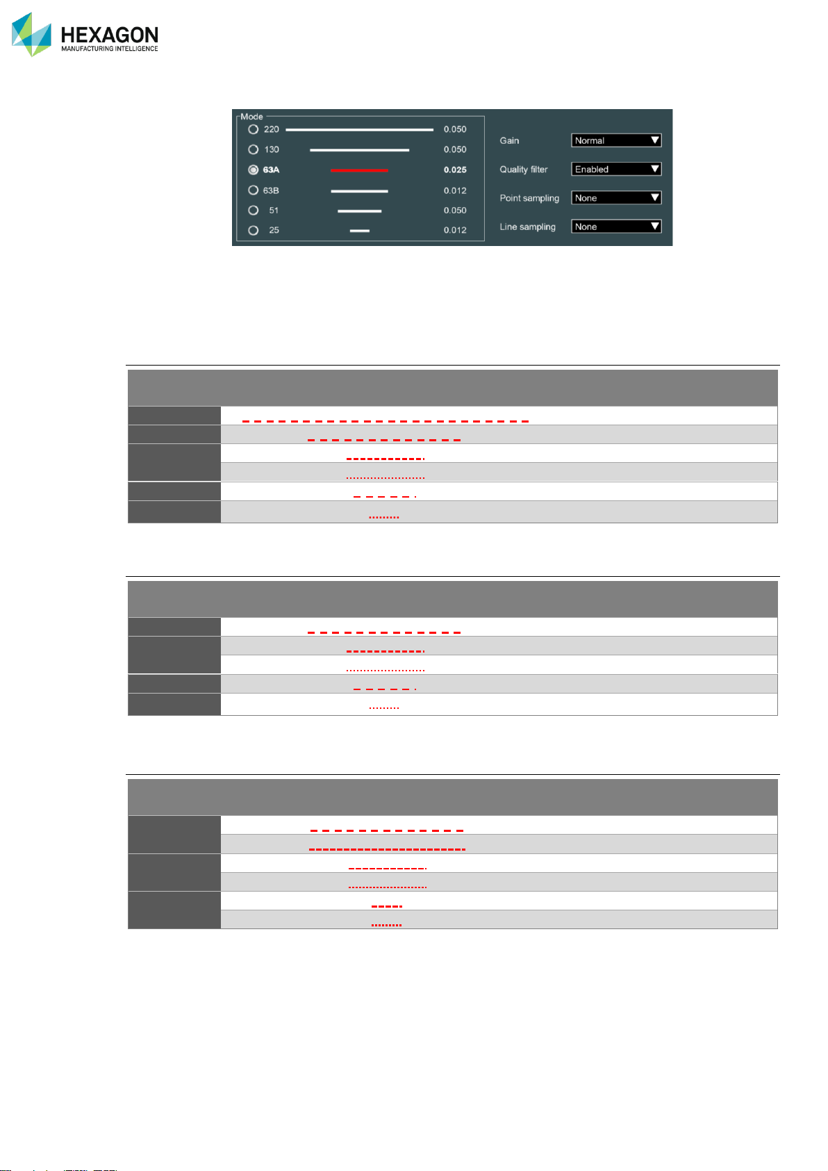
RDS Control Panel
H000002007-RDS User Manual │Version 5.0.0 (2018-09-17) │72
D.7.5 SCANNING MODES (HP-L-20.8 / CMS108 / LAS, LAS-XL)
CMS108, HP-L-20.8, LAS and LAS-XL scanners can digitize using different widths and resolutions.
Line length: defines the width of the laser (width in mm).
Point Spacing: defines the resolution distance between digitized points (points spacing in mm)
HP-L-20.8 / LAS scanning modes
Line width
(mm)
Laser line
Point spacing
Rate
(Hz)
220 0.050
37
130 0.050
51
63
0.025
50 0.013
28
51 0.050
100
25 0.013
50
Table 1 : HP-L-20.8 / LAS scanning modes
LAS-XL scanning modes
Line width
(mm)
Laser line
Point spacing
Rate
(Hz)
468 0.905
51
228
0.452
50
0.226
29
182 0.905
100
91
0.226
50
Table 2 : LAS-XL scanning modes
CMS108 scanning modes
Line width
(mm)
Laser line
Point spacing
Rate
(Hz)
120
0.120
30
0.060
15
60
0.060
51
0.030
29
25
0.050
53
0.025
36
Table 3 : CMS108 scanning modes
Page 74

RDS Control Panel
H000002007-RDS User Manual │Version 5.0.0 (2018-09-17) │73
D.7.6 GAIN – QUALITY FILTER (HP-L-20.8 / CMS108 / LAS / LAS-XL)
Gain (Normal/High/Very High)
The gain permits to improve the ability of the scanner to get points in difficult conditions. The sensor should
typically be used with gain set to Normal. When measuring dark, glossy or translucent surfaces, in the event
it is hard to capture data you can set the gain to High or Very High (except CMS108).
The metrological performance of the system can be affected when gain is set to High or Very
High since the likelihood of low quality data being generated is increased.
However, if the quality filter is enabled, these data should be automatically removed
Quality filter
The sensor has a quality filter to remove points which are deemed to be low quality, including:
• Double reflections
• Poor quality data on edges
• Isolated points/outliers
When measuring dark, glossy or translucent surfaces, in the event it is still difficult to capture data with gain
set to High, you can also disable the quality filter at the cost of overall reduced data quality.
The metrological performance of the system is not guaranteed when this filter is disabled
since low quality data may be generated
Page 75
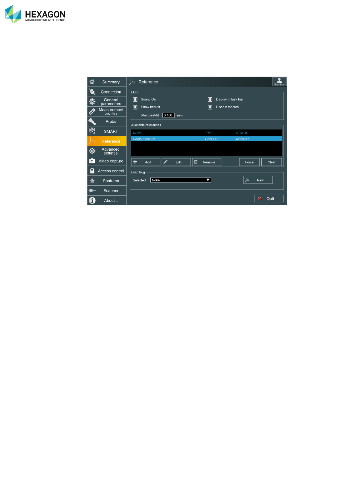
RDS Control Panel
H000002007-RDS User Manual │Version 5.0.0 (2018-09-17) │74
D.8 AUXILIARY REFERENCING (ARMS)
RDS control panel offers the possibility to position the system on several places, linking the different
positions by a reference, extending then the measurement volume.
Several solutions are available:
• Simple arm Leap-Frog: consists by taking same points before and after moving the arm.
• Grid Lok: permits to position the arm anywhere on the Lok floor, and reference the position by taking
Lok points.
• Space Lok: permits to move the arm around the “Space Lok” tool
• Part / Tool Loks: used to move around the part / tool.
• Load a reference from a file
Page 76
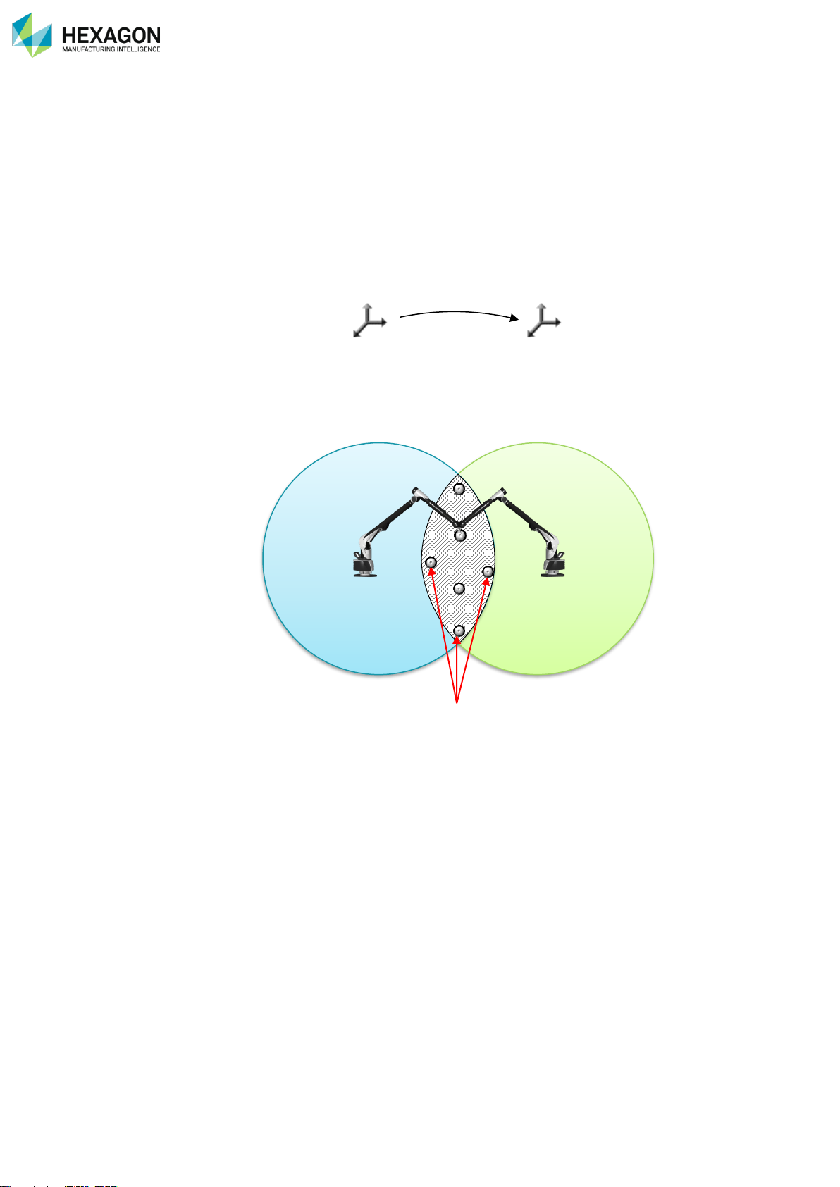
RDS Control Panel
H000002007-RDS User Manual │Version 5.0.0 (2018-09-17) │75
D.8.1 REMINDER: THEORY ABOUT MOVING A MEASUREMENT DEVICE
To move the arm from one place to another one, Leap-Frog is using a script in RDS Data Collector: click
on “New”, RDS Data Collector appears, executing automatically a Leap-Frog script.
During a measurement, both parts that are the measurement system and the part to measure must be
imperatively interdependent from each other, that means any displacement is forbidden.
When the part to be measured is larger than the measurement device can do, it becomes necessary to find
a way to move one (arm or part) to be able to measure the inaccessible zone.
That means moving « without moving », having a perfect knowledge of the movement done (distance,
orientations, offsets…)
Technically, such a displacement is a reference change (from a system of axes N°1 to a system of axes
N°2), the start (Ref N°1), is then Machine reference. (RM).
To allow the software to know this displacement in all details, we use elements that will be accessible from
both positions of the measuring device: those elements measured from both positions, the software
comparing them, will calculate a displacement « matrix »: displacement in X, Y and Z, of the origin point,
and each rotation it underwent between both positions (along X, Y and Z).
Overlap points
The displacement method consists by an « Overlap » method, using geometric elements, probed identically
from both positions.
Depending on the accuracy of the measurement device, this displacement will necessary generate a loss
of accuracy, as it results from two measurements of the elements.
To minimize this lost, it is important to optimize the method. Here are the main rules:
Use the most accurate measurement device
Look for the positions of the measurement device as to have a lap area (accessible from both positions) as
large as possible, as to « stabilize « as best as possible the displacement. (as the 4 feet of a table are on
each extremities of the table, not at the centre).
Use a maximum number of elements (geometric elements used for this Leap-Frog) (a table is more stable
on 4 feet than on 3).
Use good quality elements (a machined bore will be much better than a tapping not clean).
The type of elements used will define the calculation method used by the software.
« Leapfrog » name is often used.
NB: moving the measurement device or moving the part comes to the same thing
RM
Pos2
P 1
P 2
Page 77
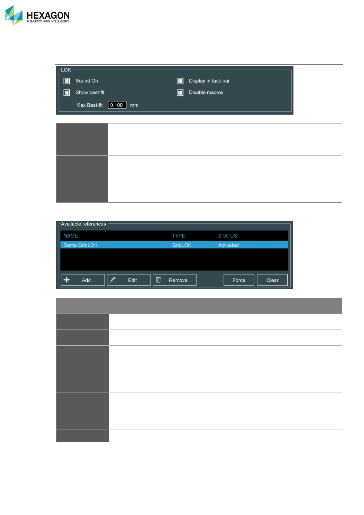
RDS Control Panel
H000002007-RDS User Manual │Version 5.0.0 (2018-09-17) │76
D.8.2 DESCRIPTION OF THE REFERENCE TAB
LOK / VPS
Sound On
Activate the sounds when VPS / Lok are used
Show Best Fit
Display the best fit maximum error when the positioning is done
Display in task
bar
Display an information status window in the task bar after the calculation
Disable Macro
Max Best-Fit
Maximum authorized best fit value, over which the reference is not accepted.
Available references
Item
Description
Values
Available
references
Display the list of all references.
Name
Name given to the reference
Type
Type of reference
Leapfrog
GridLOK
…
Memory
Permanent
Temporary
Status
Shows which reference is engaged
Active (available)
Engaged (used)
Dongle detected (LOK)
Force
Clear
Page 78
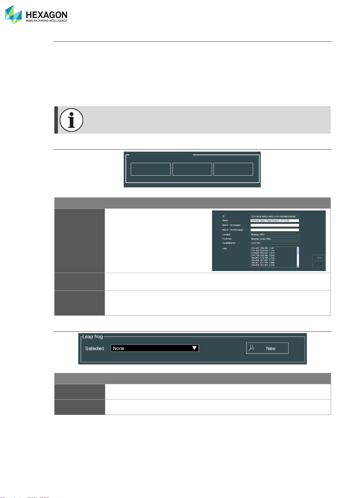
RDS Control Panel
H000002007-RDS User Manual │Version 5.0.0 (2018-09-17) │77
Type of Reference:
• Permanent: a reference can be memorized in the arm memory, to be able to use it even after a restart
of the system: this can be necessary if the work is not finished and has to be continued after a restart.
• Temporary: (default for Leap-Frog) the reference is not memorized in the arm memory, but simply
temporary on the computer, until the arm is restarted. Then the reference is lost. In case there could
be a necessity to stop the work and restart the system, then it is recommended to define this reference
as a permanent, to save it, and when the work is finished, to delete it
All references notified as “Permanent” are saved in the arm memory: if the arm is connected
on another computer, it is not necessary to reload those references.
Reference components
Item
Description
Edit
Display the characteristics of the
selected reference.
Add
Use to add a reference from a file, or
to add a configuration file for LOK
Remove
Use to delete a reference or LOK
configuration from the memory of the
arm.
Leapfrog choice
Item
Description
Values
Selected
Use to select which of the active references is in-use
New
Use to move the arm by a Leap-Frog method.
Reference components
Edit
Add
Remove
Page 79
RDS Control Panel
H000002007-RDS User Manual │Version 5.0.0 (2018-09-17) │78
D.8.3 LEAPFROG IN RDS
Principle
RDS transmits the coordinates of probed points to final software.
By operating the Leapfrog at the level of RDS, the displacement becomes transparent to the final software.
That means it’s like if it was a very large measurement volume. We can then use the final software as if
there was no displacement.
To do, we use a group of points as Leapfrog elements: it can be cones, holes or angles in which the ball
probe is seated, or targets, at the centre of which the point probe is placed (attention, however this way is
less accurate).
This group needs at least 3 points that will be probed IN THE SAME ORDER from position 1 and position
2.
Only one probe can be used for this operation.
Method
In RDS Control Panel, in RDS Data Collector or directly from the task bar, access to new Leapfrog.
1. Control Panel: Tab Reference, click on “new”
2. Place or choose correctly the points to probe
3. Run the script
4. Probe the points from 1st position, notice the order.
5. When all points are probed, move the arm, (make sure it is well fixed) and probe again the points IN
THE SAME ORDER
6. When prompted, enter a name for this displacement, and select if it is a temporary or permanent
reference.
7. Click on OK: it’s over.
A second displacement is possible by the same way, then third …however, a loss of accuracy may happen
each time.
Measuring
Instrument
Application
Software
RDS
Page 80
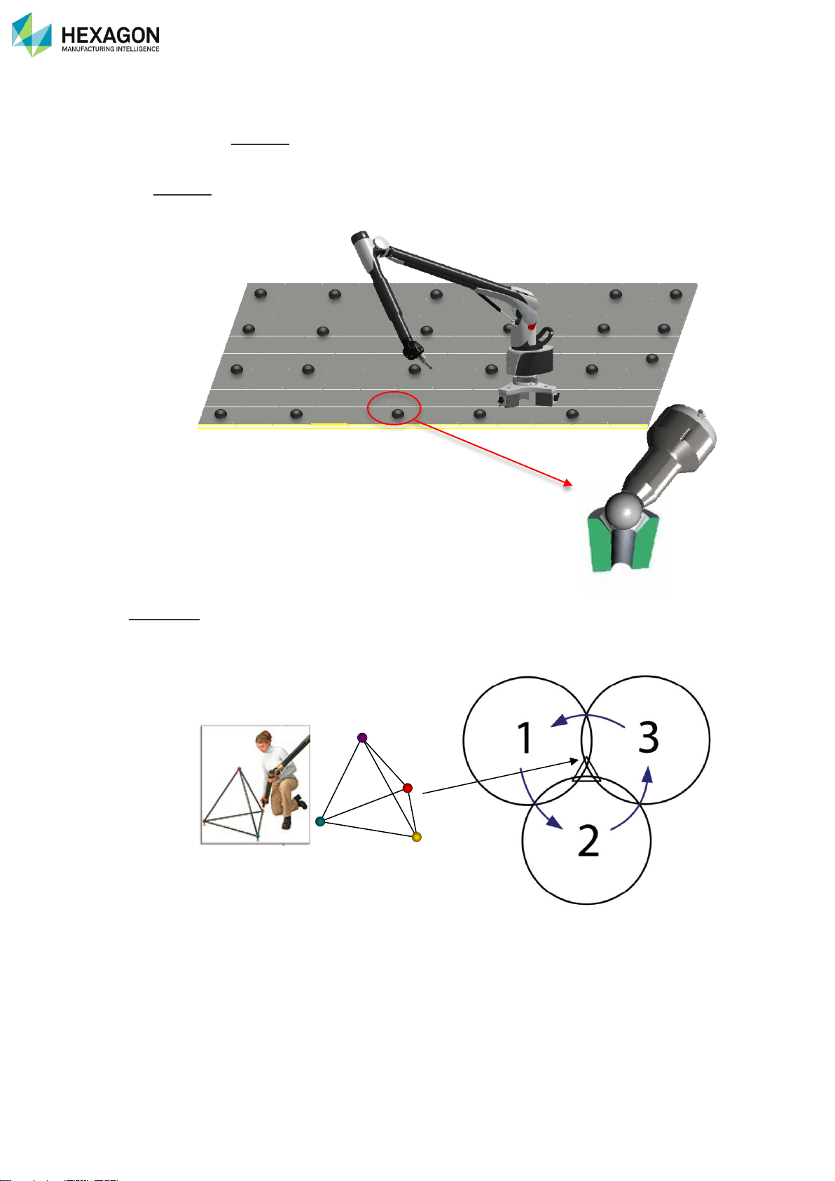
RDS Control Panel
H000002007-RDS User Manual │Version 5.0.0 (2018-09-17) │79
D.8.4 GRIDLOK / SPACELOK
The principle of GridLOK is comprised of a grid system with conical seats installed in a concrete slab or
steel plate and aligned with a laser tracker. This means it can cover a very large volume.
Then at any moment, by taking points on 3 seats, RDS calculates automatically the position of the arm on
the GridLOK. Measurements can be done, in any software, and the arm moved at any moment, only 3
points are necessary to take, without any button to press or click on, any other operation than hit 3 points
on the seats.
SpaceLOK recalls the principle of GridLOK, but instead of a large grid of several seats on a floor, the only
4 seats are fixed on a triangular 3D pyramid, that can be displaced (and disassemble in some cases). This
tool can then be place at the centre of the part to measure, as to move the arm all around the SpaceLOK
tool.
Page 81
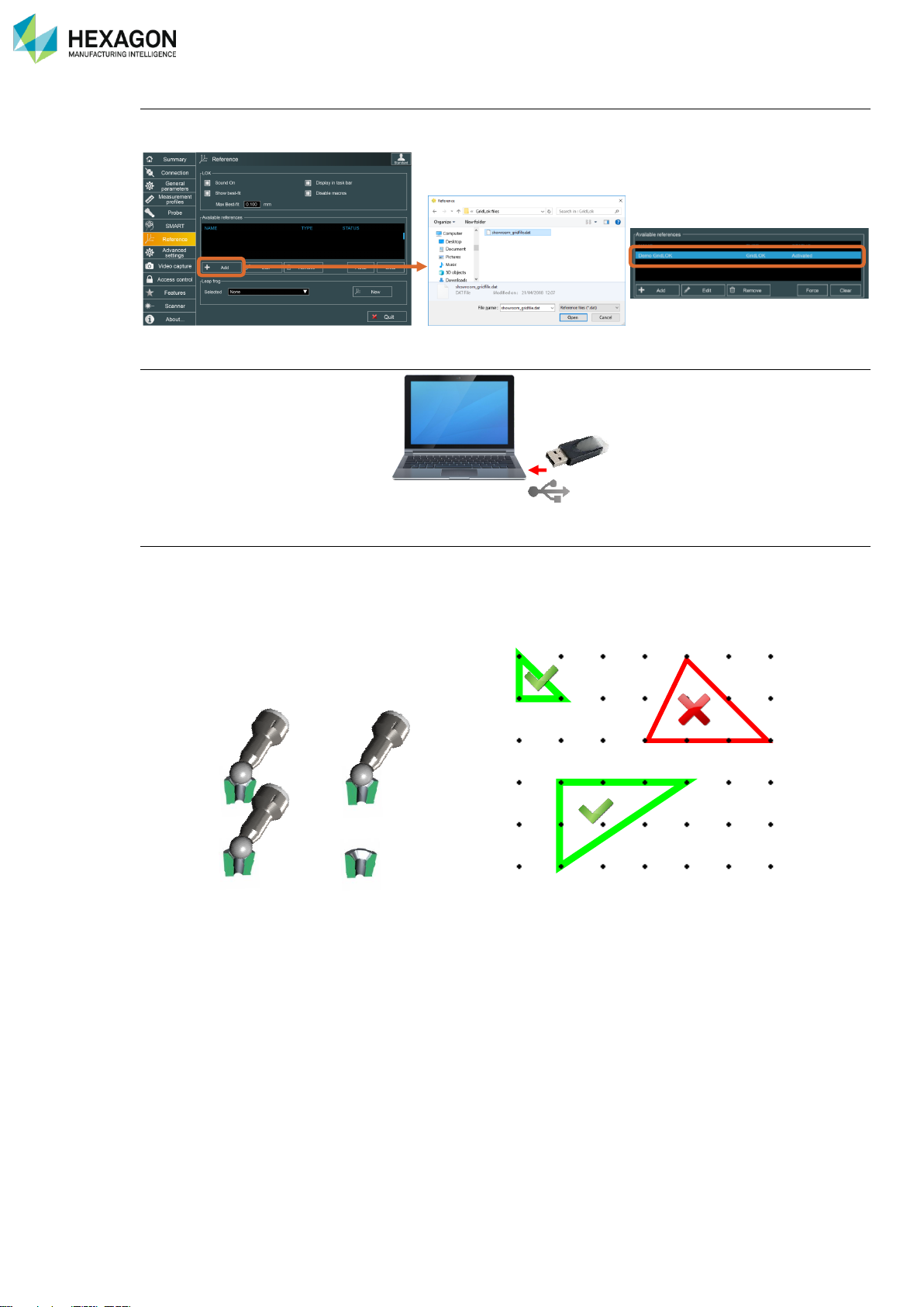
RDS Control Panel
H000002007-RDS User Manual │Version 5.0.0 (2018-09-17) │80
Load the configuration file on the arm
Open RDS control Panel, tab Reference, then Load the Alignment GridLOK file (*.dat): the GridLOK file is
then “Active” in the list of references. Save and Exit RDS
Plug-In the GridLOK dongle on the USB port of the computer.
GridLOK is then ready to use
At any moment, under any software or even out of any software mount the ball probe dedicated to the
GridLOK on the arm, and probe 3 GridLOK points. Attention, the three points must form a 90° triangle
For each point, no need to hit the button, simply keep the probe seated in the target a few second, until a
beep is emitted, then move to next target.
1 2 3
Page 82
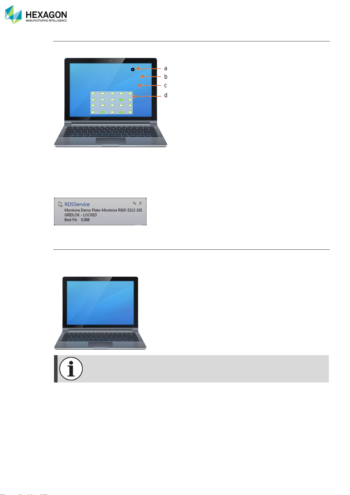
RDS Control Panel
H000002007-RDS User Manual │Version 5.0.0 (2018-09-17) │81
Automatic calculation
RDS calculates automatically the position of the arm on the workshop and display the best fit value on the
screen:
a. GridLOK Alignment file name
b. GridLOK status (Locked / Unlocked)
c. Best-fit value
d. Representation of the GridLOK targets, highlighting the measured ones
In RDS Control Panel, Reference tab, the GridLok reference appears as “Engaged”
The RDS status notification reminds then:
Back to machine reference
To come back to original Arm reference, take three times the point. Be sure to slightly pause between each
point, then RDS will display status information on the screen
Each time the arm is disconnected from RDS, the GridLOK is unlocked. Remeasure seats to
recalculate the GridLOK position.
a
b
c
d
GridLok Demo
GridLOK Locked
Best-Fit: 0.014
GridLok Demo
GridLOK Unlocked
Page 83
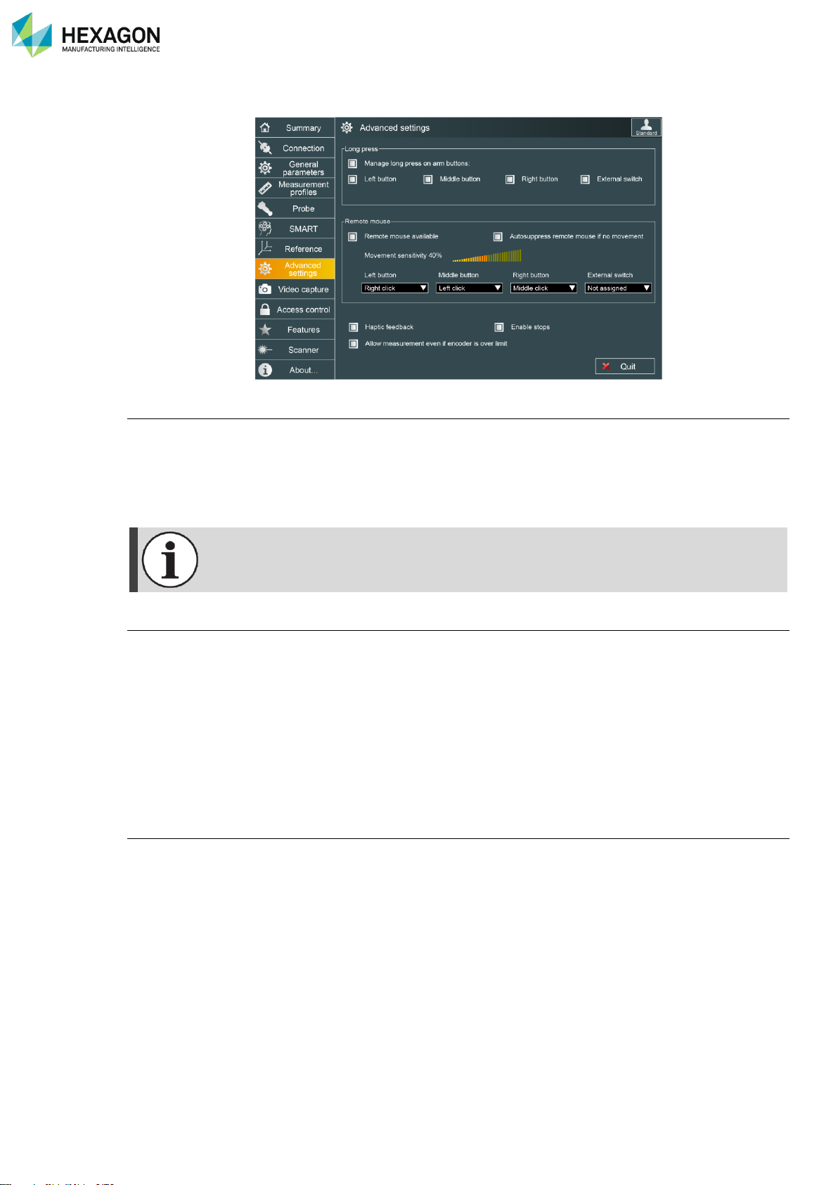
RDS Control Panel
H000002007-RDS User Manual │Version 5.0.0 (2018-09-17) │82
D.9 ADVANCED SETTINGS (ARMS)
Manage long press on arm buttons
Some measuring software are using separately short click and long press on the button of the device. The
limit between short and long press is approximately 1second. Then the function on the software will be
different (validate / cancel, …).
By default, RDS manages this feature, but some software (such as GPad) already manages it. In this case,
it is recommended to deactivate it in RDS.
The long press is not active when the mouse is active.
Remote mouse
Through the last axes of the measuring device, the mouse in Windows® can be controlled by the arm.
• Each button (button 0, 1, 2, 3) can be affected to a specific mouse function (Left Button, Middle
Button, and Right Button).
• Movement sensibility (in % of highest sensibility): defines the minimum movement speed of the arm to
start moving the pointer. This is useful to manage double click.
• Remote mouse available: unselect to completely deactivate the mouse of the arm.
• Auto suppress remote mouse if no movement: if RDS detects no movement of the arm, remote mouse
is automatically deactivated, and reactivated as soon as the arm moves again.
Haptic feedback
Latest arms (V3 or upper) are equipped with a haptic motor in the wrist. This produces a haptic feedback
when one axis is reaching the electronic limit. This feedback can be deactivated with this option.
Page 84

RDS Control Panel
H000002007-RDS User Manual │Version 5.0.0 (2018-09-17) │83
Enable stops (only for Alignment Centres)
Enable / disable alarm and security on mechanical stops of the axes (B, D and F axes).
When enabled, when one axis (B, D or F) reaches the limit, measurement and mouse will be stopped.
NOTICE
For security and constraints reasons, it is recommended to always keep this setting “on”.
Allow measurement even if encoder over limit (only for Alignment Centres):
Enable / disable the possibility to take points when the arm reaches its limits (i.e. if it is under constraints).
Page 85
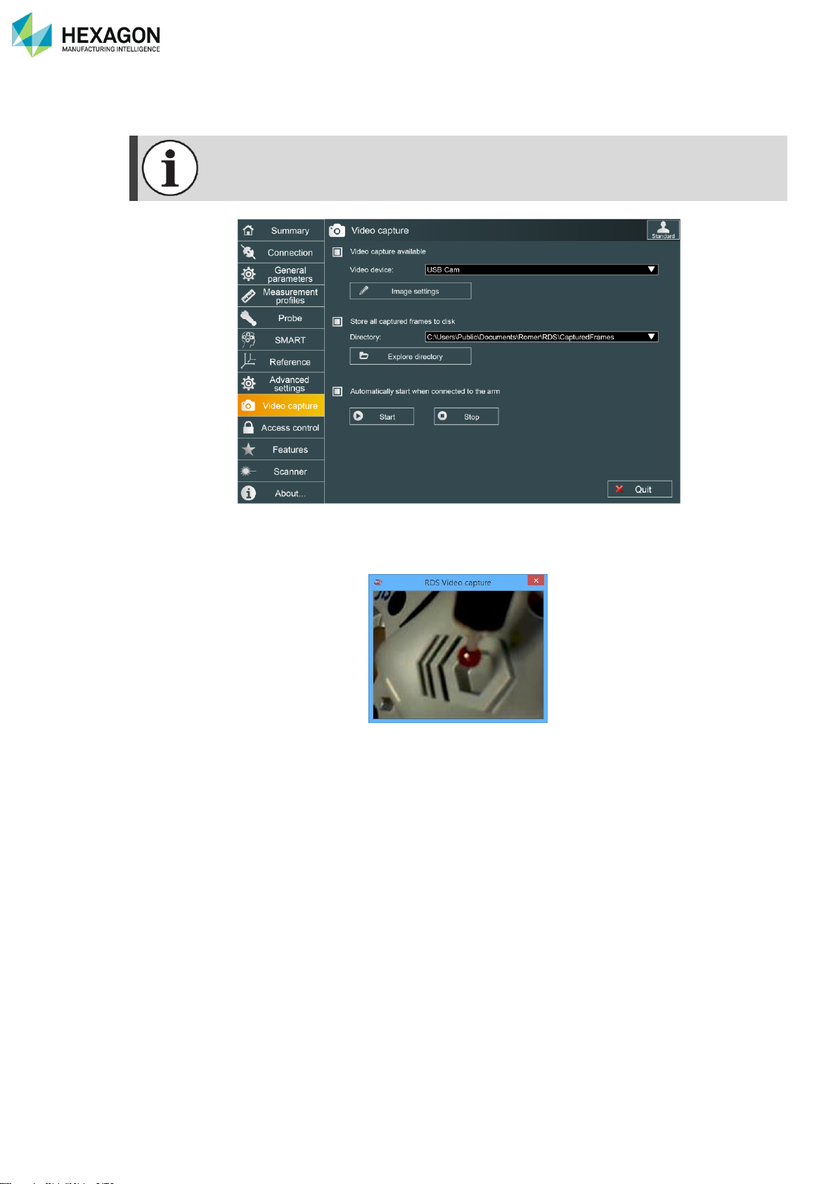
RDS Control Panel
H000002007-RDS User Manual │Version 5.0.0 (2018-09-17) │84
D.10 VIDEO CAPTURE (FOR EQUIPPED ARMS)
This tab is displayed only for a 6-axes 75 (V1-V2-V3) and 73/77 V3 series ROMER Absolute
arm equipped with a camera on the wrist.
RDS can manage video pictures coming from USB video camera. The camera can be either the one located
on the wrist of the absolute arm, either an external USB webcam. Some measurement software are able
to manage, Align the video camera and use the picture.
When Video capture is activated, a picture is automatically taken and sent to the measurement software
each time a point is taken with a contact probe.
The picture can be also saved on the hard drive when this item is select in this RDS Tab.
This tab is then used to setup this management.
Page 86
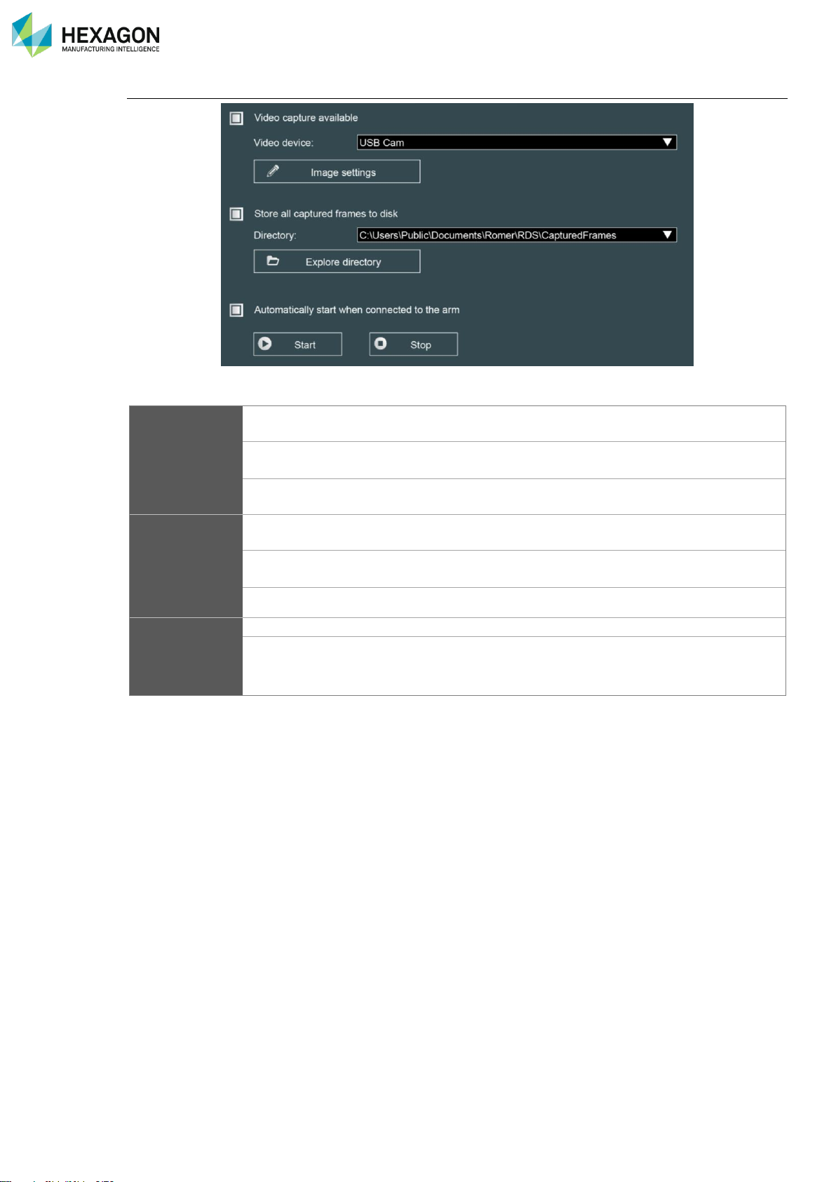
RDS Control Panel
H000002007-RDS User Manual │Version 5.0.0 (2018-09-17) │85
Main settings
Video capture
available
Activate the use of camera by RDS
Video device
Use to select the camera to use
Image Settings
Gives access to change the parameters of the image (see next
paragraph)
Store captured
frames to disk
When this option is ticked, the taken picture is also saved on the computer, on the
specified folder
Captured frames
Path for stored frames and pictures (please contact your local
agent for modification)
Explore directory
Opens Windows® explorer on the specified folder.
Start / Stop
Start / Stop
Manually starts / stops the video
Automatically start
video …
As soon as the arm is connected, video capture starts, and the
video window is displayed
Page 87
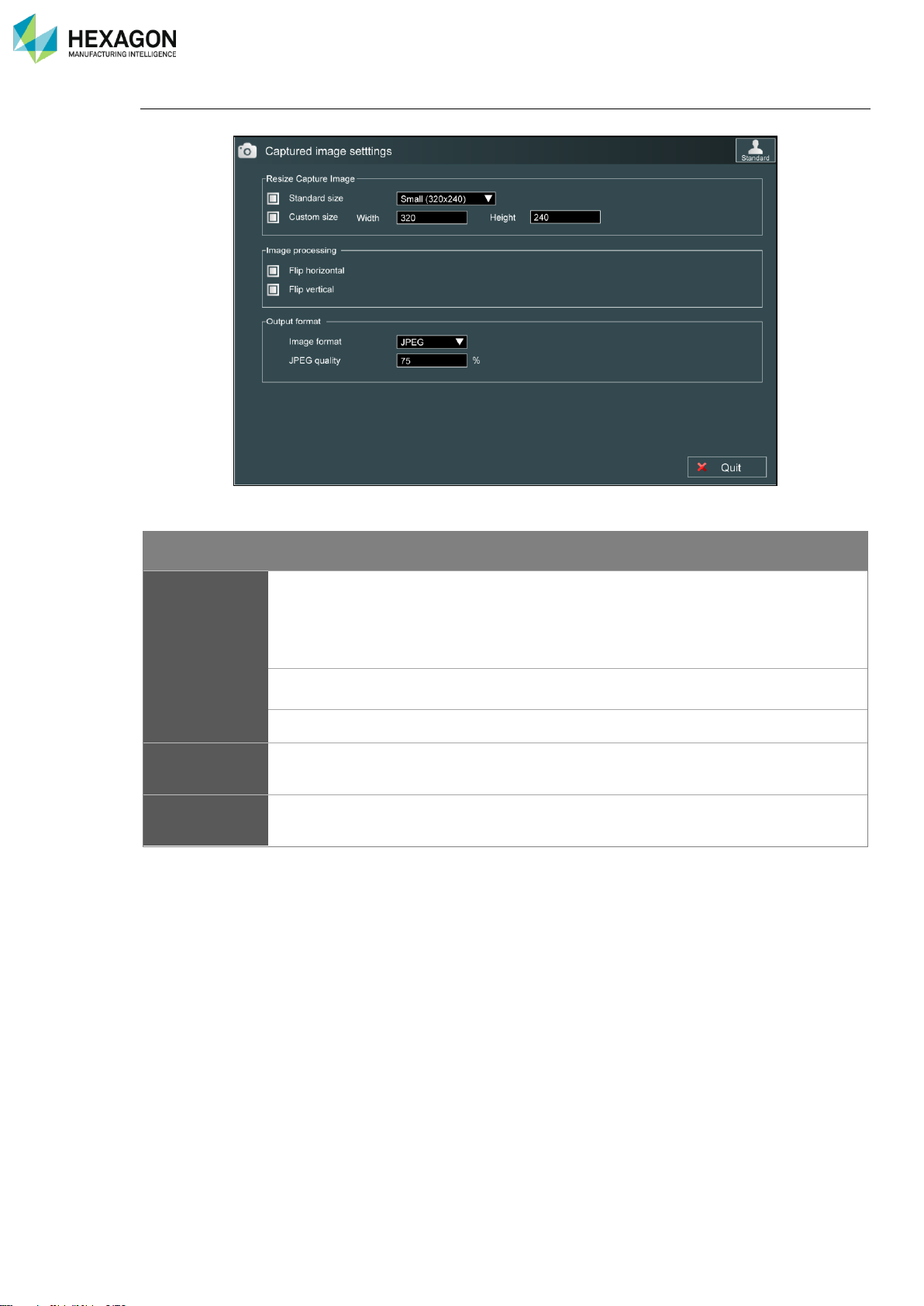
RDS Control Panel
H000002007-RDS User Manual │Version 5.0.0 (2018-09-17) │86
Image settings
By clicking on “Image settings”, the user accesses to the parameters of the captured picture:
Resize captured image: definition of the resolution of the image (in pixels).
Item
Description
Values
Resize
captured image
Standard size
Predefined sizes
Tiny (160x120)
Small (320x240)
Medium (480x360)
Large (640x480)
Custom size
Used for other resolutions
Width / height
Custom resolutions
In pixels
Image
processing
Flip Horizontal
Flip vertical
Used to mirror the image
Output format
Format and quality of the shot picture
Jpeg
Bmp
Page 88
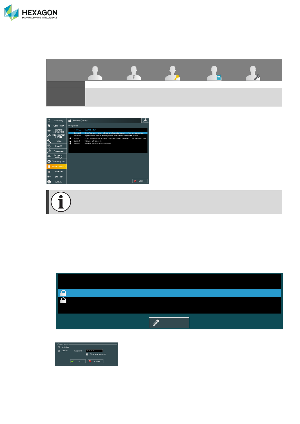
RDS Control Panel
H000002007-RDS User Manual │Version 5.0.0 (2018-09-17) │87
D.11 ACCESS CONTROL (ADVANCED USER)
User profiles define the levels of authorization in RDS.
Except the Standard profile, the access to the user profiles is protected by a password and/or a Feature
code.
Standard
Advanced
Admin
Support
Service
Level
1 2 3 4 5
Protection
None
Password
(default =
“Advanced”)
Password
(default =
“Administrator”)
Feature Key
Feature Key
The Access Control tab is used to manage those passwords.
Only profiles equal or higher than the one to modify can do it (for example: Advanced user
cannot modify the Administrator profile).
To be sure about the password that has been entered, click on “Show plain password”: the asterisks are
replaced by the real characters.
D.11.1 HOW TO … MODIFY THE PROTECTION OF A FUNCTION
1. Open RDS Control Panel, tab « Access Control » (use at least the Advanced profile).
2. Select the profile to change and {Modify}
PROFILE
DESCRIPTION
Standard
Shop floor user, he can only perform checks but cannot perform compensations.
Advanced
Higher level customer, can perform both compensations and checks.
Admin
Customer administrator who is able to change passwords for the advanced user.
Support
Hexagon Manufacturing Intelligence CO supporter
3. Tick « Unlocked »to remove the protection or “Locked” to activate or modify the password
4. Enter or change the password if necessary (“Locked”) and click on OK
Modify
Page 89
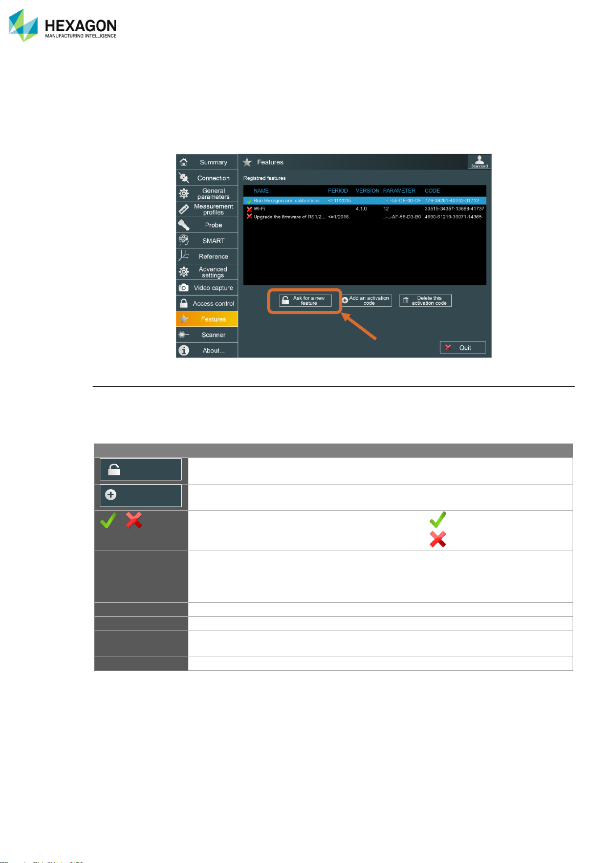
RDS Control Panel
H000002007-RDS User Manual │Version 5.0.0 (2018-09-17) │88
D.12 FEATURES (ARMS)
D.12.1 INTERFACE
Some features of RDS are protected and request an activation code.
This tab is used to manage such options (Wi-Fi connection / CO Alignment…):
Feature options
Features can be linked either to the S/N of the arm, either to the Mac address of the computer.
Temporary features and version-limited features are possible.
Each feature parameter is displayed (period, Mac address, S/N, …)
Information
Description
Displayed value
Button to get a request code for an option
(Advanced User profile)
Button to enter a new activation code
(Advanced User profile)
/
Shows if the option is valid or not
(valid)
(no more valid)
Name
Type of option
Run all Alignment
Diagnosis tools
Upgrade firmware
…
Period
Limitation date of the option (if limited)
Version
Limitation version of the option (if limited)
Parameter
Associated hardware identification
MAC address
Serial number of arm
Code
Activation code of the feature
Ask for a new
feature
Add an activation
code
Page 90
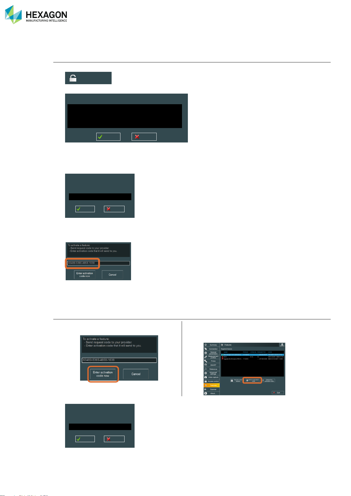
RDS Control Panel
H000002007-RDS User Manual │Version 5.0.0 (2018-09-17) │89
D.12.2 HOW TO ADD A NEW FEATURE (ADVANCED USER)
Ask for a new activation code:
1. Click on “Ask for a new feature”:
2. Then a choice of options is proposed:
3. Select the type of feature to add, and then click on “OK”.
4. Following window appears: by default, the serial number of the current connected measuring system
is displayed.
5. Enter Serial number of arm and press OK
6. A request code is given
7. Send the request code to your Hexagon Manufacturing Intelligence contact: give request code (20-digit
code), you’ll then get back activation code.
Enter the activation code
8. Once you have the activation code, click on
“Enter Activation code now”
Or from the main tab, click on “add an
activation code
9. Enter the code and click on “OK”
Ask for a new
feature
Please select the feature you want to activate:
Wi-Fi
Run single arm calibrations
Upgrade the firmware of a specific RSx
Upgrade the firmware of RS1/2 to RS3 (specific RSx)
OK Cancel
To unlock this feature, you need to give arm
Id you want to connect to.
OK
Cancel
Please enter feature code that has been
given by your supplier.
OK
Cancel
Page 91
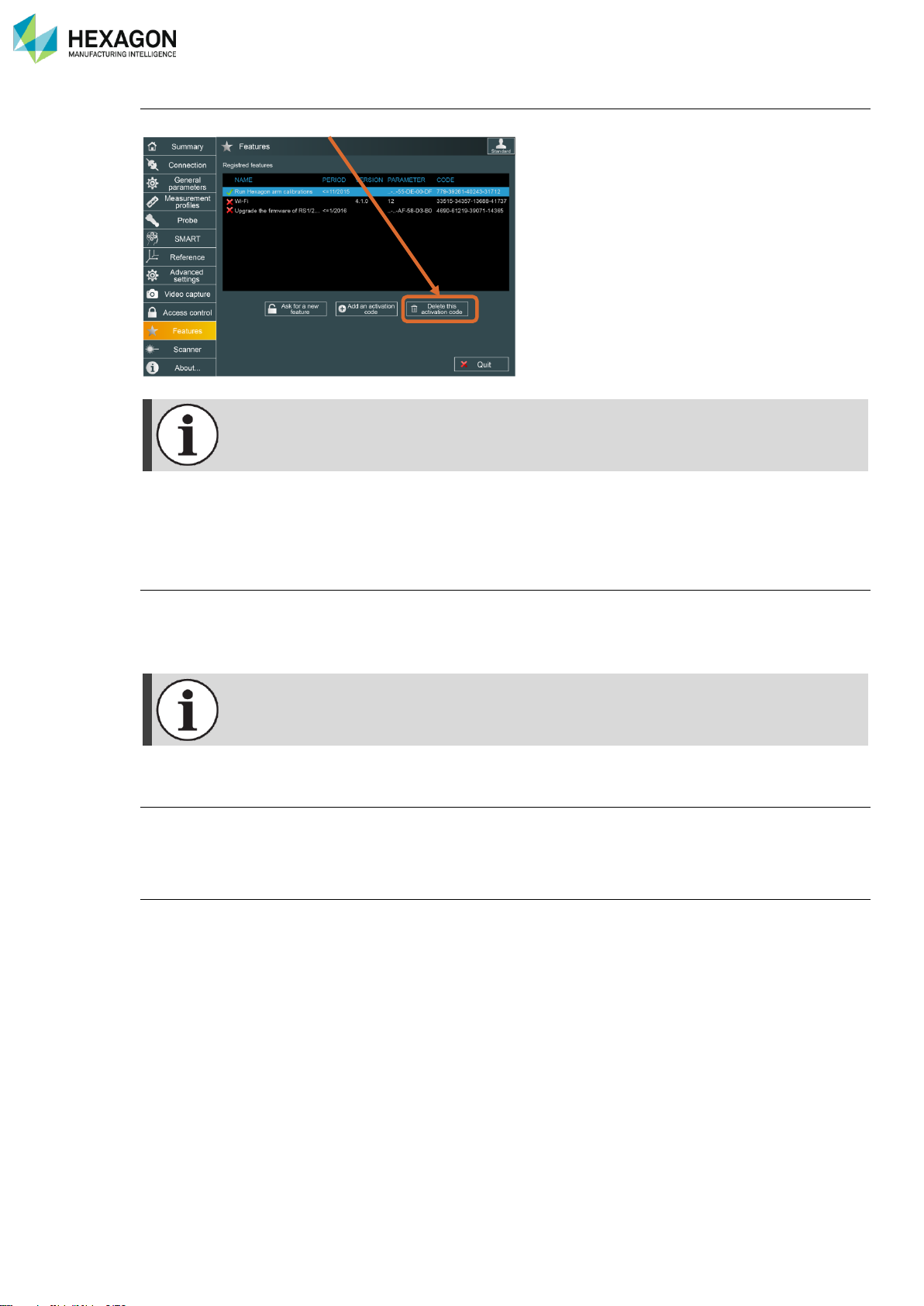
RDS Control Panel
H000002007-RDS User Manual │Version 5.0.0 (2018-09-17) │90
To remove a feature:
Select the feature, then click on “Delete”.
If RDS is reinstalled on same computer, it is not necessary to re-enter activation codes.
If RDS is reinstalled on a new computer, it is necessary to re-enter activation codes.
Make sure to keep those activation codes in a safe place
D.12.3 TYPES OF FEATURE
Wi-Fi (Multi Gage)
Default connection for NCA (ABSOLUTE and Multi Gage) is USB. Wi-Fi option has to be activated to be
able to use it on Multi gage.
Follow previous chapter to activate Wi-Fi.
Wi-Fi activation code is associated with the device and cannot be used with another device.
Alignment, Diagnostic tools
Hexagon Manufacturing Intelligence agents can use RDS to Align the system (under condition of training
and equipment). Request an activation code to Hexagon Manufacturing Intelligence.
RSx upgrade
To upgrade the ROMER scanner RS1 to RS2 or to RS3, a special feature code is necessary.
Page 92
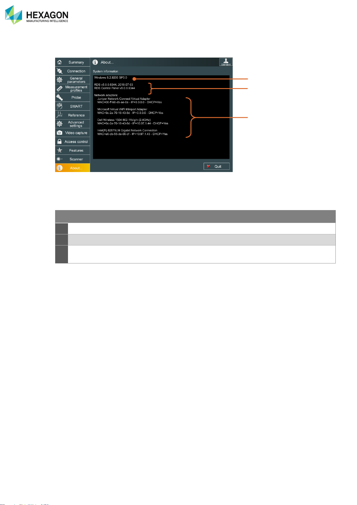
RDS Control Panel
H000002007-RDS User Manual │Version 5.0.0 (2018-09-17) │91
D.13 ABOUT
This tab displays useful information about the versions of RDS, Windows
®
, and about the computer’s
adapters.
SYSTEM INFORMATION
1
Windows …
Operating system version
2
RDS v…
Details of RDS version
3
Network adapters
Checking and details of all available network devices on the computer
(including Wi-Fi / Bluetooth / wired RJ45 network).
1
3
2
Page 93
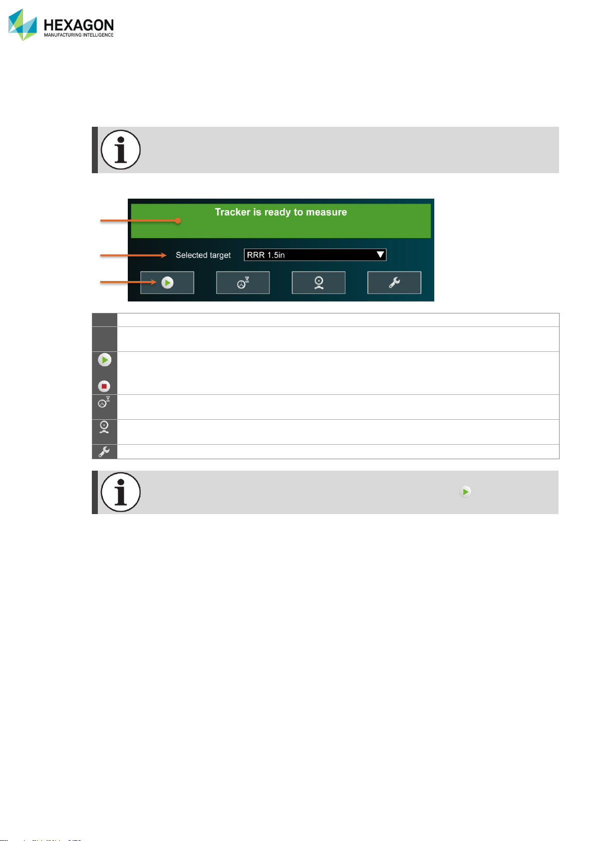
Tracker tools
H000002007-RDS User Manual │Version 5.0.0 (2018-09-17) │92
E. TRACKER TOOLS
Once a tracker is connected, RDS displays automatically configuration tools.
This window provides the options to control the reflector and measurement settings.
The Tracker window appears only when a software is connected to RDS, including RDS
Control Panel or RDS Data Collector.
1
Status
Tracker status
2
Selected target
Shows the active reflector, T-Probe or Scanner, and provides the list of
reflectors to manually select them.
/
Start
measurement
According to the settings,
• Triggers the measurement of a point
• Starts / Stops the measurement (continuous time or distance)
Stable probing
Activate / deactivate the auto-triggered point measurement: (after a
movement), once the reflector stabilized, the point is automatically taken.
Show OVC
Displays the video of the overview camera to guide the tracker to find the
target.
Settings
Opens the settings page.
The stable probing doesn’t prevent from manual points with the button .
1
2
3
Page 94
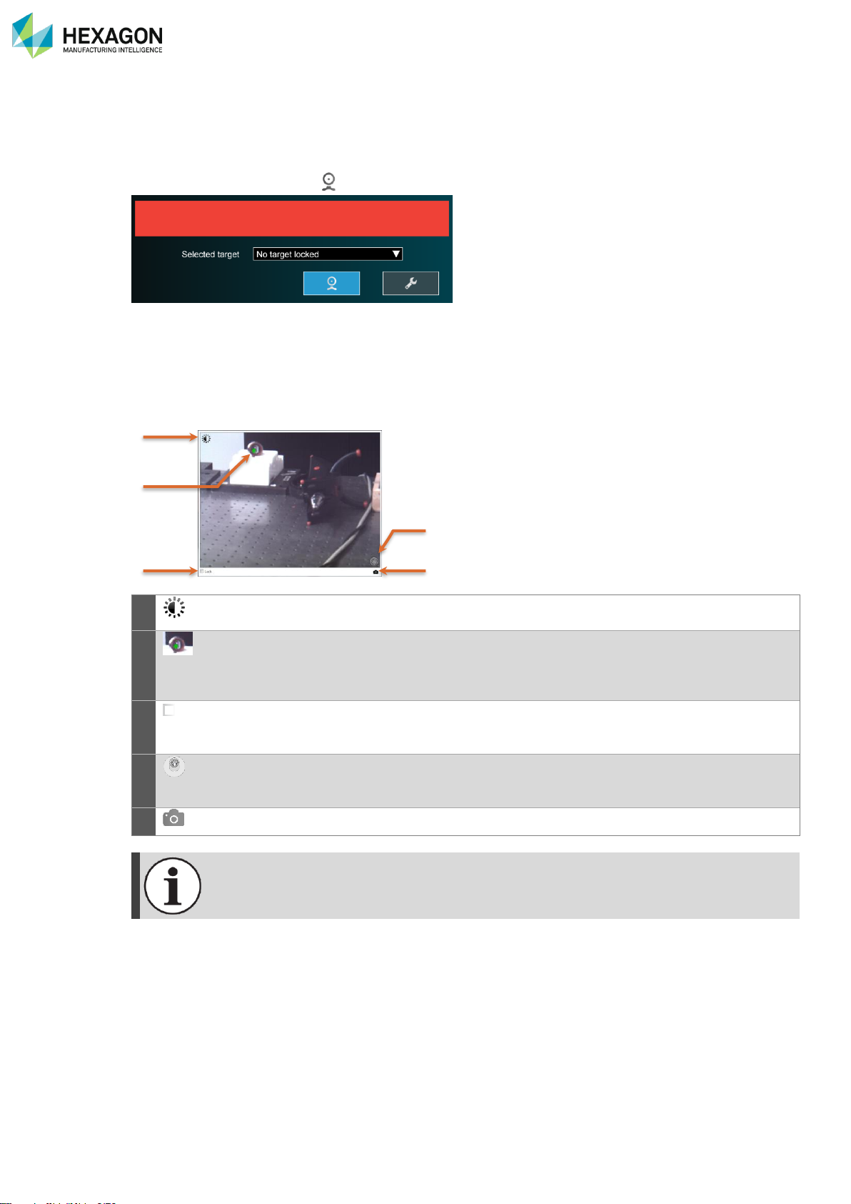
Tracker tools
H000002007-RDS User Manual │Version 5.0.0 (2018-09-17) │93
E.1 FIND A TARGET - OVC
Once the tracker is connected, and active, it has to focus on the target (Reflector, T-Probe or Scanner).
Either manually bring the target into the field of view of the tracker, or help and guide the tracker to the
target: Click on “Show OVC” ( ).
E.1.1 DESCRIPTION
The Overview Camera (OVC) provides a coloured video stream in order to locate targets.
The video gets displayed on screen:
a. Control of the contrast
b. Marked target
c. Activate the lock on the target
d. Dynamic control of the tracker position
e. Save the video in a picture file
a
Brightness: adjust the brightness of the view image by moving the slider. This setting
will be stored persistently.
b
Target: the OVC image contains for each reflector in the field of view (FoV) a green
spot.
Green spots for each reflector in the FoV are present all the time regardless if the
Absolute Tracker AT960 is locked or not to a target.
c
Lock
Lock option: auto–locking action on the click of the mouse or on closing the OVC.
When active, the Tracker will drive the beam to the click position and will perform a
relative search to lock onto a target.
d
Dynamic control: Drag the button on the panel to move the Tracker. The speed
increases the further the button is moved away from the centre.
Release the button to stop the movement.
e Saves the video of the OVC in a picture file.
The OVC can only be opened if the Absolute Tracker AT960 is initialized.
The Locking status depends if a target is locked or not when the OVC is opened.
No valid target has been found
a
b c e
d
Page 95
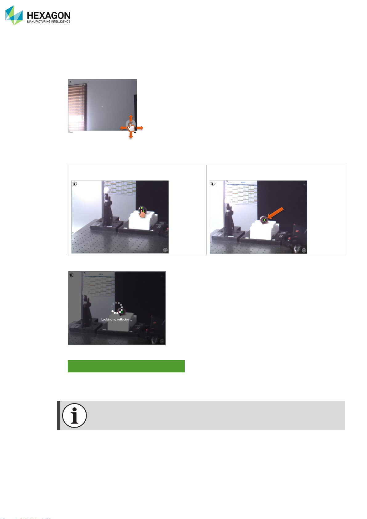
Tracker tools
H000002007-RDS User Manual │Version 5.0.0 (2018-09-17) │94
E.1.2 HOW TO FIND AND LOCK A TARGET
The purpose is to move the video in sort of placing the target at the middle of the view.
1. If not, enable the Lock option (bottom left).
2. Move the pointer on the hand (bottom right), then move the hand to get the view on the target.
3. Once the target appears on the video, affine the position by clicking at the centre of the target: only one
green dot is displayed on the target.
The target is not centred correctly: two green
dots are displayed: click on the target.
The view gets centred on the click point. Only
one dot is displayed.
4. If “Lock” is enabled, the tracker automatically adjusts and locks target.
5. Once the target is locked, RDS indicates
6. Close the OVC
It is possible to take measurements with the OVC window open.
Tracker is ready to measure
Page 96
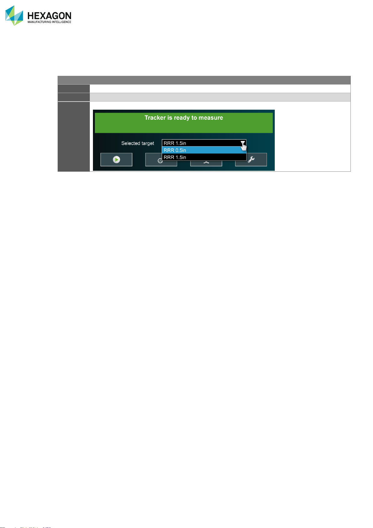
Tracker tools
H000002007-RDS User Manual │Version 5.0.0 (2018-09-17) │95
E.2 SELECT A TARGET
Different kinds of measurement targets can be used: T-Probe and Scanner are automatically recognized,
no need to select. The SMR reflectors cannot be recognized and require to be selected in the list.
Target
Selection
T-Probe
Automatic
Scanner
Automatic (see RDS Control Panel and RDS Scanning window for details)
Reflector
Select the appropriate reflector type in the list:
Page 97
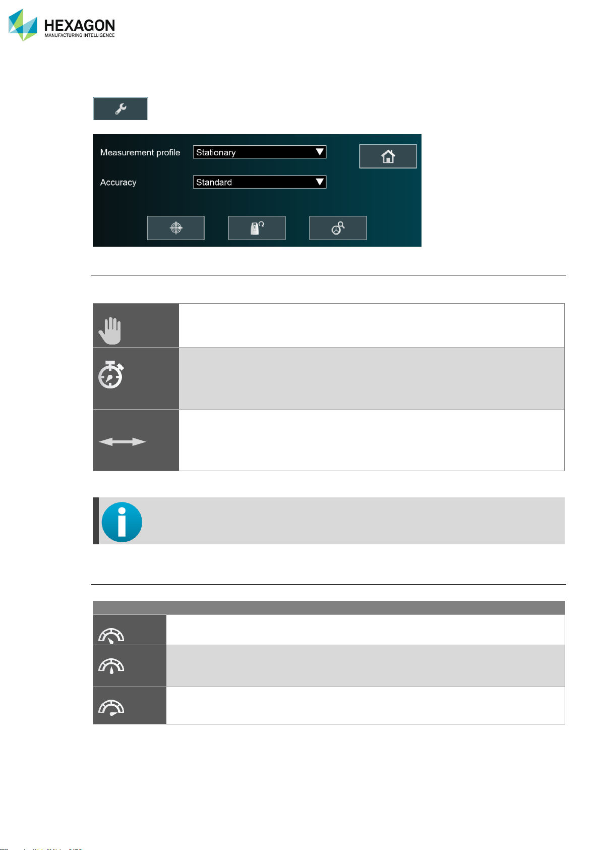
Tracker tools
H000002007-RDS User Manual │Version 5.0.0 (2018-09-17) │96
E.3 SETTINGS
To access the Tracker settings, click on the button
Measurement profile
The measurement profile enables the user to select the adequate measurement behaviour according the
application needs.
Stationary
(default)
This is the standard manual way to measure: point by point, each point is measured
independently.
Continuous time
Frequency controlled scan probing: points are automatically triggered on a frequency
defined with a specified period.
The space between each point depends on the speed of movement: the faster it is,
the more spaced the points are.
The delay between each point can then be specified (default 500ms)
Continuous
distance
Interval controlled scan probing: points are automatically triggered at a specified
distance from the previous point.
The space between each point is constant and does not depend on the speed of
movement.
The distance between each point can then be specified (default 1mm)
Another probing option is available on the home screen to enable the triggering of the point
based on the stability of the probe: see next chapter.
Accuracy
The accuracy defines the time of taking points: the slower it is, the more accurate.
Recommended usage
Fast
With this mode, the delay for each point is
reduced, however, it means less accurate.
Typically achieves specified
accuracy in controlled environment.
Standard
(default)
This is the standard mode, a compromise
between speed and accuracy.
Achieves specified accuracy.
Precise
With this mode, the time to take each point is
longer, but it provides a higher accuracy.
For sensors checks or compensations.
Highest accuracy. Sensor checks
and compensations.
Page 98
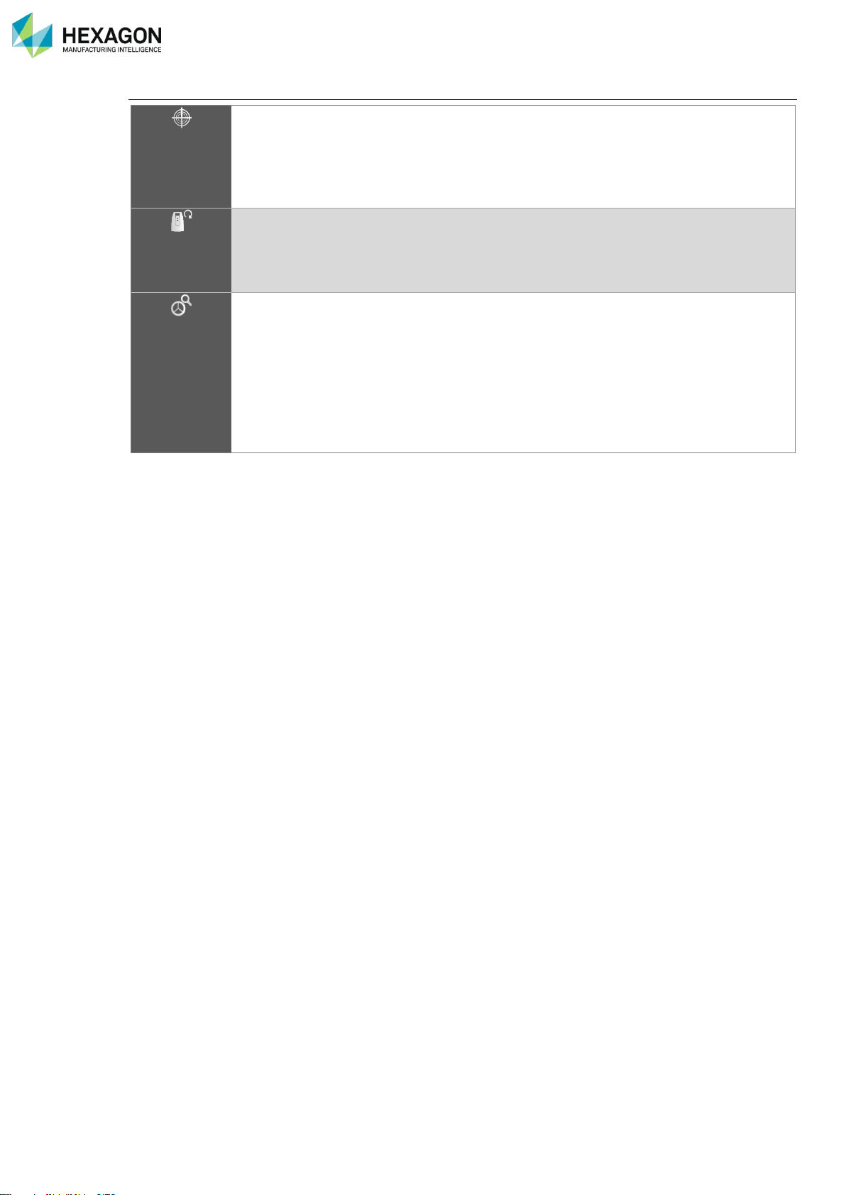
Tracker tools
H000002007-RDS User Manual │Version 5.0.0 (2018-09-17) │97
Buttons
PowerLock
PowerLock allows the system to detect when a reflector is in view of the
AT960 and automatically locks onto it without operator intervention.
The field of view of PowerLock is 10°, which corresponds to a spot size
of 1750 x 1750 mm at a distance of 10 meters.
When PowerLock is enabled, the tracker moves automatically to lock
onto the reflector when it is on the field of view.
Initialize
At start-up, the system is automatically initialized. During the initialization
process, all the subsystems in the Absolute Tracker AT960 are initialized
and are verified to be functional. During the initialization process the
sensor moves to safety position. Once the system is ready it will return
back to its initial position.
Find reflector
The Find Reflector function searches for a reflector within a defined
search area and locks onto a target found.
The search pattern depends on the target type, the distance and on the
PowerLock state [On/Off]:
• Off: during the search the Absolute Tracker AT960 moves in a
square spiral pattern to find a reflector. The Absolute Tracker AT960
will lock on automatically when the target position is within the
search area.
• On: the PowerLock automatically locks the marked target.
Page 99
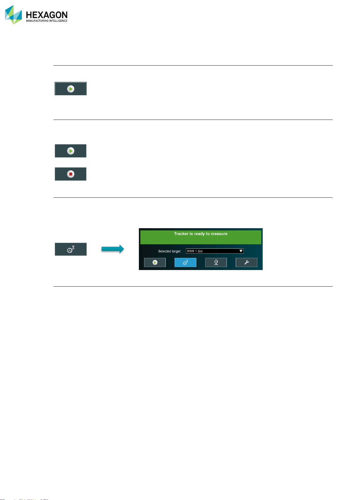
Tracker tools
H000002007-RDS User Manual │Version 5.0.0 (2018-09-17) │98
E.4 MEASURE WITH THE TRACKER
Manual probing (default)
When the measurement profile is set to “Stationary”, the points are taken independently from the others:
position the probe (SMR or T-Probe), and click on the button (or press the A button on the T-Probe):
A single point is then taken.
Scan probing
When the measurement profile is set to “Continuous time” or “Continuous distance”, the points are triggered
automatically once the specified delay or distance is reached after the previous point.
Press the Measure button to start the automatic measurement
,
Then press the Stop button to pause.
Stable probing (SMR only)
RDS provides the ability to trigger automatically a point when the probe stops moving: no need to press
any button, move the probe to the desired position, as soon as it becomes stable, the point is automatically
taken.
To activate the Stable measurement, press the button
Laser scanning
Please refer to the chapter Scanner for details on the use of the scanner.
Page 100
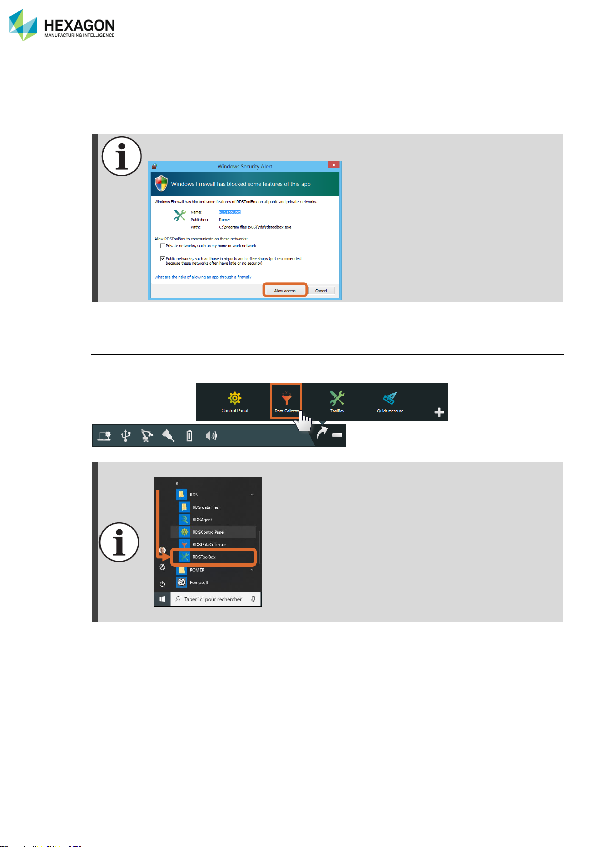
RDS Toolbox (arms only)
H000002007-RDS User Manual │Version 5.0.0 (2018-09-17) │99
F. RDS TOOLBOX (ARMS ONLY)
F.1 PRESENTATION
Windows® firewall must allow RDS Toolbox to communicate with networks.
When Windows® prompt the security alert, click on “Allow Access”
RDS Toolbox is a part of RDS package and is globally dedicated to the maintenance of the arm.
Open RDS Toolbox
To access RDS Toolbox, open the RDS Agent (RDS icon on the notification bar) and select “RDS Toolbox”
in the links.
RDS Toolbox can be also opened from “start menu > Programs > RDS > RDS Toolbox”
Fig. 2 : RDS Toolbox start Menu Windows®
 Loading...