

LASERJET PRO 500 COLOR MFP
Repair Manual
M570


HP LaserJet Pro 500 color MFP M570
Printers
Repair Manual

Copyright and License
© 2012 Copyright Hewlett-Packard
Development Company, L.P.
Reproduction, adaptation, or translation
without prior written permission is
prohibited, except as allowed under the
copyright laws.
The information contained herein is subject
to change without notice.
The only warranties for HP products and
services are set forth in the express warranty
statements accompanying such products and
services. Nothing herein should be
construed as constituting an additional
warranty. HP shall not be liable for technical
or editorial errors or omissions contained
herein.
Edition 1, 11/2012
Part number: CZ271-91020

Conventions used in this guide
TIP: Tips provide helpful hints or shortcuts.
NOTE: Notes provide important information to explain a concept or to complete a task.
CAUTION: Cautions indicate procedures that you should follow to avoid losing data or damaging
the product.
WARNING! Warnings alert you to specific procedures that you should follow to avoid personal
injury, catastrophic loss of data, or extensive damage to the product.
ENWW iii

iv Conventions used in this guide ENWW

Table of contents
1 Removal and replacement ................................................................................................ 1
Introduction ............................................................................................................................. 2
Removal and replacement strategy ............................................................................................. 2
General cautions during removal and replacement ........................................................ 2
Electrostatic discharge ............................................................................................... 3
Required tools ........................................................................................................... 3
Types of screws ........................................................................................................ 4
Service approach ..................................................................................................................... 5
Before performing service .......................................................................................... 5
After performing service ............................................................................................. 5
Post-service test ......................................................................................................... 6
Print-quality test .......................................................................................... 6
Copy-quality test ........................................................................................ 6
DC controller PCA ..................................................................................................... 7
Parts removal order ................................................................................................... 8
Removal and replacement procedures ........................................................................................ 9
Customer self repair (CSR) components ........................................................................ 9
Toner cartridges ......................................................................................... 9
Duplex-reverse guide ................................................................................ 11
Toner-collection unit .................................................................................. 12
Tray 2 and 3 ........................................................................................... 14
Pickup roller and separation pad (Tray 1) ................................................... 15
Pickup roller (Tray 2) ................................................................................ 17
Pickup and feed rollers (Tray 3) .................................................................. 19
Separation roller (Tray 2) .......................................................................... 21
Secondary transfer roller ........................................................................... 22
Reinstall the transfer roller ........................................................... 23
Intermediate transfer belt (ITB) .................................................................... 24
Front-door assembly ................................................................................. 27
Document feeder pickup rollers .................................................................. 28
Document feeder separation pad ............................................................... 31
Control panel .......................................................................................... 32
ENWW v

Remove the control panel ........................................................... 32
USB PCA ................................................................................................ 36
Remove the USB PCA ................................................................ 36
Control panel friction mount ...................................................................... 38
Remove the control panel friction mount ....................................... 38
Right door (optional paper feeder) ............................................................. 39
External panels, covers, and doors ............................................................................ 41
Identification and location ......................................................................... 41
Front-upper cover ..................................................................................... 42
Remove the front-upper cover ...................................................... 42
Right-door assembly ................................................................................. 44
Right-rear cover ........................................................................................ 48
Left cover ................................................................................................ 50
Rear-upper cover ...................................................................................... 53
Left-upper cover ........................................................................................ 54
Remove the left-upper cover ........................................................ 54
Right-upper rear cover .............................................................................. 55
Remove the right-upper cover ...................................................... 55
Rear cover ............................................................................................... 56
Remove the rear cover ............................................................... 56
Right-front cover ....................................................................................... 58
Remove the right-front cover ........................................................ 58
Delivery cover .......................................................................................... 62
Remove the delivery cover .......................................................... 62
Right-top cover ......................................................................................... 64
Remove the right-top cover ......................................................... 64
Upper-right cover ..................................................................................... 66
Remove the upper-right cover ...................................................... 66
Front-top cover ......................................................................................... 69
Remove the front-top cover ......................................................... 69
Rear-top cover ......................................................................................... 71
Remove the rear-top cover .......................................................... 72
Document feeder and scanner .................................................................................. 73
Document feeder ...................................................................................... 73
Reinstall the document feeder ...................................................... 76
Image scanner ......................................................................................... 77
Remove the image scanner ......................................................... 77
Reinstall the image scanner ........................................................ 80
Internal assemblies .................................................................................................. 81
Fuser ...................................................................................................... 81
Formatter PCA ......................................................................................... 83
vi ENWW

Remove the formatter PCA .......................................................... 83
Fax PCA ................................................................................................. 85
Remove the fax PCA and cable ................................................... 85
Wireless PCA .......................................................................................... 87
Remove the wireless PCA ........................................................... 87
Interconnect board (ICB) ........................................................................... 88
Remove the ICB ......................................................................... 88
DC controller PCA and tray ....................................................................... 91
Remove the DC controller PCA and tray ....................................... 91
Low-voltage power supply (LVPS) ................................................................ 94
Remove the LVPS ....................................................................... 94
Delivery fan, cartridge fan, and environmental sensor ................................... 99
Remove the delivery fan, cartridge fan, and environmental sensor ... 99
Toner-collection sensor ............................................................................ 104
Remove the toner-collection sensor ............................................. 104
Residual-toner-feed motor ........................................................................ 107
Remove the residual-toner-feed motor ......................................... 107
Secondary transfer assembly ................................................................... 112
Reinstall the secondary transfer assembly ................................... 113
Lower pickup guide ................................................................................ 114
Remove the lower pickup guide ................................................ 114
Reinstall the lower pickup guide ................................................ 116
Registration density (RD) sensor assembly .................................................. 117
Remove the RD sensor assembly ................................................ 117
Power-supply fan and fan duct ................................................................. 121
Remove the power-supply fan and fan duct ................................. 121
Registration assembly ............................................................................. 124
Remove the registration assembly .............................................. 124
High-voltage power supply lower ............................................................. 129
Remove the high-voltage power supply lower .............................. 129
Developing-disengagement motor ............................................................. 132
Remove the developing-disengagement motor ............................. 132
Pickup motor .......................................................................................... 134
Remove the pickup motor ......................................................... 134
Lifter-drive assembly ................................................................................ 135
Remove the lifter-drive assembly ................................................ 135
Tray-pickup drive assembly ...................................................................... 137
Remove the tray-pickup drive assembly ...................................... 137
Tray-pickup assembly .............................................................................. 144
Remove the tray-pickup assembly .............................................. 144
Laser/scanner assembly (Y/M) ................................................................ 146
ENWW vii

Remove the laser/scanner assembly (Y/M) ................................. 146
Laser/scanner assembly (C/Bk) ............................................................... 153
Remove the laser/scanner assembly (C/Bk) ................................ 154
High-voltage power supply upper ............................................................. 161
Remove the high-voltage power supply upper ............................. 161
Drum motor 1 ........................................................................................ 165
Remove the drum motor 1 ........................................................ 165
Drum motor 2 or drum motor 3 ................................................................ 166
Remove the drum motor 2 or drum motor 3 ................................ 166
Fuser motor ........................................................................................... 167
Remove the fuser motor ............................................................ 167
Main-drive assembly ............................................................................... 168
Remove the main-drive assembly ............................................... 169
Fuser-drive assembly ............................................................................... 179
Remove the fuser-drive assembly ............................................... 180
Delivery assembly .................................................................................. 184
Remove the delivery assembly ................................................... 185
Duplex-drive assembly ............................................................................ 189
Remove the duplex-drive assembly ............................................. 190
Optional paper feeder assembly (Tray 3) .................................................. 191
Drawer connector .................................................................... 191
2 Parts and diagrams ...................................................................................................... 193
Order parts, accessories, and supplies ................................................................................... 194
Oderable parts .................................................................................................................... 195
Accessories .......................................................................................................... 195
Print cartridges and toner collection unit ................................................................... 196
Customer self repair (CSR) and service kits ............................................................... 197
Whole unit replacment (WUR) ............................................................................................... 199
Service parts ....................................................................................................................... 200
Related documentation and software ...................................................................................... 202
Fasteners used in this product ................................................................................................ 202
How to use the parts lists and diagrams .................................................................................. 203
Assembly locations ............................................................................................................... 204
Base product (no optional trays or accessories) ......................................................... 204
Base product (optional trays or accessories) ............................................................. 205
Covers ................................................................................................................................ 206
Right-door assembly ............................................................................................................. 208
Internal assemblies ............................................................................................................... 210
Internal assemblies (1 of 6) ..................................................................................... 210
Internal assemblies (2 of 6) ..................................................................................... 212
viii ENWW

Internal assemblies (3 of 6) ..................................................................................... 214
Internal assemblies (4 of 6) ..................................................................................... 216
Internal assemblies (5 of 6) ..................................................................................... 218
Internal assemblies (6 of 6) ..................................................................................... 220
Assessories .......................................................................................................................... 222
1 x 500-sheet paper feeder .................................................................................... 222
Paper feeder covers ............................................................................................... 224
Paper feeder main body ........................................................................................ 226
Paper feeder tray .................................................................................................. 228
Paper feeder PCA ................................................................................................. 230
Alphabetical parts list ........................................................................................................... 232
Numerical parts list .............................................................................................................. 238
Index ............................................................................................................................... 245
ENWW ix

x ENWW

List of tables
Table 1-1 DC controller connectors ......................................................................................................... 7
Table 1-2 Product base, external panels, covers, doors; identification and location ..................................... 41
Table 2-1 Accessories ....................................................................................................................... 195
Table 2-2 LaserJet Pro 500 Color MFP M570dn (WUR) ......................................................................... 199
Table 2-3 LaserJet Pro 500 Color MFP M570dw (WUR) ........................................................................ 199
Table 2-4 Service parts ...................................................................................................................... 200
Table 2-5 Related documentation and software .................................................................................... 202
Table 2-6 Common fasteners ............................................................................................................. 202
Table 2-7 Optional 500-sheet input tray .............................................................................................. 205
Table 2-8 External covers, panels, and doors ....................................................................................... 207
Table 2-9 Right-door assembly ............................................................................................................ 209
Table 2-10 Internal assemblies (1 of 6) ................................................................................................ 211
Table 2-11 Internal assemblies (2 of 6) ................................................................................................ 213
Table 2-12 Internal assemblies (3 of 6) ................................................................................................ 215
Table 2-13 Internal assemblies (4 of 6) ................................................................................................ 217
Table 2-14 Internal assemblies (5 of 6) ................................................................................................ 219
Table 2-15 Internal assemblies (6 of 6) ................................................................................................ 221
Table 2-16 1 x 500-sheet paper feeder ............................................................................................... 223
Table 2-17 Paper feeder covers .......................................................................................................... 225
Table 2-18 Paper feeder main body .................................................................................................... 227
Table 2-19 Tray ................................................................................................................................ 229
Table 2-20 Paper feeder PCA ............................................................................................................ 231
Table 2-21 Alphabetical parts list ....................................................................................................... 232
Table 2-22 Numerical parts list ........................................................................................................... 238
ENWW xi

xii ENWW

List of figures
Figure 1-1 Phillips and Pozidriv screwdriver comparison ............................................................................ 3
Figure 1-2 DC controller PCA ................................................................................................................. 7
Figure 1-3 Remove the toner cartridge (1 of 2) ......................................................................................... 9
Figure 1-4 Remove the toner cartridge (2 of 2) ....................................................................................... 10
Figure 1-5 Remove the duplex-reverse guide (1 of 2) ............................................................................... 11
Figure 1-6 Remove the duplex-reverse guide (2 of 2) ............................................................................... 11
Figure 1-7 Remove the toner-collection unit (1 of 4) ................................................................................. 12
Figure 1-8 Remove the toner-collection unit (2 of 4) ................................................................................. 12
Figure 1-9 Remove the toner-collection unit (3 of 4) ................................................................................. 13
Figure 1-10 Remove the toner-collection unit (4 of 4) ............................................................................... 13
Figure 1-11 Remove Tray 2 and 3 (1 of 2) ............................................................................................. 14
Figure 1-12 Remove Tray 2 and 3 (2 of 2) ............................................................................................. 14
Figure 1-13 Remove the pickup roller and separation pad (Tray 1) (1 of 3) ................................................ 15
Figure 1-14 Remove the pickup roller and separation pad (Tray 1) (2 of 3) ................................................ 15
Figure 1-15 Remove the pickup roller and separation pad (Tray 1) (3 of 3) ................................................ 16
Figure 1-16 Remove the pickup roller (Tray 2) (1 of 4) ............................................................................. 17
Figure 1-17 Remove the pickup roller (Tray 2) (2 of 4) ............................................................................. 17
Figure 1-18 Remove the pickup roller (Tray 2) (3 of 4) ............................................................................. 18
Figure 1-19 Remove the pickup roller (Tray 2) (4 of 4) ............................................................................. 18
Figure 1-20 Remove the pickup and feed rollers (Tray 3) (1 of 2) .............................................................. 19
Figure 1-21 Remove the pickup and feed rollers (Tray 3) (2 of 2) .............................................................. 20
Figure 1-22 Remove the separation roller (Tray 2) ................................................................................... 21
Figure 1-23 Remove the transfer roller (1 of 3) ....................................................................................... 22
Figure 1-24 Remove the transfer roller (2 of 3) ....................................................................................... 22
Figure 1-25 Remove the transfer roller (3 of 3) ....................................................................................... 23
Figure 1-26 Reinstall the transfer roller ................................................................................................... 23
Figure 1-27 Remove the intermediate transfer belt (1 of 4) ....................................................................... 24
Figure 1-28 Remove the intermediate transfer belt (2 of 4) ....................................................................... 24
Figure 1-29 Remove the intermediate transfer belt (3 of 4) ....................................................................... 25
Figure 1-30 Remove the intermediate transfer belt (4 of 4) ....................................................................... 26
Figure 1-31 Remove the front-door assembly (1 of 2) ............................................................................... 27
Figure 1-32 Remove the front-door a
ssembly (2 of 2) ............................................................................... 27
ENWW xiii

Figure 1-33 Remove the document feeder pickup rollers (1 of 5) ............................................................... 28
Figure 1-34 Remove the document feeder pickup rollers (2 of 5) ............................................................... 28
Figure 1-35 Remove the document feeder pickup rollers (3 of 5) ............................................................... 29
Figure 1-36 Remove the document feeder pickup rollers (4 of 5) ............................................................... 29
Figure 1-37 Remove the document feeder pickup rollers (5 of 5) ............................................................... 30
Figure 1-38 Remove the document feeder separation pad (1 of 2) ............................................................ 31
Figure 1-39 Remove the document feeder separation pad (2 of 2) ............................................................ 31
Figure 1-40 Remove the control panel (1 of 6) ........................................................................................ 32
Figure 1-41 Remove the control panel (2 of 6) ........................................................................................ 33
Figure 1-42 Remove the control panel (3 of 6) ........................................................................................ 33
Figure 1-43 Remove the control panel (4 of 6) ........................................................................................ 34
Figure 1-44 Remove the control panel (5 of 6) ........................................................................................ 34
Figure 1-45 Remove the control panel (6 of 6) ........................................................................................ 35
Figure 1-46 Remove the USB PCA (1 of 3) ............................................................................................. 36
Figure 1-47 Remove the USB PCA (2 of 3) ............................................................................................. 37
Figure 1-48 Remove the USB PCA (3 of 3) ............................................................................................. 37
Figure 1-49 Remove the control panel friction mount ............................................................................... 38
Figure 1-50 Remove the right door; optional paper feeder (1 of 3) ........................................................... 39
Figure 1-51 Remove the right door; optional paper feeder (2 of 3) ........................................................... 39
Figure 1-52 Remove the right door; optional paper feeder (3 of 3) ........................................................... 40
Figure 1-53 Product base, external panels, covers, doors; identification and location .................................. 41
Figure 1-54 Remove the front-upper cover (1 of 4) .................................................................................. 42
Figure 1-55 Remove the front-upper cover (2 of 4) .................................................................................. 42
Figure 1-56 Remove the front-upper cover (3 of 4) .................................................................................. 43
Figure 1-57 Remove the front-upper cover (4 of 4) .................................................................................. 43
Figure 1-58 Remove the right-door assembly (1 of 8) ............................................................................... 44
Figure 1-59 Remove the right-door assembly (2 of 8) ............................................................................... 44
Figure 1-60 Remove the right-door assembly (3 of 8) ............................................................................... 45
Figure 1-61 Remove the right-door assembly (4 of 8) ............................................................................... 45
Figure 1-62 Remove the right-door assembly (5 of 8) ............................................................................... 46
Figure 1-63 Remove the right-door assembly (6 of 8) .....
Figure 1-64 Remove the right-door assembly (7 of 8) ............................................................................... 47
Figure 1-65 Remove the right-door assembly (8 of 8) ............................................................................... 47
Figure 1-66 Remove the right-rear cover (1 of 3) ..................................................................................... 48
Figure 1-67 Remove the right-rear cover (2 of 3) ..................................................................................... 48
Figure 1-68 Remove the right-rear cover (3 of 3) ..................................................................................... 49
Figure 1-69 Remove the left cover (1 of 5) ............................................................................................. 50
Figure 1-70 Remove the left cover (2 of 5) ............................................................................................. 50
Figure 1-71 Remove the left cover (3 of 5) ............................................................................................. 51
Figure 1-72 Remove the left cover (4 of 5) ............................................................................................. 51
Figure 1-73 Remove the left cover (5 of 5) ............................................................................................. 52
.......................................................................... 46
xiv ENWW

Figure 1-74 Remove the rear-upper cover (1 of 2) ................................................................................... 53
Figure 1-75 Remove the rear-upper cover (2 of 2) ................................................................................... 53
Figure 1-76 Remove the left-upper cover ................................................................................................ 54
Figure 1-77 Remove the right-upper cover .............................................................................................. 55
Figure 1-78 Remove the rear cover (1 of 2) ............................................................................................ 56
Figure 1-79 Remove the rear cover (2 of 2) ............................................................................................ 57
Figure 1-80 Remove the right-front cover (1 of 5) .................................................................................... 58
Figure 1-81 Remove the right-front cover (2 of 5) .................................................................................... 59
Figure 1-82 Remove the right-front cover (3 of 5) .................................................................................... 59
Figure 1-83 Remove the right-front cover (4 of 5) .................................................................................... 60
Figure 1-84 Remove the right-front cover (5 of 5) .................................................................................... 60
Figure 1-85 Reinstall the power button ................................................................................................... 61
Figure 1-86 Remove the delivery cover (1 of 3) ...................................................................................... 62
Figure 1-87 Remove the delivery cover (2 of 3) ...................................................................................... 63
Figure 1-88 Remove the delivery cover (3 of 3) ...................................................................................... 63
Figure 1-89 Remove the right-top cover (1 of 2) ...................................................................................... 64
Figure 1-90 Remove the right-top cover (2 of 2) ...................................................................................... 65
Figure 1-91 Remove the upper-right cover (1 of 5) .................................................................................. 66
Figure 1-92 Remove the upper-right cover (2 of 5) .................................................................................. 67
Figure 1-93 Remove the upper-right cover (3 of 5) .................................................................................. 67
Figure 1-94 Remove the upper-right cover (4 of 5) .................................................................................. 68
Figure 1-95 Remove the upper-right cover (5 of 5) .................................................................................. 68
Figure 1-96 Remove the front-top cover (1 of 2) ...................................................................................... 69
Figure 1-97 Remove the front-top cover (2 of 2) ...................................................................................... 70
Figure 1-98 Remove the rear-top cover .................................................................................................. 72
Figure 1-99 Remove the document feeder assembly (1 of 4) ..................................................................... 73
Figure 1-100 Remove the document feeder assembly (2 of 4) ................................................................... 74
Figure 1-101 Remove the document feeder assembly (3 of 4) ................................................................... 74
Figure 1-102 Remove the document feeder assembly (4 of 4) ................................................................... 75
Figure 1-103 Remove the image scanner (1 of 5) ................................................................................... 77
Figure 1-104 Remove the image scanner (2 of 5) ................................................................................... 78
Figure 1-105 Remove the image scanner (3 of 5) ................................................................................... 78
Figure 1-106 Remove the image scanner (4 of 5) ................................................................................... 79
Figure 1-107 Remove the image scanner (5 of 5) ................................................................................... 79
Figure 1-
Figure 1-109 Remove the fuser (2 of 2) ................................................................................................. 82
Figure 1-110 Remove the formatter (1 of 2) ............................................................................................ 83
Figure 1-111 Remove the formatter (2 of 2) ............................................................................................ 84
Figure 1-112 Remove the fax PCA (1 of 2) ............................................................................................ 85
Figure 1-113 Remove the fax PCA (2 of 2) ............................................................................................ 86
Figure 1-114 Remove the wireless PCA ................................................................................................. 87
108 Remove the fuser (1 of 2) ................................................................................................. 81
ENWW xv

Figure 1-115 Remove the ICB (1 of 4) ................................................................................................... 88
Figure 1-116 Remove the ICB (2 of 4) ................................................................................................... 89
Figure 1-117 Remove the ICB (3 of 4) ................................................................................................... 89
Figure 1-118 Remove the ICB (4 of 4) ................................................................................................... 90
Figure 1-119 Remove the DC controller PCA and tray (1 of 4) ................................................................. 91
Figure 1-120 Remove the DC controller PCA and tray (2 of 4) ................................................................. 92
Figure 1-121 Remove the DC controller PCA and tray (3 of 4) ................................................................. 92
Figure 1-122 Remove the DC controller PCA and tray (4 of 4) ................................................................. 93
Figure 1-123 Remove the LVPS (1 of 8) ................................................................................................. 94
Figure 1-124 Remove the LVPS (2 of 8) ................................................................................................. 95
Figure 1-125 Remove the LVPS (3 of 8) ................................................................................................. 95
Figure 1-126 Remove the LVPS (4 of 8) ................................................................................................. 96
Figure 1-127 Remove the LVPS (5 of 8) ................................................................................................. 96
Figure 1-128 Remove the LVPS (6 of 8) ................................................................................................. 97
Figure 1-129 Remove the LVPS (7 of 8) ................................................................................................. 97
Figure 1-130 Remove the LVPS (8 of 8) ................................................................................................. 98
Figure 1-131 Remove the delivery fan, cartridge fan, and environmental sensor (1 of 9) ............................. 99
Figure 1-132 Remove the delivery fan, cartridge fan, and environmental sensor (2 of 9) ........................... 100
Figure 1-133 Remove the delivery fan, cartridge fan, and environmental sensor (3 of 9) ........................... 100
Figure 1-134 Remove the delivery fan, cartridge fan, and environmental sensor (4 of 9) ........................... 101
Figure 1-135 Remove the delivery fan, cartridge fan, and environmental sensor (5 of 9) ........................... 101
Figure 1-136 Remove the delivery fan, cartridge fan, and environmental sensor (6 of 9) ........................... 102
Figure 1-137 Remove the delivery fan, cartridge fan, and environmental sensor (7 of 9) ........................... 102
Figure 1-138 Remove the delivery fan, cartridge fan, and environmental sensor (8 of 9) ........................... 103
Figure 1-139 Remove the delivery fan, cartridge fan, and environmental sensor (9 of 9) ........................... 103
Figure 1-140 Remove the toner-collection sensor (1 of 4) ....................................................................... 104
Figure 1-141 Remove the toner-collection sensor (2 of 4) ....................................................................... 105
Figure 1-142 Remove the toner-collection sensor (3 of 4) ....................................................................... 105
Figure 1-143 Remove the toner-collection sensor (4 of 4) ....................................................................... 106
Figure 1-144 Remove the residual-toner-feed motor (1 of 7) ................................................................... 107
Figure 1-145 Remove the residual-toner-feed motor (2 of 7) ..
Figure 1-146 Remove the residual-toner-feed motor (3 of 7) ................................................................... 108
Figure 1-147 Remove the residual-toner-feed motor (4 of 7) ................................................................... 109
Figure 1-148 Remove the residual-toner-feed motor (5 of 7) ................................................................... 109
Figure 1-149 Remove the residual-toner-feed motor (6 of 7) ................................................................... 110
Figure 1-150 Remove the residual-toner-feed motor (7 of 7) ................................................................... 110
Figure 1-151 Reinstall the residual-toner collection door ........................................................................ 111
Figure 1-152 Remove the secondary transfer assembly (1 of 3) .............................................................. 112
Figure 1-153 Remove the secondary transfer assembly (2 of 3) .............................................................. 112
Figure 1-154 Remove the secondary transfer assembly (3 of 3) .............................................................. 113
Figure 1-155 Reinstall the secondary transfer assembly ......................................................................... 113
................................................................. 108
xvi ENWW

Figure 1-156 Remove the lower pickup guide (1 of 4) ........................................................................... 114
Figure 1-157 Remove the lower pickup guide (2 of 4) ........................................................................... 114
Figure 1-158 Remove the lower pickup guide (3 of 4) ........................................................................... 115
Figure 1-159 Remove the lower pickup guide (4 of 4) ........................................................................... 115
Figure 1-160 Remove the RD sensor assembly (1 of 6) .......................................................................... 117
Figure 1-161 Remove the RD sensor assembly (2 of 6) .......................................................................... 118
Figure 1-162 Remove the RD sensor assembly (3 of 6) .......................................................................... 118
Figure 1-163 Remove the RD sensor assembly (4 of 6) .......................................................................... 119
Figure 1-164 Remove the RD sensor assembly (5 of 6) .......................................................................... 119
Figure 1-165 Remove the RD sensor assembly (6 of 6) .......................................................................... 120
Figure 1-166 Remove the power-supply fan (1 of 4) .............................................................................. 121
Figure 1-167 Remove the power-supply fan (2 of 4) .............................................................................. 122
Figure 1-168 Remove the power-supply fan (3 of 4) .............................................................................. 122
Figure 1-169 Remove the power-supply fan (4 of 4) .............................................................................. 123
Figure 1-170 Remove the registration assembly (1 of 8) ........................................................................ 124
Figure 1-171 Remove the registration assembly (2 of 8) ........................................................................ 125
Figure 1-172 Remove the registration assembly (3 of 8) ........................................................................ 125
Figure 1-173 Remove the registration assembly (4 of 8) ........................................................................ 126
Figure 1-174 Remove the registration assembly (5 of 8) ........................................................................ 126
Figure 1-175 Remove the registration assembly (6 of 8) ........................................................................ 127
Figure 1-176 Remove the registration assembly (7 of 8) ........................................................................ 127
Figure 1-177 Remove the registration assembly (8 of 8) ........................................................................ 128
Figure 1-178 Remove the high-voltage power supply lower (1 of 4) ........................................................ 129
Figure 1-179 Remove the high-voltage power supply lower (2 of 4) ........................................................ 130
Figure 1-180 Remove the high-voltage power supply lower (3 of 4) ........................................................ 130
Figure 1-181 Remove the high-voltage power supply lower (4 of 4) ........................................................ 131
Figure 1-182 Reinstall the high-voltage power supply lower ................................................................... 131
Figure 1-183 Remove the developing-disengagement motor (1 of 2) ....................................................... 132
Figure 1-184 Remove the developing-disengagement motor (2 of 2) ....................................................... 133
Figure 1-185 Remove the pickup motor ............................................................................................... 134
Figure 1-186 Remove the lifter-drive assembly (1 of 2) .......................................................................... 135
Figure 1-187 Remove the lifter-drive assembly (2 of 2) .......................................................................... 136
Figure 1-188 Remove the tray-pickup drive assembly (1 of 10) ............................................................... 137
Figure 1-189 Remove the tray-pickup drive assembly (2 of 10) ............................................................... 138
Figure 1-190 R
Figure 1-191 Remove the tray-pickup drive assembly (4 of 10) ............................................................... 139
Figure 1-192 Remove the tray-pickup drive assembly (5 of 10) ............................................................... 139
Figure 1-193 Remove the tray-pickup drive assembly (6 of 10) ............................................................... 140
Figure 1-194 Remove the tray-pickup drive assembly (7 of 10) ............................................................... 140
Figure 1-195 Remove the tray-pickup drive assembly (8 of 10) ............................................................... 141
Figure 1-196 Remove the tray-pickup drive assembly (9 of 10) ............................................................... 141
emove the tray-pickup drive assembly (3 of 10) ............................................................... 138
ENWW xvii

Figure 1-197 Remove the tray-pickup drive assembly (10 of 10) ............................................................. 142
Figure 1-198 Reinstall the tray-pickup drive assembly (1 of 3) ................................................................ 142
Figure 1-199 Reinstall the tray-pickup drive assembly (2 of 3) ................................................................ 143
Figure 1-200 Reinstall the tray-pickup drive assembly (3 of 3) ................................................................ 143
Figure 1-201 Remove the tray-pickup assembly (1 of 3) ......................................................................... 144
Figure 1-202 Remove the tray-pickup assembly (2 of 3) ......................................................................... 145
Figure 1-203 Remove the tray-pickup assembly (3 of 3) ......................................................................... 145
Figure 1-204 Remove the laser/scanner assembly (Y/M) (1 of 12) ......................................................... 146
Figure 1-205 Remove the laser/scanner assembly (Y/M) (2 of 12) ......................................................... 147
Figure 1-206 Remove the laser/scanner assembly (Y/M) (3 of 12) ......................................................... 147
Figure 1-207 Remove the laser/scanner assembly (Y/M) (4 of 12) ......................................................... 148
Figure 1-208 Remove the laser/scanner assembly (Y/M) (5 of 12) ......................................................... 148
Figure 1-209 Remove the laser/scanner assembly (Y/M) (6 of 12) ......................................................... 149
Figure 1-210 Remove the laser/scanner assembly (Y/M) (7 of 12) ......................................................... 149
Figure 1-211 Remove the laser/scanner assembly (Y/M) (8 of 12) ......................................................... 150
Figure 1-212 Remove the laser/scanner assembly (Y/M) (9 of 12) ......................................................... 150
Figure 1-213 Remove the laser/scanner assembly (Y/M) (10 of 12) ....................................................... 151
Figure 1-214 Remove the laser/scanner assembly (Y/M) (11 of 12) ....................................................... 151
Figure 1-215 Remove the laser/scanner assembly (Y/M) (12 of 12) ....................................................... 152
Figure 1-216 Remove the laser/scanner assembly (C/Bk) (1 of 7) .......................................................... 154
Figure 1-217 Remove the laser/scanner assembly (C/Bk) (2 of 7) .......................................................... 154
Figure 1-218 Remove the laser/scanner assembly (C/Bk) (3 of 7) .......................................................... 155
Figure 1-219 Remove the laser/scanner assembly (C/Bk) (4 of 7) .......................................................... 155
Figure 1-220 Remove the laser/scanner assembly (C/Bk) (5 of 7) .......................................................... 156
Figure 1-221 Remove the laser/scanner assembly (C/Bk) (6 of 7) .......................................................... 157
Figure 1-222 Remove the laser/scanner assembly (C/Bk) (7 of 7) .......................................................... 158
Figure 1-223 Reinstall the PGC actuators (1 of 5) ................................................................................. 158
Figure 1-224 R
Figure 1-225 Reinstall the PGC actuators (3 of 5) ................................................................................. 159
Figure 1-226 Reinstall the PGC actuators (4 of 5) ................................................................................. 160
Figure 1-227 Reinstall the PGC actuators (5 of 5) ................................................................................. 160
Figure 1-228 Remove the high-voltage power supply upper (1 of 5) ........................................................ 161
Figure 1-229 Remove the high-voltage power supply upper (2 of 5) ........................................................ 162
Figure 1-230 Remove the high-voltage power supply upper (3 of 5) ........................................................ 162
Figure 1-231 Remove the high-voltage power supply upper (4 of 5) ........................................................ 163
Figure 1-232 Remove the high-voltage power supply upper (5 of 5) ........................................................ 163
Figure 1-233 Reinstall the high-voltage power supply upper ................................................................... 164
Figure 1-234 Remove the drum motor 1 ............................................................................................... 165
Figure 1-235 Remove the drum motor 2 or drum motor 3 ...................................................................... 166
Figure 1-236 Remove the fuser motor .................................................................................................. 167
Figure 1-237 Remove the main-drive assembly (1 of 7) .......................................................................... 169
einstall the PGC actuators (2 of 5) ................................................................................. 159
xviii ENWW

Figure 1-238 Remove the main-drive assembly (2 of 7) .......................................................................... 169
Figure 1-239 Remove the main-drive assembly (3 of 7) .......................................................................... 170
Figure 1-240 Remove the main-drive assembly (4 of 7) .......................................................................... 170
Figure 1-241 Remove the main-drive assembly (5 of 7) .......................................................................... 171
Figure 1-242 Remove the main-drive assembly (6 of 7) .......................................................................... 171
Figure 1-243 Remove the main-drive assembly (7 of 7) .......................................................................... 172
Figure 1-244 Reinstall the main-drive assembly (1 of 11) ....................................................................... 173
Figure 1-245 Reinstall the main-drive assembly (2 of 11) ....................................................................... 173
Figure 1-246 Reinstall the main-drive assembly (3 of 11) ....................................................................... 174
Figure 1-247 Reinstall the main-drive assembly (4 of 11) ....................................................................... 174
Figure 1-248 Reinstall the main-drive assembly (5 of 11) ....................................................................... 175
Figure 1-249 Reinstall the main-drive assembly (6 of 11) ....................................................................... 176
Figure 1-250 Reinstall the main-drive assembly (7 of 11) ....................................................................... 176
Figure 1-251 Reinstall the main-drive assembly (8 of 11) ....................................................................... 177
Figure 1-252 Reinstall the main-drive assembly (9 of 11) ....................................................................... 177
Figure 1-253 Reinstall the main-drive assembly (10 of 11) ..................................................................... 178
Figure 1-254 Reinstall the main-drive assembly (11 of 11) ..................................................................... 178
Figure 1-255 Remove the fuser-drive assembly (1 of 6) .......................................................................... 180
Figure 1-256 Remove the fuser-drive assembly (2 of 6) .......................................................................... 180
Figure 1-257 Remove the fuser-drive assembly (3 of 6) .......................................................................... 181
Figure 1-258 Remove the fuser-drive assembly (4 of 6) .......................................................................... 181
Figure 1-259 Remove the fuser-drive assembly (5 of 6) .......................................................................... 182
Figure 1-260 Remove the fuser-drive assembly (6 of 6) .......................................................................... 182
Figure 1-261 Reinstall the fuser-drive assembly ..................................................................................... 183
Figure 1-262 Remove the delivery assembly (1 of 5) ............................................................................. 185
Figure 1-263 Remove the delivery assembly (2 of 5) ............................................................................. 185
Figure 1-264 Remove the delivery assembly (3 of 5) ............................................................................. 186
Figure 1-265 Remove the delivery assembly (4 of 5) ............................................................................. 186
Figure 1-266 Remove the delivery assembly (5 of 5) ............................................................................. 187
Figure 1-267 Reinstall the delivery assembly (1 of 2) ............................................................................. 188
Figure 1-268 Reinstall the delivery assembly (2 of 2) ............................................................................. 188
Figure 1-269 Re
Figure 1-270 Remove the duplex-drive assembly (2 of 2) ....................................................................... 190
Figure 1-271 Remove the drawer connector; optional paper feeder (1 of 2) ............................................ 191
Figure 1-272 Remove the drawer connector; optional paper feeder (2 of 2) ............................................ 192
Figure 2-1 Base product (no optional trays or accessories) ..................................................................... 204
Figure 2-2 Base product (optional trays or accessories) .......................................................................... 205
Figure 2-3 External covers, panels, and doors ...................................................................................... 206
Figure 2-4 Right-door assembly ........................................................................................................... 208
Figure 2-5 Internal assemblies (1 of 6) ................................................................................................. 210
Figure 2-6 Internal assemblies (2 of 6) ................................................................................................. 212
move the duplex-drive assembly (1 of 2) ....................................................................... 190
ENWW xix

Figure 2-7 Internal assemblies (3 of 6) ................................................................................................. 214
Figure 2-8 Internal assemblies (4 of 6) ................................................................................................. 216
Figure 2-9 Internal assemblies (5 of 6) ................................................................................................. 218
Figure 2-10 Internal assemblies (6 of 6) ............................................................................................... 220
Figure 2-11 1 x 500-sheet paper feeder .............................................................................................. 222
Figure 2-12 Paper feeder covers ......................................................................................................... 224
Figure 2-13 Paper feeder main body ................................................................................................... 226
Figure 2-14 Tray ............................................................................................................................... 228
Figure 2-15 Paper feeder PCA ........................................................................................................... 230
xx ENWW

1 Removal and replacement
NOTE: Your product might not appear exactly as the one shown in the photos in this chapter.
Although some photos do not show the ADF/scanner unit, the procedures in this chapter are
appropriate for your product.
Introduction
●
Removal and replacement strategy
●
Service approach
●
Removal and replacement procedures
●
ENWW 1

Introduction
This chapter describes the removal and replacement of field-replaceable units (FRUs) only.
Replacing FRUs is generally the reverse of removal. Occasionally, notes and tips are included to
provide directions for difficult or critical replacement procedures.
not
HP does
Note the length, diameter, color, type, and location of each screw. Be sure to return each screw to its
original location during reassembly.
Incorrectly routed or loose wire harnesses can interfere with other internal components and can become
damaged or broken. Frayed or pinched harness wires can be difficult to find. When replacing wire
harnesses, always use the provided wire loops, lance points, or wire-harness guides and retainers.
support repairing individual subassemblies or troubleshooting to the component level.
Removal and replacement strategy
General cautions during removal and replacement
This chapter describes the removal and replacement of field-replaceable units (FRUs) only.
Replacing FRUs is generally the reverse of removal. Occasionally, notes and tips are included to
provide directions for difficult or critical replacement procedures.
not
HP does
WARNING! Turn the product off, wait 5 seconds, and then remove the power cable before
attempting to service the product. If this warning is not followed, severe injury can result, in addition to
damage to the product. The power must be on for certain functional checks during troubleshooting.
However, disconnect the power supply during parts removal.
Never operate or service the product with the protective cover removed from the laser scanner
assembly. The reflected beam, although invisible, can damage your eyes.
The sheet-metal parts can have sharp edges. Be careful when handling sheet-metal parts.
CAUTION: Do not bend or fold the flat flexible cables (FFCs) during removal or installation. Also, do
not straighten prefolds in the FFCs. You
an FFC into a connector can cause a short circuit in a Printed Circuit Assembly (PCA).
Incorrectly routed or loose wire harnesses can interfere with other internal components and can become
damaged or broken. Frayed or pinched harness wires can be difficult to find. When replacing wire
harnesses, always use the provided wire loops, lance points, or wire-harness guides and retainers.
NOTE: To install a self-tapping screw, first turn it counterclockwise to align it with the thread pattern,
and then carefully turn it clockwise to tighten. Do not overtighten. If a self-tapping screw-hole becomes
stripped, repair the screw-hole or replace the affected assembly.
Note the length, diameter, color, type, and location of each screw. Be sure to return each screw to its
original location during reassembly.
support repairing individual subassemblies or troubleshooting to the component level.
must
fully seat all FFCs in their connectors. Failure to fully seat
2 Chapter 1 Removal and replacement ENWW
TIP: For clarity, some photos in this chapter might show components removed that would not be
removed to service the product. If necessary, remove the components listed at the beginning of a
procedure before proceeding to service the product.
Electrostatic discharge
CAUTION: Some parts are sensitive to electrostatic discharge (ESD). Look for the ESD reminder
when removing product parts. Always perform service work at an ESD-protected workstation or mat, or
use an ESD strap. If an ESD workstation, mat, or strap is not available, ground yourself by touching the
sheet-metal chassis
Protect the ESD-sensitive parts by placing them in ESD pouches when they are out of the product.
before
Required tools
#1 Phillips screwdriver with a magnetic tip and a 152-mm (6-inch) shaft length
●
#2 Phillips screwdriver with a magnetic tip and a 152-mm (6-inch) shaft length
●
Small flat blade screwdriver
●
Needle-nose pliers
●
touching an ESD-sensitive part.
ESD mat or ESD strap (if one is available)
●
Penlight (optional)
●
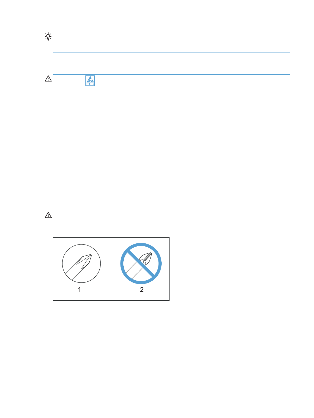
CAUTION: Always use a Phillips screwdriver (callout 1). Do not use a Pozidriv® screwdriver
(callout 2) or any motorized screwdriver. These can damage screws or screw threads.
Figure 1-1 Phillips and Pozidriv screwdriver comparison
ENWW
Removal and replacement strategy
3
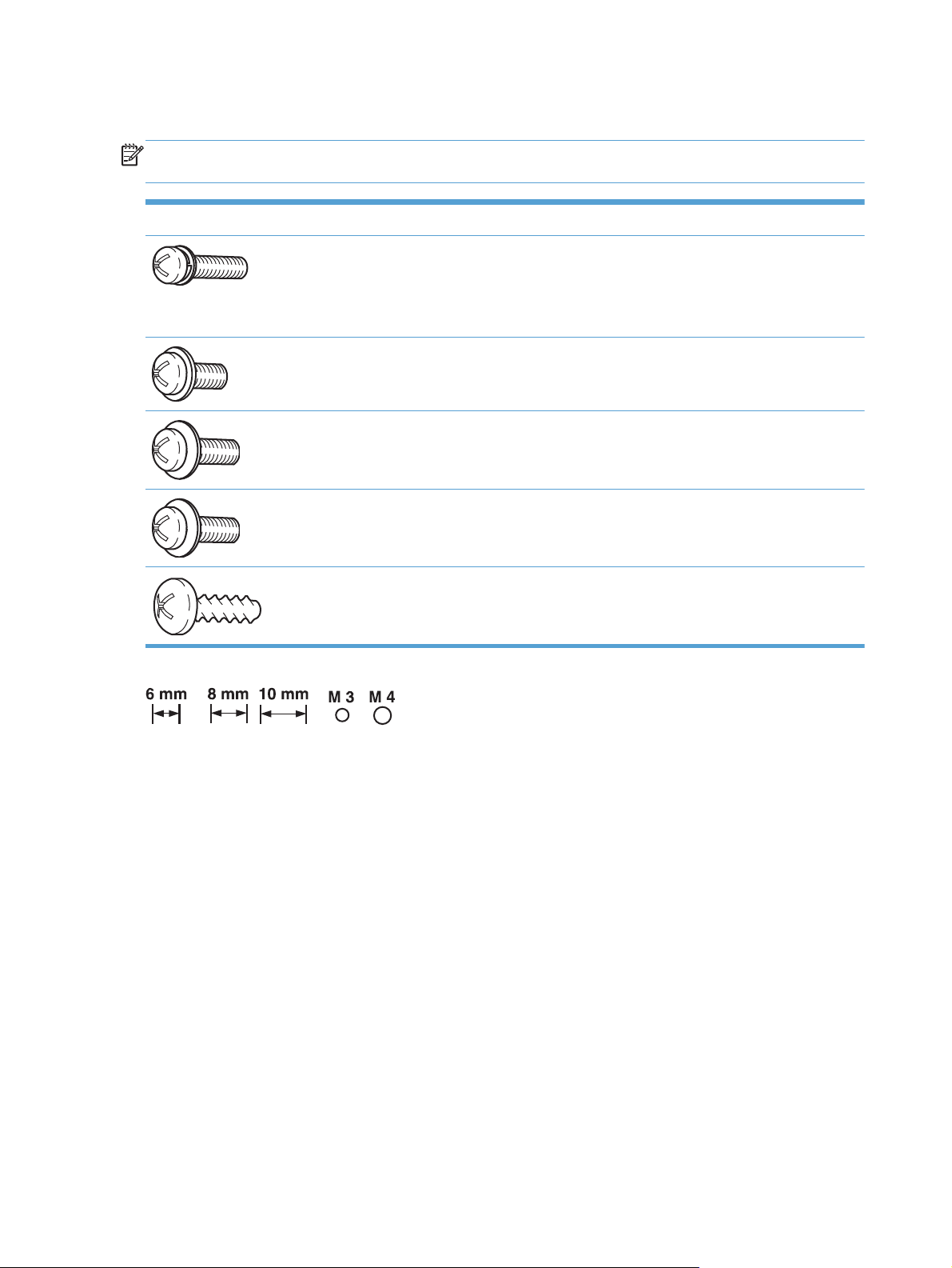
Types of screws
NOTE: The illustrations in this section are for reference only. The screws in your product might look
slightly different.
Illustration Description Size Part number Use
Screw with washer M3X6 XB2-7300-000CN Used to secure metal
components to metal
components (for
example, a ground
wire to the frame)
Screw, tapping M3X6 XA9-1503-000CN
Screw D-M3X6 XA9-1671-000CN
Screw P-M3X8 XB4-5300-807CN
Screw, tapping, truss
head
M4X10 XB4-7401-005CN Used to secure
anything to plastic
4 Chapter 1 Removal and replacement ENWW

Service approach
Product repair normally begins by using the product internal diagnostics and the following two-step
process:
1. Isolate the problem to the major system (for example, the network or server, or the product).
2. Troubleshoot the problem by using the procedures in the solve problems chapter.
After you find a faulty part, the product can usually be repaired at the assembly level by replacing fieldreplaceable units (FRUs). Some mechanical assemblies might need to be repaired at the subassembly
level.
Before performing service
Remove all media from the product.
●
Turn off the power using the power switch.
●
Unplug the power cable and interface cable or cables.
●
Place the product on an ESD workstation or mat, or use an ESD strap (if one is available). If an
●
ESD workstation, mat, or strap is not available, ground yourself by touching the sheet-metal
before
chassis
touching an ESD-sensitive part.
Remove the toner cartridges. See
●
Remove the tray or trays. See
●
After performing service
Plug in the power cable.
●
Reinstall the toner cartridges.
●
Reinstall the tray or trays.
●
If the optional paper feeder was installed, place the product on the feeder.
●
NOTE: Your product might not appear exactly as the one shown in the photos in this chapter.
Although some photos do not show the ADF/scanner unit, the procedures in this chapter are
appropriate for this product.
Toner cartridges on page 9.
Tray 2 and 3 on page 14.
ENWW
Service approach
5

Post-service test
Perform the following test to verify that the repair or replacement was successful.
NOTE: Your product might not appear exactly as the one shown in the photos in this chapter.
Although some photos do not show the ADF/scanner unit, the procedures in this chapter are
appropriate for this product.
Print-quality test
1. Verify that you have completed the necessary reassembly steps.
2. Make sure that the trays contain clean, unmarked paper.
3. Attach the power cord and interface cable or interface cables, and then turn on the product.
4. Verify that the expected startup sounds occur.
5. Print a configuration page, and then verify that the expected printing sounds occur.
6. Print a demo page, and then verify that the print quality is as expected.
7. Send a print job from the host computer, and then verify that the output meets expectations.
8. If necessary, restore any customer-specified settings.
9. Clean the outside of the product with a damp cloth.
Copy-quality test
1. Verify that you have completed the necessary reassembly steps.
2. Ensure that the input tray contains clean, unmarked paper.
3. Attach the power cord, and then turn on the product.
4. Verify that the expected start-up sounds occur.
5. Print a configuration page, and then verify that the expected printing sounds occur.
6. Place the configuration page in the Automatic Document Feeder (ADF).
7. Print a copy job, and then verify the results.
8. Place the configuration page on the scanner glass.
9. Print a copy job, and then verify the results.
10. Clean the outside of the product with a damp cloth.
6 Chapter 1 Removal and replacement ENWW
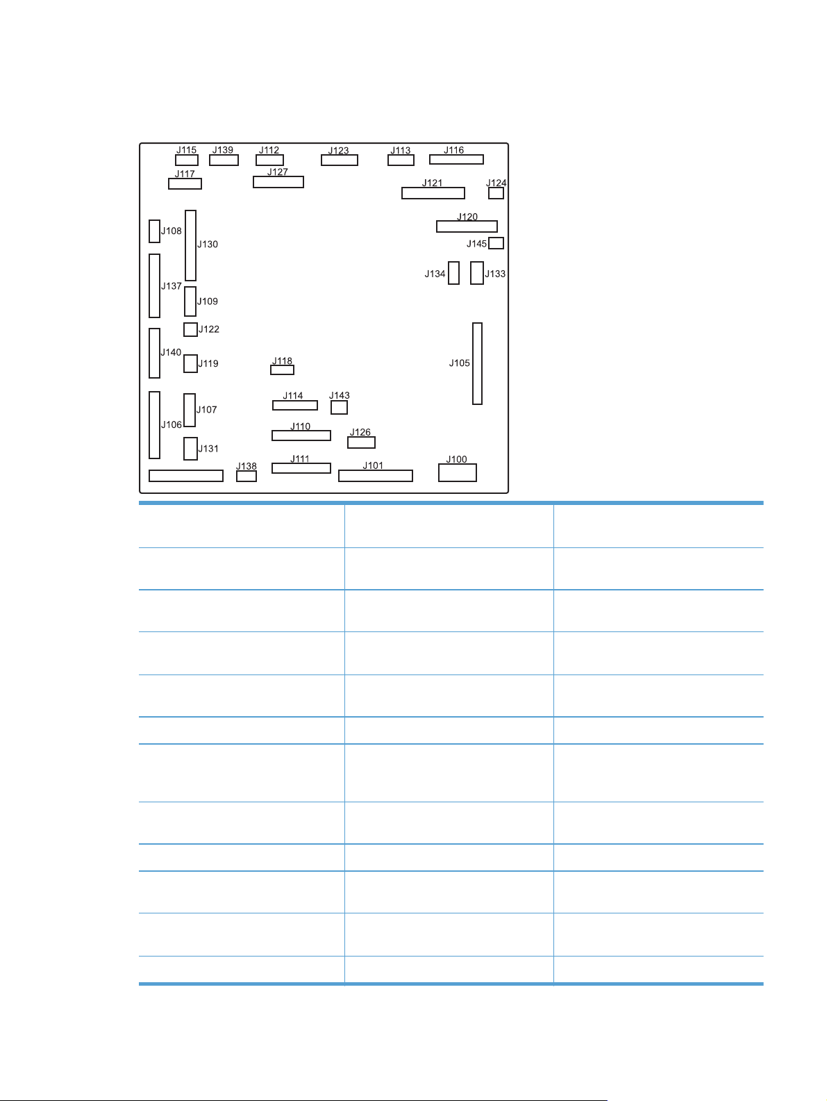
DC controller PCA
Figure 1-2 DC controller PCA
J100: 24 v from low-voltage power
supply (LVPS) and interlock
J101: LVPS J115: fuser sensors J127: pre-exposure LEDs (rear), SR17,
J105: interconnect board (ICB) J116: HVPS upper J130: registration density (RD) sensors
J106: 500-sheet feeder, developing
home position, laser motors
J107: duplex sensor, tray 1 solenoid,
paper present sensor
J108: environmental sensor J119: LVPS fan J134: not used
J109: duplex clutch, overhead
transparency (OHT) in, top-of-page
sensor
J110: YM laser J121: drum motor 3, drum position
J111: CK laser J122: OHT out J139: fuser sensors
J112: pre-exposure LEDs (front) J123: pressure release, bin full, fuser
J114: HVPS lower J126: memory tag connector
SL1
(front and rear)
J117: fuser motor J131: pickup motor
J118: 5 v interlock J133: not used
J120: drum motor 1 and drum motor 2 J137: toner collection unit (TCU) full,
TCU motor, toner level detection
J138: 24 v to HVPS lower
1,2,3
J140: lift motor, tray present, stack
delivery
surface
ENWW
J113: 24 v to high-voltage power
supply (HVPS) upper
J145 :not used
J124: 24 v to scanner J143: 24 v present from LVPS
Service approach
7

Parts removal order
Some procedures in this chapter include a list of assemblies that must be removed prior to beginning a
specific removal process. Remove the listed assemblies in the order that they appear in the list.
8 Chapter 1 Removal and replacement ENWW

Removal and replacement procedures
Customer self repair (CSR) components
NOTE: Your product might not appear exactly as the one shown in the photos in this chapter.
Although some photos do not show the ADF/scanner unit, the procedures in this chapter are
appropriate for this product.
Toner cartridges
CAUTION: If toner gets on your clothing, wipe it off with a dry cloth and wash clothing in cold
water.
Hot water sets toner into fabric
1. Open the front door. Make sure that the door is completely open.
Figure 1-3 Remove the toner cartridge (1 of 2)
.
ENWW
Removal and replacement procedures
9

2. Grasp the toner-cartridge handle and pull it out of the product to remove it.
CAUTION: Do not touch the green roller. Doing so can damage the cartridge. Do not expose
the cartridge to strong light. Cover the cartridge with a sheet of paper to protect it from light.
Reinstallation tip Align the toner cartridge with its slot and insert the toner cartridge until it
clicks into place.
Figure 1-4 Remove the toner cartridge (2 of 2)
10 Chapter 1 Removal and replacement ENWW

Duplex-reverse guide
1. Grasp the duplex-reverse guide and pull it away from the product to release it.
Figure 1-5 Remove the duplex-reverse guide (1 of 2)
2. Remove the guide.
Figure 1-6 Remove the duplex-reverse guide (2 of 2)
ENWW
Removal and replacement procedures
11

Toner-collection unit
NOTE: The toner-collection unit is designed for a single use. Do not try to empty the toner-collection
unit and reuse it. Doing so could cause toner to spill inside the product and result in reduced print
quality. For recycling information, see the product user guide.
1. Open the front door. Make sure that the door is completely open.
Figure 1-7 Remove the toner-collection unit (1 of 4)
2. Grasp the blue label at the top of the toner-collection unit and remove it from the product.
Reinstallation tip Insert the bottom of the replacement unit into the product first and then push
the top of the unit until it clicks into place. If the toner-collection unit is installed incorrectly, the front
door will not close completely.
Figure 1-8 Remove the toner-collection unit (2 of 4)
12 Chapter 1 Removal and replacement ENWW

3. To prevent toner spills, place the blue cap (callout 1) over the blue opening at the top of the unit
(callout 2).
Figure 1-9 Remove the toner-collection unit (3 of 4)
2
1
Figure 1-10 Remove the toner-collection unit (4 of 4)
ENWW
Removal and replacement procedures
13

Tray 2 and 3
NOTE: Use this procedure to remove the Tray 2 or optional Tray 3.
1. Pull the tray straight out of the product until it stops.
Figure 1-11 Remove Tray 2 and 3 (1 of 2)
2. Carefully lift up on the tray to release it, and then remove the tray.
Figure 1-12 Remove Tray 2 and 3 (2 of 2)
14 Chapter 1 Removal and replacement ENWW

Pickup roller and separation pad (Tray 1)
CAUTION: Skin oils on the roller or pad can cause paper pickup problems. Wash your hands
before handling the assembly.
1. Open Tray 1, release two tabs (callout 1), and then rotate the roller cover away from the product
to remove it.
TIP: Push down along the top edge of the cover to easily release the tabs.
Figure 1-13 Remove the pickup roller and separation pad (Tray 1) (1 of 3)
1
2. Release two tabs and rotate the roller body away from the product to remove it.
Figure 1-14 Remove the pickup roller and separation pad (Tray 1) (2 of 3)
ENWW
Removal and replacement procedures
15

3. Use a small flat blade screwdriver to release two tabs, and then remove the separation pad.
TIP: You might need to slightly depress the spring-loaded separation pad pedestal to remove the
separation pad.
Figure 1-15 Remove the pickup roller and separation pad (Tray 1) (3 of 3)
16 Chapter 1 Removal and replacement ENWW

Pickup roller (Tray 2)
CAUTION: Skin oils on the roller can cause paper pickup problems. Wash your hands before
handling the assembly.
1. Look up into the Tray 2 cavity (where the tray would be installed), and pull down to release the
blue roller-locking lever.
Reinstallation tip When the roller is reinstalled, rotate the roller shaft several times to make
sure that the shaft correctly engages the drive mechanism. You should hear a click when the shaft
engages the drive mechanism.
Figure 1-16 Remove the pickup roller (Tray 2) (1 of 4)
2. Pull the roller toward the front of the product to release the rear of the roller shaft.
Figure 1-17 Remove the pickup roller (Tray 2) (2 of 4)
ENWW
Removal and replacement procedures
17

3. Rotate the roller shaft down and away from the product, and then slide the roller toward the rear
of the product to release the front of the roller shaft.
Figure 1-18 Remove the pickup roller (Tray 2) (3 of 4)
4. Remove the pickup roller.
Reinstallation tip Make sure that the roller is orientated correctly when it is reinstalled (the
large white collar should be positioned toward the front of the product.
Figure 1-19 Remove the pickup roller (Tray 2) (4 of 4)
18 Chapter 1 Removal and replacement ENWW

Pickup and feed rollers (Tray 3)
CAUTION: Skin oils on the roller can cause paper pickup problems. Wash your hands before
handling the assembly.
1. Locate the Tray 3 pickup and feed rollers.
TIP: The feeder is shown front side up in this procedure for clarity. You do not have to separate
the product from the feeder to remove these rollers. Remove the tray, and then reach up into the
cavity to remove the rollers.
Figure 1-20 Remove the pickup and feed rollers (Tray 3) (1 of 2)
ENWW
Removal and replacement procedures
19

2. Release three tabs (callout 1), and then remove the rollers.
Reinstallation tip When you reinstall the rollers, make sure that the rollers snap into place.
Figure 1-21 Remove the pickup and feed rollers (Tray 3) (2 of 2)
1
20 Chapter 1 Removal and replacement ENWW

Separation roller (Tray 2)
CAUTION: Skin oils on the roller can cause paper pickup problems. Wash your hands before
handling the assembly.
NOTE: Remove the Tray 2 if not already removed for service. See Tray 2 and 3 on page 14.
Remove two screws (callout 1), and then remove the separation roller assembly (callout 2).
Figure 1-22 Remove the separation roller (Tray 2)
2
1
CAUTION: To install a self-tapping screw, first turn it counterclockwise to align it with the thread
pattern, and then carefully turn it clockwise to tighten. Do not overtighten. If a self-tapping screw-hole
becomes stripped, repair the screw-hole or replace the affected assembly.
ENWW
Removal and replacement procedures
21

Secondary transfer roller
CAUTION: Do not touch the spongy roller surface unless you are replacing the roller. Skin oils on the
roller can cause image quality problems.
1. Open the right-door assembly.
Figure 1-23 Remove the transfer roller (1 of 3)
2. Use the blue lever (callout 1) to lower the secondary transfer assembly.
Figure 1-24 Remove the transfer roller (2 of 3)
1
22 Chapter 1 Removal and replacement ENWW

3. Grasp the roller shaft collars, and lift the transfer roller off of the product.
Figure 1-25 Remove the transfer roller (3 of 3)
Reinstall the transfer roller
When you reinstall the transfer roller, make sure that the pins on the shaft collars (callout 1) align with
the holes in the mounting assembly.
Figure 1-26 Reinstall the transfer roller
1
ENWW
Removal and replacement procedures
23

Intermediate transfer belt (ITB)
CAUTION: Do not touch the black-plastic belt. Skin oils and fingerprints on the belt can cause print-
quality problems. Always place the ITB on a flat surface in a safe and protected location.
1. Open the right-door assembly.
Figure 1-27 Remove the intermediate transfer belt (1 of 4)
2. Use the blue lever (callout 1) to lower the secondary transfer assembly.
Figure 1-28 Remove the intermediate transfer belt (2 of 4)
1
24 Chapter 1 Removal and replacement ENWW

3. Grasp the small handles on the ITB and then pull the ITB out of the product until two large handles
expand along the left and right sides of the ITB.
Figure 1-29 Remove the intermediate transfer belt (3 of 4)
ENWW
Removal and replacement procedures
25

4. Grasp the large handles on the ITB and then pull the ITB straight out of the product to remove it.
CAUTION: The ITB is a sensitive component. Be careful when handling the ITB so that it is not
damaged. Always place the ITB in a safe and protected location.
Figure 1-30 Remove the intermediate transfer belt (4 of 4)
Reinstallation tip If you are installing a replacement ITB, make sure that you remove all of the
packing tape (callout 1) and the protective cover sheet (callout 2).
2
1
26 Chapter 1 Removal and replacement ENWW

Front-door assembly
1. Open the front door.
Figure 1-31 Remove the front-door assembly (1 of 2)
2. Remove two screws (callout 1), and then remove the front-door assembly.
NOTE: A small sheet-metal bracket on the left side of the door is not captive. Do not lose the
bracket when you remove the screw.
Figure 1-32 Remove the front-door assembly (2 of 2)
1
3. If you are installing a replacement front-door assembly, install the HP nametag and the
appropriate product model number tag on the assembly.
ENWW
Removal and replacement procedures
27

Document feeder pickup rollers
CAUTION: Skin oils deposited on the roller might cause print-quality problems. Wash your hands
before handling the assembly.
1. Open the jam-access cover.
Figure 1-33 Remove the document feeder pickup rollers (1 of 5)
2. Release one tab (callout 1).
Figure 1-34 Remove the document feeder pickup rollers (2 of 5)
1
28 Chapter 1 Removal and replacement ENWW

3. Rotate the shaft end of the roller assembly away from the document feeder (callout 1), and then
slide the gear end of the roller out of the document feeder (callout 2) to remove the upper-roller
assembly.
Figure 1-35 Remove the document feeder pickup rollers (3 of 5)
1
2
4. Release one tab (callout 1).
Figure 1-36 Remove the document feeder pickup rollers (4 of 5)
1
ENWW
Removal and replacement procedures
29

5. Rotate the shaft end of the roller assembly away from the document feeder (callout 1), and then
slide the gear end of the roller out of the document feeder (callout 2) to remove the lower-roller
assembly.
Figure 1-37 Remove the document feeder pickup rollers (5 of 5)
1
2
TIP: The roller assembly is keyed. When reinstalling the roller assembly, position the hex-shaped
fitting on the shaft toward the rear of the product.
30 Chapter 1 Removal and replacement ENWW

Document feeder separation pad
CAUTION: Skin oils deposited on the roller might cause print-quality problems. Wash your hands
before handling the assembly.
1. Open the jam-access cover.
Figure 1-38 Remove the document feeder separation pad (1 of 2)
2. Locate the separation pad at the end of the document feeder input tray, press down on the pad,
and then slide the pad toward the input tray to remove it from the assembly.
Figure 1-39 Remove the document feeder separation pad (2 of 2)
ENWW
Removal and replacement procedures
31

Control panel
Before proceeding, remove the following components:
Right-rear cover. See
●
Left cover. See
●
Rear-upper cover. See
●
Left-upper cover. See
●
Right-upper rear cover. See
●
Rear cover. See
●
Document feeder. See
●
Image scanner. See
●
Interconnect board (ICB). See
●
TIP: Removing the ICB makes it easier to connect the control panel FFC when the control panel is
reinstalled.
Remove the control panel
1. Disconnect one one FFC (callout 1).
Figure 1-40 Remove the control panel (1 of 6)
Right-rear cover on page 48.
Left cover on page 50.
Rear-upper cover on page 53.
Left-upper cover on page 54.
Right-upper rear cover on page 55.
Rear cover on page 56.
Document feeder on page 73.
Image scanner on page 77.
Interconnect board (ICB) on page 88.
1
32 Chapter 1 Removal and replacement ENWW

2. Feed the cable through the hole in the chassis (callout 1).
Reinstallation tip The FFC might be fastened to the chassis in several places with two-sided
adhesive tape. Make sure that you refasten the FFC to the chassis when the control panel is
reinstalled.
Figure 1-41 Remove the control panel (2 of 6)
1
3. Remove one screw (callout 1), and then remove the right-upper front cover (callout 2).
Figure 1-42 Remove the control panel (3 of 6)
2
1
ENWW
Removal and replacement procedures
33

4. Remove one screw.
Figure 1-43 Remove the control panel (4 of 6)
5. Carefully slide the control panel toward the right side of the product to release the left most hinge
pin.
Figure 1-44 Remove the control panel (5 of 6)
34 Chapter 1 Removal and replacement ENWW

6. Rotate the left side of the control panel up (callout 1) and away from the product to release the
right most hinge pin, and then slide the control panel to the left (callout 2) to remove it.
Figure 1-45 Remove the control panel (6 of 6)
2
1
ENWW
Removal and replacement procedures
35

USB PCA
Before proceeding, remove the following components:
Control panel. See
●
Right-rear cover. See
●
Left cover. See
●
Left-upper cover. See
●
Right-upper rear cover. See
●
Rear cover. See
●
Upper-right cover. See
●
Document feeder. See
●
Image scanner. See
●
Interconnect board (ICB). See
●
TIP: Removing the ICB makes it easier to connect the control panel FFC when the control panel is
reinstalled.
Remove the USB PCA
CAUTION: ESD sensitive component.
Control panel on page 32.
Right-rear cover on page 48.
Left cover on page 50.
Left-upper cover on page 54.
Right-upper rear cover on page 55.
Rear cover on page 56.
Upper-right cover on page 66.
Document feeder on page 73.
Image scanner on page 77.
Interconnect board (ICB) on page 88.
1. Disconnect one connector (callout 1).
Figure 1-46 Remove the USB PCA (1 of 3)
36 Chapter 1 Removal and replacement ENWW

2. Remove one screw (callout 1).
Figure 1-47 Remove the USB PCA (2 of 3)
3. Remove the PCA.
Figure 1-48 Remove the USB PCA (3 of 3)
ENWW
Removal and replacement procedures
37

Control panel friction mount
Before proceeding, remove the following components:
Control panel. See
●
USB PCA. See
●
Right-rear cover. See
●
Left cover. See
●
Left-upper cover. See
●
Right-upper rear cover. See
●
Rear cover. See
●
Upper-right cover. See
●
Document feeder. See
●
Image scanner. See
●
Remove the control panel friction mount
Use a small flat blade screw driver to carefully pry the friction mount straight up and off of the press fit
pin (callout 1).
CAUTION: The pin is easily broken. Be very careful when removing the friction mount assembly.
Control panel on page 32.
USB PCA on page 36.
Right-rear cover on page 48.
Left cover on page 50.
Left-upper cover on page 54.
Right-upper rear cover on page 55.
Rear cover on page 56.
Upper-right cover on page 66.
Document feeder on page 73.
Image scanner on page 77.
Figure 1-49 Remove the control panel friction mount
1
38 Chapter 1 Removal and replacement ENWW

Right door (optional paper feeder)
1. Open the right door.
Figure 1-50 Remove the right door; optional paper feeder (1 of 3)
2. Release one tab (callout 1), and then slide the stopper toward the right side of the product to
remove it.
Figure 1-51 Remove the right door; optional paper feeder (2 of 3)
1
ENWW
Removal and replacement procedures
39

3. Support the door, and then release the door-retainer arm at the bottom of the door. Raise the door
to release the lower hinge pin, and then remove the door.
Figure 1-52 Remove the right door; optional paper feeder (3 of 3)
40 Chapter 1 Removal and replacement ENWW

External panels, covers, and doors
Identification and location
NOTE: Your product might not appear exactly as the one shown in the photos in this chapter.
Although some photos do not show the ADF/scanner unit, the procedures in this chapter are
appropriate for the product.
Figure 1-53 Product base, external panels, covers, doors; identification and location
1
7
2
15
14
3
4
13
5
12
6
11
10
Table 1-2 Product base, external panels, covers, doors; identification and location
Item Description
1 Rear-top cover (see
2 Right-top cover (see
3 Right-rear cover (see
4 Right-door assembly (see
Rear-top cover on page 71)
Right-top cover on page 64)
Right-rear cover on page 48)
Right-door assembly on page 44)
8
9
ENWW
5 Right-front cover (see
6 Upper-right cover (see
7 Delivery cover (see
8 Left-upper cover (see
9 Left cover (see
10 Rear cover (see
11 Tray (see
12 Front-door assembly (see
13 Front-upper cover (see
14 Front-top cover (see
Tray 2 and 3 on page 14)
Right-front cover on page 58)
Upper-right cover on page 66)
Delivery cover on page 62)
Left-upper cover on page 54)
Left cover on page 50)
Rear cover on page 56)
Front-upper cover on page 42)
Front-top cover on page 69)
Front-door assembly on page 27)
Removal and replacement procedures
41

Front-upper cover
Remove the front-upper cover
1. Open the right door and the front door.
Figure 1-54 Remove the front-upper cover (1 of 4)
2. Remove one screw (callout 1).
Figure 1-55 Remove the front-upper cover (2 of 4)
42 Chapter 1 Removal and replacement ENWW

3. Remove one screw (callout 1).
Figure 1-56 Remove the front-upper cover (3 of 4)
4. Lift the cover up to release it, and then remove the cover.
NOTE: The cover might be difficult to remove. It might require some flexing to release it.
Figure 1-57 Remove the front-upper cover (4 of 4)
ENWW
Removal and replacement procedures
43

Right-door assembly
1. Open the right-door assembly.
Figure 1-58 Remove the right-door assembly (1 of 8)
2. Close the secondary transfer assembly.
Figure 1-59 Remove the right-door assembly (2 of 8)
44 Chapter 1 Removal and replacement ENWW

3. Remove three screws (callout 1).
Figure 1-60 Remove the right-door assembly (3 of 8)
1
4. Carefully release one link arm.
Figure 1-61 Remove the right-door assembly (4 of 8)
ENWW
Removal and replacement procedures
45

5. Remove one screw (callout 1), and then remove the cover (callout 2).
Figure 1-62 Remove the right-door assembly (5 of 8)
3
2
6. Disconnect two connectors (callout 1), and then release the wire harness from the guide
(callout 2).
TIP: It is easier to disconnect the lower connector if you first remove the wire harnesses from the
guide.
Figure 1-63 Remove the right-door assembly (6 of 8)
4
5
46 Chapter 1 Removal and replacement ENWW

7. Remove two screws (callout 1).
Figure 1-64 Remove the right-door assembly (7 of 8)
8. Remove the right-door assembly.
Figure 1-65 Remove the right-door assembly (8 of 8)
7
ENWW
Removal and replacement procedures
47

Right-rear cover
1. Open the right-door assembly.
Figure 1-66 Remove the right-rear cover (1 of 3)
2. Remove two screws (callout 1) and release one tab (callout 2).
Figure 1-67 Remove the right-rear cover (2 of 3)
2
1
48 Chapter 1 Removal and replacement ENWW

3. Rotate the bottom of the cover away from the product, and then remove the cover.
Figure 1-68 Remove the right-rear cover (3 of 3)
ENWW
Removal and replacement procedures
49

Left cover
1. Remove four screws (callout 1).
2. Release the rear edge of the cover, and slightly separate the cover from the product.
Figure 1-69 Remove the left cover (1 of 5)
1
Figure 1-70 Remove the left cover (2 of 5)
50 Chapter 1 Removal and replacement ENWW

3. The figure below shows the cover removed so that you can see the mounting tab locations.
Before proceeding, note the location of the mounting tabs.
CAUTION: One tab (callout 2) is easily damaged when removing the cover. Be careful when
removing the cover.
Figure 1-71 Remove the left cover (3 of 5)
2
4. Use your thumb to press in on the lower-front portion of the cover (callout 1 near the dashed circle
in the figure below), and then slightly slide the cover away (callout 2) from the front door to
release one tab.
CAUTION: You must flex the cover enough to release the front edge of the cover, but do not
damage the tab at the bottom-front edge of the cover. See callout 2 in
cover (3 of 5) on page 51.
Figure 1-72 Remove the left cover (4 of 5)
Figure 1-71 Remove the left
2
1
ENWW
Removal and replacement procedures
51

5. Slide the cover toward the rear of the product and rotate it away from the product and then
remove the cover.
Figure 1-73 Remove the left cover (5 of 5)
52 Chapter 1 Removal and replacement ENWW

Rear-upper cover
1. Remove two screws (callout 1).
Figure 1-74 Remove the rear-upper cover (1 of 2)
2. Rotate the cover away from the product to remove it. See example below under Remove the right-
upper cover.
1
Figure 1-75 Remove the rear-upper cover (2 of 2)
ENWW
Removal and replacement procedures
53

Left-upper cover
Before proceeding, remove the following components:
Rear-upper cover. See
●
Remove the left-upper cover
Release one tab and remove the cover.
Figure 1-76 Remove the left-upper cover
Rear-upper cover on page 53.
54 Chapter 1 Removal and replacement ENWW

Right-upper rear cover
Before proceeding, remove the following components:
Rear-upper cover. See
●
Remove the right-upper cover
Rotate the cover away from the product (callout 1) to release it, and then slide it toward the rear of the
product (callout 2) to remove it.
Figure 1-77 Remove the right-upper cover
2
Rear-upper cover on page 53.
1
ENWW
Removal and replacement procedures
55

Rear cover
Before proceeding, remove the following components:
Right-rear cover. See
●
Left cover. See
●
Rear-upper cover. See
●
Remove the rear cover
1. Remove eight screws (callout 1).
Figure 1-78 Remove the rear cover (1 of 2)
Right-rear cover on page 48.
Left cover on page 50.
Rear-upper cover on page 53.
1
56 Chapter 1 Removal and replacement ENWW

2. Slide the cover toward the fan side of the product, and then remove the rear cover.
Figure 1-79 Remove the rear cover (2 of 2)
ENWW
Removal and replacement procedures
57

Right-front cover
Before proceeding, remove the following components:
Front-upper cover. See
●
Remove the right-front cover
NOTE: Be careful. When removing the cover, do not dislodge the power button. If the button is
dislodged, see
1. Remove one screw (callout 1).
Figure 1-80 Remove the right-front cover (1 of 5)
Reinstall the power button on page 61 to reinstall it.
Front-upper cover on page 42.
1
58 Chapter 1 Removal and replacement ENWW

2. Remove two screws (callout 2).
Figure 1-81 Remove the right-front cover (2 of 5)
2
3. Before you proceed, take note of the tab locations at the bottom of the cover.
Figure 1-82 Remove the right-front cover (3 of 5)
ENWW
Removal and replacement procedures
59

4. Pull down on the cover to release three tabs (callout 3).
TIP: It might be easier if you position the product at the edge of the work surface so that there is
a space for the cover to slide downward. Or, you might try inserting a small flat blade screwdriver
behind the cover, and carefully pry the cover away from the product as you pull down on the
cover to release the tabs.
Figure 1-83 Remove the right-front cover (4 of 5)
3
5. Rotate the bottom of the cover away from the product, and then pull down on the cover to remove
it.
Figure 1-84 Remove the right-front cover (5 of 5)
60 Chapter 1 Removal and replacement ENWW

Reinstall the power button
Snap the power button into the holders on the cover. Make sure that the spring is correctly installed.
Figure 1-85 Reinstall the power button
ENWW
Removal and replacement procedures
61

Delivery cover
Before proceeding, remove the following components:
Front-upper cover. See
●
Rear-upper cover. See
●
Left-upper cover. See
●
Upper-right cover. See
●
Document feeder. See
●
Image scanner. See
●
Remove the delivery cover
1. Remove three screws.
Figure 1-86 Remove the delivery cover (1 of 3)
Front-upper cover on page 42.
Rear-upper cover on page 53.
Left-upper cover on page 54.
Upper-right cover on page 66.
Document feeder on page 73.
Image scanner on page 77.
62 Chapter 1 Removal and replacement ENWW

2. Lift up (callout 1) and slide the delivery cover (callout 2).
Figure 1-87 Remove the delivery cover (2 of 3)
2
1
3. Remove the delivery cover.
Figure 1-88 Remove the delivery cover (3 of 3)
ENWW
Removal and replacement procedures
63

Right-top cover
Before proceeding, remove the following components:
Rear-upper cover. See
●
Left-upper cover. See
●
Document feeder. See
●
Image scanner. See
●
Remove the right-top cover
1. Remove three screws.
Figure 1-89 Remove the right-top cover (1 of 2)
Rear-upper cover on page 53.
Left-upper cover on page 54.
Document feeder on page 73.
Image scanner on page 77.
64 Chapter 1 Removal and replacement ENWW

2. Disconnect one connector (callout 1), remove the wire harness from its retainer (callout 2), and
remove the cover.
Figure 1-90 Remove the right-top cover (2 of 2)
21
ENWW
Removal and replacement procedures
65

Upper-right cover
Before proceeding, remove the following components:
Control panel. See
●
USB PCA. See
●
Right-rear cover. See
●
Left cover. See
●
Left-upper cover. See
●
Right-upper rear cover. See
●
Rear cover. See
●
Document feeder. See
●
Image scanner. See
●
Remove the upper-right cover
1. Remove one screw.
Figure 1-91 Remove the upper-right cover (1 of 5)
USB PCA on page 36.
Left cover on page 50.
Rear cover on page 56.
Control panel on page 32.
Right-rear cover on page 48.
Left-upper cover on page 54.
Right-upper rear cover on page 55.
Document feeder on page 73.
Image scanner on page 77.
66 Chapter 1 Removal and replacement ENWW

2. Release the USB cable from the retainers (callout 1).
Figure 1-92 Remove the upper-right cover (2 of 5)
1
3. Remove two screws.
Figure 1-93 Remove the upper-right cover (3 of 5)
ENWW
Removal and replacement procedures
67

4. Release one tab.
Figure 1-94 Remove the upper-right cover (4 of 5)
5. Carefully lift the upper-right cover straight up to remove it.
Figure 1-95 Remove the upper-right cover (5 of 5)
68 Chapter 1 Removal and replacement ENWW

Front-top cover
Before proceeding, remove the following components:
Rear-upper cover. See
●
Right-rear cover. See
●
Left cover. See
●
Left-upper cover. See
●
Right-upper rear cover. See
●
Document feeder. See
●
Image scanner. See
●
Wireless PCA. See
●
Remove the front-top cover
1. Remove one screw (callout 1).
Figure 1-96 Remove the front-top cover (1 of 2)
Left cover on page 50.
Rear-upper cover on page 53.
Right-rear cover on page 48.
Left-upper cover on page 54.
Right-upper rear cover on page 55.
Document feeder on page 73.
Image scanner on page 77.
Wireless PCA on page 87.
1
ENWW
Removal and replacement procedures
69

2. Slide the cover toward the left side of the product to release it, and then remove the cover.
Figure 1-97 Remove the front-top cover (2 of 2)
70 Chapter 1 Removal and replacement ENWW

Rear-top cover
Before proceeding, remove the following components:
Control panel. See
●
USB PCA. See
●
Control panel friction mount. See
●
Rear-upper cover. See
●
Left-upper cover. See
●
Right-upper rear cover. See
●
Rear cover. See
●
Delivery cover. See
●
Front-top cover. See
●
Document feeder. See
●
Image scanner. See
●
Wireless PCA. See
●
Upper-right cover. See
●
Interconnect board (ICB). See
●
Control panel on page 32.
USB PCA on page 36.
Left-upper cover on page 54.
Rear cover on page 56.
Delivery cover on page 62.
Front-top cover on page 69.
Image scanner on page 77.
Wireless PCA on page 87.
Control panel friction mount on page 38.
Rear-upper cover on page 53.
Right-upper rear cover on page 55.
Document feeder on page 73.
Upper-right cover on page 66.
Interconnect board (ICB) on page 88.
TIP: Removing the ICB makes it easier to connect the control panel FFC when the control panel is
reinstalled.
ENWW
Removal and replacement procedures
71

Remove the rear-top cover
Remove three screws, and then remove the cover.
Figure 1-98 Remove the rear-top cover
72 Chapter 1 Removal and replacement ENWW

Document feeder and scanner
Document feeder
Before proceeding, remove the following:
Right-rear cover. See
●
Left cover. See
●
Rear-upper cover. See
●
Right-upper rear cover. See
●
NOTE: After removing the document feeder assembly, place it on a clean, dry, and smooth surface.
1. Disconnect two connectors (callout 1) and one FFC (callout 2).
Figure 1-99 Remove the document feeder assembly (1 of 4)
Right-rear cover on page 48.
Left cover on page 50.
Rear-upper cover on page 53.
Right-upper rear cover on page 55.
1
2
ENWW
Removal and replacement procedures
73

2. Carefully feed the wire harnesses up through hole in the chassis (callout 1), and then feed the FFC
through the hole in the chassis (callout 2) and through the ferrite (callout 3).
TIP: When you reinstall the document feeder, it might be easier to remove the ferrite from the
product, pass the FFC though it, and then reinstall the ferrite in the product with two-sided
adhesive tape.
Figure 1-100 Remove the document feeder assembly (2 of 4)
3
1
3. Open the document feeder, and then lift it straight up until it stops.
Figure 1-101 Remove the document feeder assembly (3 of 4)
2
74 Chapter 1 Removal and replacement ENWW

4. Use a small flat blade screw driver to release two tabs (callout 1) on the hinges, and then pull the
document feeder straight up and off (callout 2) of the product to remove it.
TIP: Push the screw drive down into the hinge wells to release the tabs.
Figure 1-102 Remove the document feeder assembly (4 of 4)
2
1
ENWW
Removal and replacement procedures
75

Reinstall the document feeder
Calibrate a replacement document feeder assembly
1. On the control-panel Home screen, touch the Setup
2. Touch the System setup menu.
3. Touch the Print Quality menu.
4. Touch the Color Calibration item.
5. Touch the Calibrate now option.
6. Follow the instructions on the control-panel display.
Button.
76 Chapter 1 Removal and replacement ENWW

Image scanner
Before proceeding, remove the following components:
Right-rear cover. See
●
Left cover. See
●
Rear-upper cover. See
●
Left-upper cover. See
●
Right-upper rear cover. See
●
Document feeder. See
●
Remove the image scanner
1. Disconnect one FFC (callout 1), and then carefully feed it through the hole in the chassis
(callout 2).
Figure 1-103 Remove the image scanner (1 of 5)
Right-rear cover on page 48.
Left cover on page 50.
Rear-upper cover on page 53.
Left-upper cover on page 54.
Right-upper rear cover on page 55.
Document feeder on page 73.
1
2
ENWW
Removal and replacement procedures
77

2. Remove two screws on the back side of the scanner.
Figure 1-104 Remove the image scanner (2 of 5)
3. Remove one screw on the right side of the scanner.
Figure 1-105 Remove the image scanner (3 of 5)
78 Chapter 1 Removal and replacement ENWW
 Loading...