

Page 1

Programmer's Guide
HP
Optical Spectrum
Analyzers
71450B/1B/2B
Page 2
HP Part No. 70950-90050
Edition 1
Printed in USA June 1995
1400 Fountaingrove Parkway,
Santa Rosa, CA
95403-1799, USA
Notice.
The information contained in this document is subject to change
without notice. Hewlett-Packard makes no warranty of any kind with regard
ackard
this
of
of
shall
material,
this
to
merchantability
be liable
not
damages
for
connection
in
including
tness
and
contained
errors
with
but
for
the
limited
not
particular
a
herein
furnishing,
the
,
to
purpose
incidental
for
or
performance
implied
Hewlett-P
.
warranties
consequential
or
use
or
,
material.
.
.S
U
the
Restricted
Rights
Government
Rights
the
of
252.227-7013
Commercial
agencies
other
Legend.
subject
is
echnical
T
in
DOD
for
Computer
.
Use
restrictions
to
Data
agencies
Software
duplication,
,
set
as
and Computer
subparagraphs
and
,
Restricted
or
forth
Software
Rights
disclosure
in
clause
by
subparagraph
at
and
FAR
at
(c)
clause
(c) (1)
(1)
(c)
ARS
DF
the
of
(2)
52.227-19
(ii)
for
c
Copyright Hewlett-P
ackard Company 1995
All Rights Reserved. Reproduction, adaptation, or translation without prior
written permission is prohibited, except as allowed under the copyright laws.
Page 3
Start
here
Remote operation with HP 71450B/1B/2B
This introduction provides you with a quick overview of some basic concepts
you will need to successfully program the HP 71450B/1B/2B optical spectrum
analyzer (OSA). The OSA oers extensive remote programming capability
which includes the following features:
Setting measurement ranges
Querying values to the computer
Creating new functions
arrays
trace
Creating
Processing
ctivating new
A
Allowing
Placing
Monitoring
Finish
1.
programming
Read
2.
A.
OS
user-dened
information with
functions with
front-panel control
graphics and
instrument
introduction
reading
this
control
Chapter 1,
\Learning
variables
text on
operation
are covered
and
math and
move commands
front-panel keys
during remote
screen
the
returning
by
learn
and
this
in
the
Basics"
to
operation
a
what
manual.
connect
status
areas
the
to
byte
basic
of
computer
the computer
the
to
module
A
OS
The
described
as
Installation
in
and
should
HP
the
erication
V
arrive
installed
71450B/1B/2B
Manual
in
Optical
.
display
the
Spectrum
mainframe
Analyzer
3. Read the remaining chapters to learn specic details about remote
programming.
4. Chapter 7, \Language Reference" documents each OSA command in
alphabetical order.
Chapter
5.
programming
softkey
and
ables
8, \T
OSA.
the
cross-references
Charts"
contains
Functional
also
are
groups
provided.
additional
programming
of
information
related
commands
to
with
iii
Page 4
Computer Model in
Examples
The programming examples provided in this book used an HP 9000 Series 300
technical computer and the HP-BASIC language. However, you can use other
computers and languages with OSA commands and query data over HP-IB.
As an example, you could use an HP Vectra PC compatible computer.Simply
install an HP 82335A HP-IB Interface and Command Library card in the PC
and use a compatible language such as Microsoft QuickC.
Local and Remote
Control Indicators
Designing
Programs
Default HP-IB
Addresses
Whenever the analyzer is addressed via HP-IB, the
4
MENU
5
and
4
USER
5
keys
are disabled. The front-panel LEDs indicate the following:
RMT indicates remote HP-IB control.
.
HP-IB
LSN
TLK
SRQ
programs
A
OS
Except
.
keys
manual
Note
1.
Identify
2.
the
to
Charts
Incorporate
3.
indicates
indicates
indicates
for
operation.
order
the
which
functional
."
information
information
OS
the
composed
are
timing
design
o
T
keystrokes
of
commands
group
commands
the
received
sent
requesting
is
A
of
considerations
program,
a
correspond
tables
into
via
HP-IB
via
computer
commands
remote
,
perform
to
used
commands
of
output
to computer
correspond
that
operation
the
use
an OS
the
with
in
statements
.
attention.
front-panel
to
is very
similar
following procedure:
measurement.
A
Refer
8,
used.
ables
\T
keystrokes
Chapter
.
to
and
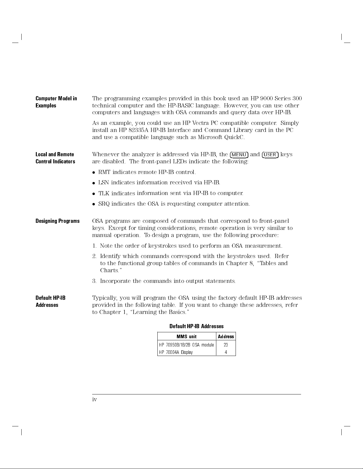
Typically, you will program the OSA using the factory default HP-IB addresses
provided in the following table. If you want to change these addresses,refer
to Chapter 1, \Learning the Basics."
iv
Addresses
HP-IB
Default
unit
MMS
Address
HP 70950B/1B/2B OSA module 23
HP 70004A Displa
y
4
Page 5
CAUTION
N
I
N
R
A
W
Safety Notes
The following safety notes are used throughout this manual. Familiarize
yourself with each of the notes and its meaning before operating this
instrument.
The
caution
note denotes a hazard. It calls attention to a procedure which,
if not correctly performed or adhered to, could result in damage to or
destruction of the instrument. Do not proceed beyond a
caution
note until
the indicated conditions are fully understood and met.
procedure
attention
calls
and
It
adhered
or
warning
a
met.
product
The
,
to
note
marked
is
manual.
the
in
hazard.
denotes
not
.
are
Do
The
for
note
correctly
proceed
not
understood
fully
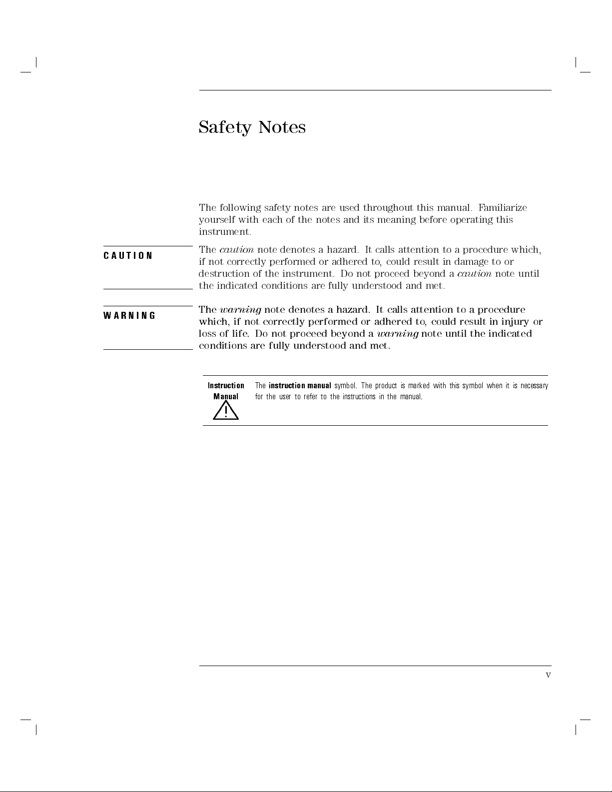
instruction
to
user
the
warning
G
The
which,
of
loss
if
life
conditions
Instruction
Manual
a
performed
beyond
symbol.
manual
the
to
refer
instructions
to a
could result
until the
this symbol
with
in injury
indicated
is
it
when
or
necessary
L
v
Page 6

General Safety Considerations
WARNING
IN
RN
WA
N
O
I
T
U
A
C
Before this instrument is switched on
, make sure it has been properly
grounded through the protective conductor of the ac power cable to a
socket outlet provided with protective earth contact.
Any interruption of the protective (grounding) conductor, inside or
outside the instrument, or disconnection of the protective earth terminal
can result in personal injury.
of
the
damage
cause
by
only
circuitry
to
can,
require operation
performed
be
primary
its
sure
.
source
voltage
plugged
could
in.
power
cause
the
make
power
ac
correct
is
which
G
There
personal injury
are
.Be
points
many
Any adjustments
protective covers
instrument
trained
Before
been
has
ailure
F
instrument
the
with
service
instrument
this
adapted
set
to
personnel.
the
when
in
extremely careful.
or service
the
to
power
ac
the
procedures that
switched
is
voltage
input
power
ac
removed should
on,
the
of
to
cable
instrument
the
contacted,
if
vi
Page 7

Certication
Hewlett-Packard Company certies that this product met its published
specications at the time of shipment from the factory.Hewlett-Packard
further certies that its calibration measurements are traceable to the United
States National Institute of Standards and Technology, to the extent allowed
by the Institute's calibration facility, and to the calibration facilities of other
International Standards Organization members.
Regulatory Information
The specications and characteristics chapter contains regulatory information.
vii
Page 8
Warranty
This Hewlett-Packard instrument product is warranted against defects in
material and workmanship for a period of one year from date of shipment.
During the warranty period, Hewlett-Packard Company will, at its option,
either repair or replace products which prove to be defective.
For warranty service or repair, this product must be returned to a service
facility designated by Hewlett-Packard. Buyer shall prepay shipping charges
to Hewlett-Packard and Hewlett-Packard shall pay shipping charges to return
duties
product
the
and taxes
.
Buyer
to
for products
However
,
returned to
Buyer
shall
Hewlett-Packard
pay
shipping
all
from
charges
another
,
country
.
,
Hewlett-Packard
Hewlett-P
instructions
does
rmware
Limit
The
or
ackard
when
warrant
not
be
will
of
tion
a
foregoing
inadequate
interfacing,
environmental
maintenance
or
NO
OTHER
W
warrants that
for use
with an
properly installed
the
that
uninterrupted
arranty
W
warranty
maintenance
unauthorized
specications
.
ARRANTY
its software
instrument
operation
error-free
or
not
shall
Buyer
by
modication
for
EXPRESSED
IS
on that
the
of
to
apply
Buyer-supplied
,
or
product,
the
OR
and rmware
execute
will
instrument.
instrument,
.
operation
,
improper
or
resulting
defects
misuse
IMPLIED
designated
programming
its
Hewlett-P
software
or
software
site
HEWLETT-P
.
by
ackard
or
,
improper
from
or
outside
preparation
A
of
CKARD
SPECIFICALLY DISCLAIMS THE IMPLIED WARRANTIES OF
MERCHANTABILITY AND FITNESS FOR A PARTICULAR PURPOSE.
Exclusive Remedies
THE REMEDIES PROVIDED HEREIN ARE BUYER'S SOLE AND EXCLUSIVE
ANY
HEWLETT-P
REMEDIES
DIRECT
AMA
D
.
INDIRECT
,
,
GES
WHETHER
LEGAL THEORY
,
.
CKARD
A
SPECIAL,
ASED
B
SHALL
INCIDENT
CONTRACT
ON
BE LIABLE
NOT
OR CONSEQUENTIAL
AL,
TORT
,
FOR
OTHER
ANY
OR
,
the
viii
Page 9

Assistance
Product maintenance agreements and other customer assistance agreements
are available for Hewlett-Packard products.
For any assistance, contact your nearest Hewlett-Packard Sales and Service
Oce.
ix
Page 10
Typesetting Conventions
4
Front-Panel Key
NNNNNNNNNNNNNNNNNNNNNNN
Softkey
Screen Text
5
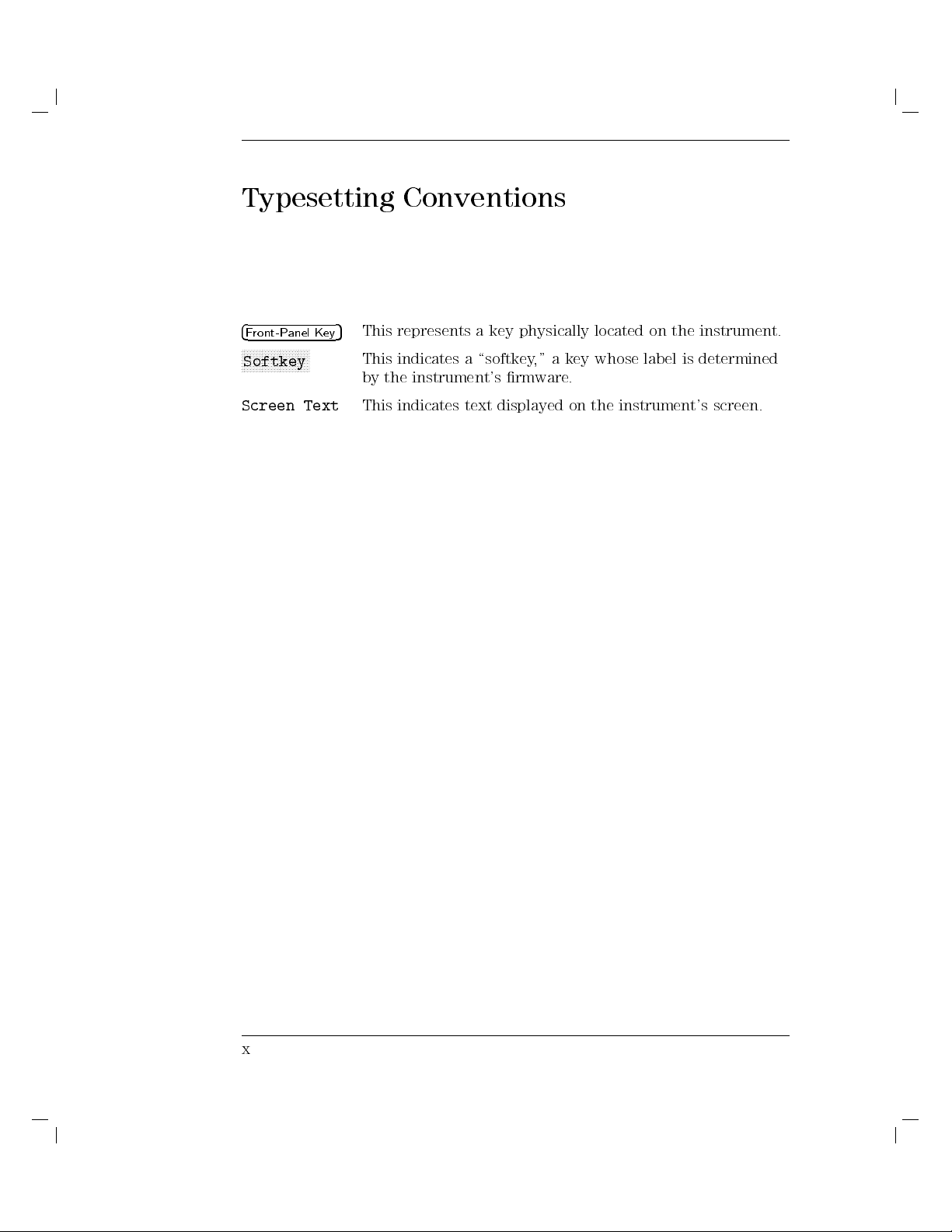
This represents a key physically located on the instrument.
This indicates a \softkey," a key whose label is determined
by the instrument's rmware.
This indicates text displayed on the instrument's screen.
x
Page 11
Contents
1. Learning the Basics
Preparing the OSA . . . . . . . . . . . . . . . . .
To prepare the OSA . . . . . . . . . . . . . . . .
Tochange the HP-IB address using switches . . . . .
Tochange the HP-IB address from the front panel . . .
Beginning Your Program . . . . . . . . . . . . . . .
To initialize the bus and the OSA . . . . . . . . . .
Sending Commands
commands
send
o
T
Returning
o
T
Using
o
T
Using
trolling
Con
tering
En
o
T
trolling
Con
Making
Data
v
a
query
Commands
command
a
use
V
MO
the
Program
Data
fron
w
allo
Adv
anced
adv
. .
the
to
alue
.
Argumen
as
argumen
Command
Timing
the
from
t-panel
anced
measurements
.
. .
OSA
the
to
Computer
. .
.
.
.
ts
t
.
.
.
anel
P
t
ron
F
try
en
data
Measuremen
.
.
.
. .
.
.
.
. .
.
.
.
.
.
.
.
.
.
.
.
.
.
.
.
Programs
t
er
ov
.
.
.
. .
. .
.
.
.
.
. .
.
.
. .
.
.
.
.
.
.
.
.
.
.
.
.
.
.
HP-IB
.
. .
. .
.
.
.
.
.
.
.
.
. .
.
.
.
.
.
.
.
.
. .
. .
.
.
.
.
.
.
.
.
1-4
1-7
1-8
1-9
1-10
1-10
1-11
.
.
.
1-13
.
.
. .
.
.
.
.
.
.
.
.
.
.
.
.
.
.
.
.
.
.
1-14
1-16
.
1-17
.
1-17
.
1-18
.
1-19
.
1-21
.
1-21
.
1-22
.
1-22
.
Traces
2.
Using
Dening
o
T
ariables
V
V
create
and
ariables
user-dened
a
. .
. .
. .
. .
.
.
.
.
.
.
. .
.
.
.
ariable
v
.
To erase a user-dened variable . . . . . . . . . . .
Dening Traces . . . . . . . . . . . . . . . . . . .
To create a user-dened trace . . . . . . . . . . . .
To erase a user-dened trace . . . . . . . . . . . .
Using Amplitude Data . . . . . . . . . . . . . . . .
.
.
.
.
.
.
the amplitude
select
o
T
measuremen
ert
v
con
o
T
To return w
Formatting T
avelength and p osition v
race-Data Output
Using Math and Mo
Trace Math Rule 1
Trace Math Rule 2
Trace Math Rule 3
units
t
ve Commands .
. . . . . . . . . . . . . . . .
. . . . . . . . . .
. . . . . . . . . . . . .
.
and
parameter
units
alues .
. . . . . . . . . . . .
. . . . . . . . . .
. . . . .
. . . . . .
2-4
.
.
.
.
. .
. .
2-5
2-5
2-6
2-7
2-7
2-8
2-9
.
. .
.
.
2-9
.
.
. .
.
.
2-9
2-10
2-15
2-16
2-17
. . .
2-17
Contents-1
Page 12
Trace Math Rule 4 . . . . . . . . . . . . . . . .
3. Controlling Memory
Saving and Recalling Items . . . . . . . . . . . . . .
To select user memory . . . . . . . . . . . . . . .
To catalog memory . . . . . . . . . . . . . . . .
Tosave a le . . . . . . . . . . . . . . . . . . .
To recall a le . . . . . . . . . . . . . . . . . .
Erasing Memory . . . . . . . . . . . . . . . . . .
To erase les . . . . . . . . . . . . . . . . . . .
To erase all memory except correction factors and
serial-number . . . . . . . . . . . . . . . . .
.
.
.
.
.
.
. .
y
. .
.
.
of in
.
. .
.
.
. .
.
.
.
.
ternal
memory
functions .
.
.
.
.
.
.
oerase
T
Protecting
protect
o
T
o
T
o
T
Memory
free
reduce
reeing
F
memory
all
Memory
les
greatest
the
the
from
.
size
for
. .
.
erasure .
. .
.
amount
user-dened
of
securit
. .
2-19
3-4
3-6
3-6
3-6
3-6
3-7
3-9
3-9
3-9
.
.
.
.
.
3-10
.
.
.
.
.
3-10
.
.
.
.
.
3-12
.
.
.
.
.
3-13
.
.
.
.
3-13
.
.
.
.
.
Monitoring
4.
Monitoring
terrupt
In
System
System
Pro
Analyzer Status-Byte
Service-Request Mask
Service-Request
Monitoring
Requests
Debugging Programs . . . . . . . . . . . . . . . . .
To debug a program . . . . . . . . . . . . . . . .
5. Creating Graphics
Clearing the Display.. . . . . . . . . . . . . . . .
the
clear
o
T
create
o
Graphics
a
Creating
T
Drawing Grids
wing Graphics Items
Dra
use a graphics item .
To
To delete a
Displaying T
To displaytext . . . . . . . . . . . . . . . . . .
Contents-2
Operation
.
.
.
.
.
.
.
cess
Examples
System
.
displa
wing
dra
Op
.
y
.
eration
.
.
Op
. .
.
. .
.
.
. .
.
.
Register
.
eration
. .
.
. .
.
.
.
.
.
.
.
.
.
.
.
.
.
.
.
. .
.
.
.
.
Without Using
. .
. .
.
.
.
.
.
.
.
.
.
.
.
.
.
.
.
.
.
.
.
.
.
.
.
. .
.
.
.
.
.
.
.
.
.
.
.
.
. . . . . . . . . . . . . . . . . . .
. . . . . . . . . . . . . . .
. . . . . . . . . . . . . .
graphics item .
ext .
. . . . . . . . . . . . . . . . . .
. . . . . . . . . . . . .
.
.
.
.
.
.
.
.
.
.
.
.
.
.
.
Service
.
.
.
. .
.
.
.
.
. .
.
.
.
.
.
.
.
.
. .
.
4-4
.
4-5
.
4-5
.
4-6
.
4-7
.
4-11
.
4-12
4-12
5-4
5-4
.
5-5
5-9
.
5-10
5-11
5-15
5-15
5-16
5-19
Page 13
To erase text . . . . . . . . . . . . . . . . . . .
Displaying Variables...... ...... ..... .. 5-20
To displayavariable . . . . . . . . . . . . . . . .
To erase displayed variables . . . . . . . . . . . . .
Changing the Scale . . . . . . . . . . . . . . . . .
Using Graphics Windows . . . . . . . . . . . . . . .
To reduce the displayarea . . . . . . . . . . . . .
To create a graphics window . . . . . . . . . . . .
To place a trace in a window . . . . . . . . . . . .
6. Creating Downloadable Programs
Creating a Downloadable Program . . . . . . . . . . .
.
.
.
.
.
.
.
.
.
.
.
.
.
function
ostore
T
o
T
Creating
Branc
o
T
o
T
o
T
Executing
o
T
o
T
o
T
Building
To
To
Avoiding
Controlling Instruments Over HP-IB . . . . . . . . . .
Tocontrol instruments over HP-IB . . . . . . . . .
a
conrm
hing,
use
use
ab
assign
execute
execute
assign
build in
a function
Activ
an
oping,
Lo
conditional
a
oping
lo
a
ops
lo
ort
User-Dened
function
a
function
a
function
a
USER
Illegal Recursion
Men
function
a
teractiv
and
.
is stored
User-Dened
e
Interrupting
and
branch
construct
user-dened functions
unctions
F
the
to
via
via
.
.
us
the
to
us
men
e
Function
. .
. .
USER
computer
t-panel
fron
.
.
.
4
USER
.
.
.
.
.
. .
.
.
.
.
5
.
.
.
.
.
men
.
men
.
.
. .
. .
.
.
.
u
.
eys
k
.
u
.
.
.
.
.
.
.
.
.
.
. .
.
.
.
.
.
.
.
.
.
.
.
.
.
.
.
.
.
.
.
.
.
.
.
.
.
.
.
.
.
.
.
.
.
.
.
.
.
.
.
.
.
.
. .
. .
.
.
.
.
.
.
.
.
.
.
.
.
.
.
.
.
.
.
.
.
.
.
.
.
.
.
.
.
. .
.
.
.
.
.
5-19
5-20
5-20
5-21
5-24
5-27
5-27
5-27
6-4
.
6-7
6-7
.
6-8
.
6-9
.
6-10
.
6-11
.
6-11
.
6-12
.
6-12
.
6-13
.
6-13
6-14
.
6-17
.
6-17
.
6-18
.
6-19
6-20
7. Language Reference
ABORT . . . . . . . . . . . . . . . . . . . . . .
.
.
.
.
.
.
.
.
. .
.
.
.
.
.
.
.
.
.
ABS
.
.
.
.
.
.
. .
.
.
.
.
.
.
.
CTDEF
A
ARM
CTP
A
ADAPBTL .
ADAPBPCTL . . . . . . . .
ADBTL . . . . . . . . . .
ADCTL . . . . . . . . . . . .
ADCTRG . . . . . . . . . . . .
ADCTRGDLY . . . . . . . . . . . . . . . . . . .
.
.
.
.
. . . . .
.
.
.
.
.
.
.
. .
.
.
.
.
. . . . . . . . . . . . . . .
. . . . . . . . . . .
. . . . . . . . . . . .
. . . . . . . . . .
. . . . . . . . .
7-7
. .
.
.
.
.
.
.
.
.
.
.
.
Contents-3
7-9
7-11
.
.
7-17
7-18
7-20
7-22
7-24
7-26
7-29
Page 14
ADCTRGSYN . . . . . . . . . . . . . . . . . . .
ADD ......................... 7-32
ALIGN . . . . . . . . . . . . . . . . . . . . . .
ALIGNPRST . . . . . . . . . . . . . . . . . . . .
AMB . . . . . . . . . . . . . . . . . . . . . . .
AMBMC . . . . . . . . . . . . . . . . . . . . . .
AMBMCPL . . . . . . . . . . . . . . . . . . . .
AMBPL . . . . . . . . . . . . . . . . . . . . . .
AMC . . . . . . . . . . . . . . . . . . . . . . .
AMCPL . . . . . . . . . . . . . . . . . . . . . .
AMETER . . . . . . . . . . . . . . . . . . . . .
AMPCOR . . . . . . . . . . . . . . . . . . . . .
.
. .
. .
. .
. .
.
.
.
.
.
.
.
.
.
.
AMPMKR
AMPU
ANNOFF
ANNOT
.
APB
APBDCTL
UNITS
A
UTO
A
UTOMDB
A
UTOMEAS
A
UTOMMKR
A
UTOMOPT
A
UTOMSP
A
UTORNG
A
.
G
V
A
AXB . . . . . . . . . . . . . . . . . . . . . . . .
AXC. . . . . . . . . . . . . . . . . . . . . . . .
BIT . . . . . . . . . . . . . . . . . . . . . . . .
BLANK . . . . . . . . . . . . . . . . . . . . . .
BML . . . . . . . . . . . . . . . . . . . . . . .
.
BP
.
BTC
.
C
BX
CAL .
CALCOR . .
CALDATA .
CALPWR . . . . .
CALWL . . . . . .
CATALOG . . . . . . . . . . . . . . . . . . . . .
.
. .
.
.
.
.
.
.
.
.
.
.
.
.
.
.
.
.
.
. .
.
.
.
.
.
.
.
.
.
.
.
.
.
.
.
.
.
.
.
.
.
.
.
.
.
.
.
.
.
.
.
.
.
.
.
.
.
.
.
. .
.
.
.
.
.
.
.
.
.
.
.
.
.
.
.
.
.
.
.
.
.
.
.
.
.
.
.
.
.
.
.
.
.
.
.
.
.
.
.
.
.
.
.
.
.
.
.
.
.
.
.
.
.
.
.
.
.
.
.
.
.
.
.
.
.
.
.
.
.
.
.
. .
.
.
.
ALIGN
.
.
.
.
. . . . . . . . . . . . . . . . . . . . . . .
.
.
.
.
.
.
.
.
.
. .
.
.
.
.
.
.
.
.
.
.
.
.
.
. .
.
.
.
.
.
.
.
.
.
.
. .
. .
.
.
.
.
.
.
.
.
.
.
.
. .
. .
.
.
.
.
.
. .
. .
.
.
.
.
.
.
.
.
.
.
.
.
.
. .
. .
.
.
.
.
.
.
.
.
.
.
.
.
. .
. .
. .
. .
.
.
.
.
.
.
.
.
. .
.
.
.
.
.
.
.
.
.
.
. .
.
.
.
.
. .
.
.
.
.
.
.
.
.
.
.
. .
.
.
.
.
. .
.
.
.
.
.
.
.
.
.
.
. .
.
.
.
. . . . . . . . . . . . . . . . . . .
. . . . . . . . . . . . . . . . . . . .
. . . . . . . . . . . . . . . .
. . . . . . . . . . . . . . . .
.
.
.
.
. .
.
.
.
.
.
.
.
.
.
.
.
.
. .
.
.
.
.
.
.
.
.
. .
.
.
.
.
.
.
.
.
.
.
.
.
.
.
7-31
7-34
7-37
7-38
7-39
7-40
7-41
7-43
7-44
7-45
7-46
7-48
.
7-49
7-53
.
.
7-54
.
7-55
7-56
.
7-58
.
7-60
.
7-61
.
7-62
.
7-63
.
7-64
.
7-65
.
7-66
.
7-67
.
7-69
7-70
7-71
7-73
7-74
7-75
.
7-76
.
7-77
.
7-78
7-80
7-82
7-84
7-86
7-88
Contents-4
Page 15
CENTERWL . . . . . . . . . . . . . . . . . . . .
CHEIGHT .. ...... ...... ...... ... 7-94
CHOP . . . . . . . . . . . . . . . . . . . . . . .
CLRDSP . . . . . . . . . . . . . . . . . . . . . .
CLRW. . . . . . . . . . . . . . . . . . . . . . .
CLS . . . . . . . . . . . . . . . . . . . . . . . .
COMPRESS . . . . . . . . . . . . . . . . . . . .
CONCAT . . . . . . . . . . . . . . . . . . . . .
CONFIG . . . . . . . . . . . . . . . . . . . . . .
CONTS . . . . . . . . . . . . . . . . . . . . . .
CORSEL . . . . . . . . . . . . . . . . . . . . . .
CORTOLIM . . . . . . . . . . . . . . . . . . . .
.
. .
. .
. .
. .
.
.
.
.
.
.
.
.
.
.
CWIDTH
DEBUG
DELETE
DFB .
DISPOSE
DISPU
.
DIV
.
DL
DONE
Y
DSPL
DSPMODE
DSPTEXT
WINDO
D
ENTER
ERASE
ERR . . . . . . . . . . . . . . . . . . . . . . . .
EXP . . . . . . . . . . . . . . . . . . . . . . . .
FETCH . . . . . . . . . . . . . . . . . . . . . .
FFT . . . . . . . . . . . . . . . . . . . . . . . .
FFTKNL . . . . . . . . . . . . . . . . . . . . . .
ORMA
F
FP .
FP MKBW
FP TH .
.
FS .
FUNCDEF .
GATESWP .
GRAPH . . . . . . .
GRAT . . . . . . . . . . . . . . . . . . . . . . .
.
. .
.
.
.
.
.
.
.
.
.
.
.
.
.
.
.
.
.
. .
.
.
.
.
.
.
.
.
.
.
.
.
.
.
.
.
.
.
.
.
.
.
.
.
.
.
.
.
.
.
.
.
.
.
.
.
.
.
.
.
.
.
.
.
.
.
.
.
.
.
.
.
.
.
.
.
.
.
.
.
.
.
.
.
.
.
.
.
.
.
.
.
.
.
.
.
.
.
.
.
.
.
.
.
.
.
.
.
.
.
.
.
.
.
.
.
.
.
.
.
.
.
.
.
.
.
.
.
.
.
.
.
.
.
.
.
.
.
.
.
.
. .
.
.
.
.
.
.
.
.
.
.
.
.
.
.
.
.
.
.
.
. .
.
.
.
.
.
.
.
.
.
.
.
.
.
.
.
.
.
.
.
.
. .
.
.
.
.
.
.
.
.
.
.
.
.
.
.
.
. .
. .
.
.
.
.
.
.
.
.
.
.
.
.
.
.
.
.
. .
. .
.
.
.
.
.
.
.
.
.
. .
. .
.
.
.
.
.
.
.
.
.
.
.
.
W
.
. .
. .
. .
. .
.
.
.
.
.
.
.
.
.
.
.
.
.
. .
. .
. .
. .
.
.
.
.
.
.
.
.
.
.
.
.
.
.
. .
.
.
.
.
.
.
.
.
.
.
. .
.
.
.
.
T
.
.
. .
.
.
.
.
.
.
.
.
.
.
. .
.
.
.
.
.
.
. .
.
.
.
.
.
.
.
.
.
.
. .
.
.
.
.
.
.
. . . . . . . . . . . . . . . . . . . . .
. . . . . . . . . . . . . . . . . . . . . . .
. . .
. . .
. . . . . . . . . . . . . . . . .
. . . . . . . . . . . . . . . . .
. . . . . . . . . . . . . . .
.
.
.
.
.
.
.
.
.
.
.
.
.
.
.
.
.
7-92
7-95
7-96
7-97
7-98
7-99
7-101
7-103
7-104
7-105
7-106
7-107
7-108
7-110
7-111
7-113
7-116
7-117
7-119
7-121
7-122
7-124
7-126
7-128
7-131
7-133
7-134
7-135
7-137
7-138
7-143
7-144
7-145
7-147
7-148
7-149
7-150
7-153
7-155
7-157
Contents-5
Page 16
GRATORDER . . . . . . . . . . . . . . . . . . .
GRATSCRL....................... 7-160
GRID . . . . . . . . . . . . . . . . . . . . . . .
HD . . . . . . . . . . . . . . . . . . . . . . . .
ID . . . . . . . . . . . . . . . . . . . . . . . . .
IF/THEN . . . . . . . . . . . . . . . . . . . . .
IGEN . . . . . . . . . . . . . . . . . . . . . . .
IGENDTYCY . . . . . . . . . . . . . . . . . . .
IGENLIMIT . . . . . . . . . . . . . . . . . . . .
IGENPW . . . . . . . . . . . . . . . . . . . . .
INSTMODE . . . . . . . . . . . . . . . . . . . .
INT . . . . . . . . . . . . . . . . . . . . . . . .
.
.
.
.
. .
. .
. .
. .
.
.
.
.
.
.
.
.
.
.
.
IP
. .
. .
.
.
.
.
.
.
.
.
.
.
.
.
.
.
.
.
.
. .
IT
.
.
.
.
.
.
.
.
.
.
.
.
.
.
.
.
.
.
.
IWINDO
KEYCLR
KEYDEF
KEYPST
LED .
LG
LIGHT
LIMIAMP
LIMIBEEP
LIMIBOT
LIMIDEL
LIMIDONE
LIMIEDIT
LIMIFAIL . . . . . . . . . . . . . . . . . . . . .
LIMIHALF . . . . . . . . . . . . . . . . . . . . .
LIMILINE . . . . . . . . . . . . . . . . . . . . .
LIMINEXT . . . . . . . . . . . . . . . . . . . . .
LIMIRCL . . . . . . . . . . . . . . . . . . . . .
LIMIREL
LIMISA
LIMISCRL
LIMISDEL .
LIMISEG . .
LIMITEST .
LIMITYPE .
LIMIWL .
LIMTOCOR . . . . . . . . . . . . . . . . . . . .
W
.
.
.
.
.
.
.
.
.
.
.
.
.
.
.
.
.
.
.
.
.
.
.
.
.
.
.
.
.
.
.
.
.
.
.
.
.
.
.
.
.
.
.
.
.
.
.
.
.
.
.
.
.
.
.
.
.
.
.
.
.
.
.
.
.
.
.
.
.
.
.
.
.
.
.
.
.
.
.
.
.
.
.
.
.
.
.
.
.
.
.
.
. .
.
.
.
.
.
.
.
.
.
.
.
.
.
.
.
.
.
.
. .
.
.
.
.
.
.
.
.
.
.
.
.
.
.
.
.
.
. .
.
.
.
.
.
.
.
.
.
.
.
.
.
.
.
. .
. .
.
.
.
.
.
.
.
.
.
.
.
.
.
.
.
. .
. .
.
.
.
.
.
.
.
. .
. .
.
.
.
.
.
.
.
.
.
.
.
.
.
.
. .
. .
. .
.
.
.
.
.
.
.
.
.
.
.
.
. .
. .
. .
. .
.
.
.
.
.
.
.
.
.
.
.
.
. .
.
.
.
.
.
.
.
.
.
.
. .
.
.
.
.
.
.
.
. .
.
.
.
.
.
.
.
.
.
.
. .
.
.
.
.
.
V
. .
.
.
.
.
.
.
.
.
.
.
. .
.
.
.
.
.
.
. . . . . . . . . . . . . . . . . . . .
. . . . . . . . . . . . . . . . . . .
. . .
. . . .
. . . . . .
. . . . . . . . . . . . . . . . .
. . . . . . . . . . . . . . . .
. . . . . . . . . . . . . . .
.
. .
.
.
.
.
.
.
.
.
.
.
.
. .
.
.
.
.
.
.
.
.
.
.
.
.
.
.
.
.
.
7-158
7-161
7-163
7-164
7-165
7-167
7-169
7-171
7-173
7-175
7-178
7-180
7-183
7-186
7-187
7-188
7-192
7-193
7-195
7-196
7-197
7-198
7-199
7-200
7-201
7-202
7-203
7-205
7-206
7-208
7-209
7-210
7-211
7-212
7-213
7-214
7-216
7-219
7-221
7-223
Contents-6
Page 17
LINES . . . . . . . . . . . . . . . . . . . . . . .
LINET...... ..... ...... ...... .. 7-225
LN . . . . . . . . . . . . . . . . . . . . . . . .
LOAD . . . . . . . . . . . . . . . . . . . . . . .
LOG . . . . . . . . . . . . . . . . . . . . . . . .
MDS . . . . . . . . . . . . . . . . . . . . . . .
MEAN . . . . . . . . . . . . . . . . . . . . . . .
MEASU . . . . . . . . . . . . . . . . . . . . . .
MEASURE . . . . . . . . . . . . . . . . . . . . .
MEM . . . . . . . . . . . . . . . . . . . . . . .
MIN . . . . . . . . . . . . . . . . . . . . . . . .
MINH . . . . . . . . . . . . . . . . . . . . . . .
.
.
.
. .
. .
. .
. .
.
.
.
.
.
.
.
.
.
.
.
MK
. .
.
.
.
.
.
.
.
.
.
.
.
.
.
.
.
.
.
MKA
MKA
MKAL
MKAR
MKBW
MKBW
MK
MK
MKD
MKD
MKDREF
MKDREFF
MKMIN
MKN
MKNOISE . . . . . . . . . . . . . . . . . . . . .
MKOFF . . . . . . . . . . . . . . . . . . . . . .
MKP . . . . . . . . . . . . . . . . . . . . . . .
MKPABS . . . . . . . . . . . . . . . . . . . . .
MKPAUSE . . . . . . . . . . . . . . . . . . . . .
MKPITX
MKPK
MKPX
MKREAD .
MKRL .
MKSP .
MKSS . . . . .
MKSTOP . . . . . . .
MKT . . . . . . . . . . . . . . . . . . . . . . .
. .
CT
.
.
A
CONT
CWL
.
CT?
A
.
.
.
.
.
.
.
.
.
.
.
.
.
.
.
.
.
.
.
.
.
.
.
.
.
.
.
.
.
.
.
.
.
.
.
.
.
.
.
.
.
.
.
.
.
.
.
.
.
.
.
.
.
.
.
.
.
.
.
.
.
.
.
.
.
.
.
.
.
.
.
.
.
.
.
.
.
.
.
.
.
.
.
.
.
.
.
.
.
.
.
.
.
.
.
.
.
.
.
.
.
.
.
.
.
.
.
.
.
. .
.
.
.
.
.
.
.
.
.
.
.
.
.
.
.
.
.
. .
.
.
.
.
.
.
.
.
.
.
.
.
.
.
.
.
.
. .
.
.
.
.
.
.
.
.
.
.
.
.
.
.
.
. .
. .
.
.
.
.
.
.
.
.
.
.
.
.
.
. .
. .
.
.
.
.
.
A
. .
. .
.
.
.
.
.
.
.
.
.
.
.
.
.
.
. .
. .
. .
. .
.
.
.
.
.
.
.
.
.
.
.
.
. .
. .
. .
. .
.
.
.
.
.
.
.
.
.
.
.
. .
.
.
.
.
.
.
.
.
.
.
. .
.
.
.
.
.
.
. .
.
.
.
.
.
.
.
.
.
.
. .
.
.
.
.
.
. .
.
.
.
.
.
.
.
.
.
.
. .
.
.
.
.
.
. . . . . . . . . . . . . . . . . . . .
. . . . . . . . . . . . . . . . . . . . .
.
. . .
. . . . . . . . . . . . . . . . . . .
. . . . . . . . . . . . . . . . . .
. . . . . . . . . . . . . .
.
.
.
.
.
.
.
.
.
.
.
.
.
.
.
. .
. .
. .
. .
.
.
.
.
.
.
.
.
.
.
.
.
.
.
.
.
.
.
.
.
.
.
.
.
.
.
.
7-224
7-226
7-227
7-230
7-232
7-235
7-237
7-243
7-245
7-247
7-249
7-250
7-252
7-254
7-256
7-258
7-260
7-262
7-264
7-265
7-266
7-268
7-269
7-271
7-273
7-274
7-276
7-278
7-279
7-281
7-283
7-285
7-287
7-289
7-291
7-293
7-294
7-295
7-296
7-297
Contents-7
Page 18
MKTRACE . . . . . . . . . . . . . . . . . . . .
MKTRACK ........ ...... ...... ... 7-300
MKTUNE . . . . . . . . . . . . . . . . . . . . .
MKTV . . . . . . . . . . . . . . . . . . . . . . .
MKTYPE . . . . . . . . . . . . . . . . . . . . .
MKWL . . . . . . . . . . . . . . . . . . . . . .
MOD . . . . . . . . . . . . . . . . . . . . . . .
MODADD . . . . . . . . . . . . . . . . . . . . .
MODID . . . . . . . . . . . . . . . . . . . . . .
MOV . . . . . . . . . . . . . . . . . . . . . . .
MPY . . . . . . . . . . . . . . . . . . . . . . .
MSG . . . . . . . . . . . . . . . . . . . . . . .
.
.
.
. .
. .
. .
. .
.
.
.
.
.
.
.
.
.
.
.
MSI
. .
.
.
.
.
.
.
.
.
.
.
.
.
.
.
.
.
.
A
W
TE
.
.
. .
.
.
.
.
.
.
.
.
.
.
.
.
.
.
.
.
.
.
.
.
.
.
.
.
.
.
.
.
.
.
.
.
.
.
.
.
.
.
.
.
.
.
.
.
.
.
.
.
.
.
.
.
.
.
.
.
.
.
.
.
.
.
.
.
.
.
.
.
.
.
.
.
.
.
.
.
.
.
.
.
.
.
.
.
.
.
.
.
.
.
.
.
.
.
.
.
.
. .
.
.
.
.
.
.
.
.
.
.
.
.
.
.
. .
.
.
.
.
.
.
.
.
.
.
.
.
.
.
. .
.
.
.
.
.
W
.
.
.
.
.
.
.
.
.
. .
. .
.
.
.
.
.
.
.
.
.
.
.
. .
. .
.
.
.
.
.
.
.
. .
. .
.
.
.
.
.
.
.
.
.
.
.
.
. .
. .
.
.
.
.
.
.
.
.
.
.
.
.
. .
. .
. .
. .
.
.
.
.
.
.
.
.
.
.
.
.
.
.
.
.
.
. .
.
.
.
.
.
.
.
.
.
.
.
.
.
.
. .
.
.
.
.
.
.
.
.
.
.
.
.
.
. .
.
.
.
.
.
.
. . . . . . . . . . . . . . . . . . . .
. . . . . . . . . . . . . . . . . . .
. . . . . . . . . . . . . . . . .
. . . .
. . . . . . . . . . . . . . . .
. . . . . . . . . . . . .
.
.
.
.
.
.
.
.
.
.
.
. .
.
.
.
.
.
.
.
.
. .
.
.
.
.
.
.
.
.
.
.
.
.
.
.
.
.
.
. .
.
.
. .
.
. .
.
.
.
MXM
MXMH
NORM
NST
ONEOS
ONMENU
ONMKR
ONUSER
ONWINDO
OP
OPTSW
OR
OUTPUT
VR
O
PA . . . . . . . . . . . . . . . . . . . . . . . .
PAUSE . . . . . . . . . . . . . . . . . . . . . .
PD . . . . . . . . . . . . . . . . . . . . . . . .
PDA. . . . . . . . . . . . . . . . . . . . . . . .
PDL . . . . . . . . . . . . . . . . . . . . . . .
PDLCALC
PDLDEV
PDL DEV?
PDLEXIT .
PDLINIT . .
PDLREV . . . .
PDL REV? .
PDLSCALE . . . . . . .
PDLSRC. . . . . . . . . . . . . . . . . . . . . .
.
. .
.
. .
.
.
.
.
.
.
.
.
.
. .
.
.
.
.
.
.
.
.
.
.
.
.
.
.
.
7-299
7-301
7-303
7-305
7-307
7-309
7-311
7-313
7-316
7-318
7-320
7-322
7-324
7-326
7-327
7-329
7-331
7-333
7-335
7-337
7-339
7-341
7-342
7-343
7-345
7-348
7-349
7-351
7-352
7-353
7-356
7-358
7-359
7-360
7-361
7-362
7-363
7-364
7-365
7-367
Contents-8
Page 19
PDL SRC? . . . . . . . . . . . . . . . . . . . . .
PDMEAS........................ 7-370
PDWL . . . . . . . . . . . . . . . . . . . . . . .
PEAKS . . . . . . . . . . . . . . . . . . . . . .
PEN . . . . . . . . . . . . . . . . . . . . . . . .
PERASE . . . . . . . . . . . . . . . . . . . . . .
PERSIST . . . . . . . . . . . . . . . . . . . . .
PLOT . . . . . . . . . . . . . . . . . . . . . . .
POSU . . . . . . . . . . . . . . . . . . . . . . .
POWERON . . . . . . . . . . . . . . . . . . . .
PR . . . . . . . . . . . . . . . . . . . . . . . .
PREFX . . . . . . . . . . . . . . . . . . . . . .
.
. .
. .
. .
. .
.
.
.
.
.
.
.
.
.
OTECT
PR
ATE
PST
.
PU
GE
PUR
PWRBW
.
RB
.
RBR
CLD
R
CLS
R
T
CL
R
CLU
R
READMENU
RELHPIB
REPEA
RETURN
REV . . . . . . . . . . . . . . . . . . . . . . . .
RL . . . . . . . . . . . . . . . . . . . . . . . .
RLPOS . . . . . . . . . . . . . . . . . . . . . .
RMS . . . . . . . . . . . . . . . . . . . . . . . .
ROFFSET . . . . . . . . . . . . . . . . . . . . .
.
QS
R
VED
SA
VES
SA
SAVET
SAVEU .
SCALE . . . .
SENS . . . . .
SER .
SMOOTH . . . . . . . . . . . . . . . . . . . . .
.
. .
.
.
.
.
.
.
.
.
.
.
.
.
.
.
.
.
.
.
.
.
.
.
.
.
.
.
.
.
.
.
.
.
.
.
.
.
.
.
.
.
.
.
.
.
.
.
.
.
.
.
.
.
.
.
.
.
.
.
.
.
.
.
.
.
.
.
.
.
.
.
.
.
.
.
.
.
.
.
.
.
.
.
.
.
.
.
.
.
.
.
.
.
.
.
.
.
.
.
.
.
.
.
.
.
.
.
.
.
.
.
.
.
.
.
.
.
.
.
.
.
.
.
.
.
.
.
.
.
. .
.
.
.
.
.
.
.
.
.
.
.
.
.
.
.
.
.
.
. .
.
.
.
.
.
.
.
.
.
.
.
.
.
.
.
.
.
.
.
. .
.
.
.
.
.
.
.
.
.
.
.
.
.
.
.
. .
. .
.
.
.
.
.
.
.
.
.
.
.
.
. .
. .
.
.
.
.
.
.
. .
. .
.
.
.
.
.
.
.
.
.
.
.
.
.
.
. .
. .
. .
.
.
.
.
.
.
.
.
.
UNTIL
T/
.
.
.
.
.
.
.
.
.
. . . . . . . . . . . . . . . . . . . . . .
. . . . . . . . . . . . . . . . . . . . .
. . . . . .
.
. .
. .
.
.
.
.
.
.
.
.
.
.
.
. .
.
.
.
.
.
.
.
.
.
.
. .
.
.
.
.
.
.
.
.
.
.
.
. .
.
.
.
. .
.
.
.
.
.
.
.
.
.
.
. .
.
.
. . . . . . . . . . . . . . . . . .
. . . . . . . . . . . . . . . . . .
. . . . . . . . . . . . . . . . .
. .
.
. .
.
.
. .
. .
.
.
.
.
.
.
.
.
.
.
. .
.
.
.
.
. .
.
.
.
.
.
.
.
.
.
. .
.
.
.
.
.
.
.
.
.
.
.
.
.
.
.
.
.
.
.
7-369
7-372
7-374
7-378
7-380
7-382
7-383
7-385
7-389
7-390
7-392
7-394
7-398
7-399
7-400
7-401
7-405
7-407
7-408
7-410
7-411
7-412
7-413
7-415
7-416
7-418
7-420
7-421
7-423
7-424
7-426
7-427
7-429
7-431
7-433
7-434
7-435
7-438
7-440
7-441
Contents-9
Page 20
SNGLS . . . . . . . . . . . . . . . . . . . . . .
SP ...... ...... ...... ...... .. 7-444
SQR . . . . . . . . . . . . . . . . . . . . . . . .
SRINPUT . . . . . . . . . . . . . . . . . . . . .
SRQ. . . . . . . . . . . . . . . . . . . . . . . .
SS . . . . . . . . . . . . . . . . . . . . . . . . .
ST . . . . . . . . . . . . . . . . . . . . . . . .
STARTUP . . . . . . . . . . . . . . . . . . . . .
STARTWL . . . . . . . . . . . . . . . . . . . . .
STATE . . . . . . . . . . . . . . . . . . . . . .
STB . . . . . . . . . . . . . . . . . . . . . . . .
STDEV . . . . . . . . . . . . . . . . . . . . . .
. .
. .
. .
. .
.
.
.
.
.
.
.
.
.
.
. .
.
.
.
.
.
.
.
.
.
.
.
.
.
.
.
.
.
.
.
.
.
.
.
.
.
.
.
.
.
.
.
.
.
.
.
.
.
.
.
.
.
.
.
.
.
.
.
.
.
.
.
.
.
.
.
.
.
.
.
.
.
.
.
.
.
.
.
.
.
.
.
.
.
.
.
.
.
.
.
.
.
.
.
.
.
.
.
.
.
.
.
.
.
.
.
.
.
.
.
.
.
.
.
.
.
.
. .
.
.
.
.
.
.
.
.
.
.
.
.
.
.
.
.
. .
.
.
.
.
.
.
.
.
.
.
.
.
.
. .
.
.
.
.
.
.
.
.
.
.
.
.
. .
. .
.
.
.
.
.
.
.
.
.
.
.
.
.
. .
. .
.
.
.
.
. .
.
.
.
.
.
.
.
.
.
.
.
.
.
.
. .
. .
.
.
.
.
.
.
.
.
.
.
.
.
. .
. .
.
.
.
.
.
.
.
.
.
.
.
V
.
.
.
.
.
.
.
.
. .
.
.
.
.
.
.
.
.
.
.
.
.
.
. .
.
.
.
.
.
.
.
.
.
.
.
.
.
.
. .
.
.
.
.
.
.
. . . . . . . . . . . . . . . . . .
. . . . . . . . . . . . . . . . . . . .
. . . . . . . . . . . . . . . . . . . .
.
. . . . . . . . . . . . . . . . . . .
. . . . .
. . . . . . . . . . . . . . .
.
.
.
.
.
.
.
.
.
.
.
. .
.
.
.
.
.
.
.
.
.
.
.
.
.
.
. .
. .
.
.
.
. .
.
.
.
.
.
.
.
.
.
.
. .
. .
. .
. .
.
. .
. .
.
.
.
.
.
.
.
.
. .
STOPWL
STOR
STORREF
.
SUB
.
SUM
SUMSQR
SWEEP
SWPMODE?
.
TDF
TEST
TEXT
.
TH
THREED
THREEDH
THREED
TIME . . . . . . . . . . . . . . . . . . . . . . .
TITLE . . . . . . . . . . . . . . . . . . . . . . .
TM . . . . . . . . . . . . . . . . . . . . . . . .
TP . . . . . . . . . . . . . . . . . . . . . . . .
TRA/TRB/TRC . . . . . . . . . . . . . . . . . .
COND
TR
TRDEF
TRDSP
TRNSZLOCK .
TRPST . .
TRSTAT.
TS . . . . .
TWNDOW.
USERERR . . . . . . . . . . . . . . . . . . . . .
.
. .
.
.
.
.
.
.
.
.
.
.
.
.
.
.
.
.
.
.
.
.
.
.
.
.
.
.
.
.
.
.
7-443
7-446
7-448
7-449
7-451
7-453
7-455
7-457
7-459
7-460
7-462
7-464
7-466
7-469
7-470
7-472
7-474
7-476
7-477
7-478
7-481
7-482
7-484
7-486
7-488
7-490
7-492
7-493
7-495
7-497
7-499
7-503
7-506
7-508
7-509
7-510
7-511
7-513
7-514
7-517
Contents-10
Page 21
USERKEY . . . . . . . . . . . . . . . . . . . . .
USERLOCK ...................... 7-520
USERMSG . . . . . . . . . . . . . . . . . . . . .
USERWARN . . . . . . . . . . . . . . . . . . . .
USTATE . . . . . . . . . . . . . . . . . . . . . .
VARDEF . . . . . . . . . . . . . . . . . . . . . .
VARIANCE . . . . . . . . . . . . . . . . . . . .
VAVG . . . . . . . . . . . . . . . . . . . . . . .
VB . . . . . . . . . . . . . . . . . . . . . . . .
VIEW . . . . . . . . . . . . . . . . . . . . . . .
VTDL . . . . . . . . . . . . . . . . . . . . . . .
VTH . . . . . . . . . . . . . . . . . . . . . . . .
.
.
.
. .
. .
. .
. .
.
.
.
.
.
.
.
.
.
.
.
VTL
. .
. .
.
.
.
.
.
.
.
.
.
.
.
.
.
.
.
.
.
. .
VW
. .
.
.
.
.
.
.
.
.
.
.
.
.
.
.
.
.
.
.
.
.
AIT
W
.
.
.
.
.
.
.
.
.
.
.
.
.
.
.
.
.
.
.
O
.
.
.
.
.
.
.
.
.
.
.
.
.
.
.
.
.
.
.
.
.
.
.
.
.
.
.
.
.
.
.
.
.
.
.
.
.
.
.
.
.
.
.
.
.
.
.
.
.
.
.
.
.
.
.
.
.
.
.
.
.
.
.
.
.
.
.
.
. .
.
.
.
.
.
.
.
.
.
.
.
.
.
.
.
.
. .
.
.
.
.
.
.
.
.
.
.
.
.
.
.
.
.
.
. .
.
.
.
.
.
.
.
.
.
.
.
.
.
.
.
. .
. .
.
.
.
.
.
.
.
.
.
.
.
.
.
.
.
.
.
.
.
. .
. .
.
.
.
.
.
.
.
.
. .
. .
.
.
.
.
.
.
.
.
.
.
.
.
.
.
.
. .
. .
. .
. .
.
.
.
.
.
.
.
.
.
.
.
.
.
. .
. .
. .
. .
.
.
.
.
.
.
.
.
.
.
.
ARN?
W
ARNCTRL
W
WLLIMIT
WLMKRL
WLMKRR
WLOFFSET
WLUNITS
XAMPSW
CH
X
XERR
ARN
XW
ZER
ZOOMRB . . . . . . . . . . . . . . . . . . . . .
.
. .
.
.
.
.
.
.
.
.
.
.
.
.
.
.
.
.
.
.
.
.
.
.
.
.
.
7-518
7-521
7-522
7-524
7-526
7-528
7-530
7-532
7-534
7-535
7-537
7-539
7-541
7-542
7-543
7-545
7-546
7-547
7-548
7-549
7-551
7-555
7-556
7-558
7-559
7-561
7-562
8. Tables and Charts
Index
Contents-11
Page 22

Contents
Page 23

1
Learning
the
Basics
Page 24
Learning the Basics
This chapter contains basic, remote program information, for the operation of
an optical spectrum analyzer. In addition to learning how to send commands
and receive data, you can learn about a debugging feature for locating
programming errors.
1-2
Page 25
Contents
Learning the Basics
Preparing the OSA
To prepare the OSA
:::::: :::::: ::::::: ::::::: :::::: ::::::: ::::::: :::::: ::
::::::: ::::::: :::::: ::::::: ::::::: :::::: ::::::: :::
To change the HP-IB address using switches
To change the HP-IB address from the front panel
Beginning Your Program
To initialize the bus and the OSA
Sending Commands
To send commands to the OSA
Returning Data to the Computer
To query a value
Commands
Using
use
o
T
the MO
Using
Controlling
T
o
Data
allow
Entering
Controlling
Making
a
advanced
as
command
Command
V
Program
from
front-panel
dvanced
A
:::::: ::::::: :::::: ::::::: ::::::: ::::::: :::::: :
::::::: :::::: ::::::: ::::::: :::::: ::
::::: ::::::: ::::::: :::::: ::::::: ::::::: :::::: :::::::
:::::: ::::::: :::::: ::::::: ::::::: :::::
:::::: :::::: ::::::: ::::::: :::::: :::::::
::::: ::::::: ::::::: :::::: ::::::: ::::::: :::::: :::::::
:
:
:
:
:
:
:
:
:
:
:
:
:
:
:
:
:
:
:
:
:
:
anel
P
entry
:
:
:
:
:
:
:
:
:
:
:
:
:
:
:
:
:
:
Programs
over
:
:
:
:
:
::
:
:
:
:
:
:
::
:
:
:
:
:
:
:
:
HP-IB
::
::
::
::
:
:
:
:
:
:
:
:
:
:
:
:
Arguments
argument
Timing
Front
the
data
Measurement
measurements
:::::::::::::::::::::::::
:::::::::::::::::::
:
:
:
:
:
:
:
:
:
:
:
:
:
:
:
:
:
:
:
:
::
:
:
:
:
:
:
:
:
:
:
:
:
:
:
:
:
:
:
:
:
:
:
:
:
:
:
:
:
:
:
:
:
:
::
::
:
:
:
:
:
:
:
:
:
:
:
:
:
:
::
::
:
:
:
:
:
:
:
:
:
:
:
:
:
::
::
:
:
:
:
:
:
:
:
:
:
:
:
:
:
:
:
:
::
::
:
:
:
:
:
:
:
:
:
:
:
:
:
:
:
:
:
:
:
:
:
:
:
:
:
:
:
:
:
:
:
:
:
:
:
:
:
:
::
:
:
:
:
::
:
:
:
::
:
:
::
1-4
1-7
1-8
1-9
1-10
1-10
1-11
1-13
1-14
1-16
1-17
:
:
:
:
1-17
::
::
:
1-18
::
1-19
:
:
:
:
:
1-21
:
:
:
:
:
1-21
:
:
:
:
:
1-22
:
:
:
:
1-22
:
:
:
:
:
1-3
Page 26
Preparing the OSA
When preparing the OSA for programming, you must connect the HP-IB
cables, conrm the HP-IB address, and reset all instruments connected to the
bus.
Typically, you will use the default address setting provided in the introduction
of this book. However, the OSA's HP-IB address can be changed using
front-panel keys or manually by changing SWITCHESnMEMORY on the HP
70950B/1B/2B module. The switches are located on the module cover.
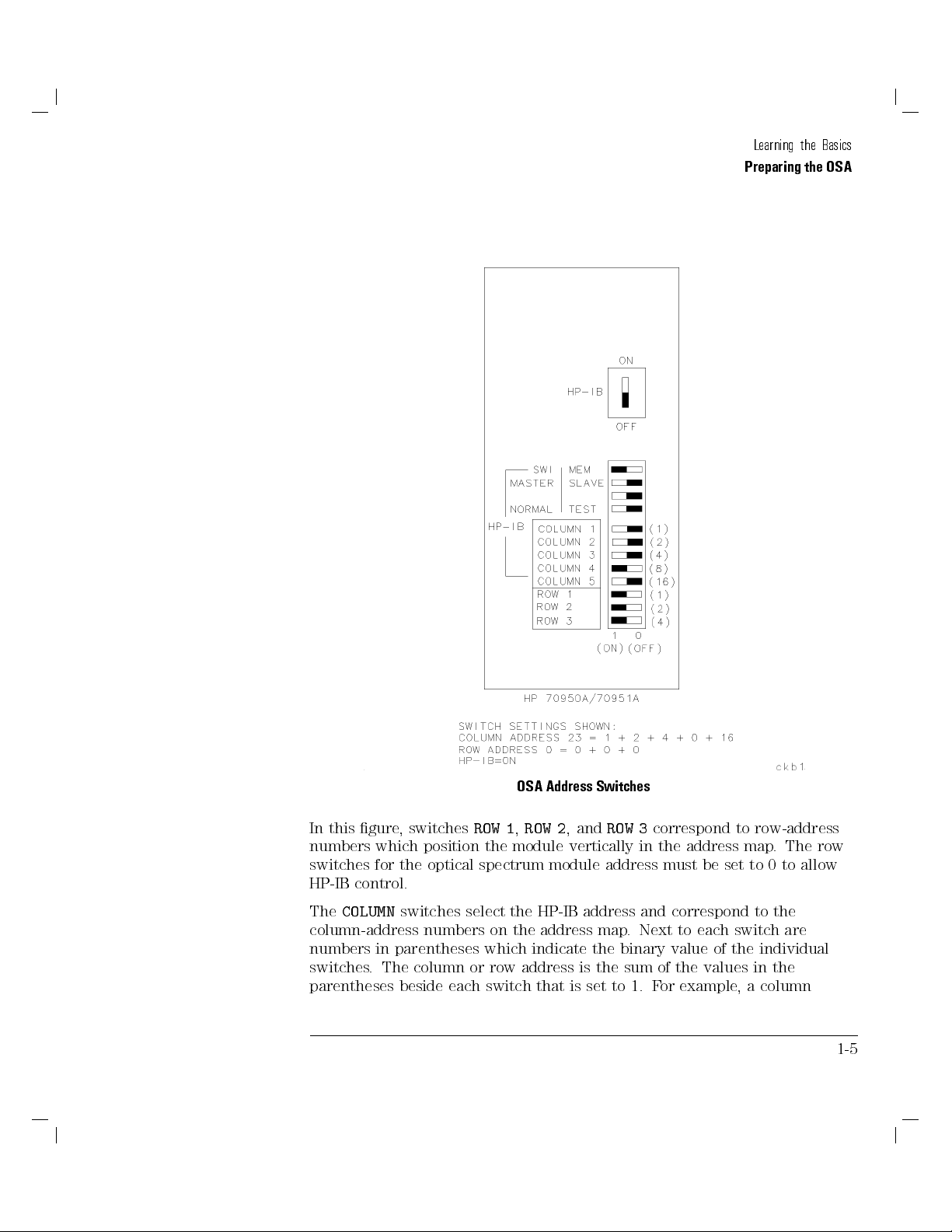
illustration below
In the
half-white (on
position).
, the
rectangles
half-black
are
(o
position)
and
1-4
Page 27
Learning the Basics
Preparing the OSA
OSA Address Switches
In this gure, switches
numbers
switches
control.
HP-IB
The
COLUMN
which
for
position
optical
the
switches select the HP-IB address and correspond
ROW 1,ROW 2
module
the
spectrum
module
,and
ROW 3
vertically
address must
column-address numbers on the address map
numbers in parentheses
switches. The column or
parentheses beside each switch that is
which indicate the binary value of the individual
row address is the sum of the values in the
set to 1. F
correspond to row-address
.
be
set
map
to
0
in the
address
to the
. Next to each switch
or example
, a column
The
to
are
row
allow
1-5
Page 28
Learning the Basics
Preparing the OSA
address of 23 is selected by setting column switches 1, 2, 3, and 5 to 1, and
setting column switch 4 to 0. (23 = 1 + 2 + 4 + 0 + 16.)
Illegal Addresses
HP-IB address 31 and HP-MSIB address 0, 31 are illegal and cannot be used.
following
the
Set the
list:
following OS
:
:
:
::
::
HP-IB
SWITCHES/MEMORY
MASTER/SLA
NORMAL/TEST
:
VE
Amodule
:
:
:
:
:
:
:
:
:
:
:
:
:
switches
:
:
:
:
:
:
:
:
:
:
:
:
:
:
:
:
::
::
:
:
:
:
::
::
:
:
:
:
:
:
:
::
:
:
:
:
:
:
:
to
:
:
:
:
:
:
:
:
:
:
:
::
::
:
:
:
:
:
:
:
:
:
:
:
:
:
:
:
:
:
:
:
:
:
:
:
:
:
:
:
:
:
:
:
:
:
:
:
:
:
:
:
:
:
:
:
:
:
:
:
:
settings
the
shown
:
:
:
:
:
:
:
:
:
:
::
::
:
::
::
:
:
:
::
:
:
:
:
:
in
:
:
:
:
:
:
:
:
:
:
:
:
::
::
:
:
:
MEMORY
:
:
:
:
:
:
:
:
:
:
:
:
:
MASTER
:
:
:
:
:
:
:
:
:
:
:
:
:
NORMAL
:
:
:
:
:
:
:
:
:
:
:
:
:
ON
the
On
STEM
SY
ALK
T
TEST
a
or
F
Optical
1-6
display
CONTROLLER
Y
ONL
MODE
complete
Spectrum
mainframe
:
:
:
:
:
:
:
:
:
:
:
:
:
:
:
:
:
:
:
discussion
Analyzer
module
or
:
:
:
:
:
:
:
:
:
:
:
:
:
:
:
:
:
switch
of
Installation
:
::
:
:
:
:
::
:
,
::
:
:
:
:
:
:
:
::
settings
three
:
:
:
:
:
:
:
:
:
:
:
and
switches
:
:
:
:
:
:
:
:
:
:
:
:
:
,
V
:
:
:
:
:
:
:
:
:
:
:
:
:
:
:
:
:
:
:
:
:
:
:
to
refer
erication
should
:
:
:
:
::
:
:
:
:
:
:
:
the
Manual
set
be
:
:
:
:
:
::
:
:
:
:
:
:
:
:
:
:
:
:
:
:
:
:
:
:
:
::
::
71450B/1B/2B
HP
.
as follows:
(OFF)
0
:
:
:
(OFF)
0
:
:
:
(OFF)
0
:
:
:
Page 29
Learning the Basics
Preparing the OSA
To prepare the OSA
1. Connect an HP-IB cable between the computer's HP-IB connector and the
HP-IB connector on the HP 70000 modular measurement system's rear
panel.
HP 70950B/1B/2B OSA modules do not have an HP-IB connector.
Use the connector that is located on the mainframe in which the module
is installed. Be careful not to confuse the display or mainframe's HP-IB
connector with any connectors that may be present on the rear panel of
2.
3.
On
Turn
map
any modules
press
A,
OS
the
front-panel
the
.
in the
4
DISPLA
HP
knob
70000
and
,
5
Y
until
modular
then
OS
the
measurement
N
N
N
N
N
N
N
N
press
Address
module
A
N
N
N
N
N
N
NN
NN
NN
NN
N
N
N
appears
system.
N
N
N
N
N
N
N
N
N
N
.
Map
the
in
address
The
module
Ensure
4.
70205
HP
Reset all
5.
and
Most
key
on, to reset it.
HP-IB
is
that
or
instruments
on
then
peripherals
you
If
.
address
listed.
SYSTEM
the
70206
HP
again.
are
identical
is
The
display
connected
plotters
like
not sure
to
be
must
A
OS
CONTROLLER
modules)
to
printers are
or
how to
reset a
the
the
address
shown
switch
is
bus
device,
set
by
map
row
in
the
on
0
to
turning
reset by
0
HP
(OFF).
cycle
column
the
of
70004A
the
pressing a
power
its
where
map
line
.
display
power
reset
o,
the
(or
o
then
1-7
Page 30
Learning the Basics
Preparing the OSA
To change the HP-IB address using switches
The HP-IB address is forced to the switch address setting when the OSA
module SWITCHES/MEMORY selector is set to SWITCHES.
NOTE
The SWITCHES setting must be selected. The MEMORY setting is the factory default setting.
1.
2.
3.
4.
Turn
mainframe
the
Locate
the
Set
sure
Be
line-power
any
o
.
switches
the
SWITCHES/MEMORY
three
the
,
the
on
switches
(OFF).
5.
Set
the
F
ve
the
numbers
example
or
COLUMN
in
,
switches
parenthesis)
the switches
to set
1, 2, 3, and COLUMN 5 to 1 (ON).
and
top
labeled
remove
the
of
selector
so that
add up
HP
the
module
the
to
RO
1,
W
RO
their added
to the
HP-IB value
for address
70950B/1B/2B
.
SWITCHES
and
2,
W
values
that you
23, set
switches
module
position.
3
W
RO
indicated
(as
from
set
are
want.
COLUMN
to
0
by
1-8
Page 31
Learning the Basics
Preparing the OSA
To change the HP-IB address from the front panel
The HP-IB address can be changed at the front panel when the OSA module's
SWITCHES/MEMORY switch is set to MEM. (This is the default factory
setting.)
1.
Press
4
DISPLAY
NNNNNNNNNNNNNNNNNNNNNNNNNNNNNNNNNNN
5
,
Address Map
.
2. With the front-panel knob, position the box around the OSA module, then
3. Enter
The
address
the
NNNNNNNNNNNNNNNNNNNNNNNNNNNNNNNNNNNNNNNNN
press
HP-IB ADDRSET
HP-IB
the
NN
NN
NN
NN
N
N
N
N
N
N
N
N
N
ENTER
.
current HP-IB
map.
HP-MSIB
address
address
address
Changing
of
the
the
.
using
shown
is
HP-IB
module
front-panel
the
inside
address
.
the
from
numeric
A
OS
the
keypad,
module
box
front-panel
on
does
then
the
not
press
aect
1-9
Page 32

Beginning Your Program
Programs should begin with system-level and OSA commands that initialize
the system. Three such commands are discussed here: CLEAR, IP, and
CLRDSP.
The CLEAR command is an HP BASIC command that resets a device on HP-IB
to a known state. As an example, CLEAR 723 clears the device (the OSAin
this case) at address 23 on interface 7. CLEAR erases the OSA's input buer,
interrupts most incomplete operations, and prepares the OSA to receive
instructions
The instrument-preset
to a
OSA
processes
information
.
known state
Refer to
.
the IP
on
command, IP
and provides
Chapter
IP in
command.
,sets
good
a
\Language
7,
all of
starting
analog
the
point
Reference"
parameters
measurement
all
for
complete
for
of
the
CLRDSP
The
CLRDSP
graphics
Graphics
graphic
command
erases
also
execute
gives
,
more
window
,"
presentations
clears
stored
graphics
CLRDSP
information
.
graphics
any
from
discriminately
about
from
memory
,
.
initializing
such
Chapter
the
display
the
To initialize the bus and the OSA
Place the following commands at the start of your program.
10 CLEAR 723
20 OUTPUT
OUTPUT
30
723;"IP;"
723;"CLRDSP;"
Initialize the bus.
OS
Initialize
Clears any
the
user
A.
graphics
.
screen.
item
an
as
\Creating
5,
analyzer
Because
or a
display
for
1-10
Page 33

Sending Commands
The commands listed in Chapter 7 are sent to the OSA as ASCII strings.The
method used depends on the programming language and environment. The
examples in this book use the HP-BASIC language with an HP 9000 Series 300
technical computer. Using HP-BASIC, the following example shows an output
statement to send a command to the OSA:
10 OUTPUT 723;"CENTERWL 1300NM;"
Set the center wavelength.
Be sure to place a semicolon between commands and at the end of any
command
string.
ectra
V
HP
an
Using
programming
(and
in
IOOUTPUTS(723L,"CENTERWL
by
a
commands
units
analyzer
Most
followed
computer
the
),
C
rst
and
code
HP-IB
the
with
command
same
1300NM;",15);
function,
activate
a
a command
Interface
could
then
terminator:
be
and
sent
enter
Command
follows:
as
a
Library
number
The number within the quote eld must be a string of decimal numbers plus
an optional decimal point and may be preceded by a minus or plus sign.
Either xed- or oating-point notation may be used. F
\1.23E4", and \12300" each enter the same number
data entry
.
. A
or example
units code follows a
, \12.3E3",
1-11
Page 34

Learning the Basics
Sending Commands
Wavelength
Time
Current
Measurements
Ratio
ower
P
Decibels
relative
Units Codes
units.
to
Units Code
Meters M
Millimeters MM
Micrometer UM
Nanometer NM
Angstrom ANG
Picometer PM
Second S
Millisecond MS
Microsecond US
Ampere A
Milliampere MA
Microampere UA
Decibel DB
att
W
W
Milliwatt MW
Microwatt UW
Nanowatt NW
Picowatt PW
(dBm)
Milliwatt
1
DBM
1-12
Page 35

Learning the Basics
Sending Commands
To send commands to the OSA
1. Locate the appropriate commands in Chapter 7.
2. Construct a ASCII string of the commands, placing a semicolon between
each command in the string.
3. Use your programming language's output statement to send the command
string to the address of the OSA.
1-13
Page 36

Returning Data to the Computer
Data is requested from the OSA using a query. Queries usually take the
form of a command with the question-mark character.For example,
CENTERWL?
requests the OSA's center wavelength setting. The syntax
diagrams in Chapter 7 document available command queries. Most command
queries and variable queries are normally sent in the form of ASCII strings.
However, binary query results are returned for some commands. It is your
responsibility to allocate memory for returned values in your application.
the
or
in
level
the
returns
A
OS
The
following table
(RL) for
amplitude
some functions
units
information
. Units
(MKREAD,
decimal
as
are determined
, such
as the
AUNITS).
values
by the
marker
settings
the
,
in
scale
the
units
of
(LN,
the
LG),
shown
reference
Units
Fundamental
Unit
Measured
Parameter
Data
Current Ampere
y
Frequenc
ower
P
Hertz
dBm
Ratio dB
Time Second
avelength
W
Meters
Trace information that has been manipulated with math and move
commands, or has been formatted with the MDS (measurement data size) or
TDF (trace data format) command may be returned in other units. Refer to
Chapter
Trace
the use of markers
commands. The next example marks trace
wavelength and amplitude values at the marker
executed, a value must be stored in the computer
2.
information
either
,
dierent
returned
is
directly as trace data with the TRA, TRB
,or
two
ways
A with a marker and returns the
. Note
.
indirectly with
, or TRC
that for every query
1-14
Page 37

Learning the Basics
Returning Data to the Computer
10 CLEAR 723
20 OUTPUT 723;"IP;SNGLS;TS;"
30 OUTPUT 723;"CENTERWL 1300NM;SPANWL 10NM;RL -5DBM;"
40 OUTPUT 723;"TS;"
50 OUTPUT 723;"MKPK HI;"
60 OUTPUT 723;"MKWL?;"
70 ENTER 723;W
80 OUTPUT 723;"MKA?;"
90 ENTER 723;A
100 W=W/1.E09
110 PRINT W,A
To return the amplitude of the 400th element of trace A, you would send the
following:
OUTPUT
40
OUTPUT 723;"TRA[400]?;"
50
ENTER
60
PRINT
70
723;"SNGLS;TS;;"
723;N
N
return
o
T
the
amplitude
of
A
Print
elements
all
ssign
commands:
30
40
60
70
Array
DIM
OUTPUT
OUTPUT
ENTER
(1:800)
723;"SNGLS;TS;;"
723;"TRA?;
723;Array(*)
Declare
eturn
R
Store
Initialize analyzer.
Set measurement range.
Sweep trace A.
Mark highest signal level.
Return wavelength at marker.
Assign wavelength to computer variable.
Return amplitude at marker.
Assign amplitude to computer variable.
Convert wavelength from meters to nanometers.
Print values.
amplitude
.
value
in
computer
amplitude
amplitude
trace
trace
computer
to
A
array
points
of
values
send
for
variable
the
storage
trace
in
in
.
following
800
of
A.
a computer
values
array.
.
The
Data
data
FETCH
is
transfer
command
returned
and
in
processing.
returning trace data.
returns
binary
while
Refer
the
the
trace
sweep
to
data
progresses
Chapter
the currently
for
more
for
2
Use
.
information
active trace
FETCH
to
.
speed
on
1-15
Page 38

Learning the Basics
Returning Data to the Computer
To query a value
1. Allocate a variable to hold the data returned by the query.
2. Use an output statement to send the query to the OSA.
3. Enter the returned data to the variable.
For example, to return the sensitivity setting, send
OUTPUT 723;"SENS?";"
ENTER 723;S
Send the sensitivity query string.
Assign value to computer variable.
SENS?
.
1-16
Page 39

Using Commands as Arguments
Some OSA commands accept other commands as arguments. The following
example shows the MKA command used as an argument for the MOV
command.
10 OUTPUT 723;"MOV DL,MKA;"
The value of the command MKA is returned as input to the calling command,
MOV. Commands that accept command arguments have syntax diagrams
that show
using
value
example
or
F
returns
not follow
Do
example shown
the
predened variable
the
termination
predened function
command
a
the
sure
Be
.
TRA
the
,
the ftieth
the
character.
argument,
an
as
returned
value
command
element.
argument
above
DL.
,
The
as an argument. Refer to Chapter 7. When
similar
is
the
for
a
in
termination
or
terminated
not
calling
, but
trace
amplitude
MO
the
command
the
,
Notice
ending
the
is
returns
V
MO
that
semicolon
returned
value
appropriate
the
all
?
a
with
MKA
the
is
moves
terminates
data
marker
query
the
to
command.
TRA[50]
character
value
?
a
with
command.
V
In
.
into
or
command argument
a
use
o
T
The calling command must list
predened function
in its syntax diagram
for the argument.
Do not follow the argument command with a?or termination character.
1-17
Page 40

Using the MOV Command
It is recommended that the MOV command be used to execute all
programming commands that load variables. Using the MOV command is
faster and avoids displaying text on the analyzer screen. For example, send
the following to set the reference level to010 dBm:
OUTPUT 723;"MOV RL,010DBM;"
1-18
Page 41

Controlling Program Timing
Most remote controlled measurements require control of the sweep.TheTS
(take sweep) command initiates a sweep when the trigger conditions are met.
When TS is executed as part of a command sequence, the analyzer starts and
completes one full sweep before the next analyzer command is executed. Use
the SNGLS (single sweep) command to maintain absolute control over the
sweep and to reduce execution time. Once SNGLS activates the single-sweep
mode, TS can be used to initiate a sweep only when necessary.
remote
many
Since
information with
TS becomes
measurement range
input signals
settings
to
commands
When
the
the
range
command in
or
computer or
the
developing
N
N
N
N
N
N
N
N
N
NN
N
N
SINGLE
.
trace
The
.
OUTPUT
20
OUTPUT
30
OUTPUT
40
.
N
N
N
N
N
NN
N
N
N
N
N
N
N
N
N
N
N
N
N
N
SWEEP
following
The
data
trace
40
line
723;"IP;SNGLS;TS;"
723;"CENTERWL
723;"TS;"
commands
changes.
change,
processed by
measurement
N
N
N
N
key
simulate
to
examples
updated
not
is
executed.
is
1300NM;SPANWL
information,
process
trace
important whenever
the
with
the
trace
Use TS
but
other
algorithms
to update
before
commands
eect of
the
demonstrates
settings
the
with
10NM;"
the input
trace
information
trace
like
,
front-panel
the
TS
the
changing
in
ctivate
A
Change
Measure
updating
after
command
the
line
single
measurement
with
trace
or
signal
analyzer
the
returned
is
marker
or
math
controls
updating
measurement
the TS
until
30
.
sweep
range.
A.
trace
Note that SNGLS cannot be substituted successfully for TS in all analyzer
programs. In the following program, TS is executed
changed, but
for TS, SNGLS would initiate a sweep,but
before
trace information is processed. If SNGLS were substituted
MKPK HI
after
analyzer settings are
would be executed before
the completion of the sweep.
30
OUTPUT
723;"CENTERWL
1300NM;SPANWL
40
OUTPUT
723;"TS;"
50 OUTPUT 723;"MKPK HI;"
10NM;"
Change
Update
measurement
.
trace
Place marker on highest signal
range
level.
There are two commands that change the
measurement range indirectly
MKCWL and MKRL. They set the center wavelength and reference level
equal to
the marker wavelength and amplitude
, respectively
. If valid
,
,
use
.
1-19
Page 42

Learning the Basics
Controlling Program Timing
trace information is needed, a TS command must be executed after these
commands are executed. In all cases, executing TS invokes at least one entire
sweep.However, TS invokes more than one sweep when certain commands
are active, such as video averaging (VAVG) or marker tracking (MKTRACK).
Program timing can also be controlled with the RQS, DONE, and WAIT
commands. The RQS command interrupts the computer operation when
the analyzer has attained a predened state. The DONE command allows
the program to hold o the execution of subsequent commands until the
OSA returns a \1" in response to the query. The WAIT command suspends
program operation for a specied time.TS,RQS, and DONE are used often
to synchronize data acquisition or the analyzer state with other events.The
command,
AIT
W
program.
the
duration
you
give
on
program
The
of displayed
observe
to
time
other
the
messages
events
hand,
examples
use
or
,
on
is
the
used
this
in
AIT
W
display
improve
to
manual
delay
to
.
human
W
use
program
AIT
interface
control the
to
execution
with
to
1-20
Page 43

Entering Data from the Front Panel
Data may be entered from the front panel when the OSA is under remote
control by using theEP(enable) argument with a command. EP halts
execution of analyzer commands so that values may be entered with the
front-panel numeric keypad, step keys, knob, and unit-code keys. Data may
be entered from the front-panel until the
NNNNNNNNNNNNNNNNNNNNNNNNNNNNNNNNNNNNNN
ACCEPT VALUE
key is pressed. The
syntax diagrams in Chapter 7 provide the commands that can be followed by
EP.
allow front-panel
o
T
argument with
EP
the
Use
OUTPUT 723;"LG
40
50
OUTPUT
723;"LG
20DB;"
EP;"
data entry
compatible
a
log
the
Set
Change
a
the
number,
command.
20
to
scale
with
scale
log
press
then
dB/division.
front-panel
the
F
F
F
F
F
F
F
F
F
F
F
F
F
F
F
F
F
F
F
F
F
ACCEPT
VALUE
Enter
.
keys
F
F
F
F
F
FF
F
F
F
1-21
Page 44

Controlling Advanced Measurement Programs
NNNNNNNN
The
FP
,
NNNNNNNNNNN
DFB
,and
NNNNNNNNNNN
LED
measurement keys available under the
4
USER
5
menu activate advanced measurement routines.You can also make these
measurements over HP-IB. Refer to Chapter 7, \Language Reference" for
more information about the following advanced measurement program
commands:
\FP " for characterizing a Fabry-Perot laser source.
\DFB " for characterizing a distributed feedback laser source.
guide
Chapter
in
.
.
needed.
as
manually
,
7,
\LED"for
how
learn
o
T
Chapter
to
refer
Making
advanced
make
o
T
Connect the
Follow
the instructions
characterizing
measure
to
\Measuring
3,
advanced
measurements
source
laser
light-emitting
a
characteristics
the
Signals"
in
measurements
HP-IB
over
A.
OS
the
to
to
refer
or
,
below
diode
of these
the
connect
,
commands
the
laser source
laser sources
users'
A
OS
over
HP-IB
HP-IB
\Language Reference", of this manual:
1. To measure a Fabry-Perot source and obtain measurement data, enter the
following command lines:
30 OUTPUT 723;"AUTOMEAS;"
40 OUTPUT 723;"FP_;"
OUTPUT
50
o measure a distributed feedback laser source and obtain measurement
2. T
723;"FP_
?;"
Locate and display the output of the laser source.
Measure the output of the Fabry-Perot source.
charac-
the FP
return
the
Query
terization
instrument
data.
and
data, enter the following command lines:
30 OUTPUT 723;"AUTOMEAS;"
40 OUTPUT 723;"DFB_;"
50 OUTPUT 723;"DFB_ ?;"
Locate and display the output of the laser source
Measure the output of the laser source
.
Return the measurement data.
,
.
1-22
Page 45

Learning the Basics
3. To measure an LED laser source and obtain measurement data, enter the
following command lines:
30 OUTPUT 723;"AUTOMEAS;"
40 OUTPUT 723;"LED_;"
50 OUTPUT 723;"LED_ ?;"
4. To set the right and left power integration points on a signal, enter the
following command lines:
10 OUTPUT 723;"CENTERWL 900NM;"
20 OUTPUT 723;"TS;"
30 OUTPUT 723;"AMPMKR010,dB;"
Locate and display the output of the laser source.
Measure the output of the LED source.
Return the measurement data.
Set the center wavelength to 900 nm.
Update the current trace.
Set the right and left power integration
points010 dB from the peak.
1-23
Page 46

Learning the Basics
Page 47

2
Using
ariables
V
and
Traces
Page 48

Using Variables and Traces
This chapter can help you learn to create variables and process both
predened and user-dened trace arrays.
Predened traces, for example trace A, exist permanently in reserved
memory.
User-dened variables and trace arrays are created by the user, given
preset values, and stored in internal memory. User-dened variables and
trace arrays remain in internal memory, even when power is turned o.
Reserved
creating
When
(as
words
dening
addition,
In
reserved
Words
listed
process
an
words
user-dened
Chapter
in
can
and
names
y
the
until
variables
8,
disrupt
created
are
y
ables
\T
OSA
with
erased
traces,
and
and
operation.
TRDEF
from
Charts")
FUNCDEF
,
internal
do not
for
memory
names.
AC
,
use the
TDEF
.
permanently
Reserved
other
or
OSA
stored
usage interrupts
word
ARDEF commands
V
reserved
the
become
2-2
Page 49

Using Variables and Traces
Contents
Dening Variables
To create a user-dened variable
To erase a user-dened variable
Dening Traces
To create a user-dened trace
To erase a user-dened trace
Using Amplitude Data
To select the amplitude units
:::::: ::::::: :::::: ::::::: ::::::: :::::: ::::::: ::::::: ::
:::::: ::::::: ::::::: :::::: ::::::: ::::
::::::: :::::: ::::::: ::::::: :::::: :::::
::::::: ::::::: :::::: ::::::: ::::::: :::::: ::::::: ::::::: :::
:::::: :::::: ::::::: ::::::: :::::: ::::::: :
:::::: ::::::: :::::: ::::::: ::::::: :::::: ::
::::: ::::::: ::::::: :::::: ::::::: ::::::: :::::: :::::
:::::: :::::: ::::::: ::::::: :::::: ::::::: ::
To convert measurement and parameter units
To return wavelength and position values
Formatting Trace-Data Output
Commands
Move
and
Math
Using
:
:
:
1
Rule
Math
Trace
::
Trace Math
Math
Trace
Math
Trace
Rule 2
Rule 3
Rule 4
::
::
::
:
:
:::::: ::::::: :::::: ::::::: ::::::: :::::: ::
:
:
:
:
:
:
:
::
::
::
::
:
:
:
:
:
:
:
:
:
:
:
:
:
:
:
:
:
:
:
:
:
:
:
:
:
:
:
:
:
:
:
:
:
:
:
:
:
:
:
:
:
:
:
:
:
:
:
:
:
:
:
:
:
:
:
:
:
:
:
:
::::::: ::::::: :::::: :::
::::::: :::::: ::::::: ::::::: :
:
:
:
:
:
:
:
:
:
:
:
:
:
:
:
:
:
:
:
:
:
:
::
::
:
:
:
:
:
:
:
:
:
:
:
:
:
:
:
:
:
:
:
:
:
:
:
:
:
:
:
:
:
::
::
::
::
:
:
:
:
:
:
:
:
:
:
:
:
:
:
:
::
::
:
:
:
:
:
:
:
:
:
:
:
:
:
:
:
:
:
::
::
:
:
:
2-4
2-5
2-5
2-6
2-7
2-7
2-8
2-9
2-9
2-9
2-10
2-15
:
:
:
:
:
:
:
:
:
2-16
:
:
:
:
::
::
2-17
::
::
:
:
:
:
:
2-17
::
:
:
:
:
:
:
:
2-19
::
:
:
:
:
:
:
:
2-3
Page 50

Dening Variables
The OSA retains in reserved memory a set of predened variables.Each
predened variable stores a current OSA setting or state. Note the two
characteristics of these variables:
1. Values depend on current instrument settings.
2. Names are identical with associated programming commands.
Programming commands which have the same name as a predened
variable
OSA's
load
center wavelength.
variable
that
CENTERWL. Predened
your programs
available
queried
arguments
to
return their
to
many
to
of
example
or
F
.
CENTERWL also
variables reside
. Both
values to
OS
the
Partial
predened
the
commands
A
of
List
the
,
in reserved
computer
listed
Predened
command
loads the
user-dened
and
Also
.
in
ariables
V
CENTERWL
predened
memory and
variables
,
chapter 8.
sets
variable
are
variables
be
can
always
used
the
can
be
as
CENTERWL CNVL
MKA MKAC
MKP MKP
TE
A
NST
OSS
T
AUSE
DL INZ L
MKAL MKAR MKN
MKPX MKT MKTV
RB RBR RL RLPOS
ROFFSET SP SS ST ST
G
TWL
AR
STOPWL TH VB VTL WLOFFSET
Use the
VARDEF
command to create and store user-dened variables in
internal memory. User-dened variable names are from 1 to 12 characters
executed. Use
from
is
internal
memory
.
long
PURGE
and
or
assigned
are
DISPOSE
values
erase user-dened
to
immediately
VARDEF
after
variables
2-4
Page 51

To create a user-dened variable
Use the
10 OUTPUT 723;"VARDEF MY_VAR,0;"
VARDEF
command.
Create variable called MY VAR and assign it
a value of 0.
Using Variables and Traces
Dening Variables
To
erase
Use
10
DISPOSE
the
OUTPUT
user-dened
a
command.
723;"DISPOSE
variable
MY_VAR;"
2-5
Page 52

Dening Traces
The OSA stores data for traces A, B, and C in reserve-memory trace arrays.
These arrays comprise a series of data points (elements) that contain
amplitude information. Position units describe the position of an element
(point) along the horizontal axis of a trace. The point at the left end of
the trace has a position-unit value of 1. The point at the right end of an
800-point trace has a position-unit value of 800. Whenever trace A, B,orC is
swept, the analyzer updates the trace's array with new data. You can create
your own user-dened trace arrays in
and
command. Unlike
The
units
units
Predened
trace
any
of
lengths
trace
command converts
POSU
The
.
meters,
to
length
trace
to
from
command converts
WLU
user-dened
and
800
is
Use
.
their
internal
traces A,
or in
elements
the
preset
memory
B,
zero-span
traces
.
TRPST
or
IP
.
values
.
the wavelength
Use
Use
internal memory
user-dened
C,
point
a
to
,
mode
be
can
TRDEF
the
preset)
(trace
PURGE
on
units
to
3
command
DISPOSE
or
point
of a
trace
a
time
of
2048
command
using the
traces
on
indicated
.
elements
to
to
cannot
trace
a
in
The
.
change
to reset
a user-dened
erase
TRDEF
swept.
be
position
to
position
default
the length
the
be
User-dened
10
20
example
array
CLEAR
OUTPUT
following
trace
trace
called
723
723;"IP;"
names
,
TRA
can
measurement
CE
Z.
30 OUTPUT 723;"SNGLS;TS;"
40 OUTPUT 723;"TRDEF TRACE_Z,800;"
50 OUTPUT 723;"MOV TRACE_Z,TRA;"
2-6
from
results
to
1
are
characters
12
transferred
Initialize
long.
a
to
analyzer
user-dened
.
the
In
Activate single-sweep mode and sweep
once.
Create user-dened trace array.
Move copy of trace A contents into
TRACE Z.
Page 53

To create a user-dened trace
Use the
10 OUTPUT 723;"TRDEF TRACE_Z,1000;"
TRDEF
command.
Using Variables and Traces
Dening Traces
T
o
erase
Use
10
the
OUTPUT
user-dened
a
DISPOSE
command.
723;"DISPOSE
trace
TRACE_Z;"
2-7
Page 54

Using Amplitude Data
Measurement results are expressed in either parameter units or measurement
units. A parameter unit is a standard scientic unit such as Watts, decibels,
seconds, hertz, amperes, and ohms. Measurement units are an internal
representation of the data. Measurement units apply only to traces and trace
elements. In its preset state, the analyzer returns all measurement results in
parameter units.
The amplitude parameter units used are shown in the following table. Use
display
the
AUNITS
command
annotation and
change
to
returned by
the
queries to
amplitude
active
the computer
.
units
shown
in
Amplitude
Parameter
Units
Units
dBm
for
,
dB
W
,
mW
,
W
for
(zero)
0
units
the
are
(reference
top
unit
dened
one
is
as
level).
hundredth
or
F
a
of
Decibels
Watts
trace
linear
For
the
the bottom
of
logarithmic trace
information,
and
display
,
information,
measurement
10,000
measurement
a
dBm:
measurement
unit
=
(
val
ue in
dB
m
(
)
)
100
Thus,a010 dBm value is equal to01000 measurement units:
0
1000 measurement units =010 dBm (100)
The measurement-unit range is restricted to integers between +32,767 and
32,768.
0
equals
decimal
Use the
parameter-unit values
Since measurement
measurement
1012
0
rounded
values
0
1012 measurement units =
AMPU
are
command to convert measurement-unit values to
. The
to measurement-unit values
units
units
the
to
MEASU
.
10.115
0
restricted
are
1011.5
0
not
,
nearest
0
10.115 dBm (100)
integer
integers
to
measurement
.
,
units because
command converts parameter-unit values
dBm
2-8
Page 55

Using Variables and Traces
Using Amplitude Data
To select the amplitude units
Use the
AUNITS
command.
To convert measurement and parameter units
parameter
to
convert
command
AMPU
the
Use
MEASU
the
Use
command
to
to
convert
measurement
parameter
units
units
measurement
to
units
units
.
.
return
o
T
the
Use
wavelength
the
Use
point.
wavelength
command to
POSU
.
value
command determines
WLU
position
and
determines the
the wavelength
trace
values
that
point
value of
corresponds
trace
given
a
to
2-9
a
Page 56

Formatting Trace-Data Output
The trace-data format (TDF) command controls the format of trace-amplitude
data output from the OSA. All the available format modes return amplitude
information in measurement units except for
TDF P
, which returns
parameter units. The output formats are summarized in the following table.
(Parenthetical numbers in the table are decimal values representing binary,
8-bit numbers.)
Trace Data Output Formats for Amplitude Information
Output
Format
Command
P
TDF
ASCII
Returns
followed
is
output
end-or-identify
decimal
(EOI)
y line
b
OSA
value
feed (ASCII
.
Output
alues
V
are
in
code
parameter
and
10)
units.
Data
race
T
Amplitude
+10.00
Element
of +10
dBm
output.
(determined
alues are
V
rst.
.
eld
data
command).
units.
y
b
and
Data
length of
+1000
(232)
(3)
(0)(2)
(#)(A)
(#)(I) (3) (232)
(3)(232)
TDF
TDF
TDF
TDF I
measurement
in
are
alues
V
.
value
feed
series
integer
ASCII
(ASCII
binary
command),
of
y
b
alues
V
code 10)
value
units.
one
bytes
and
\#"
are
one
as
with
Sends
two
or
determined
is
\A"
measurement
in
and
most
and
EOI
or
EOI
8-bit
follow
8-bit
two
signicant
with
ytes
b
y
b
b
two
data
b
last
(A-block
the
ytes
units.
ytes
yte
b
yte
b
MDS
representing
M
B
A
Returns
Line
Returns
MDS
the
measurement
in
Sends
number of
the
preceded
is
data eld.
Sends a series of one or two 8-bit bytes (I-block data eld and
the number of bytes is determined by the MDS command). Data
is preceded by \#" and \I". Values are in measurement units.
Sends EOI with last byte.
TDF
formats
P
data as
ASCII,
preset (IP) activates the
command species the kind of
decimal
format, and the A
TDF P
parameter units
for linear trace information and dBm for
values
logarithmic trace information. A
line feed (ASCII code 10) follows data output.
format is convenient because it returns
sent with line feed. The
is
TDF P
parameter
in
UNITS (amplitude units)
. The default units are volts
The end-or-identify state (EOI)
units
Instrument
.
parameter-unit values, but it is the slowest of the data-format modes.
2-10
Page 57

Using Variables and Traces
Formatting Trace-Data Output
TDF M
formats data as ASCII, integer values in measurement units. (Thus, the
AUNITS command has no aect on returned data.) A line feed (ASCII code
10) follows data output. The end-or-identify state (EOI) is sent with line feed.
The
TDF M
format is faster than the
TDF P
format, but requires conversion to
parameter units.
TDF B
formats data in measurement units as binary numbers. Numbers are
transmitted usually as words. (A word is two 8-bit bytes.) The results are
transmitted in the following order:
The most signicant byte is sent rst.
The least signicant byte is sent next.
.
byte
last
the
with
sent
is
EOI
one
numbers
words
elds
bytes
or
they
precedes
bytes
with
(MDS)
as
.
\# I"
or speed
F
used
be
may
(MDS
byte
large
too
size
data
the
Instrument
and
A
TDF
formats
Both
as
)
B
MDS
(
data
the
with
indicate
the
returned.
sends
and
at
B).
to
TDF
a
On
EOI
be
preset
cost
the
consolidate
to
However
contained
not
is
format
I
return
block
number
and
A
#
other
the
(end
accuracy
of
the
since
,
one
in
recommended,
data
same
However,
bytes
bytes
words
into absolute
or
selects
(IP)
the
of data.
of
two
hand,
identify)
or
measurement-data-size
the
,
information
math
trace
the
,
byte
especially
as
data, binary
of
kind
the
words
specify
that
TDF
the
the
with
contained
operations
bytes
of
use
during
default data
the
indenite
and
words
formats
dier
returned. The
number
the
format
I
last
precedes
byte
of
command
word
a
in
produce
often
instead
trace-math
.
size
block-data
MDS
(
the
in
format
TDF A
data
of
data
the
The
data.
into
of
operations
)
W
way
block-data
formats are available for compliance with IEEE standards. They have the
same limitations as the binary format,
TDF B
, when bytes are chosen as the
measurement data size.
The following table shows an HP-IB transmission sequence for each format.
Each one transmits the +10 dBm amplitude level of a trace element.
ASCII-decimal
the
to
the
in
table
HP
9000
are
200
that
on
or
Remember
information
series
decimal values
though
even
a
,
HP-IB
300 controller
the
decimal
The
.
representing binary
analyzer
number
transmits
is always
parenthetical
, 8-bit numbers
binary or
returned
numbers
.
.
2-11
Page 58

Using Variables and Traces
Formatting Trace-Data Output
Transmission Sequence for Trace-Data Formats
TDF P TDF M TDF B TDF A TDF I
format
The
analyzer
the
concept.
of
computer
the
following table
The
.
Byte 1
Byte 2
Byte 3
Byte 4
Byte 5
Byte 6
1 1 (3) # #
0 0 (232-EOI) A I
. 0 (0) (3)
0 0 (2) (232-EOI)
0 10 (EOI) (3)
10(EOI) (232)
be
must
and programming
(10-EOI)
compatible
with
output
the
examples
format
illustrate
of
this
2-12
Page 59

Using Variables and Traces
Formatting Trace-Data Output
Computer Formats
Analyzer Format Computer-Format Requirements Example in HP BASIC
TDF M Free eld 10 ENTER 723;Amplitude
TDF P Free eld 10 ENTER 723;Amplitude
TDF B Binary. Read twice for each value if data size
10 ASSIGN @Sa TO 723;FORMATOFF
is words. (See MDS.)
20 ENTER @Sa USING \#,W";Z(*)
TDF A Initially read four values (for #, A, and
10 ASSIGN @Sa TO 723;FORMATOFF
length) in any format. Use integer format for
to MDS)
(Refer
follows.
that
data
ounda,Num
@Sa;P
ENTER
I
TDF
following examples
The
return to
for
read
Initially
Use
format.
(Refer
follows.
illustrate the
the computer
two
integer
to
The
.
values
format
TDF)
(for
last
in
I)
#,
data
for
four
example
y
an
that
ways
also
20
ALL
30
ENTER
40
ASSIGN
10
ENTER
20
ENTER
30
trace
shows
INTEGER Z(1:Num
TE
OCA
@Sa;Z(*)
@Sa
@Sa;P
@Sa
data
how
T
oundi
USING
can
O
to
723;FORMA
\#,W";Z(*)
formatted
be
send
b
ytes
b
OFF
T
the
ytes/2)
trace data from the computer back to the analyzer.To return trace data as
decimal numbers in parameter units (TDF P):
10 OUTPUT 723;"TDF P;"
20 OUTPUT 723;"TRA[10]?;"
30 ENTER 723;N
Return amplitude of trace element in parame-
ter units.
Assign value of (010.33) to N.
as
data
10
trace
OUTPUT
723;"TDF
o return
T
20 OUTPUT 723;"TRA[10]?;"
30 ENTER 723;N
To return trace data as
10 INTEGER Z(1:800)
integers
M;"
measurement
in
ctivate
A
units
measurement-unit
format.
M):
(TDF
Return amplitude of trace element in measure-
ment units
Assign value (
.
0
1033) to N.
binary numbers with data size of one word (TDF B).
Declare integer array.
2-13
Page 60

Using Variables and Traces
Formatting Trace-Data Output
20 ASSIGN @Sa TO 723
30 ASSIGN @Sa_fast TO 723;FORMAT OFF
40 OUTPUT @Sa;"MDS W;"
50 OUTPUT @Sa;"TDF B;"
60 OUTPUT @Sa;"TRA?;"
Assign fast I/O path to 723.
Dene data size as one word.
Activate binary data format.
Return amplitude of all trace elements
in measurement units.
70 ENTER @Sa_fast USING "#,W";Z(*)
Load binary values into array Z. \#"
species that line execution is termi-
nated when last ENTER item is termi-
nated. \W" species that items loaded
are words (two bytes).
To return trace data in block-data format with data size of one word (TDF A),
then send data back to analyzer.
to
all
to
.
A
.)
A.
723.
word.
trace
ssign
of
Num
A
. Set
format.
elements.
length,
bytes
bytes
Num
of
in
re-
an
OUTPUT
1
OUTPUT
5
INTEGER Pounda,Num_bytes
10
ASSIGN
20
ASSIGN
30
OUTPUT
40
OUTPUT
50
OUTPUT
60
ENTER
70
ALLOCATE
80
ENTER
90
100 OUTPUT
723;"SNGLS;SP
723;"TS;"
723
TO
@Sa
@Sa_fast
@Sa;"MDS
@Sa;"TDF
TO
W;"
A;"
@Sa;"TRA?;"
@Sa_fast;Pounda,Num_bytes
INTEGER
@Sa_fast;
A(*)
@Sa;"TRDSP TRA,OFF;"
110 OUTPUT @Sa;"TRC";
1MHZ;CF 300MHZ;"
723;FORMAT
OFF
A(1:Num_bytes/2)
Activate
measurement
Sweep
Declare
ssign
A
Dene data
ctivate
A
eturn
R
ssign
A
that
turned
(T
Declare
Store
integer array
Stop display
single-sweep mode
trace
integer
fast
absolute
amplitude
to
#A
the
,
is
computer
to
emporary
array
contents
range
A.
array
path
I/O
as
size
block-data
ounda.
P
number
variables
with
of
.
trace
of
.
one
of
,
length
trace
This line and the next line store
the contents of the integer array in
trace C. The semicolon is required
to suppress carriage-return/line-feed
so that the TRC-command statement
is not terminated prematurely.
120 OUTPUT
@Sa_fast;Pounda;Num_bytes;A(*)
Send
lowed
required
s
A
contents
by
by
the
array
integer
of
TRC-command
fol-
A,
OS
to
length
and
#A
syntax, the @Sa fast format removes
commas that separate the numbers
.
130 OUTPUT 723;"VIEW TRC;"
inside the integer array
View trace C.
.
bytes/2.
.
2-14
Page 61
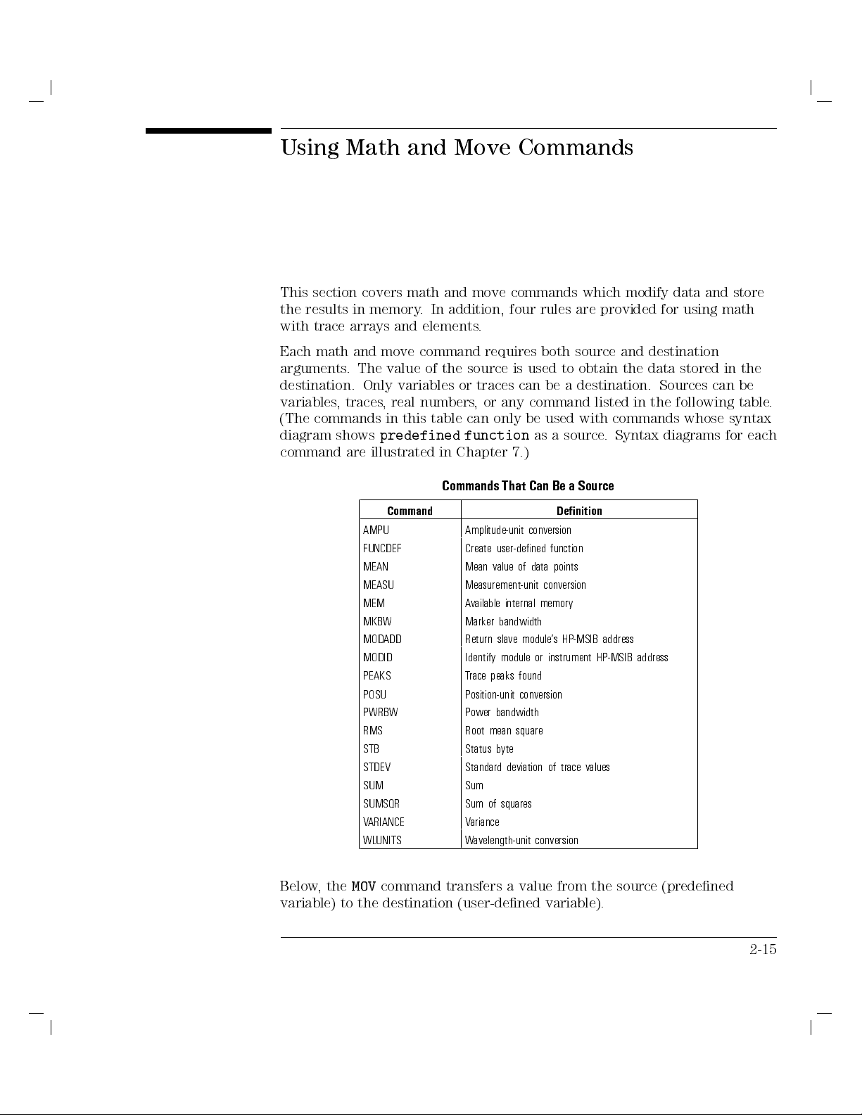
Using Math and Move Commands
This section covers math and move commands which modify data and store
the results in memory. In addition, four rules are provided for using math
with trace arrays and elements.
Each math and move command requires both source and destination
arguments. The value of the source is used to obtain the data stored in the
destination. Only variables or traces can be a destination. Sources can be
variables, traces, real numbers, or any command listed in the following table.
commands
(The
diagram shows
command are
only
can
table
this
in
predefined function
illustrated in
Chapter 7.)
Commands
That
used
be
as a
Can Be
with
source.
a Source
commands
Syntax
diagrams
whose
syntax
each
for
Command Denition
AMPU Amplitude-unit
FUNCDEF Create
MEAN Mean
MEASU Measurement-unit
MEM A
vailable
MKBW Marker
MODADD Return
MODID Identify
PEAKS T
race peaks
conversion
user-dened
data
of
value
internal memory
bandwidth
module's
slave
or
module
found
function
points
conversion
HP-MSIB
instrument
address
HP-MSIB address
POSU Position-unit conversion
PWRBW Power bandwidth
RMS Root mean square
STB Status byte
STDEV Standard
deviation
values
of trace
SUM Sum
squares
ariance
V
of
SUMSQR Sum
ARIANCE
V
WLUNITS Wavelength-unit conversion
MOV
Below,the
command transfers a value from the
variable) to the destination (user-dened variable).
source (predened
2-15
Page 62

Using Variables and Traces
Using Math and Move Commands
10 OUTPUT 723;"MOV WAVELENGTH,CENTERWL;"
The next example uses the multiple command,
wavelength by 10%.
10 OUTPUT 723;"MPY CENTERWL,CENTERWL,1.1;"
Trace Math Rule 1
truncating
void
A
source
the
lost
is
Data
of
,
is
(that
portion
the
information.
moving
when
array
trace
last
the
in
OUTPUT
30
OUTPUT
40
OUTPUT 723;"MOV
50
when
fewer
of
TRACE
,
400
data
length.
trace
a
trace
is
,
points
or
not
array
shorter
the
The
a
data
points)
example
trace
723;"SNGLS;TS;"
723;"TRDEF
TRACE,TRA;"
operated
is
variable
a
in
stored
shows
below
shorter
a
into
than
when
lost
is
TRACE,400;"
on
lost
is
trace
and
When
.
when
how
trace
A,
trace
stored
amplitude
Single
Dene
Copy
destination
a
using
from
into
60
OUTPUT
723;"TS;"
Update
Copy center wavelength value into
WAVELENGTH variable.
MPY
, to increase the center
shorter than
of lesser
active source
new sweep
with
may
user-dened
the
contained
with
trace
information
sweep information.
using an
it
trace
array
is
A
TRA
amplitude
in
updated
is
that is
atrace
length
information
Since
.
information
updated.
.
sweep
user-dened
CE.
with new
trace A
be
400
of
length
trace
lost
elements.
trace
,
A
When a short trace or variable is operated on and stored in a trace of longer
length, the last trace element is extended for operations with the longer
length.
2-16
Page 63

Using Variables and Traces
Using Math and Move Commands
Trace Math Rule 2
Trace elements greater than +32,767 and less than032,768 are truncated.
Math operations are restricted to the legal range of measurement units when
trace arrays or elements form the destination or source.
10 OUTPUT 723;"MPY TRA[100],1000,1000;"
Multiplies 1000 times 1000, then stores
truncated value (32,767) in trace element.
is
use
units
.
a
All
is
3
real number
MEASU
the
express
trace
units
inaccurate
the
Trace
When
array
yield
The
Math
the
or
parameter
source
conversion
manipulated
omitted,
may
In
10.33 dBm.
0
returned data
be lost.
the following
Rule
source
element,
destination
and
necessary
measurement
in
example,
10 OUTPUT 723;"MOV TRB[100],MKA;"
20 OUTPUT 723;"TRB[100]?;"
the
following
In
returns
and
10
example
trace
OUTPUT
uses
amplitude
723;"MOV
values
TRB[100],MEASU MKA;"
20 OUTPUT 723;"TRB[100]?;"
command
numbers
amplitude
.
marker
MEASU
in
or variable
and
preserve decimal
to
dierent
in
information
conversion
the
If
of
factor
a
by
assumed
is
Copy integer value of marker (010)
into trace B element. TRB[100] now
contains010 measurement units.
Return00.1 dBm (false value).
command to
parameter units
Convert
to measurement units
value
TRB[100] now contains
surement units
Return010.33
destination
the
values
making
,
units
is
to
and
100
marking
be
to
preserves
stored
measurement
internally
signicant
signal
a
decimal
.
marker
amplitude
(01033) into trace element.
.
(correct value).
trace
a
is
and
a
and
units
digits
at
values
10.33)
0
(
, then move
mea-
0
1033
is
2-17
Page 64

Using Variables and Traces
Using Math and Move Commands
The following table lists math and move commands that may require the use
of the
MEASU
command.
Math and Move Commands Requiring Conversion with MEASU
Command Denition
ABS Compute absolute value.
ADD Add sources, point by point.
AVG Average source with destination, point by point.
BIT Store or return value of bit.
CONCAT Concatenate traces.
DIV Divide sources, point by point, then discard remainder.
remainder
place
y
b
point.
of 10.
.
destination.
in
point.
EXP Divide
INT Compute
OG
L
Compute
MEAN Compute
MIN Retain
MOD Divide
MOV Duplicate
Y
MP
Multiply
MXM Retain
RMS Compute
SQR Compute
STDEV Compute
SUB Subtract
SUM Add
sources,
source
integer
logarithm.
mean
minimum
sources,
value(s)
sources,
maximum
root
square
standard
sources,
y
b
value
point
mean
point
scaling
.
value
of
.
value
by
contained
point
.
value
square
of
root
deviation.
point
y point.
b
factor
points.
point,
y
b
source
y
b
in
point.
of
point.
and
then
source
source
point
,
raise
retain
,
to power
and
point
y
b
SUMSQR Add square of sources, point by point.
VARIANCE Compute variance.
XCH Exchange sources.
2-18
Page 65

Using Variables and Traces
Trace Math Rule 4
For greatest , use single point destinations, such as a trace element or a
variable.
If the destination consists of multiple points, the math functions round the
sources rst, then perform the requested operation. If the destination is a
single point, the math functions compute the results in oating point, and
then rounds the results if necessary. The following example shows how the
product of 2.45 and 3.45 is 6 or 8 depending on the destination.
or 6.
3,
X
2
with
array
C
trace
OUTPUT
50
OUTPUT
60
70 OUTPUT
OUTPUT
90
723;"MPY
TRC,2.45,3.45;"
723;"TRC[1]?;"
723;"MPY TRC[1],2.45,3.45;"
723;"TRC[1]?;"
Fill
6
eturn
R
Loads trace
X
2.45
of
8
eturn
R
computer
to
element with
8.
or
3.45,
computer.
to
.
integer
value
2-19
Page 66

Using Variables and Traces
Page 67

3
Controlling
Memory
Page 68

Controlling Memory
Memory is an area where information can be stored for future recall. Memory
that is available for the user is called
the control of the three types of user memory:
Internal user memory, located within the optical spectrum analyzer
External user memory located on HP-IB, such as a disc drive
External user memory located on HP-MSIB, such as the memory card in the
HP
70004A
display
user memory
. This chapter discusses
Reserved memory
Reserved memory
operations that
is for
is aected
by power
are not
loss.
under
the
user's
control.
3-2
Page 69

Contents
Controlling Memory
Saving and Recalling Items
To select user memory
To catalog memory
To save a le
To recall a le
Erasing Memory
To erase les
::::: ::::::: ::::::: :::::: ::::::: ::::::: :::::: ::::::: :::::
::::: ::::::: ::::::: :::::: ::::::: ::::::: :::::: ::::::: ::::
::::: ::::::: ::::::: :::::: ::::::: ::::::: ::::::: :::::: ::::
::::::: :::::: ::::::: ::::::: ::::::: :::::: ::::::: ::::::: :::
::::::: :::::: ::::::: ::::::: :::::: ::::::: ::::::
::::::: ::::::: ::::::: :::::: ::::::: ::::::: ::::::
:::::: ::::::: ::::::: :::::: ::::::: ::::::: :::::: :::::
To erase all memory except correction factors and serial-number
To erase all memory for security
Protecting Memory
protect
o
T
o free
T
o
T
Memory
the
reduce
the
Freeing
::::::: :::::: ::::::: ::::::: :::::: ::::::: ::::::: :::::
erasure
from
les
::
:
:
:
:
:
:
:
:
:
:
size
amount
user-dened
of
greatest
::
::::::: ::::::: :::::: ::::::: ::::::: :::
:
:
:
:
:
:
:
:
:
:
:
:
:
:
:
:
:
:
:
:
:
:
:
:
:
:
:
:
:
:
::
::
::
::
:
:
:
:
:
:
:
:
:
:
:
:
:
:
:
:
:
::
::
:
:
:
:
:
:
:
:
internal
of
memory
functions
:
:
:
:
:
:
:
:
:
:
:
:
:
:
3-4
3-6
3-6
3-6
3-6
3-7
3-9
::::
3-9
3-9
3-10
3-10
:
:
:
:
:
:
:
:
:
:
:
3-12
:
:
:
:
:
:
:
:
:
:
:
3-13
:
::
::
::
::
:
:
3-13
:
:
:
:
:
:
:
::
::
:
3-3
Page 70

Saving and Recalling Items
You can save the following items in internal memory. The commands for
saving are shown in parentheses.
User-dened traces (TRDEF,LOAD)
User-dened variables (VARDEF,LOAD)
User-dened functions (FUNCDEF,LOAD)
Active user-dened functions (ACTDEF,LOAD)
On-end-of-sweep algorithms (ONEOS,LOAD)
V)
(AMPCOR)
-STOR,
NST
A
TE,
S
VES)
A
Trace-amplitude
register les
State
les (STOR,
Trace
4
USER
5
keys
Limit-line
correction
(instrument settings
SA
les (STOR,
les (STOR,
VET)
LIMISA
SA
osets
VEU)
25
,
C
Battery
memory
as
one
or
is
long
year
nonvolatile
3.6V
the
as
55
at
remains
memory
Internal
.
power
of
loss
y
b
altered
not
is
and
years
8
last
should
battery
The
.
power
supplies
battery
lithium
Refer
.
C
to
the
Installation
and
erication
V
Manual
installation
for
Internal
Internal
nonvolatile
at
instructions.
Unlike internal memory, external memory can only store items that are saved
using the
SAVE
and
STOR
commands. External memory is nonvolatile and is
not altered by loss of power. The following items can be stored in external
memory.
register
State
le
Trace
4
5
keys le (
USER
Limit-line le (
Program le (
(Instrument
le
SAVET
,
STOR
(
STOR,SAVEU
STOR,LIMISAV
STOR,SAVED
settings
)
)
)
)
Use the mass-storage-interface command,
-
MSI
, to select the desired user
)
SAVES
,
STOR
memory. When power is applied to the analyzer, internal memory is selected
3-4
Page 71

Controlling Memory
Saving and Recalling Items
until the
MSI
command or the
catalog & MSI
softkey selects another
storage device.
The catalog of user memory gives a description of articles stored in the
NNNNNNNNNNNNNNNNNNNNNNNNNNNNNNNNNNNNNNNNN
currently selected user memory.To view the catalog, execute
To return the catalog to the computer, use the
DSPTEXT
DSPMODE CAT
command. Stored
articles are listed by name, followed by the article type, and the size of the
article in bytes. The names of les stored by the save commands consist of a
number preceded by a prex that indicates the type of data stored in the le.
The prex can be changed with the PREFX command.
The articles that can be stored in user memory are listed in the following
table.
Memory
of User
Catalog
ype
T
File
Default
File
TRACE none
AR
V
none
FUNC none
AFUNC none
ONEOS none
Prex
User-dened
User-dened
User-dened
Active
trace*
variable*
function
user-dened
On-end-of-sweep
Stored
*
function
algorithm
Article
*
*
Recalling
,
TRDEF
ARDEF
V
FUNCDEF
TDEF
AC
ONEOS,
Storing
OAD
L
OAD
L
,
,
OAD
L
,
OAD
L
L
OAD
,
RCLD
,
,
,
and
Commands
RCLD
RCLD
,
RCLD
RCLD
.
ys,
LIMIT
osets*
O
L
and
LIMIT
HI* LIMILINE,
AMPCOR AMPCOR none
RCLD
,
OAD
L
TRACE none
ASCII s
trace
correction
arra
race-amplitude
T
Limit-line
State-register le (instrument settings and title-line) STOR, LOAD,SAVES, NSTATE,
RCLS
Program le
y
STOR, SAVED, RCLD ASCII d
Trace le STOR, LOAD,SAVET, RCLT ASCII t
le
4
USER
ys
5
ke
STOR,
Limit-line le STOR,
OAD
L
OAD
L
SA
,
LIMISA
,
,
V
LIMIRCL
ASCII u
ASCII l
U
RCL
,
VEU
*Indicates article can be stored in internal memory only
y
Indicates le can be stored in external memory
only
3-5
Page 72

Controlling Memory
Saving and Recalling Items
To select user memory
Send the
MSI
command.
To catalog memory
command
Send
the
DSPMODE
CAT
or
to
display
catalog
on
OS
A.
T
Send
o
Use
the
save
the
DSPTEXT
le
a
and
SAVE
command
STOR
to
commands when
or
,
,
the
Use
ACTDEF
AMPCOR
FUNCDEF
SAVES,SAVET,SAVEU,STOR,TRDEF
to internal memory.
To recall a le
Use the
les from memory
LIMIRCL,LOAD,RCLD,RCLS,RCLT
.
return
,
, and
catalog
the
saving
LIMISAV
VARDEF
,and
computer
the
to
memory
,
LOAD
,
external
to
,
NSTATE
commands when saving
RCLU
commands to recall
.
ONEOS
.
,
3-6
Page 73

Erasing Memory
Use the
ALL
DISPOSE
erases
command to erase items from internal memory.
all
contents of internal memory. Use the PURGE command to
DISPOSE
erase items from either internal or external memory, depending on the
storage device selected.
The
ERASE
command erases
all
memory in the OSA for security purposes,
including internal memory, instrument settings, user-entered serial-number
information, trace data, user-entered correction factors, and osets.
a
external
in
data
erase
not
does
partial erase
disk drive
or a
memory and
factors
N
O
I
T
U
A
C
Use
contents
In
trace
or
the
event
the
information
instrument
before
saved
power
in
POWERON
instrument
power
is
. The
instrument settings
serial-number information.
ERASE
command
internal
of
power
of
settings
removed.
is
registers
state
command
settings
memory
loss
lost.
is
lost
are
may
set
is
and predened
returned.
memory
. PERASE
for security
.
reserve
,
current
The
unless
Instrument
retrieved
be
LAST
to
,
command,
PERASE,
does not
purposes
values
are
is
of
stored
memory
they
settings
when
before
power
variables return
only
lost.
all
and
power
is
removed.
predened
in
predened
memory
as
such
on
erases
aect
ERASE
.
example
or
F
state-register
a
returned
is
to their
all
the
destroys
Otherwise
preset state
ERASE
memory
internal
correction
all
active
all
,
variables
le
variables
the
if
card
and
not
the
,
when
The FORMAT command erases internal or external memory. If a memory card
or a disk drive (oppy) is selected with the MSI command, FORMAT initializes
it.
3-7
Page 74

Controlling Memory
Erasing Memory
Commands that Erase User Memory
Memory Components
Storing Commands Shown
in Parentheses
user-dened variable (VARDEF,LOAD, RCLD)
user-dened trace (TRDEF, LOAD, RCLD)
RCLD)
,
LOAD
OR)
ST
,
(AC
(ONEOS,
factors
settings
OR)
ST
,
OR)
erase
,
TDEF
LOAD
(AMPCOR)
internal
LOAD
,
and
(FUNCDEF
user-dened
active
function
user-dened
function
on-end-of-sweep-algorithm
le
keys le
5
le
correction
le
VED
(SA
,
VET
(LIMISA
(instrument
ST
,
OR)
ST
VEU
(SA
V
and ERASE
trace-amplitude
register
state
program
le(SA
trace
4
USER
Limit line
*DISPOSE, PERASE,
RCLD)
,
RCLD)
,
title
memory
line,
only
SA
.
VES,
Commands that Erase or Reset Memory
PURGE DISPOSE* NSTATE
FORMAT PERASE*
ERASE*
X X
X X
X X
X X
X X
X X
STOR)
X X X
X X
X X
X X
X X
3-8
Page 75

Controlling Memory
Erasing Memory
To erase les
Use the
DISPOSE,ERASE,FORMAT,PERASE
,or
PURGE
command.
To erase all memory except correction factors and
serial-number
PERASE
the
the
ERASE
command
internal memory
of
ERASE
the
Execute
erase all
o
T
N
IO
UT
A
C
Use
contents
Execute
1.
2. Execute system-level command,
command.
memory
for security
command.
.
for
security
purposes
CLEAR 723
only
ERASE
.
destroys
all
(in HP BASIC), to reset the
OSA's input buer.
3. Recycle the OSA's power.
4. Execute the error-correction routines to obtain calibrated measurement
command.)
CAL
the
to
(Refer
.
results
3-9
Page 76

Protecting Memory
The
PROTECT
command protects internal memory against erasure by the
PERASE, FORMAT and DISPOSE commands.ThePSTATE command protects
state-register les on both internal or external memory.
On memory cards, the write-protect switch, when set to SAFE, protects the
card's contents from erasure.For other HP-MSIB or HP-IB devices, refer to
protection instructions for your particular mass storage device.
Internal
The
Memory Erasure
PROTECT
and
PSTATE
commands
not prevent
do
internal memory
erasure
with
command.
o protect
T
Use
PROTECT
Use
PSTATE
Use the memory card's write-protect switch to protect les on a card.
les
to protect state register les.
from
to protect internal memory les.
erasure
the
ERASE
3-10
Page 77

Commands that Erase or Protect User Memory
Controlling Memory
Protecting Memory
Memory Components
Storing Commands Shown
in Parentheses
user-dened variable (VARDEF, LOAD, RCLD)
user-dened trace (TRDEF,LOAD, RCLD)
user-dened function (FUNCDEF, LOAD, RCLD)
active user-dened function (ACTDEF, LOAD, RCLD)
RCLD)
,
LOAD
on-end-of-sweep-algorithm
le
keys
5
le
protects
correction
le
VED
(SA
,
VET
le
(LIMISA
ST
internal
trace-amplitude
register
state
program
le(SA
trace
4
USER
line
Limit
TECT
y
PRO
(ONEOS,
factors
(instrument
OR)
ST
,
OR)
,
VEU
(SA
OR)
ST
,
V
memory
Commands
settings
OR)
ST
(AMPCOR)
and
.
only
that Erase
line,
title
Reserved Memory
SA
VES,
ST
OR)
Commands that
Protect Memory
PROTECTyPSTATE
X
X
X
X
X
X
X X
X
X
X
X
Memory Components Commands that Erase or Reset Memory
correction factors(CAL)
numbers
serial
or C)
,
B
A,
(trace
data
trace
active
instrument settings not stored in state registers
PERASE ERASE IP
X
X
X X X
X X X
3-11
Page 78

Freeing Memory
When internal memory is full, an overow message appears on the screen.
You can increase available internal memory by erasing user-dened traces,
variables, and functions. Use the
PURGE
and
DISPOSE
commands to erase
these items.
Reduce trace size using the
TRDEF
command. An 800 element trace occupies
1646 bytes of memory, that is, 2 bytes for each element and 46 bytes for
trace overhead. Reduce the size of user-dened functions by inhibiting the
of
end
the
With
47
at
the
CR/LFs
bytes
HIGH
placed
instead
PEAK
the
at
removed,
of
carriage-return/line-feed
The following
each program
function with
a source
of
end
HIGH PEAK
30
40
50
60
line.
CR/LFs suppressed.
line suppresses
occupies
OUTPUT
OUTPUT
OUTPUT
OUTPUT
723;"FUNCDEF
723;"STARTWL
723;"TS;MKPK
723;"@;"
11% less
(CR/LF)
generated
ASIC
HP B
CR/LF
BASIC,
characters
(In HP
the
memory space
HIGH_PEAK,@";
700NM;STOPWL
HI;";
the
by
example
a
that
,
computer
shows
semicolon
.
,
is
900NM;";
53.
3-12
Page 79

Controlling Memory
To free the greatest amount of internal memory
10 OUTPUT 723;"MSI INT;"
20 OUTPUT 723;"PROTECT ALL,OFF;"
30 OUTPUT 723;"DISPOSE ALL;"
user-dened
of
size
reduce
o
T
Suppress
lines
.
the
carriage-return/line-feeds
any
located
Select internal memory.
Disable protection.
Dispose all unprotected vari-
ables, traces, functions,keys,
and on-end-of-sweep algorithms.
functions
source-code
of
end
the
at
3-13
Page 80

Controlling Memory
Page 81

4
Monitoring
Operation
System
Page 82

Monitoring System Operation
This chapter describes how service requests are used to monitor system
operation. Service requests can be set to occur automatically.You can also
monitor system operation without using service requests, as explained in this
chapter.
4-2
Page 83

Contents
Monitoring System Operation
Monitoring System Operation
Interrupt Process
Analyzer Status-Byte Register
Service-Request Mask
Service-Request Examples
Monitoring System Operation Without Using Service Requests
Debugging Programs
To debug a program
::::::: :::::: ::::::: ::::::: :::::: ::::::: ::::::: :::::: :
:::::: ::::::: ::::::: :::::: ::::::: ::::::: :::::: :::::
:::::: ::::::: :::::: ::::::: ::::::: :::::: ::::::: ::::
::::: ::::::: ::::::: :::::: ::::::: ::::::: ::::
:::::: ::::::: ::::::: ::::::: :::::: ::::::
::::::: ::::::: :::::: ::::::: ::::::: :::::: :::::::
:::::::::::::::::::::::::::::::::::::::::::::
:::::: :::
4-4
4-5
4-5
4-6
4-7
4-11
4-12
4-12
4-3
Page 84

Monitoring System Operation
The programming techniques discussed so far describe communication
between the analyzer and the computer, where the sequence of all data
transfer is controlled by a computer program. This section tells how the
analyzer can interrupt computer operation when the analyzer has attained a
particular state.
The interrupting process is called a service request. Service requests have
many applications. They facilitate economical use of computer processing
or
when
time
example,
can make
measuring.
is
service
computer
after the
calculations or
request.
will
interrupting
analyzer
the
computer initiates
When the
The service-request
Service
next.
do
computer
processing.
a
of
part
is
control other
analyzer is
requests
large-scale
measurement
an analyzer
devices via
signals
through,
it
subprogram then
report
also
can
system.
measurement,
while
HP-IB
computer
the
determines
analyzer
the
F
computer
the
analyzer
with
the
what
errors while
a
4-4
Page 85

Monitoring System Operation
Monitoring System Operation
Interrupt Process
The interrupt process begins when the analyzer \requests" attention by
setting the HP-IB service-request (SRQ) line true. The computer responds by
branching to a special subroutine that examines the status of each instrument
on HP-IB. Computer operation then branches to another subroutine that
is determined by the status of the instrument that requested service (the
analyzer in this case). In this way, the computer \services" the analyzer's
\request." These steps are summarized below:
.
line
SRQ
(SRQ)
line
true
.
1. Computer
2. Analyzer
monitors HP-IB
requests service
service-request
by setting
Analyzer Status-Byte
Register
Computer
3.
Computer
4.
Several
system-level
responsive
(enable
interrupt),
on-interrupt
branch
possible
the
and
when
,
service
SPOLL,
the
The analyzer
analyzer
analyzer
The
and
is
status-byte
subroutine
branches
branches
to
subroutine
to
commands
tells
service
These
used
requests
the
ON
request
command,
the
with
service
to
command,
a
serial-poll
request.
are
status-byte register
the
computer
.
in.
register
consists
are
The
.
computer
species
INTR,
occurs
ASIC
B
HP
HP
is the communicating link between the
status-byte
The
of
that
determined
required
ASIC
B
HP
monitor
to
If
.
SPOLL,
commands
Series
9000
eight
examines
to
where
more
needed
is
register
.
bits
analyzer
analyzer
by
the
make
command,
service-request
the
computer
the
one
than
to
ENABLE
,
and
200
indicates what
Bits 0,
1,
computer
ENABLE INTR
service
examine
INTR,
computers
300
4,
2,
particular aspects of analyzer operation, such as end-of-sweep
conditions. These are listed in
cleared (false), is determined by the analyzer
Table 1-13. The state of these bits
state.
state.
state.
program
request
nature
the
ON
state
represent
5
and
, or error
, set (true) or
. The
line
is
INTR,
.
will
of
the
If the service-request mode is enabled, all of the status-byte
bits reect the
current state of the analyzer until the conditions of a service request are met.
4-5
Page 86

Monitoring System Operation
Monitoring System Operation
In this case, the bit or bits that satisfy the service-request condition remain
in the true state until the status byte is interrogated by the system-level,
serial-poll command SPOLL, or until the system-level CLEAR command is
executed. These commands clear the status byte so that all the bits in the
byte once again reect the current state of the analyzer until another service
request occurs. In this way, the process begins again.
Service-Request Mask
The service-request mode is enabled and controlled by the request-service-
condition command, RQS. It denes a
service-request mask
which species
which of the status-byte bits may generate a service request. Below, RQS
species the ERROR-PRESENT and COMMAND-COMPLETE states (bits 5 and
4)
Example
Once
true
Number
Bit
service
for
OUTPUT
RQS
when
Decimal
requests
Enable
723;"RQS
executed,
is
any
Equivalent
.
service requests
48;"
analyzer requests
the
enabled conditions
the
of
Spectrum-Analyzer
Optical
Analyzer
State
for an
Selects
request
ERROR-PRESENT condition.
enable
to
32
and
5
bit
ERROR-PRESENT
for
mode
service
become
Status-Byte
by
.
true
Register
setting
the
Description
SRQ
7 128 Unused
6 64 RQS Set
5 32 ERROR-PRESENT Set
when
when
error
register
contains
.
error
an
met.
is
condition
service
selected
y
an
4 16 COMMAND-COMPLETE Set at completion of command execution.
3 8 Unused
2 4 END-OF-SWEEP Set at completion of sweep.
service-
.
line
1 2 MESSAGE Set when
corrected
0 1 TRIGGER-ARMED Set
when
4-6
messages
prompts,
analyzer
appear
\UNCAL"
ready
is
such
,
or
to
the
as
\USERCAL."
receive
uncalibrated
asweep
trigger
or
.
Page 87

Monitoring System Operation
Monitoring System Operation
Service-Request Examples
The following program uses service requests to monitor measurement errors
in the analyzer. If an error occurs, computer operation is interrupted and a
description of the error is printed.
Example
Enable ERROR-PRESENT service request and return error
description.
10 ASSIGN @Sa TO 723
COM\INSTR\@Sa
20
CLEAR
30
OUTPUT
40
ON
50
60 ENABLE
OUTPUT
70
!
80
Idle:GOTO
90
!
100
@Sa
@Sa;"IP;SNGLS;TS;"
Error
CALL
7
INTR
7;2
INTR
@Sa;"RQS
Idle
32;"
110 END
120
130 SUB
Error
140 COM\INST\@Sa
150 DIM Mod_num$[6],Err_text$[30]
160 OUTPUT @Sa;"XERR?;"
170 ENTER @Sa USING"5(K)";Error_num,
Mod_num$,Row_num,Col_num,Err_text$
180
PRINT
Error_num;Mod_num$;
Row_num;Col_num;Err_text$
190 SUBEND
Initialize analyzer.
Dene
Enable
Enable
Monitor
computer interrupt
computer
interrupts
ERROR-PRESENT
service request
ing.
measurement
where
is
(This
belongs
.)
Interrupt-handling
your
subroutine
Return error description.
branching.
.
service
while
line
request.
measur-
routine
.
4-7
Page 88

Monitoring System Operation
Monitoring System Operation
The next program uses service requests to allow the computer to process
data or control other instruments while the analyzer is taking a long sweep.
When the sweep is completed, the analyzer generates a service request which
interrupts the computer, instructing it to accept the measurement data from
the analyzer.
Example
Enable END-OF-SWEEP interrupt, then return trace data when the
sweep has ended.
10 OPTION BASE 1
20 ASSIGN @Sa TO 723
30 COM\INSTR\@Sa
Trace_a(800)
COM
40
CLEAR
50
OUTPUT
60
ON
70
ENABLE
80
OUTPUT
90
OUTPUT
100
110 OUTPUT
!
120
130
@Sa
@Sa;"IP;SNGLS;TS;"
CALL
7
INTR
7;2
INTR
@Sa;"RQS
@Sa;"ST
@Sa;"TS;"
Idle:
GOTO
140 !
150 END
160 !
170 SUB Trace_out
180 OPTION BASE 1
COM\INST\@Sa
190
Trace_a(800)
COM
200
210 OUTPUT @Sa;"TRA?;"
220 ENTER @Sa;Trace_a(*)
230 SUBEND
Trace_out
4;"
100S;"
Idle
Dene rst element of ar-
ray as \1."
Initialize analyzer.
Dene
computer-interrupt
branching.
to
.
.
.
100
other
ser-
seconds
line
de-
Enable
Enable
request.
vice
sweep time
Set
Sweep
Monitor
controlling
while
via
vices
interrupts
END-OF-SWEEP
analyzer
service-request
HP-IB
Trace-output subprogram.
Return trace data.
.
4-8
Page 89

Monitoring System Operation
Monitoring System Operation
The following program handles two types of service requests. One of them
requests service when the analyzer has completed a sweep. The other
requests service when an error occurs in the analyzer. When either request is
generated, the computer examines the status-byte register using the SPOLL
command to determine what caused the service request (end of sweep).
Example
Enable multiple service requests. Use HP BASIC command, SPOLL,
to examine status byte.
10 OPTION BASE 1
20 ASSIGN @Sa TO 723
30 COM\INSTR\@Sa
Trace_a(800)
COM
40
CLEAR
50
OUTPUT @Sa;"IP;SNGLS;TS;"
60
ON
70
ENABLE
80
OUTPUT
90
OUTPUT
100
OUTPUT
110
!
120
Idle:
130
!
140
END
150
!
160
@Sa
INTR
GOTO
CALL
7
INTR
@Sa;"RQS
@Sa;"ST
@Sa;"TS;"
Interrupt
7;2
36;"
10S;"
Idle
4-9
Page 90

Monitoring System Operation
Monitoring System Operation
170 SUB Interrupt
180 S=SPOLL (723)
190 IF BIT(S,2)THEN CALL Trace_out
200 IF BIT(S,5)THEN CALL Error
210 SUBEND
220 !
230 !
240 SUB Trace_out
250 OPTION BASE 1
260 COM\INSTR\@Sa
trace_a(800)
COM
270
OUTPUT @Sa;"TRA?;"
280
290
300
310
320
330
340
350
360
ENTER
SUBEND
!
SUB
DIM
ASSIGN
OUTPUT
ENTER
@Sa;Trace_a(*)
Error
Mod_num$[6],Err_text$[30]
723
TO
@Sa
@Sa;"XERR?;"
USING
@Sa
"S(K)";Error_num,Mod_num$,Row_num,Col_num,Err_text$
370
380
PRINT
SUBEND
Error_num;Mod_num$;Row_num;Col_num;Err_text$
4-10
Page 91

Monitoring System Operation
Monitoring System Operation
Monitoring System Operation Without Using Service
Requests
The easiest method to synchronize the execution of commands with other
events is with the DONE command. This has the disadvantage that the
computer is not available for other processing while waiting for the analyzer
to complete its commands.
The STB command may be used to monitor the value of the status byte at
any time. Executing
the
register
conducting
current
register
serial
is
to
value
is
poll
nonzero
serial
a
of
cleared,
done
is
set
as
,
STB?
computer
poll
status
hte
and
the
,
the
by
returns the decimal equivalent of the status-byte
the
if
not identical
return
status-byte
the
set.
is
service
request mask
. Executing
byte
RQS
status byte
.
bit
byte
command.
of the
then
status
is
.Both
STB?
similar but
methods will
executed,
is
only
STB?
When
COMMAND-COMPLETE,
4,
cleared
is
to
the
When
a
should
without
be
use
o
T
using
the
the
status
computer
to
byte
interrupt
monitor
system,
completion
the
the
following
any
of
sequence
command
followed:
monitored.
be
to
is
.
that
The
purpose
. This
ensure
to
is
instructs the
Send all
1.
Send
2.
that
Send
3.
commands
DONE?
all above
16
RQS
required
analyzer
the
to
commands
COMMAND-COMPLETE, to
,
before
followed
have
the
been
command
query
a
by
completed.
the analyzer
analyzer to generate a service interrupt when the command is complete.It
is not necessary to enable the interrupt system of the computer.
4. Do a serial poll of the analyzer status byte (by using SPOLL in HP BASIC).
This clears the status byte including bit 4, COMMAND-COMPLETE.
analyzer.
the
byte
sent
to
anytime
step
in
above
is
has been
that it
5
the command
desired
next time
monitored
be
to
is
of
that
the
analyzer
command
the
if
status
5.
6.
Send
Do
order
in
a
the
serial
to
command
poll
determine
completed. Bit 4 of the status byte will be clear until
completes. Once the command is completed, bit 4 will be set the
that the status byte is queried.
4-11
Page 92

Debugging Programs
The OSA's debug feature help to locate faulty program code. When the mode
is on, each command sent to the OSA is tested and then displayed on the
OSA's data line (located below the graticule). When a faulty command is
encountered, subsequent commands are not executed. The faulty command is
the last command shown to the right end of the displayed data line. Use the
DEBUG
command to turn debugging on and o.
The debug mode has fast and slow settings. Use fast debugging for trapping
monitor
can
you
Slow
.
errors
the execution
P
N
N
A
N
N
and
.
USE
N
either
.Both
commands
command
program
N
N
CONT
NN
N
N
N
N
N
N
N
CONT
possible
a computer
analyzer
front-panel
the
The
suspends
N
N
N
N
N
N
NN
N
N
STEP
time
a
halted,
input is
device-clear
debugging
of each
slow and
controls or
NN
N
.
STEP
N
N
N
N
operation
N
N
N
N
N
N
N
N
N
N
continues
command
by
until
sent
is
executes
command, much
fast debugging
and should
remotely via
another
is
and
N
N
N
N
N
N
N
N
N
N
NN
N
executes
program
by
or
N
N
N
N
N
N
N
N
N
N
N
N
N
N
CONT
is
command
ASIC
B
(HP
program
the
be turned
debugging
activates
the
operation.
error
pressed
slowly
like stepping
modes
when
o
.
HP-IB
function.
the
analyzer
Once
during
or
debug
N
N
N
N
N
N
N
N
N
N
N
DEBUG On
CLEAR 723).
so
through
the
slow
not
When
debugging
program,
program
mode
N
N
N
N
N
N
N
N
N
NN
N
N
N
N
N
N
N
N
N
Off
a
execution
needed,
executed,
front-panel
command at
one
operation
no
,
N
N
N
N
N
N
N
set
is
program
either
keys
further
o,
to
on
of
with
AUSE
P
is
remote
or
,
a
To debug a program
Place
30
40 OUTPUT
DEBUG
the
OUTPUT
command
723;"DEBUG
723;"SENS
SLOW;"
UP;ILLEGAL;"
50 OUTPUT 723;"TS;"
60 OUTPUT 723;"MKPK HI;"
4-12
before
section
a
of
ctivate
A
Operation
ILLEGAL.
code
slow
stops
that
debug
at
needs
mode
illegal
testing.
.
command,
called
Page 93

5
Creating
Graphics
Page 94

Creating Graphics
This chapter explains how to draw objects and print text on the display.A
display, such as the HP 70004A, HP 70205A, or HP 70206A, is required for
graphics capability.
Graphics allow you to customize the display for your applications.Someof
the tasks you can perform include the following:
Creating line drawings
messages
Displaying
text
Displaying
Creating
Changing
measurement results
windows
custom
display
sized
sizing
and
scaling
5-2
Page 95

Contents
Creating Graphics
Clearing the Display
To clear the display
Creating Graphics
To create a drawing
Drawing Grids
Drawing Graphics Items
To use a graphics item
To delete a graphics item
Displaying Text
To display text
text
erase
o
T
ariables
Displaying
o display
T
o
T
Changing
Using
o
T
o
T
o
T
V
displayed
erase
the
Graphics
reduce
create
a
place
variable
a
Scale
the
graphics
a
trace
::::::: ::::::: :::::: ::::::: ::::::: :::::: ::::::: :::::
::::: ::::::: ::::::: :::::: ::::::: ::::::: :::::: ::::::: :::
:::::: ::::::: ::::::: ::::::: :::::: ::::::: ::::::: :::::: ::::
::::: ::::::: :::::: ::::::: ::::::: :::::: ::::::: ::::::: ::::
:::::: ::::::: :::::: ::::::: ::::::: :::::: ::::::: ::::::: :
:
:
:
:
:
:
:
:
:
variables
:
:
Windows
display
a
in
::::::: :::::: ::::::: ::::::: :::::: ::::::: ::::::: ::::
::::::: :::::: ::::::: ::::::: :::::: ::::::: ::::::: ::::
:::::: ::::::: :::::: ::::::: ::::::: :::::: ::::::: :
::::: ::::::: :::::: ::::::: ::::::: :::::: ::::::: ::
::::::: ::::::: :::::: ::::::: ::::::: :::::: ::::
:
:
:
:
:
:
:
:
:
:
:
:
:
:
:
:
:
:
:
:
:
:
:
:
:
:
:
:
:
:
:
:
:
:
:
:
:
:
:
:
:
:
:
:
:
:
:
:
:
:
:
:
:
:
:
:
::
::
::
::
:
:
:
:
:
:
:
:
:
:
:
:
:
:
:
:
:
::
::
::
::
:
:
:
:
:
:
:
::
::
::
::
:
:
:
:
:
:
:
:
:
:
:
:
:
:
:
:
:
::
::
::
::
:
:
:
:
:
:
:
:
:
:
:
:
:
:
:
:
:
:
:
:
:
:
:
:
:
:
:
:
:
:
:
:
:
:
::
::
:
:
:
:
:
:
:
:
:
:
:
:
:
:
:
:
:
:
:
:
::
::
:
:
:
:
:
:
:
:
:
:
:
:
:
:
:
:
:
:
:
:
:
::
::
:
:
:
:
:
:
:
:
:
:
:
:
:
:
:
:
:
::
:
:
:
:
:
:
:
:
:
:
:
:
:
:
:
:
:
:
:
:
:
::
::
:
:
:
:
:
:
:
:
:
:
:
:
:
:
:
:
:
:
:
:
:
:
:
:
:
:
:
:
:
:
:
:
:
:
:
:
:
:
:
:
:
::
:
:
:
:
:
:
:
:
:
:
:
:
:
:
:
:
:
:
area
:
:
:
:
:
:
:
:
:
:
:
::
:
:
:
:
:
:
:
:
:
:
:
:
:
:
:
:
:
:
:
:
:
:
:
::
window
window
:
:
:
:
:
:
:
:
:
:
:
:
:
:
::
:
:
:
:
:
:
:
:
:
:
:
:
:
:
:
:
:
:
:
:
:
:
:
:
5-10
5-11
5-15
5-15
5-16
5-19
5-19
:
5-20
:
5-20
:
5-20
:
5-21
:
5-24
5-27
:
5-27
:
5-27
:
5-4
5-4
5-5
5-9
5-3
Page 96

Clearing the Display
Use the following commands to clear the display for graphics:
IPblanks the display line, trace B, and trace C by executing
BLANK TRB
CLRDSP
,and
erases
BLANK TRC
all
user-created graphics from the display and memory,
automatically.
DL OFF
except the contents of the title line. If you have stored graphics you wish
to recall for future display, use the DELETE command to erase items
individually.
ANNOT
OFF
blanks
all annotation
except the
display
status
and
box
line.
with
line
graticule
TRDSP
.
can
GRAT
the
TRDSP
updated
o
T
Send
OFF
GRID
clear
the
blanks
command explained
blanks
with
the
following
the graticule
.
traces
sweep
each
display
command
Unlike
or
40 OUTPUT 723;"CLRDSP;"
50 OUTPUT 723;"ANNOT OFF;GRAT OFF;"
60 OUTPUT 723;"TRDSP TRA,OFF;"
70 OUTPUT 723;"TRDSP TRB,OFF;"
80 OUTPUT 723;"TRDSP TRC,OFF;"
90
OUTPUT
723;"DL
OFF;"
ou
Y
.
at the
BLANK,
marked
strings
dierent
this
of
blanked
markers
A.
OS
a
section.
.
may
end
traces
with
to
create
the
Clear graphics from the display and memory.
Blank annotation and graticule.
Blank trace A.
Blank trace B.
Blank trace C.
display
Blank
,
the
with
data
be
5-4
Page 97

Creating Graphics
Creating graphics is just like using a pen and paper. Graphics are drawn on
the display using an imaginary pen on an electronic tablet. The PD (pen
down) command draws on the display as the pen is moved. The PU (pen up)
command lifts the pen. Use PU to reposition the pen without drawing. When
the pen is lifted, previously drawn graphics are not erased (just as with a pen
and paper). Use the LINET command to select the type of line drawn.
Once drawn, objects
assign
to
IT
use
you
Items" in
must be
command,
must
graphics
The
A
P
display
the
specify
coordinates
the
by
the
position
PR
this chapter),
placed down
place
markers
is
pen
command
The
.
display
series
a
memory
command,
PR
on
draw
to
,or
IT
the pen
positioned
(plot
PR
relative
that
the
the
cannot
graphics
you can
to draw
characters written
down in
or
(MK),
on
absolute)
command
the
to
coordinates
X-Y
of
follow
can
display
the
in
especially
Use
display
.
object.
The following example shows how to draw an identical box using rst the PA
command and then the PR command.
100 OUTPUT 723;"PU;PA 0,0;PD;"
120
130
OUTPUT
OUTPUT
723;"PA
723;"PU;PA
300,0,300,200,0,200;";
0,0;PD;"
140 OUTPUT 723;"PR 300,0,0,200,-300,0,0,-200;"
be moved, erased, or redrawn. However,if
objects
all objects
order
traces
X-Y
an
moves
(plot
current
pen-positioning
.
when
A
P
to
move,
with
draw
to
(GRAPH).
coordinate
the
relative)
pen
that
graphics
Some
the
position
to
or
,
erase
except
TITLE
the
lines
system
to
pen
moves
position.
moves
commands
object
same
the
redraw
those
(P
an
the
With
the
are
object
them.
dened
TEXT
or
and
A
dierent
absolute
pen
each
The
pen.
like
,
drawn
appears
on
command.
grids
PR),
ways
position
position on
a
to
command,
number
A,
P
more
in
display
the
The
with
is
eectively
more
\Drawing
to
(refer
item
an
Position pen.
Draw
return
rectangle
a
and line
using
feed.
Semicolon
A.
P
suppresses carriage
Draw a rectangle using PR.
Graphics
pen
the
(GRID),
The
.
on the
you
of
limited
than
then
,
item
ou
Y
X-Y
only
with
one
use
5-5
Page 98

Creating Graphics
Creating Graphics
Carriage-return/line-feed
commands
and PR
A
P
specify coordinate
to
used
line.
program
each
the entire
commands
before
are
Including
Draw a Rectangle with PAorPD
coordinate
X-Y
of
series
a
y
these
list
b
carriage
characters
coordinate
of
return
and
between
pairs
line
X-Y
processed.
is
followed
pairs,
feeds
coordinate
must
pairs.
If
suppressed
be
pairs
several
terminates
program
the
at
the
end
P
lines
A
are
of
PR
or
5-6
Page 99

Creating Graphics
Creating Graphics
The next example shows one way to move the rectangle to dierent positions
on the display.
100 OUTPUT 723;"PU;PA 0,0;PD;"
110 OUTPUT 723;"PR 300,0,0,200,-300,0,0,-200;"
120 OUTPUT 723;"PU;PA 300,300;PD;"
130 OUTPUT 723;"PR 300,0,0,200,-300,0,0,-200;"
140 OUTPUT 723;"PU;PA 600,600;PD;"
150 OUTPUT 723;"PR 300,0,0,200,-300,0,0,-200;"
LINET
that
.
dierent
Once
.
.
type
the
The
A
OS
The
command,
drawn
line
with
types
draws
Position pen.
Draw rectangle.
Position pen.
Draw rectangle.
Position pen.
Draw rectangle.
Reposition
of
types
line
following
lines
type
Rectangle
the
which
,
specied,
is
example
specied by
are
all
draws
subsequent
rectangles
the line-type
are
lines
dierent
with
100 FOR N=0 TO 750 STEP 150
110 L=L+1
120 OUTPUT 723;"LINET ";L;";"
130 OUTPUT 723;"PU;PA ",N,N;";PD;"
140
150
OUTPUT
NEXT
723;"PR
N
300,0,0,200,-300,0,0,-200;"
command
OR
The
P1, in the current scale units
example, the box is drawn without any oset.
500 units in the X and Y directions
120 OUTPUT 723;"PU;PA 0,0;PD;"
osets
Repeat lines 110 through 140 for six values of N: 0,150,300,450,600,
and 750.
Increase L by one.
Select line type.
Position pen.
graphics
of
.
on
display relative
the
to
rectangle
Draw
position
the
The programs below draw a box. In the rst
.
In the second, the box is oset
.
Place pen down at 0,0.
5-7
Page 100

Creating Graphics
Creating Graphics
130 OUTPUT 723;"PA 0,400,400,400,400,0,0,0;"
Oset
OUTPUT
120
130 OUTPUT
OUTPUT
140
723;"OR
723;"PU;PA
723;"PA
500,500;"
0,400,400,400,400,0,0,0;"
Draw
0,0;PD;"
Box
Without
Draw to coordinates X1, Y1,
X2, Y2, X3, Y3, X4, Y4.
origin.
Oset
box.
Draw
5-8
Draw Box With Oset
 Loading...