

Page 1

HP Elite x2 1011 G1
Maintenance and Service Guide
IMPORTANT! This document is intended for
HP authorized service providers only.
Page 2

© Copyright 2015 Hewlett-Packard
Development Company, L.P.
Bluetooth is a trademark owned by its
proprietor and used by Hewlett-Packard
Company under license. Intel and Core are U.S.
registered trademarks of Intel Corporation.
Microsoft and Windows are U.S. registered
trademarks of Microsoft Corporation. SD Logo
is a trademark of its proprietor.
The information contained herein is subject to
change without notice. The only warranties for
HP products and services are set forth in
the express warranty statements
accompanying such products and services.
Nothing herein should be construed as
constituting an additional warranty. HP shall
not be liable for technical or editorial errors or
omissions contained herein.
First Edition: February 2014
Document Part Number: 780896-001
Product notice
This guide describes features that are common
to most models. Some features may not be
available on your slate.
Not all features are available in all editions of
Windows 8. This slate may require upgraded
and/or separately purchased hardware,
drivers, and/or software to take full advantage
of Windows 8 functionality. See for
http://www.microsoft.com details.
Page 3

Safety warning notice
WARNING! To reduce the possibility of heat-related injuries or of overheating the device, do not place
the device directly on your lap or obstruct the device air vents. Use the device only on a hard, flat surface. Do
not allow another hard surface, such as an adjoining optional printer, or a soft surface, such as pillows or
rugs or clothing, to block airflow. Also, do not allow the AC adapter to contact the skin or a soft surface, such
as pillows or rugs or clothing, during operation. The device and the AC adapter comply with the useraccessible surface temperature limits defined by the International Standard for Safety of Information
Technology Equipment (IEC 60950).
iii
Page 4

iv Safety warning notice
Page 5

Table of contents
1 Product description ....................................................................................................................................... 1
2 External component identification ................................................................................................................. 5
Slate edge components ......................................................................................................................................... 5
Slate display components ..................................................................................................................................... 8
Keyboard base ....................................................................................................................................................... 9
Keys ...................................................................................................................................................................... 10
Lights ................................................................................................................................................................... 11
TouchPad ............................................................................................................................................................. 12
Left side ............................................................................................................................................................... 13
Right side ............................................................................................................................................................. 14
3 Illustrated parts catalog .............................................................................................................................. 16
Locating the product name, serial number, product number, warranty information, and model name .......... 16
Slate major components ..................................................................................................................................... 17
Keyboard base ..................................................................................................................................................... 21
Miscellaneous parts ............................................................................................................................................. 23
4 Removal and replacement preliminary requirements ..................................................................................... 27
Tools required ...................................................................................................................................................... 27
Service considerations ........................................................................................................................................ 27
Plastic parts ....................................................................................................................................... 27
Cables and connectors ...................................................................................................................... 27
Grounding guidelines ........................................................................................................................................... 27
Electrostatic discharge damage ....................................................................................................... 27
Packaging and transporting guidelines ......................................................................... 29
Workstation guidelines ................................................................................ 29
5 Removal and replacement procedures – slate ................................................................................................ 31
Unlocking the device and disabling Always On Remote Management (select HP devices only) ....................... 31
Display panel assembly ....................................................................................................................................... 32
Battery ................................................................................................................................................................. 36
WLAN module ...................................................................................................................................................... 37
WWAN module ..................................................................................................................................................... 39
Speakers .............................................................................................................................................................. 41
Vibrator module ................................................................................................................................................... 42
v
Page 6

Fan ....................................................................................................................................................................... 43
Volume button board .......................................................................................................................................... 44
Docking connector board .................................................................................................................................... 46
Audio jack board .................................................................................................................................................. 48
System board ....................................................................................................................................................... 49
Volume button board cable ................................................................................................................................. 55
RTC battery .......................................................................................................................................................... 56
Solid-state drive .................................................................................................................................................. 57
Heat sink .............................................................................................................................................................. 59
Rear-facing webcam ............................................................................................................................................ 61
Front-facing webcam .......................................................................................................................................... 62
WWAN antenna .................................................................................................................................................... 64
WLAN antenna ..................................................................................................................................................... 67
WiGig antenna ...................................................................................................................................................... 68
Docking connector board cable ........................................................................................................................... 69
6 Removal and replacement procedures – Keyboard base .................................................................................. 71
Bottom cover ....................................................................................................................................................... 71
Keyboard base battery ........................................................................................................................................ 72
Power connector cable ........................................................................................................................................ 73
Keyboard .............................................................................................................................................................. 74
Fingerprint reader board ..................................................................................................................................... 77
TouchPad ............................................................................................................................................................. 78
Smart card reader board ..................................................................................................................................... 79
Connector board .................................................................................................................................................. 80
Keyboard base system board .............................................................................................................................. 81
Fingerprint reader board cable ........................................................................................................................... 84
Kickstand ............................................................................................................................................................. 85
Hinge assembly ................................................................................................................................................... 86
7 Slate Setup (BIOS), MultiBoot, and HP PC Hardware Diagnostics (UEFI) – Windows 8 .......................................... 88
Using Slate Setup ................................................................................................................................................. 88
Starting Slate Setup .......................................................................................................................... 88
Navigating and selecting in Slate Setup ........................................................................................... 88
Restoring factory settings in Slate Setup ......................................................................................... 89
Updating the BIOS ............................................................................................................................. 90
Determining the BIOS version ........................................................................................ 90
Downloading a BIOS update ........................................................................................... 90
Synchronizing the slate and keyboard ................................................................................................................ 91
Using MultiBoot ................................................................................................................................................... 91
About the boot device order ............................................................................................................. 91
vi
Page 7

Choosing MultiBoot preferences ...................................................................................................... 92
Setting a new boot order in Slate Setup ........................................................................ 92
Dynamically choosing a boot device using the f9 prompt ............................................. 92
Setting a MultiBoot Express prompt .............................................................................. 93
Entering MultiBoot Express preferences ....................................................................... 93
Using HP PC Hardware Diagnostics (UEFI) (select models only) ........................................................................ 93
Downloading HP PC Hardware Diagnostics (UEFI) to a USB device .................................................. 94
8 Specifications ............................................................................................................................................. 95
9 Backup and recovery – Windows 8 ................................................................................................................. 96
Backing up your information ............................................................................................................................... 96
Performing a system recovery ............................................................................................................................ 96
Using the Windows recovery tools ................................................................................................... 97
Using f11 recovery tools ................................................................................................................... 98
Using Windows operating system media (purchased separately) ................................................... 98
Using Windows Refresh or Windows Reset ...................................................................................... 99
Using HP Software Setup .................................................................................................................. 99
10 Statement of Volatility ............................................................................................................................ 100
Non-volatile memory usage ............................................................................................................................. 102
Questions and answers ..................................................................................................................................... 104
11 Backup and recovery – Windows 7 ............................................................................................................. 106
Creating recovery media and backups .............................................................................................................. 106
Guidelines ........................................................................................................................................ 106
Creating recovery media with HP Recovery Disc Creator ............................................................... 106
Creating recovery media .............................................................................................. 107
Backing up your information .......................................................................................................... 107
Performing a system recovery .......................................................................................................................... 108
Using the Windows recovery tools ................................................................................................. 108
Using f11 recovery tools (select models only) ............................................................................... 109
Using Windows 7 operating system media .................................................................................... 109
12 Power cord set requirements .................................................................................................................... 111
Requirements for all countries ......................................................................................................................... 111
Requirements for specific countries and regions ............................................................................................. 111
13 Recycling ................................................................................................................................................ 113
vii
Page 8

Index ........................................................................................................................................................... 114
viii
Page 9

1 Product description
Category Description
Product Name HP Elite x2 1011 G1
Processor
Chipset Intel soldered-on chipset (SoC)
Graphics Intel HD unified memory architecture (UMA) Graphics
Panel 11.6-in, TouchScreen, full-high definition (FHD), BrightView (BV), (1920×1080), in-plane switching
Memory 2 SODIMM slots DDR3L-1600MHz
Primary storage Support for M2 solid-state drive, SS 2280
●
Intel® Core™ i7 M-5Y71 processor
●
Intel Core i5 M-5Y51 processor
●
Intel Core i3 M-5Y10c processor
(IPS), 50% CG, typical brightness 400 nits, eDP 1.3, ultra-slim with and without digitizer
11.6-in, TouchScreen, high definition (HD), BV, (1366×768), IPS, 50% CG, typical brightness 400 nits,
eDP 1.2, ultra-slim with and without digitizer
Support for DDR3L-1600MHz
Support for dual channel
Supports up to 8192-MB maximum system memory
Supports 8192-MB (16-GB, 256-MB×16×4, qty 4) and 4096-MB (8-GB @ 128-MB×32×2, qty 4)
memory configurations
Support for the following solid-state drives:
●
512-GB, M2, SATA-3 solid-state drive
●
256-GB, M2, SATA-3 solid-state drive
●
256-GB, M2, SATA-3 solid-state drive supporting TLC
●
256-GB, M2, SATA-3 self-encrypting drive (SED) solid-state drive supporting Opal 2
●
180-GB, M2, SATA-3 solid-state drive
●
180-GB, M2, SATA-3 SED solid-state drive supporting Opal 2
●
128-GB, M2, SATA-3 solid-state drive
●
128-GB, M2, SATA-3 solid-state drive supporting TLC
Audio and video 2.0-MP (1080p) front-facing webcam
5.0-MP (1080p) rear-facing webcam
Dual array microphones
HD audio with DTS Studio Sound
Stereo speakers (2)
Wireless Integrated wireless local area network (WLAN) options by way of wireless module
One built-in WLAN antenna (in display panel assembly)
1
Page 10

Category Description
Wireless (continued) Support for the following WLAN modules:
●
Intel Tri Band Wireless-AC 17265 802.11a/b/g/n/ac 2×2 and Bluetooth 4.0 + WiGig
Combo Adapter
●
Intel Dual Band Wireless-AC 7265 802.11a/b/g/n/ac 2×2 WiFi and Bluetooth 4.0
Combo Adapter
●
Intel Dual Band Wireless-AN 7265 802.11a/b/g/n 2×2 and Bluetooth 4.0 Combo Adapter
Integrated wireless personal area network (WPAN) options supported only through Bluetooth 4.0
combination card
Integrated wireless wide area network (WWAN) options by way of wireless module
Two built-in WWAN antennas (in display panel assembly)
Support for the following WWAN modules:
●
HP hs3110 HSPA+ Mobile Broadband
●
HP lt4112 LTE/HSPA+ 4G Mobile Broadband
●
HP lt4225 LTE/EV-DO 4G Module
●
HP lt4226 LTE/HSPA+ 4G Module
External media cards HP multiformat Micro Digital Media Reader Slot with push-push technology. Reads data from and
writes data to digital memory cards such as Secure Digital (SD).
Ports Slate:
●
Audio: one combo audio-out (headphone)/audio-in (microphone) jack, supports jack autodetection
●
Docking (via dongle)
●
Micro SD card
●
Micro SIM
Keyboard base:
●
Audio: one combo audio-out (headphone)/audio-in (microphone) jack, supports jack autodetection
●
DisplayPort 1.2
●
Docking (via dongle)
●
HP Smart AC adapter (4.5-mm barrel)
●
Smart card
●
USB 3.0 (2: charging and non-charging)
Keyboard/pointing devices Spill-resistant keyboard with drain
Power requirements Support for 65-W HP Smart adapter (non-PFC, 3-wire) and 45-W HP Smart adapter (non-PFC, RC, 3-
2 Chapter 1 Product description
Backlit
Touchpad requirements:
●
ForcePad
●
Glass with chemical etched surface
●
Supports two-way scroll
●
Gestures enabled by default: 2-finger scrolling, 2-finger zoom (pinch)
wire) AC adapters
Page 11

Category Description
Support for the following batteries:
Keyboard base: 6-cell, 21-WHr, 0.95-AHr, LI battery (includes cable)
Slate: 2-cell, 33-WHr, 4.56-AHr, LI battery (includes cable)
Security Fingerprint reader
Trusted Platfom Module (TPM) 1.2 / 2.0 (Infineon, soldered)
Integrated Smart card reader (active)
Full-volume encryption
Preboot authentication (password, smart card)
Operating system Preinstalled:
●
Windows 8.1 Chinese 64-bit (available only with PRC country Loc)
●
Windows 8.1 Emerging Markets 64-bit
●
Windows 8.1 Multi-language 64-bit
●
Windows 8.1 Professional 64-bit
●
Windows 8.1 Professional 64-bit – MSNA
●
Windows 8.1 Professional 64-bit for Education
●
Windows 8.1 Professional 64-bit with Windows 7 Professional 64-bit image
●
Windows 8.1 Professional 64-bit with Windows 7 Professional 64-bit image – MSNA
●
Windows 7 Professional 64-bit – MSNA
●
FreeDOS 2.0
Restore media – DRDVD: DRDVD Windows 8.1 (available with any Windows 8.1 loc, required with
any Windows 8.1 Professional downgrade operating system) and DRDVD Windows 7 (available with
any Windows 8.1 Professional or Windows 7 Professional downgrade loc)
OSDVD:
●
Windows 8.1 64-bit (update, for service only)
●
Windows 8.1 Country–specific 64-bit (update, for service only)
●
Windows 8.1 Emerging Markets 64-bit (update, for service only)
●
Windows 8.1 Professional 64-bit (update, only available and required with Windows 8.1
Downgrade operating system. Do not include for Asia Pacific countries and regions and the
People’s Republic of China)
●
Windows 8.1 Professional 64-bit for Education (update, for service only)
●
Windows 7 Professional 64-bit (available with any Windows 8.1 Professional or Windows 7
Professional downgrade loc except in Asia Pacific countries and regions and the People’s
Republic of China)
Certified: Microsoft WHQL
Web-only support:
●
Windows 8.1 Enterprise 64-bit
●
Windows 8 Chinese 64-bit
●
Windows 8 Emerging Markets 64-bit
Operating system (continued) Web-only support:
3
Page 12

Category Description
●
Windows 8 Multi-language 64-bit
●
Windows 8 Professional 64-bit
●
Windows 7 Enterprise 64-bit
●
Windows 7 Enterprise 32-bit
●
Windows 7 Professional 32-bit
Serviceability End user replaceable parts: AC adapter
4 Chapter 1 Product description
Page 13
2 External component identification
Slate edge components
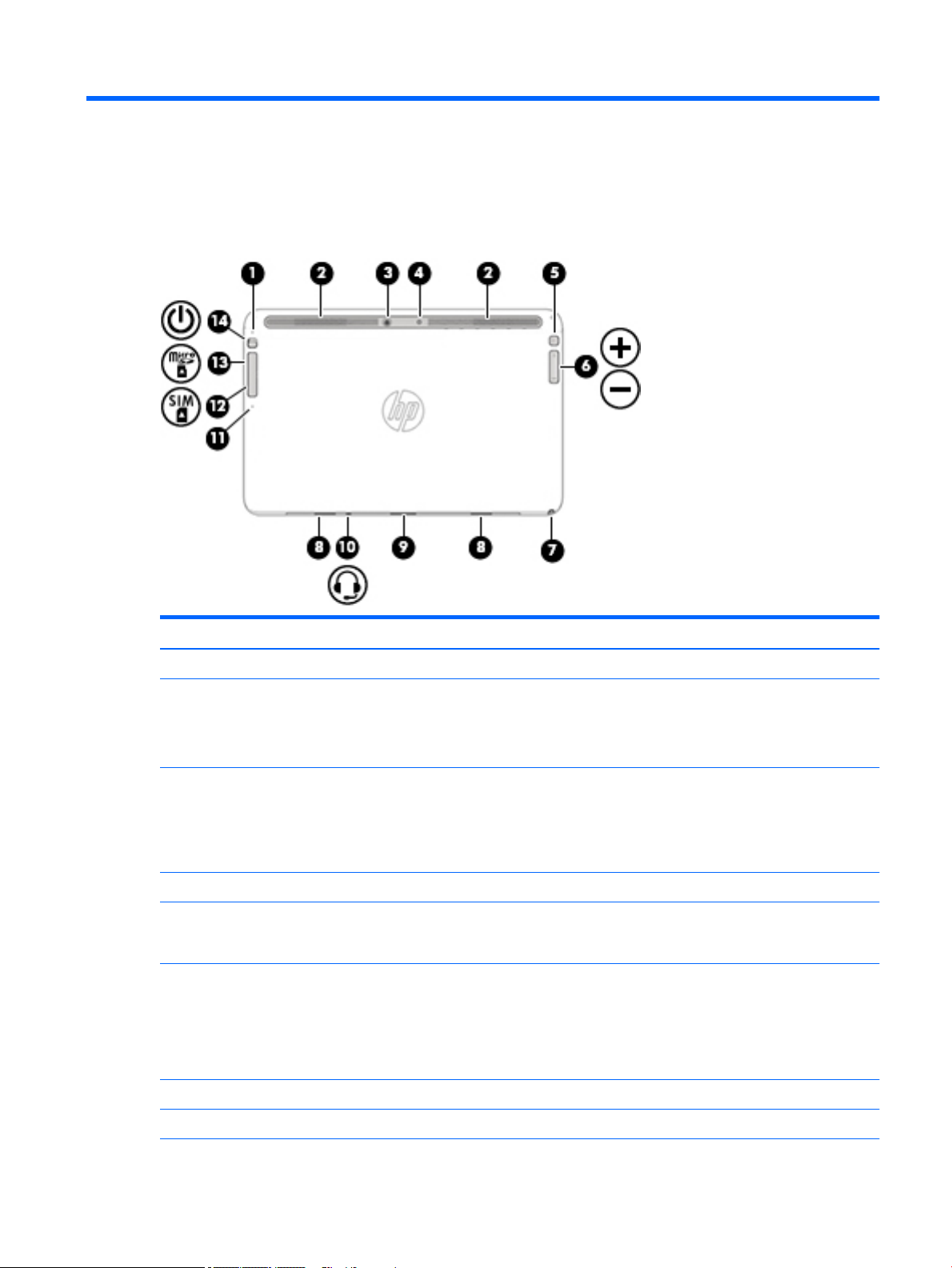
Item Component Description
(1) Internal microphone Record sound.
(2) Vents Enable airflow to cool internal components.
NOTE: The slate fan starts up automatically to cool internal
components and prevent overheating. It is normal for
the internal fan to cycle on and off during routine operation.
(3) Rear-facing webcam Records video and captures photographs. Some models
allow you to video conference and chat online using
streaming video.
For information on using the webcam, select Start > All
Programs > Communication and Chat > HP Webcam.
(4) Camera flash Provides light for rear-facing webcam photos.
(5) Rotate lock button When the slate is on, press the rotate lock button to lock
the autorotate feature of the display. To unlock
the autorotate feature, press the button again.
(6) Volume button Controls speaker volume on the slate.
●
To increase speaker volume, press the + edge of
the button.
●
To decrease speaker volume, press the – edge of
the button.
(7) Pen holder (select models only) Holds the digital pen.
(8) Alignment post connectors (2) Align and attach the slate to the keyboard.
Slate edge components 5
Page 14

Item Component Description
(9) Docking/adapter port Connects the slate to the keyboard, or as a slate only,
connects an optional adapter.
(10) Audio-out (headphone)/Audio-in (microphone) jack Connects optional powered stereo speakers, headphones,
earbuds, a headset, or a television audio cable. Also connects
an optional headset microphone. This jack does not support
optional microphone-only devices.
WARNING! To reduce the risk of personal injury, adjust
the volume before putting on headphones, earbuds, or a
headset. For additional safety information, see
the Regulatory, Safety, and Environmental Notices. To access
the user guides, select Start > Help and Support >
User Guides.
NOTE: When a device is connected to the jack, the slate
speakers are disabled.
NOTE: Be sure that the device cable has a 4-conductor
connector that supports both audio-out (headphone) and
audio-in (microphone).
(11) SIM/SD card release access A pinhole for use in ejecting the door covering the SIM and SD
card slots.
(12) SIM Card slot (select models only) A slot for a SIM card.
NOTE: This feature is available on select models only.
(13) Micro SD memory card reader Reads optional memory cards that store, manage, share, or
access information.
To insert a card:
Hold the card label-side up, with connectors facing the slot,
insert the card into the slot, and then push in on the card until
it is firmly seated.
To remove a card:
Press in on the card it until it pops out.
(14) Power button
6 Chapter 2 External component identification
●
When the slate is off, press the button to turn on
the slate.
●
When the slate is on, press the button briefly to initiate
Sleep.
●
When the slate is in the Sleep state, press the button
briefly to exit Sleep.
●
When the slate is in Hibernation, press the button
briefly to exit Hibernation.
CAUTION: Pressing and holding down the power button will
result in the loss of unsaved information.
If the slate has stopped responding and Windows shutdown
procedures are ineffective, press and hold the power button
for at least 15 seconds to turn off the slate.
Page 15

Item Component Description
NOTE: For select models, the Intel Rapid Start Technology
feature is enabled at the factory. Rapid Start Technology
allows your slate to resume quickly from inactivity.
To learn more about your power settings, see your power
options. From the Start screen, type power, select Power
and sleep settings, and then select Power and sleep from
the list of applications.
Slate edge components 7
Page 16
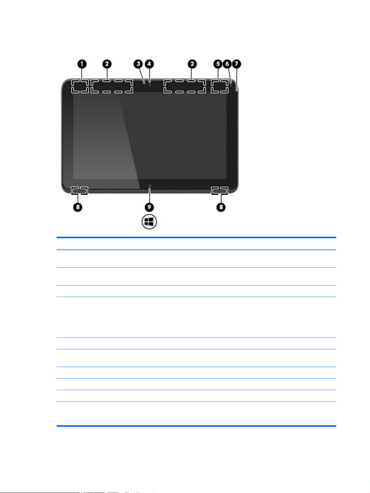
Slate display components
Item Component Description
(1) WLAN antenna* Sends and receives wireless signals to communicate
with WLANs.
(2) WWAN antennas (2)* Send and receive wireless signals to communicate
(3) Webcam light On: The webcam is in use.
(4) Front-facing webcam Records video and captures photographs. Some models
(5) WiGig antenna* Sends and receives wireless signals.
(6) Ambient light sensor Automatically adjusts the display brightness based on
(7) Internal microphone Record sound.
(8) Speakers (2) Produce sound.
(9) Windows button Displays the Windows Start menu.
*The antennas are not visible on the outside of the slate. For optimal transmission, keep the areas immediately around the antennas
free from obstructions. To see wireless regulatory notices, see the section of the Regulatory, Safety, and Environmental Notices that
applies to your country or region. To access the user guides, select Start > Help and Support > User Guides.
with WWANs.
allow you to video conference and chat online using
streaming video.
For information on using the webcam, select Start > All
Programs > Communication and Chat > HP WebCam.
the lighting conditions in your environment.
8 Chapter 2 External component identification
Page 17
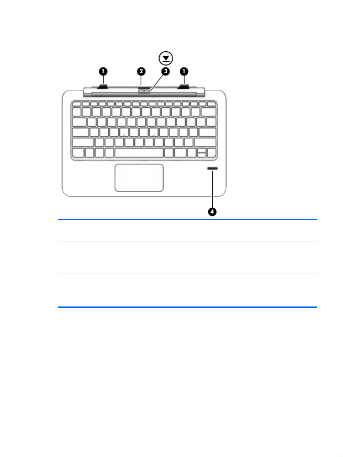
Keyboard base
Item Component Description
(1) Alignment posts (2) Align and attach the slate to the keyboard.
(2) Docking connector Connects the slate to the keyboard.
CAUTION: To prevent damage to the docking connector, do
not touch the connector when the slate is detached from
the keyboard.
(3) Release latch Releases the slate from the keyboard. To release the slate,
press the release latch.
(4) Fingerprint reader (select models only) Allows a fingerprint logon to Windows, instead of a
password logon.
Keyboard base 9
Page 18
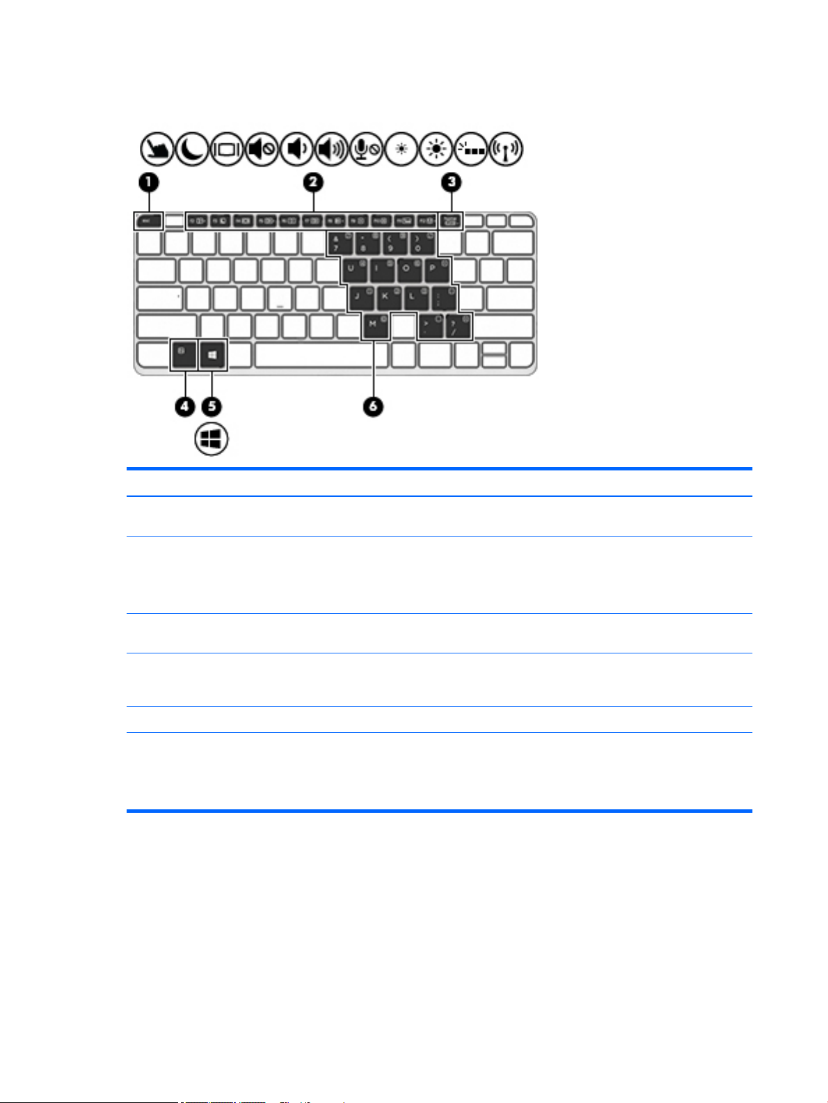
Keys
Item Component Description
(1) esc key Displays system information when pressed in combination
with the fn key.
(2) Function keys Execute frequently used system functions when pressed in
combination with the fn key.
NOTE: Function keys do not display or function from
the on-screen slate keyboard.
(3) num lock key Turns the embedded numeric keypad on and off when
pressed in combination with the fn key.
(4) fn key Executes frequently used system functions when pressed in
combination with a function key, the num lock key, or
the esc key.
(5) Windows key Displays the Windows Start menu.
(6) Embedded numeric keypad When num lock has been enabled, it can be used like an
external numeric keypad.
Each key on the keypad performs the function indicated by
the icon in the upper-right corner of the key.
10 Chapter 2 External component identification
Page 19
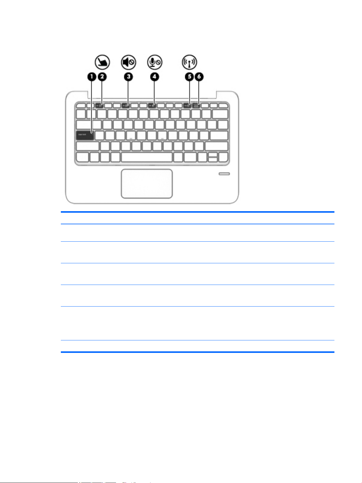
Lights
Item Component Description
(1) Caps lock light On: Caps lock is on, which switches the keys to all
capital letters.
(2) TouchPad light
(3) Mute light
(4) Microphone mute light
(5) Wireless light On: An integrated wireless device, such as a wireless local
(6) Num lock light On: Num lock is on.
●
On: The TouchPad is off.
●
Off: The TouchPad is on.
●
Amber: Slate sound is off.
●
Off: Slate sound is on.
●
Amber: microphone sound is off.
●
Off: microphone sound is on.
area network (WLAN) device and/or a Bluetooth device, is on.
NOTE: On some models, the wireless light is amber when
all wireless devices are off.
Lights 11
Page 20
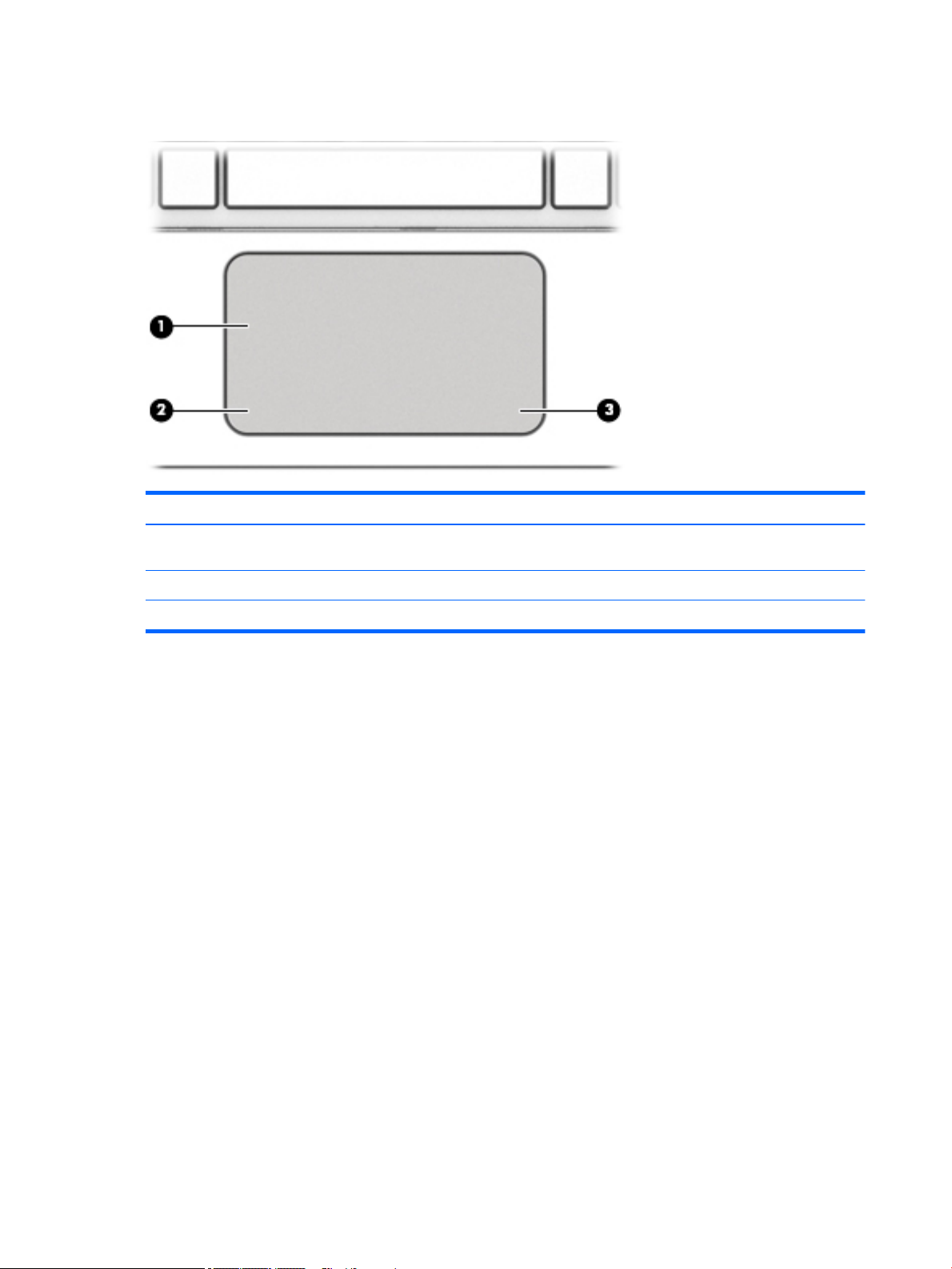
TouchPad
Item Component Description
(1) TouchPad zone Moves the pointer and selects or activates items on
the screen.
(2) Left TouchPad button Functions like the left button on an external mouse.
(3) Right TouchPad button Functions like the right button on an external mouse.
12 Chapter 2 External component identification
Page 21
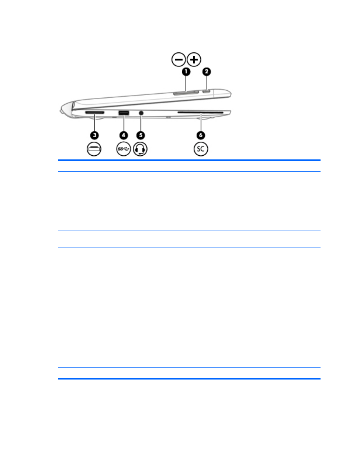
Left side
Item Component Description
(1) Volume button Controls speaker volume on the slate.
●
To increase speaker volume, press the + edge of
the button.
●
To decrease speaker volume, press the – edge of
the button.
(2) LCD rotation lock button Locks orientation of the display, preventing
automatic rotation.
(3) Docking/adapter port Connects the slate to the keyboard, or as a slate only,
connects an optional adapter.
(4) USB 3.0 port Connects an optional USB device, such as a keyboard, mouse,
external drive, printer, scanner or USB hub.
(5) Audio-out (headphone)/Audio-in (microphone) jack Connects optional powered stereo speakers, headphones,
earbuds, a headset, or a television audio cable. Also connects
an optional headset microphone. This jack does not support
optional microphone-only devices.
WARNING! To reduce the risk of personal injury, adjust
the volume before putting on headphones, earbuds, or a
headset. For additional safety information, see
the Regulatory, Safety, and Environmental Notices. To access
the user guides, select Start > Help and Support >
User Guides.
NOTE: When a device is connected to the jack, the slate
speakers are disabled.
NOTE: Be sure that the device cable has a 4-conductor
connector that supports both audio-out (headphone) and
audio-in (microphone).
(6) Smart card reader Supports optional Smart cards.
Left side 13
Page 22
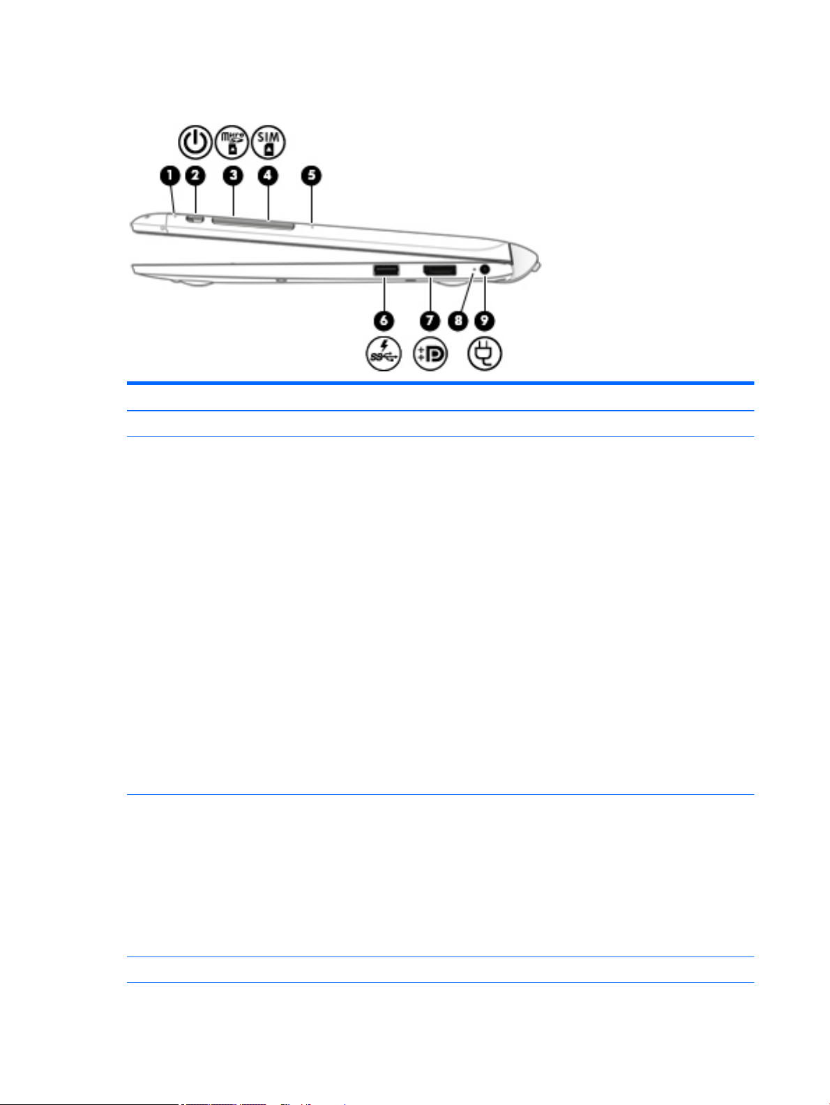
Right side
Item Component Description
(1) Internal microphone Records sound.
(2) Power button
(3) Micro SD memory card reader Reads optional memory cards that store, manage, share, or
●
When the slate is off, press the button to turn on
the slate.
●
When the slate is on, press the button briefly to initiate
Sleep.
●
When the slate is in the Sleep state, press the button
briefly to exit Sleep.
●
When the slate is in Hibernation, press the button
briefly to exit Hibernation.
CAUTION: Pressing and holding down the power button will
result in the loss of unsaved information.
If the slate has stopped responding and Windows shutdown
procedures are ineffective, press and hold the power button
for at least 5 seconds to turn off the slate.
NOTE: For select models, the Intel Rapid Start Technology
feature is enabled at the factory. Rapid Start Technology
allows your slate to resume quickly from inactivity.
To learn more about your power settings, see your power
options. From the Start screen, type power, select Power
and sleep settings, and then select Power and sleep from
the list of applications.
access information.
To insert a card:
Hold the card label-side up, with connectors facing the slot,
insert the card into the slot, and then push in on the card until
it is firmly seated.
To remove a card:
Press in on the card it until it pops out.
(4) SIM Card slot (select models only) A slot for a SIM card.
14 Chapter 2 External component identification
Page 23

Item Component Description
(5) SIM/SD card release access A pinhole for use in ejecting the door covering the SIM and SD
card slots.
(6) USB 3.0 charging (powered) port Connects an optional USB device, such as a keyboard, mouse,
external drive, printer, scanner or USB hub. Standard USB
ports will not charge all USB devices or will charge using a
low current. Some USB devices require power and require you
to use a powered port.
NOTE: USB charging ports can also charge select models of
cell phones and MP3 players, even when the slate is off.
(7) Dual-Mode DisplayPort Connects an optional digital display device, such as a high-
performance monitor or projector.
(8) AC adapter/battery light
(9) Power connector Connects an AC adapter.
*The antennas are not visible on the outside of the slate. For optimal transmission, keep the areas immediately around the antennas
free from obstructions. To see wireless regulatory notices, see the section of the Regulatory, Safety, and Environmental Notices that
applies to your country or region. To access the user guides, select Start > Help and Support > User Guides.
●
White: The slate is connected to external power and
the battery is charged from 90 to 99 percent.
●
Amber: The slate is connected to external power and
the battery is charged from 0 to 90 percent.
●
Blinking amber: A battery that is the only available
power source has reached a low battery level. When
the battery reaches a critical battery level, the battery
light begins blinking rapidly.
●
Off: The battery is fully charged.
Right side 15
Page 24
3 Illustrated parts catalog
NOTE: HP continually improves and changes product parts. For complete and current information on
supported parts for your slate, go to http://partsurfer.hp.com, select your country or region, and then follow
the on-screen instructions.
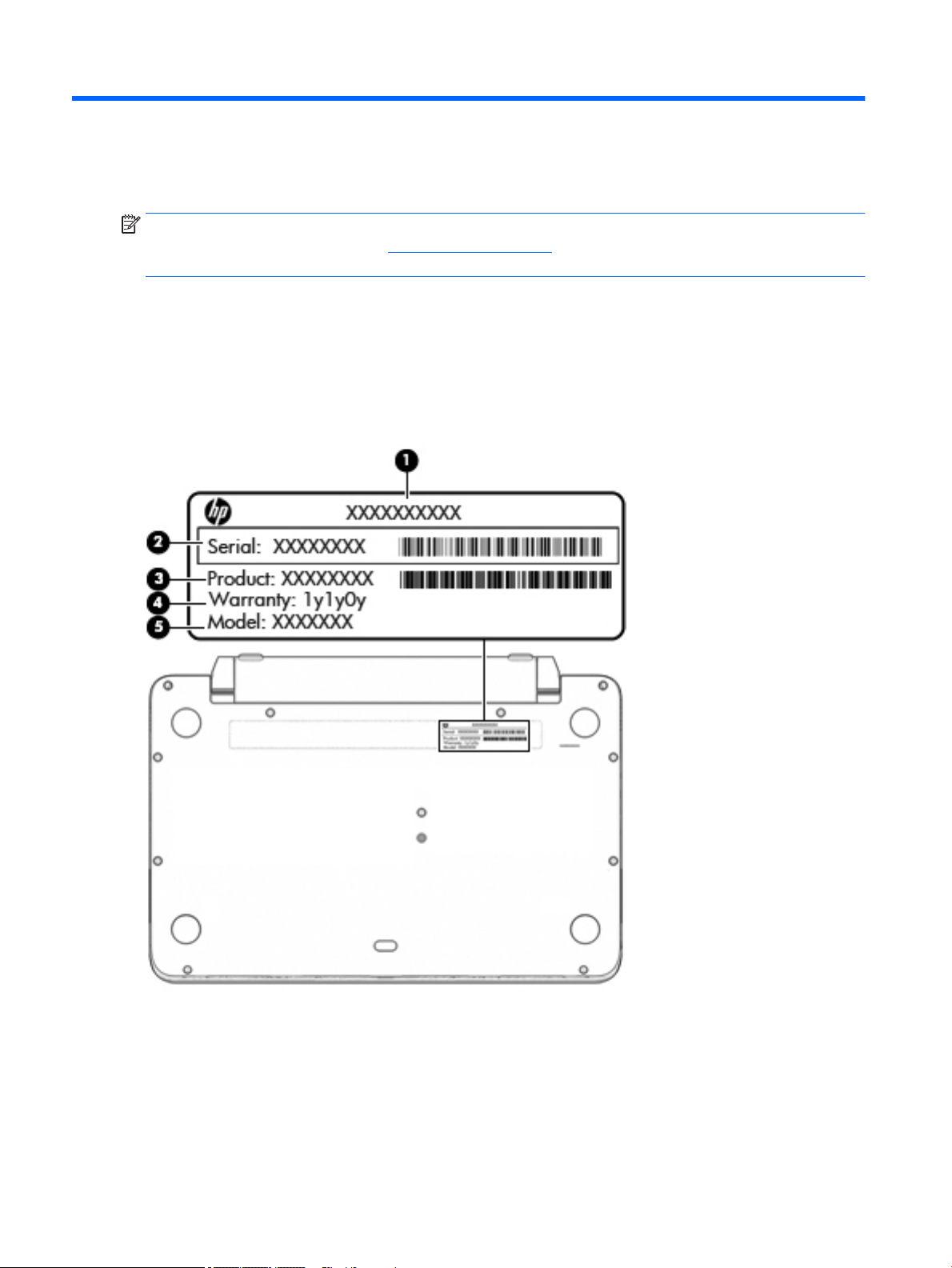
Locating the product name, serial number, product number, warranty information, and model name
The product name (1), serial number (2), product number (3), warranty information (4), and model name (5)
are located on the bottom of the slate. You may need this information when you travel internationally or
when you contact support.
16 Chapter 3 Illustrated parts catalog
Page 25
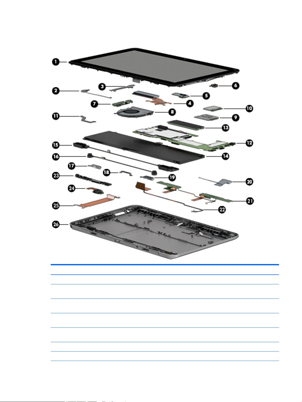
Slate major components
Item Component Spare part number
(1) 11.6-in, TouchScreen display panel assembly:
FHD, BV, (1920×1080), IPS, 50% CG, typical brightness 400 nits, eDP 1.3, ultra-slim
with digitizer
FHD, BV, (1920×1080), IPS, 50% CG, typical brightness 400 nits, eDP 1.3, ultra-slim
without digitizer
HD, BV, (1366×768), IPS, 50% CG, typical brightness 400 nits, eDP 1.2, ultra-slim
with digitizer
HD, BV, (1366×768), IPS, 50% CG, typical brightness 400 nits, eDP 1.2, ultra-slim
without digitizer
Speaker grille (not illustrated; 2 pieces, includes double-sided adhesive) 793734-001
(2) RTC battery (includes cable and double-sided adhesive) 793723-001
793736-001
804352-001
793737-001
804351-001
Slate major components 17
Page 26

Item Component Spare part number
(3) Volume button board bracket: Included in the Slate Bracket Kit, spare part number 793728-001.
(4) Heat sink (includes replacement thermal material) 793726-001
(5) Front-facing webcam (includes double-sided adhesive): Included in the Webcam Kit, spare
part number 793724-001.
NOTE: The front-facing webcam spare part kit does not include the front-facing webcam
cable. The front-facing webcam cable is included in the Slate Cable Kit, spare part number
793721-001.
(6) Rear-facing webcam: Included in the Webcam Kit, spare part number 793724-001.
NOTE: The rear-facing webcam spare part kit does not include the rear-facing webcam
cable. The rear-facing webcam cable is included in the Slate Cable Kit, spare part number
793721-001.
(7) Volume button board
NOTE: The volume button board spare part kit does not include the volume button board
cable. The volume button board cable is included in the Slate Cable Kit, spare part number
793721-001.
(8) Fan (includes cable) 793735-001
(9) WWAN module:
HP hs3110 HSPA+ Mobile Broadband 748599-005
HP lt4112 LTE/HSPA+ 4G Mobile Broadband 740011-005
HP lt4225 LTE/EV-DO Gobi 4G Module 736676-005
HP lt4226 LTE/HSPA+ Gobi 4G Module 736675-005
(10) WLAN module:
750549-005
804344-001
793733-001
Intel Tri Band Wireless-AC 17265 802.11a/b/g/n/ac 2×2 and Bluetooth 4.0 + WiGig
Combo Adapter
Intel Dual Band Wireless-AC 7265 802.11a/b/g/n/ac 2×2 WiFi and Bluetooth 4.0
Combo Adapter
Intel Dual Band Wireless-AN 7265 802.11a/b/g/n 2×2 and Bluetooth 4.0 Combo Adapter 756748-005
(11) Display panel cable (includes double-sided adhesive) 804344-001
(12) System board (includes a graphics subsystem with UMA memory and replacement thermal material):
Equipped with an Intel Core i7 M-5Y71 processor, 8.0-GB of system memory,
and the Windows 8 Professional operating system
Equipped with an Intel Core i7 M-5Y71 processor, 8.0-GB of system memory,
and the Windows 8 Standard operating system
Equipped with an Intel Core i7 M-5Y71 processor, 8.0-GB of system memory, and a non-
Windows 8 operating system
Equipped with an Intel Core i7 M-5Y71 processor, 4.0-GB of system memory,
and the Windows 8 Professional operating system
Equipped with an Intel Core i7 M-5Y71 processor, 4.0-GB of system memory,
and the Windows 8 Standard operating system
Equipped with an Intel Core i7 M-5Y71 processor, 4.0-GB of system memory, and a non-
Windows 8 operating system
806724-005
756749-005
805071-601
805071-501
805071-001
805072-601
805072-501
805072-001
18 Chapter 3 Illustrated parts catalog
Page 27

Item Component Spare part number
Equipped with an Intel Core i5 M-5Y51 processor, 8.0-GB of system memory,
and the Windows 8 Professional operating system
Equipped with an Intel Core i5 M-5Y51 processor, 8.0-GB of system memory,
and the Windows 8 Standard operating system
Equipped with an Intel Core i5 M-5Y51 processor, 8.0-GB of system memory, and a non-
Windows 8 operating system
Equipped with an Intel Core i5 M-5Y51 processor, 4.0-GB of system memory,
and the Windows 8 Professional operating system
Equipped with an Intel Core i5 M-5Y51 processor, 4.0-GB of system memory,
and the Windows 8 Standard operating system
Equipped with an Intel Core i5 M-5Y51 processor, 4.0-GB of system memory, and a non-
Windows 8 operating system
Equipped with an Intel Core i3 M-5Y10c processor, 4.0-GB of system memory,
and the Windows 8 Professional operating system
Equipped with an Intel Core i3 M-5Y10c processor, 4.0-GB of system memory,
and the Windows 8 Standard operating system
Equipped with an Intel Core i3 M-5Y10c processor, 4.0-GB of system memory, and a non-
Windows 8 operating system
(13) Solid-state drive:
512-GB, M2, SATA-3 solid-state drive 811391-001
805070-601
805070-501
805070-001
805069-601
805069-501
805069-001
805068-601
805068-501
805068-001
256-GB, M2, SATA-3 793709-001
256-GB, M2, SATA-3 solid-state drive supporting TLC 811793-001
256-GB, M2, SATA-3, SED solid-state drive supporting Opal 2 810987-001
180-GB, M2, SATA-3 811389-001
180-GB, M2, SATA-3, SED solid-state drive supporting Opal 2 811390-001
128-GB, M2, SATA-3 793708-001
128-GB, M2, SATA-3 solid-state drive supporting TLC 811392-001
(14) Battery, 2-cell, 33-WHr, 4.56-AHr, LI (includes cable) 750549-005
(15) Speakers (includes left and right speakers and cables) 793729-001
(16) Vibrator module (includes left and right vibrator modules and cables) 793730-001
(17) Alignment bracket, left: Included in the Slate Bracket Kit, spare part number 793728-001.
(18) Docking connector bracket: Included in the Slate Bracket Kit, spare part number 793728-001.
(19) Alignment bracket, right: Included in the Slate Bracket Kit, spare part number 793728-001.
Antenna Kit, includes:
(20) WiGig antenna cable and transceiver (for use only on slate models equipped with
WiGig capability)
(21) WWAN main and auxiliary cables and transceivers
805066-001
(22) WLAN antenna cable and transceiver
For use in African, European, and Middle Eastern countries and regions 805065-001
Slate major components 19
Page 28

Item Component Spare part number
For use in Japan 806251-001
For use in North America 805067-001
(23) Docking connector board
NOTE: The docking connector board spare part kit does not include the docking connector
board cable. The docking connector board cable is included in the Slate Cable Kit, spare part
number 793721-001.
(24) Audio jack board (includes cable) 793732-001
(25) Docking connector board cable: Included in the Slate Cable Kit, spare part number 793721-001.
(26) Back cover 793725-001
793731-001
20 Chapter 3 Illustrated parts catalog
Page 29
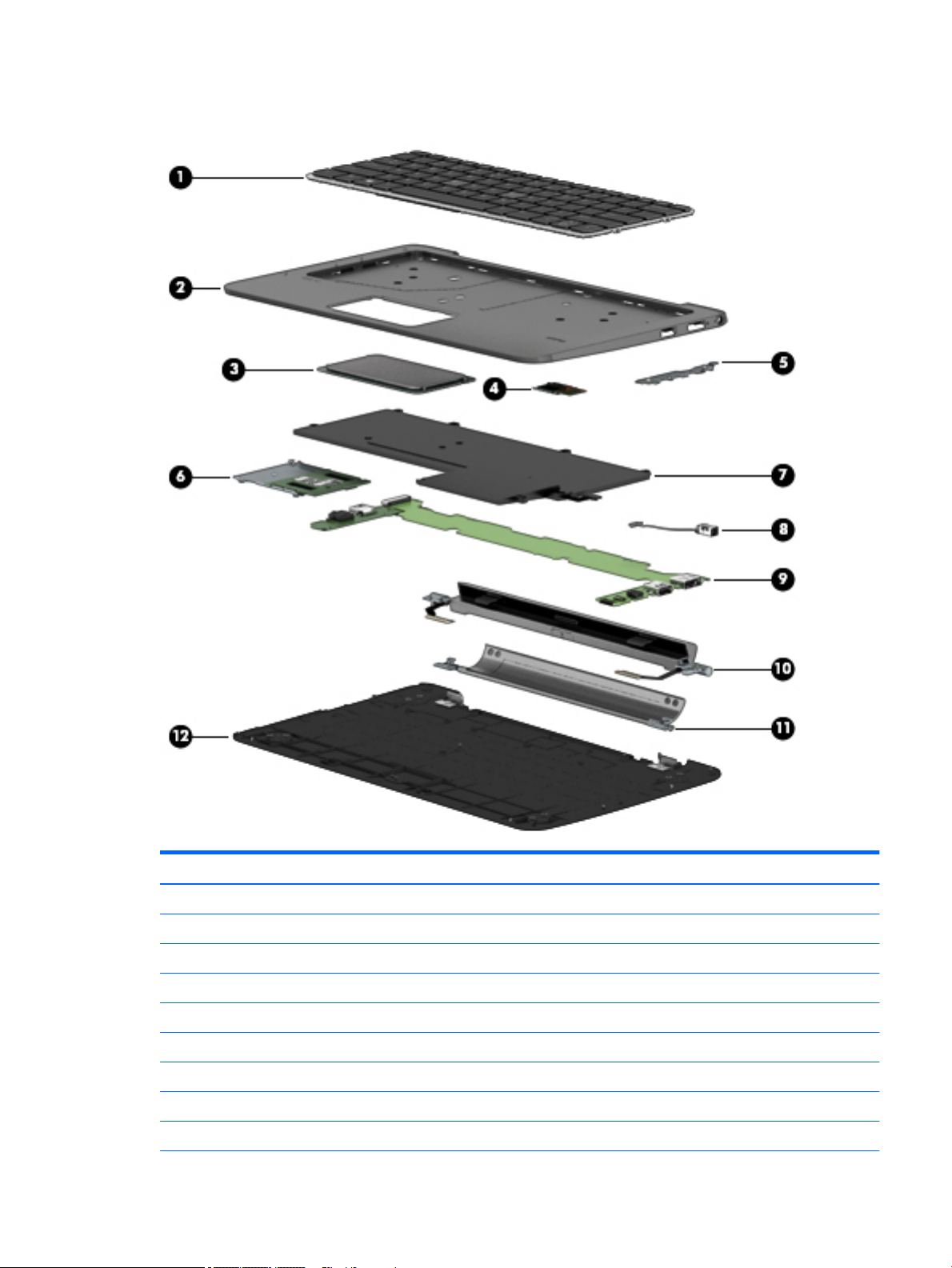
Keyboard base
Item Description Spare part number
(1) Keyboard (includes keyboard cable and keyboard backlight cable):
For use in Belgium 793738-A41
For use in Brazil 793738-201
For use in Bulgaria 793738-261
For use in Canada 793738-DB1
For use in the Czech Republic and Slovakia 793738-FL1
For use in Denmark 793738-081
For use in France 793738-051
For use in Germany 793738-041
Keyboard base 21
Page 30

Item Description Spare part number
For use in Greece 793738-151
For use in Hungary 793738-211
For use in Iceland 793738-DD1
For use in India 793738-D61
For use in Israel 793738-BB1
For use in Italy 793738-061
For use in Japan 793738-291
For use in Latin America 793738-161
For use in the Netherlands 793738-B31
For use in North Africa 793738-FP1
For use in Portugal 793738-131
For use in Romania 793738-271
For use in Russia 793738-251
For use in Saudi Arabia 793738-171
For use in Slovenia 793738-BA1
For use in South Korea 793738-AD1
For use in Spain 793738-071
For use in Sweden and Finland 793738-B71
For use in Switzerland 793738-111
For use in Taiwan 793738-AB1
For use in Thailand 793738-281
For use in Turkey 793738-141
For use in the United Kingdom and Singapore 793738-031
For use in the United States 793738-001
(2) Top cover 793718-001
(3) TouchPad (includes cable) 793720-001
(4) Fingerprint reader board
NOTE: The fingerprint reader board spare part kit does not include the fingerprint reader
board cable. The fingerprint reader board cable is included in the Keyboard Base Cable Kit,
spare part number 793721-001.
(5) Connector board (includes USB port and DisplayPort)
NOTE: The connector board spare part kit does not include the connector board cable.
The connector board cable is included in the Keyboard Base Cable Kit, spare part number
793721-001.
793713-001
804350-001
(6) Smart card reader board 793711-001
22 Chapter 3 Illustrated parts catalog
Page 31

Item Description Spare part number
NOTE: The smart card reader board spare part kit does not include the smart card reader
board cable. The smart card reader board cable is included in the Keyboard Base Cable Kit,
spare part number 793721-001.
(7) Battery, 6-cell, 21-WHr, 0.95-AHr, LI (includes cable) 750550-005
(8) Power connector cable 793714-001
(9) Keyboard base system board (includes docking/adapter port, USB port, and audio jack) 806252-001
(10) Hinge assembly (includes left and right cables) 793717-001
(11) Kickstand (includes rubber feet) 793715-001
Kickstand Hinge Kit (not illustrated) 793716-001
(12) Bottom cover 793710-001
Rubber Kit (not illustrated, includes bottom cover rubber feet) 804348-001
Miscellaneous parts
Component Spare part number
AC adapter:
65-W HP Smart adapter (non-PFC, 3-wire) 693716-001
45-W HP Smart adapter (non-PFC, RC, 3-wire) 742436-001
Bracket Kit:
For use on the keyboard base, includes:
●
Connector board cable
●
Fingerprint reader board cable
●
Smart card reader board cable
For use on the slate, includes:
●
Alignment guide left bracket
●
Alignment guide right bracket
●
Docking connector board bracket
●
Volume button board bracket
Cable Kit:
For use on the keyboard base, includes:
●
Connector board cable
●
Fingerprint reader board cable
●
Smart card reader board cable
793712-001
793728-001
793719-001
For use on the slate, includes:
●
Digitizer board cable
●
Docking connector board cable
793721-001
Miscellaneous parts 23
Page 32

Component Spare part number
●
Front-facing webcam cable
●
Rear-facing webcam cable
●
TouchScreen cable
●
Volume button board cable
Digitizer pen 804346-001
Travel keyboard:
For use in Belgium 800577-A41
For use in Brazil 800577-201
For use in Bulgaria 800577-261
For use in the Czech Republic and Slovakia 800577-FL1
For use in Denmark 800577-081
For use in France 800577-051
For use in Germany 800577-041
For use in Greece 800577-151
For use in Hungary 800577-211
For use in Iceland 800577-DD1
For use in India 800577-D61
For use in Israel 800577-BB1
For use in Italy 800577-061
For use in Japan 800577-291
For use in Latin America 800577-161
For use in the Netherlands 800577-B31
For use in North Africa 800577-FP1
For use in Norway 800577-091
For use in Portugal 800577-131
For use in Romania 800577-271
For use in Russia 800577-251
For use in Saudi Arabia 800577-171
For use in Slovenia 800577-BA1
For use in South Korea 800577-AD1
For use in Spain 800577-071
For use in Sweden and Finland 800577-B71
For use in Switzerland 800577-111
For use in Taiwan 800577-AB1
24 Chapter 3 Illustrated parts catalog
Page 33

Component Spare part number
For use in Thailand 800577-281
For use in Turkey 800577-141
For use in the United Kingdom and Singapore 800577-031
For use in the United States 800577-001
Plastics Kit for use on the slate, includes:
●
Power button actuator
●
Rotate lock button actuator
●
SD card/SIM cover
●
Volume button actuator
Power cord, 3-pin, black, 1.83-m:
For use in Argentina 490371-D01
For use in Australia 490371-011
For use in Brazil 490371-202
For use in Denmark 490371-081
For use in Europe 490371-021
For use in India 490371-D61
For use in Israel 490371-BB1
For use in Italy 490371-061
For use in Japan 490371-291
For use in North America 490371-001
For use in the People's Republic of China 490371-AA1
804347-001
For use in South Africa 490371-AR1
For use in South Korea 490371-AD1
For use in Switzerland 490371-111
For use in Taiwan 490371-AB1
For use in Thailand 490371-201
For use in the United Kingdom and Singapore 490371-031
Power cord, 3-pin, black, 1.83-m:
For use in Argentina 755530-D01
For use in Australia 755530-011
For use in Brazil 755530-202
For use in Denmark 755530-081
For use in Europe 755530-021
For use in India 755530-D61
Miscellaneous parts 25
Page 34

Component Spare part number
For use in Israel 755530-BB1
For use in Italy 755530-061
For use in Japan 755530-291
For use in North America 755530-001
For use in the People's Republic of China 755530-AA1
For use in South Africa 755530-AR1
For use in South Korea 755530-AD1
For use in Switzerland 755530-111
For use in Taiwan 755530-AB1
For use in Thailand 755530-201
For use in the United Kingdom and Singapore 755530-031
Power cord, 2-pin, black, 1.00-m, for use in Japan 762689-291
Screw Kit:
For use on the keyboard base 804349-001
For use on the slate 793727-001
26 Chapter 3 Illustrated parts catalog
Page 35

4 Removal and replacement preliminary
requirements
Tools required
You will need the following tools to complete the removal and replacement procedures:
●
Flat-bladed screw driver
●
Magnetic screw driver
●
Phillips P0 screw driver
Service considerations
The following sections include some of the considerations that you must keep in mind during disassembly
and assembly procedures.
NOTE: As you remove each subassembly from the slate, place the subassembly (and all accompanying
screws) away from the work area to prevent damage.
Plastic parts
CAUTION: Using excessive force during disassembly and reassembly can damage plastic parts. Use care
when handling the plastic parts. Apply pressure only at the points designated in the
maintenance instructions.
Cables and connectors
CAUTION: When servicing the slate, be sure that cables are placed in their proper locations during the
reassembly process. Improper cable placement can damage the slate.
Cables must be handled with extreme care to avoid damage. Apply only the tension required to unseat or
seat the cables during removal and insertion. Handle cables by the connector whenever possible. In all cases,
avoid bending, twisting, or tearing cables. Be sure that cables are routed in such a way that they cannot be
caught or snagged by parts being removed or replaced. Handle flex cables with extreme care; these cables
tear easily.
Grounding guidelines
Electrostatic discharge damage
Electronic components are sensitive to electrostatic discharge (ESD). Circuitry design and structure
determine the degree of sensitivity. Networks built into many integrated circuits provide some protection,
but in many cases, ESD contains enough power to alter device parameters or melt silicon junctions.
A discharge of static electricity from a finger or other conductor can destroy static-sensitive devices or
microcircuitry. Even if the spark is neither felt nor heard, damage may have occurred.
Tools required 27
Page 36

An electronic device exposed to ESD may not be affected at all and can work perfectly throughout a normal
cycle. Or the device may function normally for a while, then degrade in the internal layers, reducing its life
expectancy.
CAUTION: To prevent damage to the slate when you are removing or installing internal components,
observe these precautions:
Keep components in their electrostatic-safe containers until you are ready to install them.
Before touching an electronic component, discharge static electricity by using the guidelines described in this
section.
Avoid touching pins, leads, and circuitry. Handle electronic components as little as possible.
If you remove a component, place it in an electrostatic-safe container.
The following table shows how humidity affects the electrostatic voltage levels generated by
different activities.
CAUTION: A product can be degraded by as little as 700 V.
Typical electrostatic voltage levels
Relative humidity
Event 10% 40% 55%
Walking across carpet 35,000 V 15,000 V 7,500 V
Walking across vinyl floor 12,000 V 5,000 V 3,000 V
Motions of bench worker 6,000 V 800 V 400 V
Removing DIPS from plastic tube 2,000 V 700 V 400 V
Removing DIPS from vinyl tray 11,500 V 4,000 V 2,000 V
Removing DIPS from Styrofoam 14,500 V 5,000 V 3,500 V
Removing bubble pack from PCB 26,500 V 20,000 V 7,000 V
Packing PCBs in foam-lined box 21,000 V 11,000 V 5,000 V
28 Chapter 4 Removal and replacement preliminary requirements
Page 37

Packaging and transporting guidelines
Follow these grounding guidelines when packaging and transporting equipment:
●
To avoid hand contact, transport products in static-safe tubes, bags, or boxes.
●
Protect ESD-sensitive parts and assemblies with conductive or approved containers or packaging.
●
Keep ESD-sensitive parts in their containers until the parts arrive at static-free workstations.
●
Place items on a grounded surface before removing items from their containers.
●
Always be properly grounded when touching a component or assembly.
●
Store reusable ESD-sensitive parts from assemblies in protective packaging or nonconductive foam.
●
Use transporters and conveyors made of antistatic belts and roller bushings. Be sure that mechanized
equipment used for moving materials is wired to ground and that proper materials are selected to avoid
static charging. When grounding is not possible, use an ionizer to dissipate electric charges.
Workstation guidelines
Follow these grounding workstation guidelines:
●
Cover the workstation with approved static-shielding material.
●
Use a wrist strap connected to a properly grounded work surface and use properly grounded tools and
equipment.
●
Use conductive field service tools, such as cutters, screw drivers, and vacuums.
●
When fixtures must directly contact dissipative surfaces, use fixtures made only of staticsafe materials.
●
Keep the work area free of nonconductive materials, such as ordinary plastic assembly aids
and Styrofoam.
●
Handle ESD-sensitive components, parts, and assemblies by the case or PCM laminate. Handle these
items only at static-free workstations.
●
Avoid contact with pins, leads, or circuitry.
●
Turn off power and input signals before inserting or removing connectors or test equipment.
Grounding guidelines 29
Page 38

Equipment guidelines
Grounding equipment must include either a wrist strap or a foot strap at a grounded workstation.
●
When seated, wear a wrist strap connected to a grounded system. Wrist straps are flexible straps with a
minimum of one megohm ±10% resistance in the ground cords. To provide proper ground, wear a strap
snugly against the skin at all times. On grounded mats with banana-plug connectors, use alligator clips
to connect a wrist strap.
●
When standing, use foot straps and a grounded floor mat. Foot straps (heel, toe, or boot straps) can be
used at standing workstations and are compatible with most types of shoes or boots. On conductive
floors or dissipative floor mats, use foot straps on both feet with a minimum of one megohm resistance
between the operator and ground. To be effective, the conductive must be worn in contact with the
skin.
The following grounding equipment is recommended to prevent electrostatic damage:
●
Antistatic tape
●
Antistatic smocks, aprons, and sleeve protectors
●
Conductive bins and other assembly or soldering aids
●
Nonconductive foam
●
Conductive slateop workstations with ground cords of one megohm resistance
●
Static-dissipative tables or floor mats with hard ties to the ground
●
Field service kits
●
Static awareness labels
●
Material-handling packages
●
Nonconductive plastic bags, tubes, or boxes
●
Metal tote boxes
●
Electrostatic voltage levels and protective materials
The following table lists the shielding protection provided by antistatic bags and floor mats.
Material Use Voltage protection level
Antistatic plastics Bags 1,500 V
Carbon-loaded plastic Floor mats 7,500 V
Metallized laminate Floor mats 5,000 V
30 Chapter 4 Removal and replacement preliminary requirements
Page 39

5 Removal and replacement procedures –
slate
NOTE: This chapter provides removal and replacement procedures for Authorized Service Provider only
components. Components described in this chapter should only be accessed by an authorized service
provider. Accessing these components can damage the slate or void the warranty.
There are as many as 45 screws that must be removed, replaced, and/or loosened when servicing the slate.
Make special note of each screw size and location during removal and replacement.
NOTE: HP continually improves and changes product parts. For complete and current information on
supported parts for your slate, go to http://partsurfer.hp.com, select your country or region, and then follow
the on-screen instructions.
Unlocking the device and disabling Always On Remote Management (select HP devices only)
HP Touchpoint Manager (HPTM) is a complete cloud-based solution for managing devices. For select HP
devices with the Windows operating system, the Always On Remote Management (AORM) feature is
automatically activated when HP Touchpoint Manager software is installed.
AORM can perform a secure BIOS level lock and can also securely erase internal drives (except for encrypted
self-encrypting drives). The HP Touchpoint Manager website (http://www.hptouchpointmanager.com)
provides access to the AORM lock feature. The device must be unlocked using an authorized PIN from
the same website before you can access HP Slate Setup and start the Windows operating system.
IMPORTANT: A service agent cannot retrieve the PIN from the HP Touchpoint Manager website. If a locked
device is returned for service, the agent must contact the customer to obtain the PIN to unlock the device. If a
PIN is not available, the entire system board must be replaced.
Before returning the device for service, be sure to unlock the device using the PIN from the HP Touchpoint
Manager website (http://www.hptouchpointmanager.com), and also disable the AORM feature in HP Slate
Setup.
To disable AORM:
1. Access HP Slate Setup (F10).
a. Turn on or restart the device, and then press esc while the “Press the ESC key for Startup Menu”
message is displayed at the bottom of the screen.
b. Press f10 to enter Slate Setup.
NOTE: If the BIOS is protected with an Administrator password, enter the password.
2. Select Advanced, and then select HP Touchpoint Manager Options.
3. Clear the Allow Activation check box.
4. Select Save changes and exit.
Unlocking the device and disabling Always On Remote Management (select HP devices only) 31
Page 40

Display panel assembly
Description Spare part number
11.6-in, TouchScreen, FHD, BV, (1920×1080), IPS, 50% CG, typical brightness 400 nits, eDP 1.3, ultraslim with digitizer display panel assembly
11.6-in, TouchScreen, FHD, BV, (1920×1080), IPS, 50% CG, typical brightness 400 nits, eDP 1.3, ultraslim without digitizer display panel assembly
11.6-in, TouchScreen, HD, BV, (1366×768), IPS, 50% CG, typical brightness 400 nits, eDP 1.2, ultra-slim
with digitizer display panel assembly
11.6-in, TouchScreen, HD, BV, (1366×768), IPS, 50% CG, typical brightness 400 nits, eDP 1.2, ultra-slim
without digitizer display panel assembly
Back cover 793725-001
793736-001
804352-001
793737-001
804351-001
Before removing the disassembling the slate, follow these steps:
1. Turn off the slate. If you are unsure whether the slate is off or in Hibernation, turn the slate on, and then
shut it down through the operating system.
2. Disconnect the power from the slate by unplugging the power cord from the slate.
3. Disconnect all external devices from the slate.
Remove the display panel assembly:
1. Place the slate on a flat work surface with the docking connector toward you.
2. Remove the speaker grille (1) that covers the display panel screws.
The speaker grille is available using spare part number 793734-001.
3. Remove the six Phillips PM1.5×8.3 screws (2) and the three Phillips PM1.5×3.5 screws (3) that secure
the display panel assembly to the bottom cover.
CAUTION: Do not completely separate the display panel assembly from the bottom cover in the next
step. There are 2 ribbon cables connecting the display panel assembly to the system board that can be
damaged if too much separation is achieved.
32 Chapter 5 Removal and replacement procedures – slate
Page 41

4. Lift the bottom edge (4) of the display panel assembly until it separates from the bottom cover.
5. Release the zero insertion force (ZIF) connector (1) to which the TouchScreen board cable is attached,
and then disconnect the TouchScreen board cable from the system board.
6. Release the adhesive strip (2) that secures the display panel cable connector to the system board.
7. Disconnect the display panel cable (3) from the system board.
8. Release the ZIF connector (4) to which the digitizer board cable is attached, and then disconnect
the digitizer board cable from the system board.
Display panel assembly 33
Page 42

9. Remove the display panel assembly (5).
CAUTION: Before turning the display panel upside down, make sure the work surface is clear of tools,
screws, and any other foreign objects. Failure to follow this caution can result in damage to
the display panel assembly.
10. If it is necessary to replace the display panel cable:
a. Turn the display panel assembly upside down with the docking connector toward you.
b. Release the adhesive strip (1) that secures the display panel cable connector to
the display panel assembly.
c. Disconnect the display panel cable (2) from the display panel.
34 Chapter 5 Removal and replacement procedures – slate
Page 43

d. Remove the display panel cable (3).
The display panel cable is available using spare part number 804344-001.
Reverse this procedure to reassemble and install the display panel assembly.
Display panel assembly 35
Page 44

Battery
Description Spare part number
Battery, 2-cell, 33-WHr, 4.56-AHr, Li-ion (includes cable) 750549-005
Before removing the battery, follow these steps:
1. Shut down the slate. If you are unsure whether the slate is off or in Hibernation, turn the slate on, and
2. Disconnect all external devices connected to the slate.
3. Disconnect the power from the slate by first unplugging the power cord from the AC outlet and then
4. Remove the display panel assembly (see Display panel assembly on page 32).
WARNING! To reduce potential safety issues, use only the battery provided with the slate, a replacement
battery provided by HP, or a compatible battery purchased from HP.
CAUTION: Removing a battery that is the sole power source for the slate can cause loss of information.
To prevent loss of information, save your work or shut down the slate through Windows before removing
the battery.
Remove the battery:
then shut it down through the operating system.
unplugging the AC adapter from the slate.
1. Disconnect the battery cable (1) from the system board.
2. Remove the six PM1.6×2.5 screws (2) that secure the battery to the bottom cover.
3. Remove the battery (3).
36 Chapter 5 Removal and replacement procedures – slate
Page 45

Reverse this procedure to install the battery.
WLAN module
Description Spare part number
Intel Tri Band Wireless-AC 17265 802.11a/b/g/n/ac 2×2 and Bluetooth 4.0 + WiGig Combo Adapter 806724-005
Intel Dual Band Wireless-AC 7265 802.11a/b/g/n/ac 2×2 WiFi and Bluetooth 4.0 Combo Adapter 756749-005
Intel Dual Band Wireless-AN 7265 802.11a/b/g/n 2×2 and Bluetooth 4.0 Combo Adapter 756748-005
CAUTION: To prevent an unresponsive system, replace the wireless module only with a wireless module
authorized for use in the slate by the governmental agency that regulates wireless devices in your country or
region. If you replace the module and then receive a warning message, remove the module to restore device
functionality, and then contact technical support.
Before removing the WLAN module, follow these steps:
1. Shut down the slate. If you are unsure whether the slate is off or in Hibernation, turn the slate on, and
then shut it down through the operating system.
2. Disconnect all external devices connected to the slate.
3. Disconnect the power from the slate by first unplugging the power cord from the AC outlet and then
unplugging the AC adapter from the slate.
4. Remove the display panel assembly (see Display panel assembly on page 32).
5. Disconnect the battery cable from the system board (see Battery on page 36).
Remove the WLAN module:
1. Disconnect the WLAN antenna cables (1) from the terminals on the WLAN module.
NOTE: The WLAN antenna cable labeled “1/Main” connects to the WLAN module “1/Main” terminal.
The WLAN antenna cable labeled “2/Aux” connects to the WLAN module “2/Aux” terminal.
2. Remove the Phillips PM1.9×3.4 screw (2) that secures the WLAN module to the bottom cover. (The
WLAN module tilts up.)
WLAN module 37
Page 46

3. Remove the WLAN module (3) by pulling the module away from the slot at an angle.
NOTE: If the WLAN antenna cables are not connected to the WLAN module terminals, protective sleeves
should be installed on the antenna connectors, as shown in the following illustration.
Reverse this procedure to install the WLAN module.
38 Chapter 5 Removal and replacement procedures – slate
Page 47

WWAN module
Description Spare part number
HP hs3110 HSPA+ Mobile Broadband 748599-005
HP lt4112 LTE/HSPA+ 4G Mobile Broadband 740011-005
HP lt4225 LTE/EV-DO Gobi 4G Module 736676-005
HP lt4226 LTE/HSPA+ Gobi 4G Module 736675-005
CAUTION: To prevent an unresponsive system, replace the wireless module only with a wireless module
authorized for use in the slate by the governmental agency that regulates wireless devices in your country or
region. If you replace the module and then receive a warning message, remove the module to restore device
functionality, and then contact technical support.
Before removing the WWAN module, follow these steps:
1. Shut down the slate. If you are unsure whether the slate is off or in Hibernation, turn the slate on, and
then shut it down through the operating system.
2. Disconnect all external devices connected to the slate.
3. Disconnect the power from the slate by first unplugging the power cord from the AC outlet and then
unplugging the AC adapter from the slate.
4. Remove the display panel assembly (see Display panel assembly on page 32).
5. Disconnect the battery cable from the system board (see Battery on page 36).
Remove the WWAN module:
1. Disconnect the WWAN antenna cables (1) from the terminals on the WWAN module.
NOTE: The WWAN antenna cable labeled “5/Main” connects to the WWAN module “5/Main” terminal.
The WWAN antenna cable labeled “6/Aux” connects to the WWAN module “6/Aux” terminal.
2. Remove the Phillips PM1.9×3.4 screw (2) that secures the WWAN module to the bottom cover. (The
WWAN module tilts up.)
WWAN module 39
Page 48

3. Remove the WWAN module (3) by pulling the module away from the slot at an angle.
NOTE: If the WWAN antenna cables are not connected to the WWAN module terminals, protective sleeves
should be installed on the antenna connectors, as shown in the following illustration.
Reverse this procedure to install the WWAN module.
40 Chapter 5 Removal and replacement procedures – slate
Page 49

Speakers
Description Spare part number
Speakers (include left and right speakers and cables) 793729-001
Before removing the speakers, follow these steps:
1. Shut down the slate. If you are unsure whether the slate is off or in Hibernation, turn the slate on, and
2. Disconnect all external devices connected to the slate.
3. Disconnect the power from the slate by first unplugging the power cord from the AC outlet and then
4. Remove the display panel assembly (see Display panel assembly on page 32).
5. Remove the battery (see Battery on page 36).
Remove the speakers:
1. Disconnect the speaker cable (1) from the docking connector board.
2. Remove the four Phillips PM1.6×2.5 screws (2) that secure the speakers to the bottom cover.
3. Release the speakers cables from the retention tabs (3) built into the bottom cover.
then shut it down through the operating system.
unplugging the AC adapter from the slate.
4. Remove the speakers (4).
Reverse this procedure to install the speakers.
Speakers 41
Page 50

Vibrator module
Description Spare part number
Vibrator module (includes left and right vibrator modules and cables) 793730-001
Before removing the vibrator module, follow these steps:
1. Shut down the slate. If you are unsure whether the slate is off or in Hibernation, turn the slate on, and
then shut it down through the operating system.
2. Disconnect all external devices connected to the slate.
3. Disconnect the power from the slate by first unplugging the power cord from the AC outlet and then
unplugging the AC adapter from the slate.
4. Remove the display panel assembly (see Display panel assembly on page 32).
5. Remove the battery (see Battery on page 36).
Remove the vibrator module:
1. Disconnect the vibrator module cable (1) from the docking connector board.
2. Release the vibrator module cables from the retention tabs (2) built into the bottom cover.
3. Detach the vibrator module (3) from the bottom cover. (The vibrator module is attached to the bottom
cover with double-sided adhesive.)
4. Remove the vibrator module.
Reverse this procedure to install the vibrator module.
42 Chapter 5 Removal and replacement procedures – slate
Page 51

Fan
Description Spare part number
Fan (includes cable) 793735-001
NOTE: To properly ventilate the slate, allow at least 7.6 cm (3 in) of clearance on the left side of the slate.
The slate uses an electric fan for ventilation. The fan is controlled by a temperature sensor and is designed to
turn on automatically when high temperature conditions exist. These conditions are affected by high external
temperatures, system power consumption, power management/battery conservation configurations,
battery fast charging, and software requirements. Exhaust air is displaced through the ventilation grill
located on the left side of the slate.
Before removing the fan, follow these steps:
1. Shut down the slate. If you are unsure whether the slate is off or in Hibernation, turn the slate on, and
then shut it down through the operating system.
2. Disconnect all external devices connected to the slate.
3. Disconnect the power from the slate by first unplugging the power cord from the AC outlet and then
unplugging the AC adapter from the slate.
4. Remove the display panel assembly (see Display panel assembly on page 32).
5. Remove the battery (see Battery on page 36).
Remove the fan:
1. Disconnect the fan cable (1) from the system board.
2. Remove the three Phillips PM1.9×3.4 screws (2) that secure the fan to the bottom cover.
Fan 43
Page 52

3. Remove the fan (3).
Reverse this procedure to install the fan.
Volume button board
Description Spare part number
Volume button board
NOTE: The volume button board spare part kit does not include the volume button board cable. The
volume button board cable is included in the Slate Cable Kit, spare part number 793721-001.
Before removing the volume button board, follow these steps:
1. Shut down the slate. If you are unsure whether the slate is off or in Hibernation, turn the slate on, and
then shut it down through the operating system.
2. Disconnect all external devices connected to the slate.
3. Disconnect the power from the slate by first unplugging the power cord from the AC outlet and then
unplugging the AC adapter from the slate.
4. Remove the display panel assembly (see Display panel assembly on page 32).
5. Remove the battery (see Battery on page 36).
Remove the volume button board:
793733-001
44 Chapter 5 Removal and replacement procedures – slate
Page 53

1. Release the ZIF connector (1) to which the volume button board cable is attached, and then disconnect
the volume button board cable from the system board.
2. Remove the three Phillips PM1.5×2.3 screws (2) that secure the volume button board to
the bottom cover.
3. Remove the bracket (3) that secures the volume button board to the bottom cover.
The volume button board bracket is included in the Slate Bracket Kit, spare part number 793712-001.
4. Remove the volume button board (4) and cable.
Reverse this procedure to install the volume button board.
Volume button board 45
Page 54

Docking connector board
Description Spare part number
Docking connector board
NOTE: The docking connector board spare part kit does not include the docking connector
board cable. The docking connector board cable is included in the Slate Cable Kit, spare part number
793721-001.
793731-001
Before removing the docking connector board, follow these steps:
1. Turn off the slate. If you are unsure whether the slate is off or in Hibernation, turn the slate on, and then
shut it down through the operating system.
2. Disconnect the power from the slate by unplugging the power cord from the slate.
3. Disconnect all external devices from the slate.
4. Remove the display panel assembly (see Display panel assembly on page 32).
5. Remove the battery (see Battery on page 36).
Remove the docking connector board:
1. Remove the following screws:
(1) Four Phillips PM1.9×2.5 screws
(2) One Phillips PM1.5×2.3 screw
(3) One Phillips PM1.5×3.5 screw
2. Remove the left alignment post connector bracket (4).
3. Remove the docking connector board bracket (5).
46 Chapter 5 Removal and replacement procedures – slate
Page 55

4. Remove the right alignment post connector bracket (6).
The alignment post connector brackets and the docking connector board bracket are included in
the Table Bracket Kit, spare part number 793712-001.
5. Release the docking connector board (1) and audio jack board by sliding them back until they clear
the bottom edge of the bottom cover.
6. Flip the docking connector board (2) and audio jack board upside down.
Docking connector board 47
Page 56

7. Release the ZIF connector (3) to which the docking connector board cable is attached, and then
disconnect the docking connector board cable from the docking connector board.
8. Remove the docking connector board, audio jack board, and audio jack board cable.
Reverse this procedure to install the docking connector board.
Audio jack board
Description Spare part number
Audio jack board (includes cable) 793732-001
Before removing the audio jack board, follow these steps:
1. Turn off the slate. If you are unsure whether the slate is off or in Hibernation, turn the slate on, and then
shut it down through the operating system.
2. Disconnect the power from the slate by unplugging the power cord from the slate.
3. Disconnect all external devices from the slate.
4. Remove the display panel assembly (see Display panel assembly on page 32).
5. Remove the battery (see Battery on page 36).
6. Remove the docking connector board (see Docking connector board on page 46).
Remove the audio jack board:
1. Release the ZIF connector (1) to which the audio jack board cable is attached, and then disconnect
the audio jack board cable from the docking connector board.
48 Chapter 5 Removal and replacement procedures – slate
Page 57

2. Remove the audio jack board (2) and cable.
Reverse this procedure to install the audio jack board and cable.
System board
Description Spare part number
Equipped with an Intel Core i7 M-5Y71 processor, 8.0-GB of system memory, and the Windows 8
Professional operating system
Equipped with an Intel Core i7 M-5Y71 processor, 8.0-GB of system memory, and the Windows 8
Standard operating system
Equipped with an Intel Core i7 M-5Y71 processor, 8.0-GB of system memory, and a non-Windows 8
operating system
Equipped with an Intel Core i7 M-5Y71 processor, 4.0-GB of system memory, and the Windows 8
Professional operating system
Equipped with an Intel Core i7 M-5Y71 processor, 4.0-GB of system memory, and the Windows 8
Standard operating system
Equipped with an Intel Core i7 M-5Y71 processor, 4.0-GB of system memory, and a non-Windows 8
operating system
Equipped with an Intel Core i5 M-5Y51 processor, 8.0-GB of system memory, and the Windows 8
Professional operating system
Equipped with an Intel Core i5 M-5Y51 processor, 8.0-GB of system memory, and the Windows 8
Standard operating system
Equipped with an Intel Core i5 M-5Y51 processor, 8.0-GB of system memory, and a non-Windows 8
operating system
Equipped with an Intel Core i5 M-5Y51 processor, 4.0-GB of system memory, and the Windows 8
Professional operating system
805071-601
805071-501
805071-001
805072-601
805072-501
805072-001
805070-601
805070-501
805070-001
805069-601
Equipped with an Intel Core i5 M-5Y51 processor, 4.0-GB of system memory, and the Windows 8
Standard operating system
Equipped with an Intel Core i5 M-5Y51 processor, 4.0-GB of system memory, and a non-Windows 8
operating system
805069-501
805069-001
System board 49
Page 58

Description Spare part number
Equipped with an Intel Core i3 M-5Y10c processor, 4.0-GB of system memory, and the Windows 8
Professional operating system
Equipped with an Intel Core i3 M-5Y10c processor, 4.0-GB of system memory, and the Windows 8
Standard operating system
Equipped with an Intel Core i3 M-5Y10c processor, 4.0-GB of system memory, and a non-Windows 8
operating system
805068-601
805068-501
805068-001
Before removing the system board, follow these steps:
1. Shut down the slate. If you are unsure whether the slate is off or in Hibernation, turn the slate on, and
then shut it down through the operating system.
2. Disconnect all external devices connected to the slate.
3. Disconnect the power from the slate by first unplugging the power cord from the AC outlet and then
unplugging the AC adapter from the slate.
4. Remove the display panel assembly (see Display panel assembly on page 32), and then remove
the following components:
a. Battery (see Battery on page 36)
b. WLAN module (see WLAN module on page 37)
c. WWAN module (see WWAN module on page 39)
d. Fan (see Fan on page 43)
When replacing the system board, be sure that the following components are removed from the defective
system board and installed on the replacement system board:
●
RTC battery (see RTC battery on page 56)
●
Solid-state drive (see Solid-state drive on page 57)
●
Heat sink (see Heat sink on page 59)
●
Rear-facing webcam (see Rear-facing webcam on page 61)
●
Front-facing webcam (see Front-facing webcam on page 62)
Remove the system board:
1. Detach the WLAN antenna transceiver (1) from the bottom cover. (The WLAN antenna transceiver is
attached to the bottom cover with double-sided adhesive.)
2. Remove the Phillips PM1.5×2.3 screw (2) that secures the front-facing webcam to the bottom cover.
3. Release the front-facing webcam (3) from the bottom cover.
50 Chapter 5 Removal and replacement procedures – slate
Page 59

4. Detach the rear-facing webcam (4) from the bottom cover. (The rear-facing webcam is attached to
the bottom cover with double-sided adhesive.)
5. Release the ZIF connector (1) to which the volume button board cable is attached, and then disconnect
the volume button board cable from the volume button board.
6. Detach the RTC battery (2) from the bottom cover. (The RTC battery is attached to the bottom cover
with double-sided adhesive.)
7. Release the RTC battery cable from the retention clips (3) built into the bottom cover.
System board 51
Page 60

8. Release the adhesive strip (4) that secures the docking connector board cable to the system board.
52 Chapter 5 Removal and replacement procedures – slate
Page 61

9. Remove the six Phillips PM1.5×2.3 screws that secure the system board to the bottom cover.
10. Flip the system board (1) up and forward so that it rests upside down in the bottom cover.
11. Release the ZIF connector (2) to which the docking connector board cable is attached, and then
disconnect the docking connector board cable from the system board.
12. Remove the system board (3).
NOTE: When removing the system board, it is possible for the power button actuator to accidentally fall out
of the bottom cover. To install the power button actuator, follow the ensuing procedure:
1. Toe the power button actuator into the bottom cover, making sure the tabs fit under the ridge built into
the right side of the bottom cover.
System board 53
Page 62

2. When the system board has been installed, make sure the power switch (1) engages with the notch (2)
built into the power button actuator.
Reverse this procedure to install the system board.
54 Chapter 5 Removal and replacement procedures – slate
Page 63

Volume button board cable
NOTE: The volume button board cable is included in the Slate Cable Kit, spare part number 793721-001.
Before removing the volume button board cable, follow these steps:
1. Shut down the slate. If you are unsure whether the slate is off or in Hibernation, turn the slate on, and
then shut it down through the operating system.
2. Disconnect all external devices connected to the slate.
3. Disconnect the power from the slate by first unplugging the power cord from the AC outlet and then
unplugging the AC adapter from the slate.
4. Remove the display panel assembly (see Display panel assembly on page 32), and then remove
the following components:
a. Battery (see Battery on page 36)
b. WLAN module (see WLAN module on page 37)
c. WWAN module (see WWAN module on page 39)
d. Fan (see Fan on page 43)
e. System board (see System board on page 49)
Remove the volume button board cable:
1. Turn the system board upside down with the docking connector toward you.
2. Release the ZIF connector (1) to which the volume button board cable is attached, and then disconnect
the volume button board cable from the system board.
3. Remove the volume button board cable (2).
Reverse this procedure to install the volume button board cable.
Volume button board cable 55
Page 64

RTC battery
Description Spare part number
RTC battery (includes cable and double-sided adhesive) 793723-001
Before removing the RTC battery, follow these steps:
1. Shut down the slate. If you are unsure whether the slate is off or in Hibernation, turn the slate on, and
then shut it down through the operating system.
2. Disconnect all external devices connected to the slate.
3. Disconnect the power from the slate by first unplugging the power cord from the AC outlet and then
unplugging the AC adapter from the slate.
4. Remove the display panel assembly (see Display panel assembly on page 32), and then remove
the following components:
a. Battery (see Battery on page 36)
b. WLAN module (see WLAN module on page 37)
c. WWAN module (see WWAN module on page 39)
d. Fan (see Fan on page 43)
e. System board (see System board on page 49)
Remove the RTC battery:
1. Turn the system board upside down with the docking connector toward you.
2. Disconnect the RTC battery cable (1) from the system board.
3. Remove RTC battery (2).
56 Chapter 5 Removal and replacement procedures – slate
Page 65

Reverse this procedure to install the RTC battery.
Solid-state drive
Description Spare part number
512-GB, M2, SATA-3 solid-state drive 811391-001
256-GB, M2, SATA-3 793709-001
256-GB, M2, SATA-3 solid-state drive supporting TLC 811793-001
256-GB, M2, SATA-3, SED solid-state drive supporting Opal 2 810987-001
180-GB, M2, SATA-3 811389-001
180-GB, M2, SATA-3, SED solid-state drive supporting Opal 2 811390-001
128-GB, M2, SATA-3 793708-001
128-GB, M2, SATA-3 solid-state drive supporting TLC 811392-001
Before removing the solid-state drive, follow these steps:
1. Shut down the slate. If you are unsure whether the slate is off or in Hibernation, turn the slate on, and
then shut it down through the operating system.
2. Disconnect all external devices connected to the slate.
3. Disconnect the power from the slate by first unplugging the power cord from the AC outlet and then
unplugging the AC adapter from the slate.
4. Remove the display panel assembly (see Display panel assembly on page 32), and then remove
the following components:
a. Battery (see Battery on page 36)
b. WLAN module (see WLAN module on page 37)
c. WWAN module (see WWAN module on page 39)
d. Fan (see Fan on page 43)
e. System board (see System board on page 49)
Remove the solid-state drive:
1. Turn the system board upside down with the docking connector toward you.
2. Remove the Phillips PM1.3×1.9 screw that secures the solid-state drive to the system board. (The solid-
state drive tilts up.)
Solid-state drive 57
Page 66

3. Remove solid-state drive (2).
Reverse this procedure to install the solid-state drive.
58 Chapter 5 Removal and replacement procedures – slate
Page 67

Heat sink
Description Spare part number
Heat sink (includes replacement thermal material) 793726-001
Before removing the heat sink, follow these steps:
1. Shut down the slate. If you are unsure whether the slate is off or in Hibernation, turn the slate on, and
2. Disconnect all external devices connected to the slate.
3. Disconnect the power from the slate by first unplugging the power cord from the AC outlet and then
4. Remove the display panel assembly (see Display panel assembly on page 32), and then remove
then shut it down through the operating system.
unplugging the AC adapter from the slate.
the following components:
a. Battery (see Battery on page 36)
b. WLAN module (see WLAN module on page 37)
c. WWAN module (see WWAN module on page 39)
d. Fan (see Fan on page 43)
e. System board (see System board on page 49)
Remove the heat sink:
1. Turn the system board upside down with the docking connector toward you.
2. Remove the four Phillips PM1.9×3.4 screws (1) that secure the heat sink to the system board.
NOTE: Due to the adhesive quality of the thermal material located between the heat sink and system
board components, it may be necessary to move the heat sink from side to side to detach it.
Heat sink 59
Page 68

3. Remove the heat sink (2).
NOTE: The thermal material must be thoroughly cleaned from the surfaces of the heat sink and the system
board each time the heat sink is removed. Thermal paste is used on the processor (1) and the heat sink
section (2) that services it.
Reverse this procedure to install the heat sink.
60 Chapter 5 Removal and replacement procedures – slate
Page 69

Rear-facing webcam
NOTE: The rear-facing webcam is included in the Webcam Kit, spare part number 793724-001.
The rear-facing webcam spare part kit does not include the rear-facing webcam cable. The rear-facing
webcam cable is included in the Slate Cable Kit, spare part number 793721-001.
Before removing the rear-facing webcam, follow these steps:
1. Shut down the slate. If you are unsure whether the slate is off or in Hibernation, turn the slate on, and
then shut it down through the operating system.
2. Disconnect all external devices connected to the slate.
3. Disconnect the power from the slate by first unplugging the power cord from the AC outlet and then
unplugging the AC adapter from the slate.
4. Remove the display panel assembly (see Display panel assembly on page 32), and then remove
the following components:
a. Battery (see Battery on page 36)
b. WLAN module (see WLAN module on page 37)
c. WWAN module (see WWAN module on page 39)
d. Fan (see Fan on page 43)
e. System board (see System board on page 49)
Remove the rear-facing webcam:
1. Turn the system board upside down with the top edge toward you.
2. Disconnect the rear-facing webcam cable (1) from the front-facing webcam board.
3. Remove the rear-facing webcam (2).
Reverse this procedure to install the rear-facing webcam.
Rear-facing webcam 61
Page 70

Front-facing webcam
NOTE: The front-facing webcam is included in the Webcam Kit, spare part number 793724-001, and
includes double-sided adhesive.
The front-facing webcam spare part kit does not include the front-facing webcam cable. The front-facing
webcam cable is included in the Slate Cable Kit, spare part number 793721-001.
Before removing the front-facing webcam, follow these steps:
1. Shut down the slate. If you are unsure whether the slate is off or in Hibernation, turn the slate on, and
then shut it down through the operating system.
2. Disconnect all external devices connected to the slate.
3. Disconnect the power from the slate by first unplugging the power cord from the AC outlet and then
unplugging the AC adapter from the slate.
4. Remove the display panel assembly (see Display panel assembly on page 32), and then remove
the following components:
a. Battery (see Battery on page 36)
b. WLAN module (see WLAN module on page 37)
c. WWAN module (see WWAN module on page 39)
d. Fan (see Fan on page 43)
e. System board (see System board on page 49)
f. Rear-facing webcam (see Rear-facing webcam on page 61)
Remove the front-facing webcam:
1. Release the ZIF connector (1) to which the front-facing webcam board cable is attached, and then
disconnect the front-facing webcam board cable from the system board.
2. Detach the front-facing webcam board cable (2) from the system board. (The front-facing webcam
board cable is attached to the system board with double-sided adhesive.)
62 Chapter 5 Removal and replacement procedures – slate
Page 71

3. Remove the front-facing webcam (3) and cable.
Reverse this procedure to install the front-facing webcam.
Front-facing webcam 63
Page 72

WWAN antenna
NOTE: The WWAN auxiliary and main antennas are included in the Antenna Kit, using the following spare
part numbers:
●
805065-001 – For use in African, European, and Middle Eastern countries and regions
●
806251-001 – For use in Japan
●
805067-001 – For use in North America
Before removing the WWAN antenna, follow these steps:
1. Shut down the slate. If you are unsure whether the slate is off or in Hibernation, turn the slate on, and
then shut it down through the operating system.
2. Disconnect all external devices connected to the slate.
3. Disconnect the power from the slate by first unplugging the power cord from the AC outlet and then
unplugging the AC adapter from the slate.
4. Remove the display panel assembly (see Display panel assembly on page 32), and then remove
the following components:
a. Battery (see Battery on page 36)
b. WLAN module (see WLAN module on page 37)
c. WWAN module (see WWAN module on page 39)
d. Fan (see Fan on page 43)
e. System board (see System board on page 49)
Remove the WWAN antenna:
1. Detach the WWAN main antenna transceiver (1) from the bottom cover. (The WWAN main antenna
transceiver is attached to the bottom cover with double-sided adhesive.)
64 Chapter 5 Removal and replacement procedures – slate
Page 73

2. Release the WWAN main antenna (2) transceiver and cable.
3. Detach the WWAN auxiliary antenna transceiver (1) from the bottom cover. (The WWAN auxiliary
antenna transceiver is attached to the bottom cover with double-sided adhesive.)
4. Release the WWAN auxiliary antenna cable from the retention tabs (2) built into the bottom cover.
WWAN antenna 65
Page 74

5. Release the WWAN auxiliary antenna (3) transceiver and cable.
Reverse this procedure to install the WWAN antenna.
66 Chapter 5 Removal and replacement procedures – slate
Page 75

WLAN antenna
NOTE: The WLAN main antenna is included in the Antenna Kit, using the following spare part numbers:
●
805065-001 – For use in African, European, and Middle Eastern countries and regions
●
806251-001 – For use in Japan
●
805067-001 – For use in North America
Before removing the WLAN antenna, follow these steps:
1. Shut down the slate. If you are unsure whether the slate is off or in Hibernation, turn the slate on, and
then shut it down through the operating system.
2. Disconnect all external devices connected to the slate.
3. Disconnect the power from the slate by first unplugging the power cord from the AC outlet and then
unplugging the AC adapter from the slate.
4. Remove the display panel assembly (see Display panel assembly on page 32), and then remove
the following components:
a. Battery (see Battery on page 36)
b. WLAN module (see WLAN module on page 37)
c. WWAN module (see WWAN module on page 39)
d. Fan (see Fan on page 43)
e. System board (see System board on page 49)
Remove the WLAN antenna:
1. Release the WLAN antenna cable from the retention tabs (1) built into the bottom cover.
2. Remove the WLAN antenna (2) transceiver and cable.
WLAN antenna 67
Page 76

Reverse this procedure to install the WLAN antenna.
WiGig antenna
Description Spare part number
WiGig antenna (includes WiGig antenna cable and transceiver) 805066-001
Before removing the WiGig antenna, follow these steps:
1. Shut down the slate. If you are unsure whether the slate is off or in Hibernation, turn the slate on, and
then shut it down through the operating system.
2. Disconnect all external devices connected to the slate.
3. Disconnect the power from the slate by first unplugging the power cord from the AC outlet and then
unplugging the AC adapter from the slate.
4. Remove the display panel assembly (see Display panel assembly on page 32), and then remove
the following components:
a. Battery (see Battery on page 36)
b. WLAN module (see WLAN module on page 37)
c. WWAN module (see WWAN module on page 39)
d. Fan (see Fan on page 43)
e. System board (see System board on page 49)
Remove the WiGig antenna:
1. Detach the WiGig antenna transceiver (1) from the bottom cover. (The WiGig antenna transceiver is
attached to the bottom cover with double-sided adhesive.)
2. Release the WiGig antenna cable from the retention tabs (2) built into the bottom cover.
68 Chapter 5 Removal and replacement procedures – slate
Page 77

3. Remove the WiGig antenna (3) cable and transceiver.
Reverse this procedure to install the WiGig antenna.
Docking connector board cable
NOTE: The docking connector board cable is included in the Slate Cable Kit, spare part number 793721-001.
Before removing the docking connector board cable, follow these steps:
1. Shut down the slate. If you are unsure whether the slate is off or in Hibernation, turn the slate on, and
then shut it down through the operating system.
2. Disconnect all external devices connected to the slate.
3. Disconnect the power from the slate by first unplugging the power cord from the AC outlet and then
unplugging the AC adapter from the slate.
4. Remove the display panel assembly (see Display panel assembly on page 32), and then remove
the following components:
a. Battery (see Battery on page 36)
b. WLAN module (see WLAN module on page 37)
c. WWAN module (see WWAN module on page 39)
d. Fan (see Fan on page 43)
e. Docking connector board (see Docking connector board on page 46)
f. System board (see System board on page 49)
Remove the docking connector board cable:
1. Detach the docking connector board cable (1) from the bottom cover. (The docking connector
board cable is attached to the bottom cover with double-sided adhesive.)
Docking connector board cable 69
Page 78

2. Remove the docking connector board cable (2).
Reverse this procedure to install the docking connector board cable.
70 Chapter 5 Removal and replacement procedures – slate
Page 79

6 Removal and replacement procedures –
Keyboard base
NOTE: This chapter provides removal and replacement procedures for Authorized Service Provider only
components. Components described in this chapter should only be accessed by an authorized service
provider. Accessing these components can damage the keyboard base or void the warranty.
There are as many as 49 screws that must be removed, replaced, and/or loosened when servicing
the keyboard base. Make special note of each screw size and location during removal and replacement.
NOTE: HP continually improves and changes product parts. For complete and current information on
supported parts for your keyboard base, go to http://partsurfer.hp.com, select your country or region, and
then follow the on-screen instructions.
Bottom cover
Description Spare part number
Bottom cover 793710-001
Rubber Kit (includes bottom cover rubber feet) 804348-001
Before disassembling the keyboard base, follow these steps:
1. Turn off the keyboard base. If you are unsure whether the keyboard base is off or in Hibernation, turn
the keyboard base on, and then shut it down through the operating system.
2. Disconnect the power from the keyboard base by unplugging the power cord from the keyboard base.
3. Disconnect all external devices from the keyboard base.
Remove the bottom cover:
1. Turn the keyboard base upside down on a flat work surface with the front edge toward you.
2. Remove the eleven Torx8 T8M2.0×4.3 screws (1) secure the bottom cover to the keyboard base.
Bottom cover 71
Page 80

3. Remove the bottom cover (2).
Reverse this procedure to install the bottom cover.
Keyboard base battery
Description Spare part number
Battery, 6-cell, 21-WHr, 0.95-AHr, LI (includes cable) 750550-005
Before removing the keyboard base battery, follow these steps:
1. Shut down the keyboard base. If you are unsure whether the keyboard base is off or in Hibernation, turn
the keyboard base on, and then shut it down through the operating system.
2. Disconnect all external devices connected to the keyboard base.
3. Disconnect the power from the keyboard base by first unplugging the power cord from the AC outlet
and then unplugging the AC adapter from the keyboard base.
4. Remove the bottom cover (see Bottom cover on page 71).
Remove the keyboard base battery:
1. Disconnect the keyboard base battery cable (1) from the keyboard base system board.
2. Remove the nine PM2.0×3.6 screws (2) that secure the keyboard base battery to the keyboard base.
72 Chapter 6 Removal and replacement procedures – Keyboard base
Page 81

3. Remove the keyboard base battery (3).
Reverse this procedure to install the keyboard base battery.
Power connector cable
Description Spare part number
Power connector cable 793714-001
Before removing the power connector cable, follow these steps:
1. Shut down the keyboard base. If you are unsure whether the keyboard base is off or in Hibernation, turn
the keyboard base on, and then shut it down through the operating system.
2. Disconnect all external devices connected to the keyboard base.
3. Disconnect the power from the keyboard base by first unplugging the power cord from the AC outlet
and then unplugging the AC adapter from the keyboard base.
4. Remove the bottom cover (see Bottom cover on page 71).
5. Disconnect the keyboard base battery cable from the keyboard base system board (see Keyboard base
battery on page 72).
Remove the power connector cable:
Power connector cable 73
Page 82

1. Disconnect the power connector cable (1) from the keyboard base system board.
2. Remove the two Phillips PM2.0×3.6 screws (2) that secure the power connector cable bracket to
the top cover.
3. Remove the power connector cable bracket (3).
The power connector cable bracket is included in the Keyboard Base Bracket Kit, spare part number
793728-001.
4. Remove the Phillips PM1.5×2.7 screw (4) that secures the power connector to the top cover.
5. Remove the power connector cable (5).
Reverse this procedure to install the power connector cable.
Keyboard
For use in country or region: Spare part number: For use in country or region: Spare part number:
Keyboard (includes keyboard cable and keyboard backlight cable):
For use in Belgium 793738-A41 For use in the Netherlands 793738-B31
For use in Brazil 793738-201 For use in North Africa 793738-FP1
For use in Bulgaria 793738-261 For use in Portugal 793738-131
For use in Canada 793738-DB1 For use in Romania 793738-271
For use in the Czech Republic
and Slovakia
For use in Denmark 793738-081 For use in Saudi Arabia 793738-171
74 Chapter 6 Removal and replacement procedures – Keyboard base
793738-FL1 For use in Russia 793738-251
Page 83

For use in country or region: Spare part number: For use in country or region: Spare part number:
For use in France 793738-051 For use in Slovenia 793738-BA1
For use in Germany 793738-041 For use in South Korea 793738-AD1
For use in Greece 793738-151 For use in Spain 793738-071
For use in Hungary 793738-211 For use in Sweden and Finland 793738-B71
For use in Iceland 793738-DD1 For use in Switzerland 793738-111
For use in India 793738-D61 For use in Taiwan 793738-AB1
For use in Israel 793738-BB1 For use in Thailand 793738-281
For use in Italy 793738-061 For use in Turkey 793738-141
For use in Japan 793738-291 For use in the United Kingdom
and Singapore
For use in Latin America 793738-161 For use in the United States 793738-001
793738-031
Before removing the keyboard, follow these steps:
1. Shut down the keyboard base. If you are unsure whether the keyboard base is off or in Hibernation, turn
the keyboard base on, and then shut it down through the operating system.
2. Disconnect all external devices connected to the keyboard base.
3. Disconnect the power from the keyboard base by first unplugging the power cord from the AC outlet
and then unplugging the AC adapter from the keyboard base.
4. Remove the bottom cover (see Bottom cover on page 71).
5. Remove the keyboard base battery (see Keyboard base battery on page 72).
Remove the keyboard:
1. Disconnect the keyboard backlight cable from the low insertion force (LIF) connector (1) on keyboard
base system board.
2. Release the ZIF connector (2) to which the keyboard cable is attached, and then disconnect
the keyboard cable from the keyboard base system board.
3. Release the six retention tabs (3) that secure the keyboard to the top cover.
Keyboard 75
Page 84

4. Insert a case utility tool (4) or similar thin, plastic tool into the keyboard release hole and press on
the back of the keyboard.
NOTE: When releasing the keyboard, make sure the keyboard backlight cable (5) and the keyboard
cable (6) route cleanly through the openings in the top cover.
5. Turn the keyboard base right side up with the front edge toward you.
6. Lift the rear edge of the keyboard (1) until it rests at an angle.
7. Slide the keyboard (2) up and back at an angle until the tabs on the front edge disengage from the slots
built into the top cover.
8. Remove the keyboard (3).
Reverse this procedure to install the keyboard.
76 Chapter 6 Removal and replacement procedures – Keyboard base
Page 85

Fingerprint reader board
Description Spare part number
Fingerprint reader board
NOTE: The fingerprint reader board spare part kit does not include the fingerprint reader board cable.
The fingerprint reader board cable is included in the Keyboard Base Cable Kit, spare part number
793721-001.
793713-001
Before removing the fingerprint reader board, follow these steps:
1. Shut down the keyboard base. If you are unsure whether the keyboard base is off or in Hibernation, turn
the keyboard base on, and then shut it down through the operating system.
2. Disconnect all external devices connected to the keyboard base.
3. Disconnect the power from the keyboard base by first unplugging the power cord from the AC outlet
and then unplugging the AC adapter from the keyboard base.
4. Remove the bottom cover (see Bottom cover on page 71).
5. Remove the keyboard base battery (see Keyboard base battery on page 72).
Remove the fingerprint reader board:
1. Disconnect the fingerprint reader board cable from the LIF connector (1) on fingerprint reader board.
2. Remove the Phillips PM1.5×2.7 screw (2) that secures the fingerprint reader board and bracket to
the top cover.
3. Remove the fingerprint reader board bracket (3).
The fingerprint reader board bracket is included in the Keyboard Base Bracket Kit, spare part number
793728-001.
Fingerprint reader board 77
Page 86

4. Remove the fingerprint reader board (4).
Reverse this procedure to install the fingerprint reader board.
TouchPad
Description Spare part number
TouchPad (includes cable) 793720-001
Before removing the TouchPad, follow these steps:
1. Shut down the keyboard base. If you are unsure whether the keyboard base is off or in Hibernation, turn
2. Disconnect all external devices connected to the keyboard base.
3. Disconnect the power from the keyboard base by first unplugging the power cord from the AC outlet
4. Remove the bottom cover (see Bottom cover on page 71).
5. Remove the keyboard base battery (see Keyboard base battery on page 72).
Remove the TouchPad:
1. Disconnect the TouchPad cable from the LIF connector (1) on smart card reader board.
the keyboard base on, and then shut it down through the operating system.
and then unplugging the AC adapter from the keyboard base.
2. Remove the four Phillips PM1.5×2.7 screws (2) that secure the TouchPad to the top cover.
78 Chapter 6 Removal and replacement procedures – Keyboard base
Page 87

3. Remove the TouchPad (3).
Reverse this procedure to install the TouchPad.
Smart card reader board
Description Spare part number
Smart card reader board
NOTE: The smart card reader board spare part kit does not include the smart card reader board cable.
The smart card reader board cable is included in the Keyboard Base Cable Kit, spare part number
793721-001.
Before removing the smart card reader board, follow these steps:
1. Shut down the keyboard base. If you are unsure whether the keyboard base is off or in Hibernation, turn
the keyboard base on, and then shut it down through the operating system.
2. Disconnect all external devices connected to the keyboard base.
3. Disconnect the power from the keyboard base by first unplugging the power cord from the AC outlet
and then unplugging the AC adapter from the keyboard base.
4. Remove the bottom cover (see Bottom cover on page 71).
5. Remove the battery (see Keyboard base battery on page 72).
Remove the smart card reader board:
1. Disconnect the TouchPad cable from the LIF connector (1) on smart card reader board.
793711-001
2. Release the ZIF connector (2) to which the smart card reader board cable is attached, and then
disconnect the smart card reader board cable from the keyboard base connector board.
Smart card reader board 79
Page 88

3. Remove the five Phillips PM1.5×2.7 screws (3) that secure the smart card reader board to the top cover.
4. Remove the smart card reader board (4).
Reverse this procedure to install the smart card reader board.
Connector board
Description Spare part number
Connector board (includes USB port and DisplayPort)
NOTE: The connector board spare part kit does not include the connector board cable. The
connector board cable is included in the Keyboard Base Cable Kit, spare part number 793721-001.
Before removing the connector board, follow these steps:
1. Shut down the keyboard base. If you are unsure whether the keyboard base is off or in Hibernation, turn
the keyboard base on, and then shut it down through the operating system.
2. Disconnect all external devices connected to the keyboard base.
3. Disconnect the power from the keyboard base by first unplugging the power cord from the AC outlet
and then unplugging the AC adapter from the keyboard base.
4. Remove the bottom cover (see Bottom cover on page 71).
5. Remove the keyboard base battery (see Keyboard base battery on page 72).
Remove the connector board:
804350-001
80 Chapter 6 Removal and replacement procedures – Keyboard base
Page 89

1. Release the ZIF connector (1) to which the smart card reader board cable is attached, and then
disconnect the smart card reader board cable from the keyboard base connector board.
2. Release the ZIF connector (2) to which the connector board cable is attached, and then disconnect
the connector board cable from the keyboard base system board.
3. Remove the two Phillips PM2.0×3.6 screws (3) that secure the connector board and bracket to
the top cover.
4. Remove the connector board bracket (4).
The connector board bracket is included in the Keyboard Base Bracket Kit, spare part number
793728-001.
5. Remove the connector board (5) and cable.
Reverse this procedure to install the connector board.
Keyboard base system board
Description Spare part number
Keyboard base system board (includes docking/adapter port, USB port, and audio jack) 806252-001
Before removing the keyboard base system board, follow these steps:
1. Shut down the keyboard base. If you are unsure whether the keyboard base is off or in Hibernation, turn
the keyboard base on, and then shut it down through the operating system.
2. Disconnect all external devices connected to the keyboard base.
3. Disconnect the power from the keyboard base by first unplugging the power cord from the AC outlet
and then unplugging the AC adapter from the keyboard base.
Keyboard base system board 81
Page 90

4. Remove the bottom cover (see Bottom cover on page 71).
5. Remove the keyboard base battery (see Keyboard base battery on page 72).
Remove the keyboard base system board:
1. Disconnect the fingerprint reader board cable from the LIF connector (1) on fingerprint reader board.
2. Detach the fingerprint reader board cable (2) from the top cover. (The fingerprint reader board cable is
attached to the top cover with double-sided adhesive.)
3. Release the adhesive strip (3) that secures the hinge assembly right cable to the keyboard base
system board.
4. Disconnect the hinge assembly right cable (4) from the keyboard base system board.
5. Disconnect the power connector cable (5) from the keyboard base system board.
6. Disconnect the keyboard backlight cable from the LIF connector (1) on the keyboard base system board.
7. Release the ZIF connector (2) to which the keyboard cable is attached, and then disconnect
the keyboard cable from the keyboard base system board.
8. Release the adhesive strip (3) that secures the hinge assembly left cable to the keyboard base
system board.
9. Disconnect the hinge assembly left cable (4) from the keyboard base system board.
82 Chapter 6 Removal and replacement procedures – Keyboard base
Page 91

10. Release the ZIF connector (5) to which the connector board cable is attached, and then disconnect
the connector board cable from the keyboard base system board.
11. Remove the two Phillips PM2.0×2.5 broad head screws (1) that secure the keyboard base system board
to the top cover.
12. Remove the two Phillips PM2.0×3.6 screws (2) that secure the power connector cable bracket to
the top cover.
13. Remove the power connector cable bracket (3).
The power connector cable bracket is included in the Keyboard Base Bracket Kit, spare part number
793728-001.
14. Lift the right side of the keyboard base system board (4) until it rests at an angle.
Keyboard base system board 83
Page 92

15. Remove the keyboard base system board (5) by sliding it up and to the right at an angle.
Reverse this procedure to install the keyboard base system board.
Fingerprint reader board cable
NOTE: The fingerprint reader board cable is included in the Keyboard Base Cable Kit, spare part number
793721-001.
Before removing the fingerprint reader board cable, follow these steps:
1. Shut down the keyboard base. If you are unsure whether the keyboard base is off or in Hibernation, turn
the keyboard base on, and then shut it down through the operating system.
2. Disconnect all external devices connected to the keyboard base.
3. Disconnect the power from the keyboard base by first unplugging the power cord from the AC outlet
and then unplugging the AC adapter from the keyboard base.
4. Remove the bottom cover (see Bottom cover on page 71).
5. Remove the keyboard base battery (see Keyboard base battery on page 72).
6. Remove the keyboard system board (see Keyboard base system board on page 81).
Remove the fingerprint reader board cable:
1. Turn the keyboard base system board upside down with the front toward you.
2. Release the ZIF connector (1) to which the fingerprint reader board cable is attached, and then
disconnect the fingerprint reader board cable from the keyboard base system board.
84 Chapter 6 Removal and replacement procedures – Keyboard base
Page 93

3. Remove the fingerprint reader board cable (2).
The fingerprint reader board cable is included in the Keyboard Base Cable Kit, spare part number
793721-001.
Reverse this procedure to install the fingerprint reader board cable.
Kickstand
Description Spare part number
Kickstand (includes rubber feet) 793715-001
Kickstand Hinge Kit 793716-001
Before removing the kickstand, follow these steps:
1. Shut down the keyboard base. If you are unsure whether the keyboard base is off or in Hibernation, turn
the keyboard base on, and then shut it down through the operating system.
2. Disconnect all external devices connected to the keyboard base.
3. Disconnect the power from the keyboard base by first unplugging the power cord from the AC outlet
and then unplugging the AC adapter from the keyboard base.
4. Remove the bottom cover (see Bottom cover on page 71).
5. Disconnect the keyboard base battery cable from the keyboard base system board (see Keyboard base
battery on page 72).
Remove the kickstand:
1. Remove the four Phillips PM2.0×2.5 broad head screws (1) that secure the kickstand to the top cover.
Kickstand 85
Page 94

2. Remove the kickstand (2).
Reverse this procedure to install the kickstand.
Hinge assembly
Description Spare part number
Hinge assembly (includes left and right cables) 793717-001
Before removing the hinge assembly, follow these steps:
1. Shut down the keyboard base. If you are unsure whether the keyboard base is off or in Hibernation, turn
the keyboard base on, and then shut it down through the operating system.
2. Disconnect all external devices connected to the keyboard base.
3. Disconnect the power from the keyboard base by first unplugging the power cord from the AC outlet
and then unplugging the AC adapter from the keyboard base.
4. Remove the bottom cover (see Bottom cover on page 71).
5. Disconnect the keyboard base battery cable from the keyboard base system board (see Keyboard base
battery on page 72).
6. Remove the kickstand (see Kickstand on page 85).
Remove the hinge assembly:
1. Release the adhesive strips (1) that secure the hinge assembly cables to the keyboard base
system board.
2. Disconnect the hinge assembly cables (2) from the keyboard base system board.
3. Remove the four Torx8 T8M2.0×3.2 screws (3) that secure the hinge assembly to the top cover.
86 Chapter 6 Removal and replacement procedures – Keyboard base
Page 95

4. Remove the two Phillips PM2.0×2.5 broad head screws (4) that secure the hinge assembly to
the top cover.
5. Remove the hinge assembly (5).
Reverse this procedure to install the hinge assembly.
Hinge assembly 87
Page 96

7 Slate Setup (BIOS), MultiBoot, and HP PC
Hardware Diagnostics (UEFI) – Windows 8
Using Slate Setup
Slate Setup, or Basic Input/Output System (BIOS), controls communication between all the input and output
devices on the system (such as disk drives, display, keyboard, mouse, and printer). Slate Setup includes
settings for the types of devices installed, the startup sequence of the slate, and the amount of system and
extended memory.
NOTE: Use extreme care when making changes in Slate Setup. Errors can prevent the slate from operating
properly.
Starting Slate Setup
NOTE: An external keyboard or mouse connected to a USB port can be used with Slate Setup only if USB
legacy support is enabled.
To start Slate Setup, follow these steps:
1. Turn on or restart the slate, and then press esc or hold down the volume button while the "Hold the
Volume Down button to enter the BIOS Startup Menu" message is displayed at the bottom of the screen.
2. Press or tap f10 to enter Slate Setup.
Navigating and selecting in Slate Setup
To navigate and select in Slate Setup, follow these steps:
1. Turn on or restart the slate, and then press esc or hold down the volume button while the "Hold the
Volume Down button to enter the BIOS Startup Menu" message is displayed at the bottom of the screen.
NOTE: You can use either a pointing device (TouchPad, pointing stick, or USB mouse) or the keyboard
to navigate and make selections in Slate Setup.
2. Press or tap f10 to enter Slate Setup.
●
To select a menu or a menu item, use the tab key and the keyboard arrow keys and then press
enter, or use a pointing device to click the item.
●
To scroll up and down, click the up arrow or the down arrow in the upper-right corner of the
screen, or use the up arrow key or the down arrow key on the keyboard.
●
To close open dialog boxes and return to the main Slate Setup screen, press esc, and then follow
the on-screen instructions.
To exit Slate Setup menus, choose one of the following methods:
●
To exit Slate Setup menus without saving your changes:
Click the Exit icon in the lower-right corner of the screen, and then follow the on-screen instructions.
– or –
88 Chapter 7 Slate Setup (BIOS), MultiBoot, and HP PC Hardware Diagnostics (UEFI) – Windows 8
Page 97

Select Main > Ignore Changes and Exit, and then follow the on-screen instructions.
●
To save your changes and exit Slate Setup menus:
Click the Save icon in the lower-right corner of the screen, and then follow the on-screen instructions.
– or –
Select Main > Save Changes and Exit, and then follow the on-screen instructions.
Your changes go into effect when the slate restarts.
Restoring factory settings in Slate Setup
NOTE: Restoring defaults will not change the hard drive mode.
To return all settings in Slate Setup to the values that were set at the factory, follow these steps:
1. Turn on or restart the slate, and then press esc or hold down the volume button while the "Hold the
Volume Down button to enter the BIOS Startup Menu" message is displayed at the bottom of the screen.
2. Press or tap f10 to enter Slate Setup.
3. Use a pointing device, the arrow keys, or touch the screen to select Main > Restore Defaults.
4. Follow the on-screen instructions.
5. To save your changes and exit, click the Save icon in the lower-right corner of the screen, and then
follow the on-screen instructions.
– or –
Select Main > Save Changes and Exit, and then follow the on-screen instructions.
Your changes go into effect when the slate restarts.
NOTE: Your password settings and security settings are not changed when you restore the factory settings.
Using Slate Setup 89
Page 98

Updating the BIOS
Updated versions of the BIOS may be available on the HP website.
Most BIOS updates on the HP website are packaged in compressed files called SoftPaqs.
Some download packages contain a file named Readme.txt, which contains information regarding installing
and troubleshooting the file.
Determining the BIOS version
To determine whether available BIOS updates contain later BIOS versions than those currently installed on
the slate, you need to know the version of the system BIOS currently installed.
BIOS version information (also known as ROM date and System BIOS) can be revealed by pressing fn+esc (if
you are already in Windows) or by using Slate Setup.
1. Start Slate Setup.
2. Use a pointing device, the arrow keys, or touch the screen to select Main > System Information.
3. To exit Slate Setup without saving your changes, click the Exit icon in the lower-right corner of the
screen, and then follow the on-screen instructions.
– or –
Select Main > Ignore Changes and Exit, and then follow the on-screen instructions.
Downloading a BIOS update
CAUTION: To reduce the risk of damage to the slate or an unsuccessful installation, download and install a
BIOS update only when the slate is connected to reliable external power using the AC adapter. Do not
download or install a BIOS update while the slate is running on battery power, docked in an optional docking
device, or connected to an optional power source. During the download and installation, follow these
instructions:
Do not disconnect power on the slate by unplugging the power cord from the AC outlet.
Do not shut down the slate or initiate Sleep.
Do not insert, remove, connect, or disconnect any device, cable, or cord.
1. Access Help and Support by selecting Start > Help and Support.
2. Select Updates and tune-ups, and then select Check for HP updates now.
3. At the download area, follow these steps:
a. Identify the most recent BIOS update and compare it to the BIOS version currently installed on
your slate. Make a note of the date, name, or other identifier. You may need this information to
locate the update later, after it has been downloaded to your hard drive.
b. Follow the on-screen instructions to download your selection to the hard drive.
If the update is more recent than your BIOS, make a note of the path to the location on your hard
drive where the BIOS update is downloaded. You will need to access this path when you are ready
to install the update.
NOTE: If you connect your slate to a network, consult the network administrator before installing any
software updates, especially system BIOS updates.
BIOS installation procedures vary. Follow any instructions that are revealed on the screen after the download
is complete. If no instructions are revealed, follow these steps:
90 Chapter 7 Slate Setup (BIOS), MultiBoot, and HP PC Hardware Diagnostics (UEFI) – Windows 8
Page 99

1. Select Start > Slate.
2. Click your hard drive designation. The hard drive designation is typically Local Disk (C:).
3. Using the hard drive path you recorded earlier, open the folder on your hard drive that contains the
update.
4. Double-click the file that has an .exe extension (for example, filename.exe).
The BIOS installation begins.
5. Complete the installation by following the on-screen instructions.
NOTE: After a message on the screen reports a successful installation, you can delete the downloaded file
from your hard drive.
Synchronizing the slate and keyboard
When you attach the slate to the keyboard and restart the slate, the BIOS checks to see if the Embedded
Controller firmware on the keyboard needs to be synchronized, and will start the synchronization. If the
synchronization is interrupted, a notification screen displays for 10 seconds before the slate restarts and
attempts to synchronize again.
NOTE: The Embedded Controller firmware will only synchronize if the slate or keyboard battery is more
than 50% charged, or if your slate is connected to AC power.
Using MultiBoot
About the boot device order
As the slate starts, the system attempts to boot from enabled devices. The MultiBoot utility, which is enabled
at the factory, controls the order in which the system selects a boot device. Boot devices can include optical
drives, diskette drives, a network interface card (NIC), hard drives, and USB devices. Boot devices contain
bootable media or files that the slate needs to start and operate properly.
NOTE: Some boot devices must be enabled in Slate Setup before they can be included in the boot order.
You can change the order in which the slate searches for a boot device by changing the boot order in Slate
Setup. You can also press esc while the “Press the ESC key for Startup Menu” message is displayed at the
bottom of the screen, and then press f9. Pressing f9 displays a menu that shows the current boot devices and
allows you to select a boot device. Or, you can use MultiBoot Express to set the slate to prompt you for a boot
location each time the slate turns on or restarts.
Synchronizing the slate and keyboard 91
Page 100

Choosing MultiBoot preferences
You can use MultiBoot in the following ways:
●
To set a new boot order that the slate uses each time it is turned on, by changing the boot order in Slate
Setup.
●
To dynamically choose the boot device, by pressing esc while the “Press the ESC key for Startup Menu”
message is displayed at the bottom of the screen, and then pressing f9 to enter the Boot Device Options
menu.
●
To use MultiBoot Express to set variable boot orders. This feature prompts you for a boot device each
time the slate is turned on or restarted.
Setting a new boot order in Slate Setup
To start Slate Setup and set a boot device order that the slate uses each time it is turned on or restarted,
follow these steps:
1. Turn on or restart the slate, and then press esc or hold down the volume button while the "Hold the
Volume Down button to enter the BIOS Startup Menu" message is displayed at the bottom of the screen.
2. Press or tap f10 to enter Slate Setup.
3. Use a pointing device, the arrow keys, or touch the screen to select the Legacy Boot Order list, and then
press enter.
4. To move the device up in the boot order, use a pointing device to click the up arrow, or press the + key.
– or –
To move the device down in the boot order, use a pointing device to click the down arrow, or press the -
key.
5. To save your changes and exit Slate Setup, click the Save icon in the lower-left corner of the screen, and
then follow the on-screen instructions.
– or –
Use the arrow keys to select Main > Save Changes and Exit, and then follow the on-screen instructions.
Dynamically choosing a boot device using the f9 prompt
To dynamically choose a boot device for the current startup sequence, follow these steps:
1. Open the Select Boot Device menu by turning on or restarting the slate, and then pressing esc or hold
down the volume button while the "Hold the Volume Down button to enter the BIOS Startup Menu"
message is displayed at the bottom of the screen.
2. Press f9.
3. Use a pointing device, the arrow keys, or touch the screen to select a boot device, then press enter.
92 Chapter 7 Slate Setup (BIOS), MultiBoot, and HP PC Hardware Diagnostics (UEFI) – Windows 8
 Loading...