

Page 1

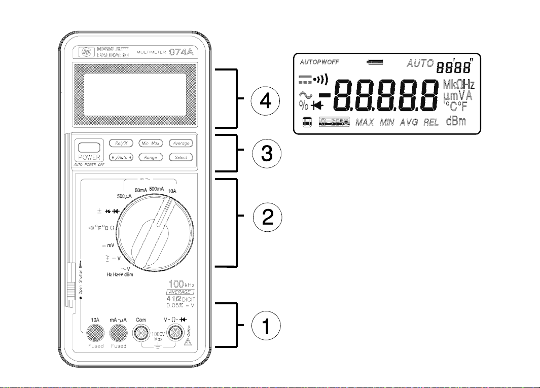
HP 974A Multimeter
User’s Guide
Part Number 00974-90002
March 1995
© Copyright Hewlett-Packard Company 1994, 1995
All Rights Reserved
Page 2
Page 3

HP 974A Multimeter
Table of Contents
Safety Summary . . . . . . . . . . . . . . . 1-4
Safety Symbols . . . . . . . . . . . . . . 1-4
Maximum Overvoltage Limitations . . . 1-5
Probes and Test Leads . . . . . . . . . 1-6
Operation . . . . . . . . . . . . . . . . . . . 1-7
Terminals, Shutter, & Test Leads . . . 1-7
Function Switch . . . . . . . . . . . . . . 1-8
Function Keys . . . . . . . . . . . . . . . 1-9
Function Keys/Function Switch Matrix . . 1 -1 2
Display . . . . . . . . . . . . . . . . . . . 1-13
Audio . . . . . . . . . . . . . . . . . . . . 1-13
Calibration and Adjustment . . . . . . . . 1-14
Required Test Equipment . . . . . . . . 1-14
Calibration Procedure . . . . . . . . . . 1-14
Specifications . . . . . . . . . . . . . . . . 1-17
General . . . . . . . . . . . . . . . . . . . 1-17
DC Voltage . . . . . . . . . . . . . . . . . 1-17
AC Voltage . . . . . . . . . . . . . . . . 1-17
AC + DC Voltage . . . . . . . . . . . . . 1-18
DC Current, AC Current . . . . . . . . . 1-18
Resistance . . . . . . . . . . . . . . . . . 1-19
Continuity . . . . . . . . . . . . . . . . . . 1-19
Diode . . . . . . . . . . . . . . . . . . . . 1-19
Frequency (AC Coupled) . . . . . . . . . 1-19
Temperature . . . . . . . . . . . . . . . . 1-20
dBm . . . . . . . . . . . . . . . . . . . . . 1-20
Adjustments . . . . . . . . . . . . . . . . . 6-1
Calibration Table . . . . . . . . . . . . . . . 6-2
Maintenance . . . . . . . . . . . . . . . . . 1-15
Battery Replacement . . . . . . . . . . . 1-15
Fuse Replacement . . . . . . . . . . . . 1-15
Troubleshooting . . . . . . . . . . . . . . 1-16
Cleaning . . . . . . . . . . . . . . . . . . 1-16
Replaceable Parts/Accessories . . . . . 1-16
Replaceable Parts/Accessories . . . . . . 6-4
Disassembly . . . . . . . . . . . . . . . . 6-5
Declaration of Conformity
1-3
Page 4
Safety Summary
The CAUTIONS and WARNINGS w hich ap pear on the fol lowing pag es mu st be follow ed to
ensure operator safety and to retain the operating condition of the Multimeter.
1. Do not use this product beyond its specifications or for uses not intended for this product
as identified b y the prod uct func tions, rang es, an d haza rds as in dicted below .
2. To minimize poss ible elec tric shock ha zard con dition, co nnect onl y two leads at an y one
time to any of the multimeter terminals.
3. To prevent poss ible elec tric shock ha zard con dition whe n using the current function, do not
leave one probe connected to the circuit under test and the other probe disconnected,
exposed, and rea dily a ccessi ble (touch able ).
Safety Symbols
Indicates the operator must refer to an explanation in this manual.
Indicates termina ls at whic h dangerou s voltage s may exist.
WARNING
TO AVOID ELECTRICAL SHOCK or damage to the m ultimet er, do not a pply mor e than
±1000 Vd c or 1000 Vr ms between an y termin al and eart h ground . Use caution when work ing with
voltages abo ve 6 0 Vdc or 4 2 Vpea k. Ens ure test le ads are in go od c ondit ion.
WARNING
POSSIBLE ELE CTRIC AL SHOC K. Do not m ake m eas ureme nts if the case i s dam age d or t he
rear cover is removed. Remove all electrical inputs before removing the rear cover.
WARNING
POSSIBLE ELECTRICAL SHOCK or FIRE HAZARD. Do not expose this multimeter to rain or
moisture. Do not oper ate the multi meter in the presence of flam mable gas es or fumes.
1-4
Page 5
Safety Summary
WARNING
POSSIBLE ELE CTRIC AL SHOC K. Ca librat ion a nd p erfo rmanc e test s are to b e pe rform ed by
qualified personnel only. Do not attempt calibration or test procedures unless qualified to do so.
CAUTION
To avoid damage to the multimeter fo r inputs abov e 250 Vdc or Vac, dis connect th e test leads
before changing functions. Do not exceed the maximum input limits.
Maximum Overvoltage Limitations (AC and DC Voltage Functions)
1000V
MA X indicates the ma ximu m voltag e be tw een i npu t ter mina ls an d ea rt h is ± 1000 V (dc or ac rms).
Do not use the multimeter on any ACV circuit where the maximum impulse overvoltage may
be more tha n 4000 Vpk or an y DCV c ircui t whe re th e ma ximu m imp ulse overvo ltage ma y be
more than 2500Vpk between the COM and VOLT terminals. Excessive impulse overvoltage
can damage the multimeter voltage functions. Do not measure branch circuits (CAT II) over
600V to earth or service pa nel circui ts (CAT III) over 30 0V to earth.
1-5
Page 6

Safety Summary
Function Maximum Operating Input
10 A
mA or µA ± 500 mA (dc or ac rms) / 250 V
Resistance , Di ode Te st,
Temperature, Continuity
Frequency
(10 Hz to 9.999 kHz)
(9 kHz to 200 k Hz)
V
± 10 A (dc or ac rms ) / 600 V
500 V (dc or ac rms)
500 Vrms
100 Vrms
± 1000 Vdc or 750 Vrms
Probes and Test Leads
1. Always inspect probes before use. Do not use test leads whose insulation has cuts,
cracks, or oth er d amage tha t may r esul t in r educ ed e lectr ic sh ock pr otectio n.
2. Keep insulation surface clean between the probe tip connector and the finger guards.
3. If probes other than the on es specified are to be used wi th the multi meter, be sure th e
probes and their leads are rated for the voltage and current to which they will be subjected.
Do not exceed the voltage ratings for the multimeter.
4. Probes supplied with this multimeter are rated for use up to 1000Vrms or Vdc.
1-6
Page 7
Operation
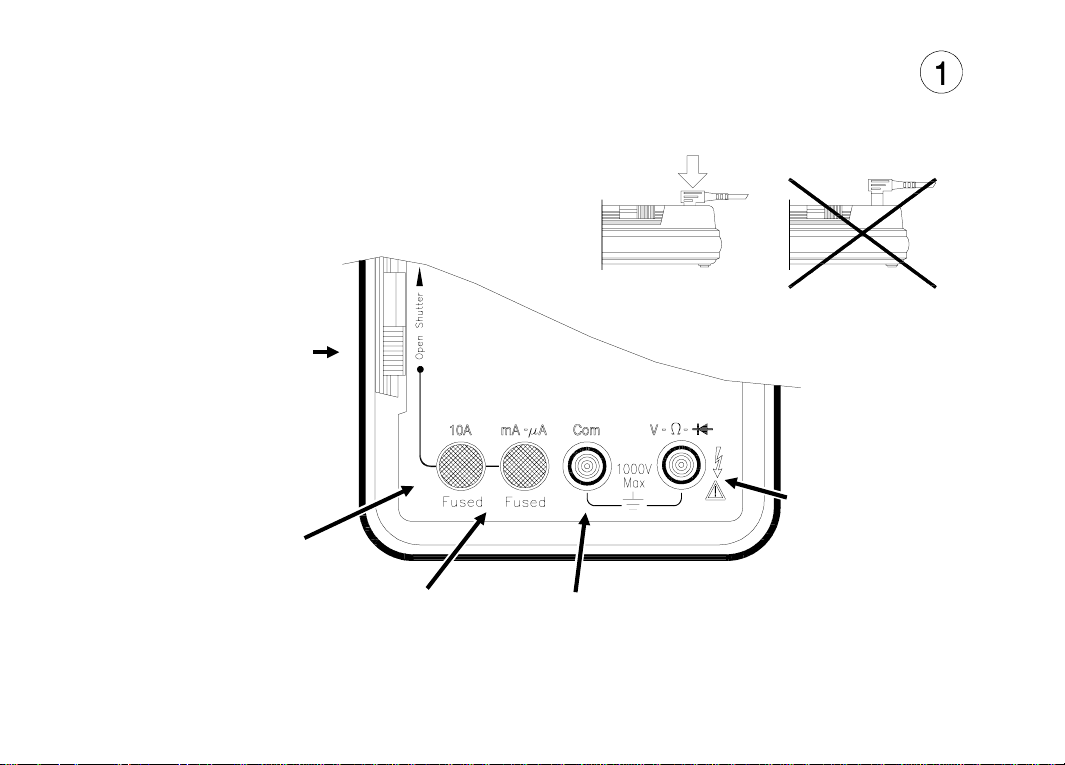
Terminals, Shutter, & Test Leads
SAFETY SHUTTE R
Slide up to open shutters
for current measurement
inputs. Must have the
function switch in one of
the Current Measurement
positions to open shutter.
Close shutter to change
function switch to any
other measurement
function.
RED LEAD
Current Measurements
(0 A to 10 A)
RED LEAD
DC & AC Voltage,
Diode, Resistance,
Frequency, Temperature, dBm
and Continuity Measurements
RED LEAD
Current Measurements
(0 to 400 mA)
BLACK LEAD
COMMON
ALL Measurements
1-7
Page 8
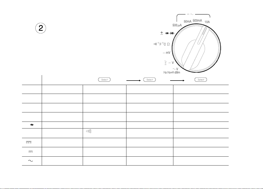
Operation
Function Switc h
Switch
Position
10A
500 mA
50 mA
500 µA
Ω
mV
1-8
Display
DC Current
(1 mA to 10 A)
DC Current
(10 µA to 0.5 A)
DC Current
(1 µA to 0.05 A)
DC Current
(0.01 µA to 0.5 mA)
Diode Test Auto Diode Test
Resistance
( 0.01 Ω to 50 MΩ)
DC Millivolts
(10 µV to 500 mV)
V
V
DC Volts
(100 µV to 1000 V)
AC Volts
(1 mV to 750 V)
1
Voltage and frequency readings alternate on display
AC Curre nt
(1 mA to 10 A)
AC Curre nt
(10 µA to 0.5 A)
AC Curre nt
(1 µA to 0.05 A)
AC Curre nt
(0.01 µA to 0.5 mA)
Continuity
(alarm at < 100 Ω)
AC + DC Volts
(1 mV to 750 V)
Frequency
(10 Hz to 200 kHz)
Temperature in °F
(-112° F to 302° F)
Frequency and Volts
(10 Hz to 200 kHz)
Temperature in °C
(-80° C to 150° C)
1
(-59.94 dBm to 62.22 dBm)
dBm
Page 9
Operation
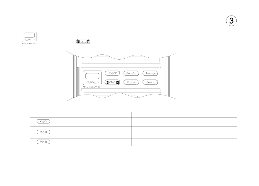
Function Key s
Power
Automatic power of f after 30 min utes. Alarm so unds 30 se conds be fore autom atic pow er off.
Press any key or change any function to cancel automatic power off. Defeat automatic power
off by holding key for 2 seconds whil e applyi ng power .
Relative/Percent
Press Action Main Display Secondary Display
Makes the displ ayed mea surem ent
Calculates the percentage change
Cancels the Relative/% function Measurement value Range
Perform a zero adjust when using the 500 Ω range and displayed val ue is less than 99 by shorting the test
leads and pressing this key. Cycle power to erase the stored zero adjustment.
the reference
from the reference
Each measured value relative to
the reference value (difference)
Each measured valu e as a
percent chan ge o f the refere nce
value
Range
Range
1-9
Page 10

Operation
Minimum/Maximum 1
Press Action Main Display Secondary Display 2
Begin recording of min, max, and avg
values
Display recorded maximum Maximum measurement Time of Maximum
Display recorded minimum Minimum measurement Time of Minimum
Display recorded average Calculated average Elapsed time
Display last reco rded m eas ureme nt Latest measu remen t Elapsed time
Pause recording of minimu m and
Resume recording of minimum and
maximum values
maximum values
Press and hold 1 second to cancel - -
1
Automatic power off is disabled when Min/Max is selected.
2
Time is recorded and displayed in minutes and seconds up to 99’ 59". After 99’ 59" tim e is recorded and
displayed in minutes up to the maximum recording time of 1999 minutes. Recording will stop at the
maximum time.
3
Average is computed from all readings during elapsed time.
3
Each measured valu e Elapsed time
Last measured valu e Total elapsed t ime
Each measured valu e Elapsed time
Average
Press Action Main Display Secondary Display
Makes the displ ayed mea surem ent the
average of the last eigh t measu remen ts
Disables the averaging of measurements Each measurement Range
Average value of last eight
measurements
Range
1-10
Page 11

Operation
Hold/Auto-Hold
Press Action Main Display Secondary Display
Holds the measureme nt value in th e
Enters Aut o-Ho ld fun ctio n
display
1
Input value Range
Measurement valu e when
hold pressed
Range
Cancels Hold f unction Measurement v alue Range
1
Auto-Hold Operation. When measurement becomes stable, multimeter will beep and save the
stable reading. Removing probe from measurement circuit will display and hold the last stable reading.
Range
Press Action M ain Display Secondary Display
Changes from auto -ran ging to ma nual
Change manual ra nge UP onc e with
Returns to auto-ranging when key is held
1
When upper range is reached, the sequence begins again at the lowest range.
ranging
each keypress
for 1 second
1
Measurement value Range
Measurement v alue Range
Measurement v alue Range
Select
Press this key to u se the fun ction s ind icate d in ye llow on the mu ltim eter. Se e table on pa ge 1- 8.
Hold this key to test display when turning meter on.
1-11
Page 12

Operation
Function Keys and Function Switch Matrix
Function Relative
µA, mA, 10A
µA, mA, 10A
••••••
••••••
%
(Percent)
Min/Max 3 Average Data Hold Auto-Hold Range
•• • • •
Ω
°F, °C
mV
V
V
Hz Hz+V
dBm
1
Invokes zero adjust when display is less than 99.
2
Changes input attenuator, frequency is always auto range.
3
Secondary display shows elapsed time (in seconds and minutes).
1
•
••••••
•• •
•• • • •
•••••••
•••••••
••
•
•
••
••
2
1-12
Page 13

Display
Low Battery indicator
Replace batteries when on.
Main Display
(Not all annunciators shown)
Number of digits is set by range and function
Displays O.L to indicate an overload condition
Entire display flashes if input overvoltage
Audio
Operation
Secondary Display
Shows:
Range (most functions)
except for
Elapsed time (Min/Max)
Power on
First beep at po wer on.
Second beep when beginning to make measurements.
Single beep
Indicates any valid function key press.
Indicates a new High or Low value recorded when in Min/Max function.
Steady repeatin g beep
Indicates when measurement is steady when using Auto-Hold function.
Rapid repeatin g be eps
Indicates wro ng in put term in als u se d fo r fu ncti on sel ecte d.
Indicates an over load cond ition at the measureme nt termi nals.
Continuous tone
Indicates a resistance of < 100 Ω when using the Continuity fun ction.
Auto Power Off
Pairs of beeps for 30 seconds.
Long beep just before power off.
Cancel by changing function switch position or pressing any key.
1-13
Page 14

Calibration and Adjus tment
Required Test Equipment
The source used for the calibration should have an output accuracy as good or better than
that listed in the specifications.
Calibration Procedure
Environmental range for calibration: 23° C ± 5° C, < 80% RH
Calibration in terval : 6 Mo nths
1 Disconnect all inputs from the multimeter and open the case as described on page 6-5.
2 Install new batteries (described below) and close the cover. Turn the multimeter on and allow a
30 minute warm-up. Open the case.
3 Set the multimeter function and range and the source output to the values specified at each step
in the calibrati on table on page 6-2.
4 When appropri ate, make th e adjustme nts indi cated in th e calibrat ion table to bring the m ultimeter
display within the limits.
CAUTION
Dangerous voltages are present during the calibration procedure. Calibration should only be
performed by qualified service technicians Use a non-conductive adjustment tool.
1-14
Page 15

Maintenance
Operator protection from electric shock hazard is provided by a double insulated enclosure.
Refer to pages 1-4 and 1-5 for maximum voltage specifications. When servicing, use only
specified repla cement pa rts.
Battery Replacement
Replace the battery when the symbol appears in the display or before calibration. Replace
both batteries at the same time. Use high-quality type AA alkaline (IEC LR6) batteries.
Remove the batteries if the multimeter is to be stored for extended periods of time. Refer to
the disassembly drawi ng on pag e 6- 5.
Fuse Replacement
Fuse locations are sh own in the dia gram on pag e 6-5. Fuses ar e listed in the replaceabl e part
list on page 6-4.
CAUTION
For continued protection use only the specified manufacturers part number or HP part number
fuse for replacem ent purpos es.
1-15
Page 16

Maintenance
Troubleshoo ting
Problem Possible Cause Suggested Act ion
Unit won’t turn on Dead Batteries
Unit won’t turn off Input limit exceeded
Display flashes and Rapid
beeps
Input limit exceed ed
Replace batteries
Remove test lead s and pres s any key to reset.
Remove test lead s and pres s any key to reset.
Battery Annun ciator on Low battery vo ltage
Unable to measure current
10 A or mA - µA
Blown input pr otec tion fu se
Cleaning
Wipe instrumen t wit h a soft r ag d ampen ed w ith soa p an d wa ter. D o no t imm erse i n wat er.
Do not use chemical cleansers or solvents.
Replaceable Parts/Accessories
Refer to the disassembly diagram on page 6-5.
1-16
Replace batteries
Replace fuse(s)
Page 17

Specifications
Calibration period: six months minimum. Specifications apply at 23°C ± 5°C, < 80% RH
Accuracy = ± (% of reading + number of digits)
Temperature Coefficient = Accuracy 0.1/° C (0° C to 18° C; 28° C to 55° C)
General
Do not expose product to moisture or rain. Do not use product in flammable atmosphere.
Operating Temperature: 0° to 40°C / 80% RH max (no condensation).
Storage Temperature: -25°C to 60°C / 20% to 70°C RH (no condensation).
Display reading rate: Approximately 2 — 4 times/second
Display rate for frequency measurements: Approximately 1 times/second
Battery life: Approximately 120 hours on DCV
DC Voltage
Range Resolution Accuracy Input Resistance
500 mV
5 V
50 V 1 mV
500 V 10 mV
1000 V 100 mV
Normal Mode Rejection Ratio: (NMR) > 60 dB @ 50 or 60 Hz
Effective Common Mode Rejection Ratio (CMR) 1 k Ω imbalance: > 120 dB @ 50 or 60 Hz
AC Voltage (RMS responding, calibrated to display rms)
Range Resolution
500 mV
5 V
500 V 10 mV
750 V 100 V
10 µV
100 µV
20 Hz to
50 Hz
± (1% + 30)
± (1% + 30) 20 Hz to 1 kHz
10 µV
100 µV
± (0.0 5% + 2)
Accuracy
50 Hz to
10 kHz
± (0.7% +30) ± (2% + 50)
± (0.5% + 30) ± (1% + 40) ± (2% + 70) ± (3% + 300)50 V 1 mV
10 kHz to
30 kHz
> 1000 MΩ
11 MΩ (nominal)
10 MΩ (nominal)
30 kHz to
50 kHZ
Not Specified
Not Specified
50 kHz to
100 kHz
Input
Impedance
(nominal)
11 M Ω
< 50 pF
10 M Ω
< 50 pF
1-17
Page 18

Specifications
AC + DC Voltage (rms responding, computed from acV, dcV)
Range Resolution
5 V 1 mV
50 V 10 mV
500 V 100 mV
750 V 1 V
Measurement range:
500 mV to 500 V ranges 20 Hz to 30 kHz 5% to 100% of range
750 V range 75 V to 750 V
Response time: < 2 seconds for AC, 5 seconds for AC+DC on fixed range
Crest factor: <3
Common Mode Rejection Ratio (CMR) 1 k Ω imbalance: > 60 dB @ DC to 60 Hz
DC, 20 Hz to
10 kHz
± (1% + 30) ± (1.2% + 40) ± (2.5% + 70) ± (3.5% + 300)
± (1% + 30)
DC, 20 H z to 1 k Hz
30 kHz to 100 kHz 10% to 100% of range
DC, 10 kHz to
30 kHz
Accuracy
DC, 30 kHz to
50 kHZ
Not Specified
DC Current, AC Current (40 Hz to 1 kHz), 5% to 100% of range
Range Resolution
500 µA
500 mA
10 A 1 mA
10 nA
1 µA< 12 Ω
10 µA < 2.5 Ω
DC Current
Accuracy
± (0.3% + 2)
± (0.7% + 2) < 0.05 Ω
AC Current
Accuracy
± (1% + 20)
Input
Resistance
< 1050 Ω
DC, 50 kHz to
100 kHz
Maximum
Input
0.5 A (fused)50 mA
15 A (fused)
1-18
Page 19

Resistance
Range Resolution Accuracy Test Curr ent
500 Ω 10 mΩ± (0.06% + 2)
5.0 kΩ 100 mΩ
1
< 800 µA
± (0.06% + 2) 50 kΩ 1Ω < 80 µA
500 kΩ 10 Ω < 15 µA
5.0 MΩ 100 Ω ± (0.5% + 1) < 1.5 µA
50 MΩ 1 kΩ ± (1.0% + 2)
1
After zero adjust of input leads. Zero adjust range up to 0.99 Ω.
Response time: 500 Ω to 500 kΩ — < 2 seconds, 5 MΩ to 50 MΩ — < 10 seconds.
< 150 nA
Max
Open Circuit
Voltage
< 5.5 V
< 2.2 V
Continuity
Measurement Current: 0.8 mA maximum Open circuit voltage: < 5.5 Vpeak
Displayed resistance: 0 Ω to 499.99 Ω Input protection: 500 Vrms (sinewave)
Alarm: Tone when input < 100 Ω ± 50 Ω Resolution: 10 mΩ (<100 m Sec response time)
Diode
Measurement current: +1.0 mA nominal @ 0.6 V Open circuit voltage: < 5.5 Vpeak
Displayed Voltage: 0 V to 4.999 V Input protection: 500 Vrms (sinewave)
Accuracy: ± (1% + 2) Resolution: 100 µV
Frequency (AC Coupled)
Frequency Range Resolution Accur acy Input Voltage (rms)
10 Hz to 99.99 Hz 0.01 Hz
0.45 mV to 500 V90 Hz to 999.0 Hz 0.1 Hz
900 Hz to 9.999 Hz 1 Hz
9.00 kHz to 99.99 kHz 10 Hz .7 V to 100 V
90 kHz to 200 kHz 100 Hz 1.5 V to 100 V
± (0.05% + 1)
Specificatio ns
1-19
Page 20

Specifications
Temperature (5 kΩ @ 25°C Thermis tor pr obe)
°C °F
Measurement Range
Resolution
1
1
Accuracy
Accuracy does not include 5 k Ω Thermistor error
-80° to 150° -112° to 302°
0.1° 0.1°
± 0.2°± 0.4°
dBm 600 Ω 1 mW reference (rms responding, computed from AC Voltage)
Input dBm I nput Voltage
-29.82 dBm to
-23.80 dBm
-23.80 dBm to
-3.80 dBm
-3.80 dBm to
55.28 dBm
55.28 dBm to
59.72 dBm
Dynamic range: -59.94 dBm to 59.72 dBm (0.8 mV to 750 V),
Accuracy not specified below -29.82 dBm (25 mV)
Display reads OL (overload) outside dynamic range
25 mV to 50 mV
50 mV to 499.99 mV
0.5 V to 450.00 V
450 V to 750 V
20 Hz to
10 kHz
± 0.2 dBm ± 0.50 dBm
± 0.15 dBm ± 0.30 dBm
± 0.10 dBm ± 0.20 dBm
± 0.15 dBm
to 1kHz
Accuracy
10 kHz to
30 kHz
30 kHz to
50 kHz
50 kHz to
100 kHz
Not specified
± 0.5 dBm ± 1.00 dBm
Not specified
1-20
Page 21

Adjustments
6-1
Page 22

Calibration Table
CAUTION
Dangerous voltages are present during the calibration procedure. Calibration should only be
performed by qua lifie d se rvice t echn ician s usin g a non- cond uctive tool.
Step Function Range Input Signal
1
2 480.0 mV
3 -480.0 mV —
4
5 -48.000 V —
6 5 V 4.800 V
7 500 V 480.00 V
8 1000 V 1000 V
*
9
*
10
11 500 mV 480.0 mV @ 200 Hz
12
13 480.00 V @ 100 kHz —
14 480.00 V @ 200 Hz —
15
16 4 .8000 V @ 100 kHz —
*Repeat steps 9 and 10.
6-2
500 mV
V
V
500 mV
50 V
5 V
500 V
5 V
Short —
48.000 V
4.8000 V @ 200 Hz
0.2500 V @ 200 Hz
480.00 V @ 10 kHz
4 .8000 V @ 10 kHz
Adjustment
(limit)
1 (±2) ±26
2 (±2) ±26
3 (±2) ±26
RV4 (±2) ±26
RV5 (±1) ±7
6 (±10) ±270
7 (±5) ±42
8 (±10) ±366
C1 (±20) ±27 0
C2 (±20) ±27 0
Tolerance
(counts)
±2
±26
±26
±1740
±270
±1740
Page 23

Calibration Table
Step Function R ange Input Signal
17
18 48.000 V @ 100 kHz —
19 48.000 V @ 200 Hz —
V
50 V
48.000 V @ 10 kHz
Adjustment
C3 (±20) ±27 0
20 500 mV 480.00 mV @ 10 kHz —
21 750 V 750.0 V @ 200 Hz —
22
23
24
25
26
27
28
29
30
31
32
33
34
35
36
37
38
500 Ω
5 kΩ 4.8000 kΩ
Ω
50 kΩ 48.000 kΩ
500 kΩ 480.00 kΩ
5 MΩ 4.80 00 MΩ
50 MΩ 48 .000 MΩ
500 µA500 µA
50 mA
500 mA
10 A
50 mA 48.000 mA —
40 mA 480.00 mA —
10 A 10.000 A
500 µA500 µA 480.00 µA @ 200 Hz
50 mA
500 mA
10 A
50 mA 48.000 mA @ 200 Hz —
500 mA 48 0.00 mA @ 20 0 Hz —
10 A 10.00 A @ 200 Hz —
500 Ω 0 Ω to 150 Ω
Short zero adjust
480.00 Ω 9 (±5) ±30
Short —
480.00 µA
10 (±10) ±72
39 5 V 1.000 V —
40 Hz 5 V 9.000 kHz @ 1 Vr ms —
1
Perform zero adjustment using key.
(limit)
—
—
—
—
—
—
—
—
Tolerance
(counts)
±1740
1
Tone < 100 Ω
±270
±366
±105
±1
±30
±30
±30
±242
±482
±2
±146
±146
±146
±500
±500
±500
±120
±102
±5
6-3
Page 24

Replaceable Parts/ Accessorie s
Refer to the disassembly diagram on page 6-5.
Call out Description HP Part Number
Fuse, 500 mA, 250 V fast blow Littlefuse 216-500
F1
F2
MP1 Top case assemb ly 0097 4-6440 1
MP2 Dust/moisture se al 0097 1-6440 3
MP3 Bottom case assem bly ( includ es sta nd) 00974- 6440 2
Operator protection from electric shock hazard is provided by a double insulated enclosure. Refer to the Safety
Summary for maximum voltage specifications. When servicing, use only specified replacement parts.
Fuse, 15 A, 600 V fa st blo w L itt lefu se KLK1 5
DO NOT SUBSTITUTE
DO NOT SUBSTITUTE
Rubber Boot 00971-86001
Replacement Test Leads, 2 pair E2305A
Temperature probe, 5 KΩ Thermistor
Surface temperature sensor,
12" lead, require s dual bana na plug
Thermistor ±0.1°C
(fits meter with ru bber boo t)
Soft Case
2110-0940
2110-0941
E2308A
40653B
E2304A
6-4
Page 25

Disassembly
WARNING
Always disconnect the test leads before opening the case.
Replaceable Parts/Accessories
6-5
Page 26

DECLARATION OF CONFORMITY
according to ISO / IEC Guide 22 and EN 45014
Manufacturer ’s Name: Hewlett- Packard Company, Personal Measurements Operation
Manufacture r’s Add ress: 815 14th S treet S.W., Loveland, Colorado 80537 U.S.A.
declares, that the products
Product Name:
Model Number: HP 971A, HP 972A, HP 973A, HP 974A
Product Options: None
conforms to the following Product Specifications:
Safety:
EMC: CISPR 11:1990 / EN55011 (1991): Group 1, Class A
IEC 1010-01 (1990) Incl. Amend 1 (1992) / EN61010 (1993)
CSA C22.2 #1010.1 (1992)
UL 1244
Handheld Multimeter
IEC801-2:1991 / EN50082-1 (1992): 4 kV CD, 8 kV AD
IEC 801-3:1984 / EN50082-1 (1992): 3 V/m
IEC 801-4:1988 / EN50082-1 (1992): 0.5 kV Signal Lines
Supplemental Information: The product herewith complies with the requir ements of the
Low Voltage Directive 73 / 23 / EEC and the EMC Directive 89 / 336 / EEC amended
by 93 / 68 / EEC (inclusive 93 / 68 / EEC) and carries the CE mark accordingly.
Loveland, Colorado April 1, 1994
Jim White, QA Manager
European Con tact: Y our l ocal Hewle tt-Pac kard S ales and Service Offic e or H ewlet t-Pack ard GmbH,
Department ZQ / Standards Europe, Herrenberger Straβe 130, D-71034 Böblingen (FAX: +49-7031-143143).
Page 27

Warranty/Service
Limited 3 Year Warranty
What is Covered
The HP 974A Multimeter is warranted by Hewlett-Packard against defects in materials and
workmanship for three years from the date of original purchase. If you sell your uni t or give it as
a gift, the warranty is automatically transferred to the new owner and remains in effect for the
original three year period. During the warranty period, we will repair, or at our option, replace at
no charge, a product that proves to be def ective, provided you return the product, shippi ng
prepaid, to a Hewlett-Packard service center.
What is Not Covered
This warranty does not apply if the product has been damaged by accident of misuse or as the
result of service or modification by other than an authori zed Hewlett-Packard service center.
No other express warranty is given. The repair or replacement of a product is your exclusive
remedy. ANY OTHER IMPLIED WARRANTY OF MERCHANTABILITY OR FITNESS IS LIMITED
TO THE THREE YEAR DURATION OF THIS WRITTEN WARRANTY. Some states, provinces, or
countries do not allow the exclusion or lim itati on or inci dental or co nsequential damages, so the
above limitation or exclusion may not apply to you.
The warranty gives you specific legal rights, and you may also have other rights which vary
from state to state, province to province, or country to country.
Service
Hewlett-Packard maintains service centers in many countries throughout the world. You may
have your unit repaired at a Hewlett-Packard service center any time it needs service, whether
the unit is under warranty or not. There is a charge for repairs after the warranty period. Repair
or replacement during the first 30 days after purchase will be provided by the sales channel.
After 30 days, contact the nearest service office.
Hewlett-Packard products normally are repaired and reshipped within five (5) working days of
receipt at any service center. This is an average time and could possibly vary depending upon
the time of year and work load at the service center. The total time you are without your unit will
depend largely on the shipping ti me.
 Loading...