

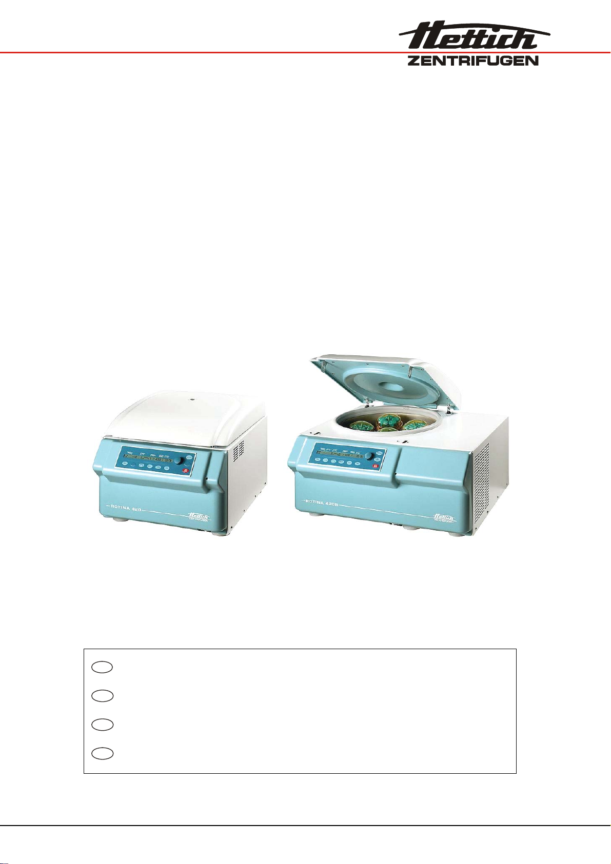
ROTINA 420
ROTINA 420 R
DE
Bedienungsanleitung...................................................... 10
EN
Operating Instructions.................................................... 45
FR
Mode d'emploi................................................................. 79
IT
Istruzioni per l'uso ..........................................................116
Rev. 05 / 11.13 Andreas Hettich GmbH & Co. KG AB4701DEENFRIT
A
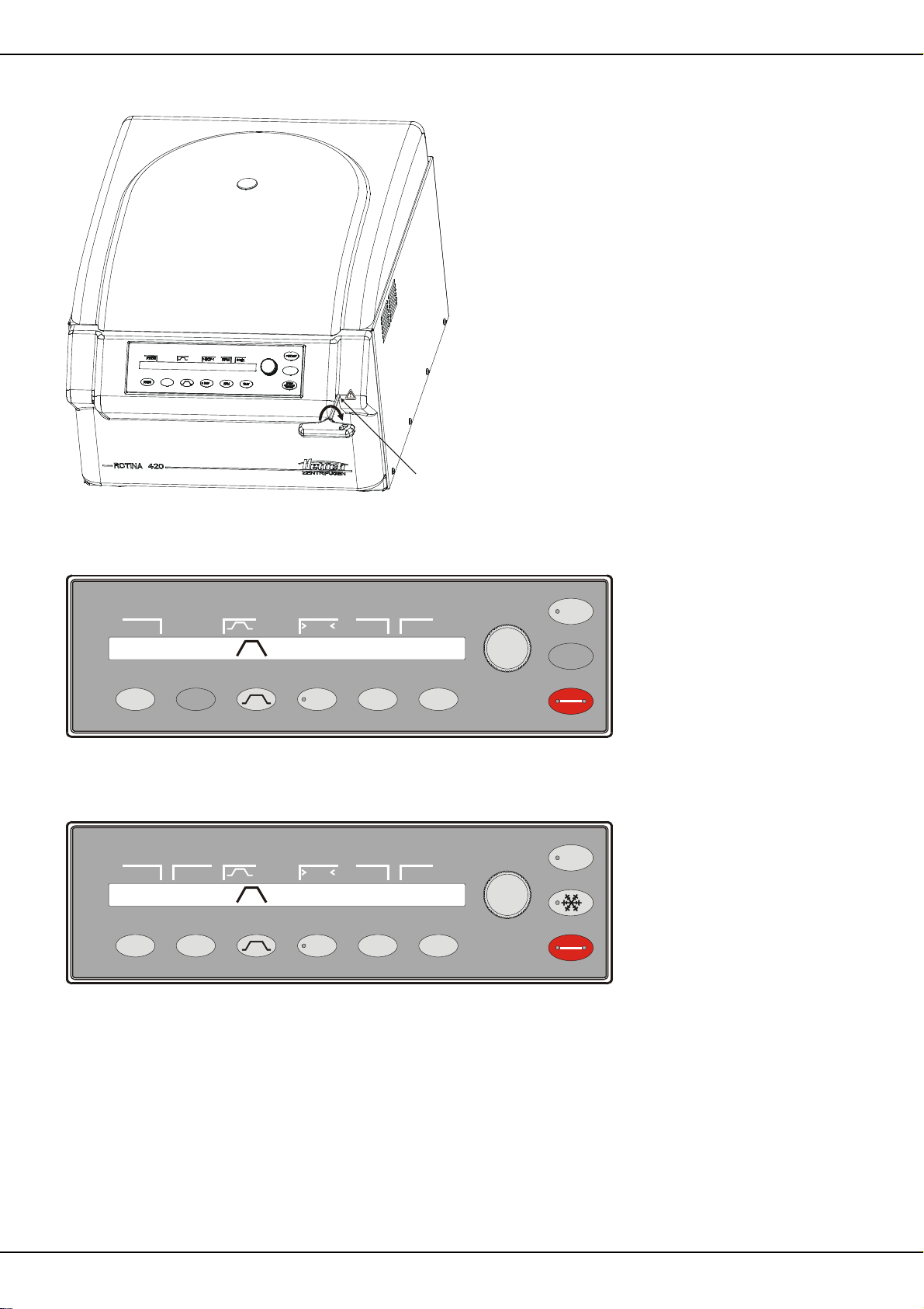
Fig. 1
PROG
1
PROG RCF RPM TIME
Fig. 2 ROTINA 420
PROG T/°C RCF
PROG T/°C RCF RPM TIME
Fig. 3 ROTINA 420 R
99
RCF
RPM
RPM
t/min
12:304500
t/min
12:30450020199
START
STOP
OPEN
START
STOP
OPEN
2/178

EG-Konformitätserklärung
EC Declaration of conformity
Déclaration de conformité CE
Dichiarazione di conformità CE
des Herstellers / of the manufacturer / du fabricant / del costruttore
Andreas Hettich GmbH & Co. KG Föhrenstraße 12 D-78532 Tuttlingen Germany
Hiermit erklären wir in alleiniger Verantwortung, dass das bezeichnete Gerät, inklusive dem mit dem Gerät
konformitätsbewertetem Zubehör laut Zubehörliste der technischen Dokumentation dieses Geräts, der Richtlinie über
In-vitro-Diagnostika 98/79/EG entspricht.
We hereby declare under our sole responsibility that the designated device and its accessories, which are listed in
the technical documentation for this device and whose conformity has been assessed together with the device,
conform to the Directive 98/79/EC on in vitro diagnostic medical devices.
Par la présente, nous déclarons sous notre seule responsabilité que l'appareil désigné, incluant ses accessoires
attestés conformes d'après la liste des accessoires de la documentation technique du dit-appareil, répond à la
directive 98/79/CE sur le diagnostic In-vitro.
Si dichiara nella nostra sola responsabilità, che l'apparecchiatura indicata, comprensiva dei conformi accessori come
da elenco della documentazione tecnica di questa apparecchiatura, risponde alle direttive per Diagnostica In-Vitro
98/79/CE.
Geräteart / Type of device / Type d'appareil / Tipo di apparecchio:
Laborzentrifuge / Laboratory centrifuge / Centrifugeuse de laboratoire / Centrifuga di laboratorio
Typenbezeichnung / Type designation / Désignation du type / Denominazione del tipo:
ROTINA 420 / ROTINA 420 R
Das Konformitätsbewertungsverfahren wurde nach Anhang III der Richtlinie 98/79/EG durchgeführt.
The conformity evaluation process was performed in accordance with appendix III of Directive 98/79/EC.
La procédure d'évaluation de la conformité a été réalisée conformément à l'annexe III de la directive 98/79/CE.
La procedura di valutazione di conformità è stata eseguita conformemente all'appendice III delle direttive 98/79/CE.
Angewandte Normen und Richtlinien:
Gemäß Liste der angewandten Normen und mitgeltenden Richtlinien, die Teil der Produktakte ist.
Applied standards and directives:
According to the list of applied standards and valid directives which is part of the product documentation.
Normes et directives appliquées:
Conformément à la liste des normes et directives applicables et appliquées qui font partie du dossier relatif au
produit.
Norme e direttive applicate:
Conformemente alla lista delle norme applicate e delle direttive di validità, che sono parte degli atti del prodotto.
3/178

Tuttlingen, 2012-05-15
H. Eberle
Geschäftsführer, Manager,
Directeur, Gerente
4/178

Für dieses Gerät gültige Normen und Vorschriften
Das Gerät ist ein Produkt mit einem sehr hohen technischen Niveau. Es unterliegt umfangreichen Prüf- und
Zertifizierungsverfahren gemäß folgenden Normen und Vorschriften in deren jeweils gültigen Fassung:
Elektrische und mechanische Sicherheit für Konstruktion und Endprüfung:
Normbaureihe: IEC 61010 (entspricht der Normenreihe DIN EN 61010)
IEC 61010-1 “Sicherheitsbestimmungen für elektrische Mess-, Steuer-, Regel- und Laborgeräte - Teil 1:
Allgemeine Anforderungen” (Verschmutzungsgrad 2, Installationskategorie II)
IEC 61010-2-010 “Sicherheitsbestimmungen für elektrische Mess-, Steuer-, Regel- und Laborgeräte – Teil
2-010: Besondere Anforderungen an Laborgeräte für das Erhitzen von Stoffen (nur für Zentrifugen mit
Heizung gültig)
IEC 61010-2-020 “Sicherheitsbestimmungen für elektrische Mess-, Steuer-, Regel- und Laborgeräte - Teil 2-
020: Besondere Anforderungen an Laborzentrifugen
IEC 61010-2-101 ”Sicherheitsbestimmungen für elektrische Mess-, Steuer-, Regel- und Laborgeräte - Teil 2-
101: Besondere Anforderungen an In-vitro-Diagnostik (IVD) Medizingeräte
Elektromagnetische Verträglichkeit:
EN 61326-1 “Elektrische Mess-, Steuer-, Regel- und Laborgeräte - EMV-Anforderungen - Teil 1: Allgemeine
Anforderungen
Für Konformitätsbewertungsverfahren geltende Europäische Richtlinien:
Richtlinie 98/79/EC über In-vitro-Diagnosegeräte
EG-Konformitätsbewertungsverfahren gemäß Anhang III "EG-Konformitätserklärung" – Eigenerklärung des
Herstellers
Weitere, mitgeltende europäische Richtlinien:
Maschinenrichtlinie 2006/42/EG
EMV-Richtlinie 2004/108/EG
Niederspannungsrichtlinie 2006/95/EC
Außerhalb Europas geltende Richtlinien für Medizinprodukte:
USA: QSR, 21CFR 820 “CFR Title 21 - Food and Drugs: TITLE 21- FOOD AND DRUGS, CHAPTER I -
FOOD AND DRUG ADMINISTRATION DEPARTMENT OF HEALTH AND HUMAN SERVICES,
SUBCHAPTER H - MEDICAL DEVICES, Part 820 QUALITY SYSTEM REGULATONS“
Kanada: CMDR, SOR/98-282 “Medical Devices Regulations”
Zertifiziertes Qualitätsmanagementsystem gemäß
ISO 9001 “Qualitätsmanagementsysteme - Anforderungen”
ISO13485 “Qualitätsmanagementsysteme für Medizinprodukte - Anforderungen für regulatorische Zwecke”
Umweltmanagementsystem gemäß
ISO 14001 “Umweltmanagementsysteme - Spezifikation mit Anleitung zur Anwendung”
5/178

Standards and regulations which apply to this device
The device is a high-end technical product. It is subject to extensive testing and certification procedures according to
the following standards and regulations in their respectively valid version:
Electrical and mechanical safety for design and final testing:
Standard series: IEC 61010 (conform to standards of DIN EN 61010)
IEC 61010-1 “Safety requirements for electrical equipment for measurement, control, and laboratory use -
Part 1: General requirements” (Pollution Degree 2, Installation Category II)
IEC 61010-2-010 “Safety requirements for electrical equipment for measurement, control and laboratory use
- Part 2-010: Particular requirements for laboratory equipment for the heating of materials” (applied to
heated centrifuges only)
IEC 61010-2-020 “Safety requirements for electrical equipment for measurement, control, and laboratory
use - Part 2-020: Particular requirements for laboratory centrifuges”
IEC 61010-2-101 ”Safety requirements for electrical equipment for measurement, control and laboratory use
- Part 2-101: Particular requirements for in vitro diagnostic (IVD) medical equipment“
Electromagnetic Compatibility:
EN 61326-1 “Electrical equipment for measurement, control and laboratory use - EMC requirements - Part 1:
General requirements“
European directives applied for conformity assessmen t procedures:
In vitro diagnostic device directive 98/79/EG
EC conformity assessment procedure according to annex III “EC DECLARATION OF CONFORMITY“ –
self-declaration by the manufacturer
Further partly applicable European directives:
Machinery Directive 2006/42/EC
EMC directive 2004/108/EC
Low voltage directive 2006/95/EC
Applied medical device regulations outside Europe:
USA: QSR, 21CFR 820 “CFR Title 21 - Food and Drugs: TITLE 21- FOOD AND DRUGS, CHAPTER I -
FOOD AND DRUG ADMINISTRATION DEPARTMENT OF HEALTH AND HUMAN SERVICES,
SUBCHAPTER H - MEDICAL DEVICES, Part 820 QUALITY SYSTEM REGULATONS“
Canada: CMDR, SOR/98-282 “Medical Devices Regulations”
Certified quality management system according to
ISO 9001 “Quality management systems – Requirements”
ISO13485 “Medical devices - Quality management systems - Requirements for regulatory purposes”
Environmental management system according to
ISO 14001 “Environmental management systems - Requirements with guidance for use”
6/178

Normes et règles en vigueur pour cet appareil
Cet appareil est un produit avec un très haut niveau technique. Il est soumis à des vastes procédures de vérification
et de certification, d'après les normes et prescriptions suivantes, dans leur version actuelle :
Sécurité électrique et mécanique pour la construction et l'inspection finale :
Série de normes : IEC 61010 (correspond à la série de norme DIN EN 61010)
IEC 61010-1 “Règles de sécurité pour appareils électriques de mesurage, de régulation et de laboratoire -
partie 1 : Prescriptions générales” (niveau de saleté 2, catégorie d'installation II)
IEC 61010-2-010 “Règles de sécurité pour appareils électriques de mesurage, de régulation et de
laboratoire – partie 2-010 : Prescriptions particulières pour appareils de laboratoire utilisés pour
l’échauffement des matières (seulement valable pour centrifugeuses avec chauffage)
IEC 61010-2-020 “Règles de sécurité pour appareils électriques de mesurage, de régulation et de
laboratoire – partie 2-020 : Prescriptions particulières pour centrifugeuses de laboratoire
IEC 61010-2-101 ”Règles de sécurité pour appareils électriques de mesurage, de régulation et de
laboratoire – partie 2-101 : Prescriptions particulières pour les appareils médicaux de diagnostic in vitro
(DIV)
Compatibilité électromagnétique :
EN 61326-1 “Matériel électrique de mesure, de commande et de laboratoire – Exigences relatives à la CEM
- partie 1 : Exigences générales
Directives européennes valables pour des procédures d'évaluation de la conformité :
directive 98/79/EC relative aux dispositifs médicaux de diagnostic in vitro
procédure d'évaluation de la conformité CE d'après l'annexe III "Déclaration CE de conformité" –
déclaration spécifique du fabricant
Autres directives européennes partiellement valables :
directive 2006/42/EG relative aux machines
directive CEM 2004/108/EG
directive basse tension 2006/95/EC
Directives pour dispositifs médicaux, valables en dehors de l'Europe :
USA : QSR, 21CFR 820 “CFR Title 21 - Food and Drugs : TITLE 21- FOOD AND DRUGS, CHAPTER I -
FOOD AND DRUG ADMINISTRATION DEPARTMENT OF HEALTH AND HUMAN SERVICES,
SUBCHAPTER H - MEDICAL DEVICES, Part 820 QUALITY SYSTEM REGULATONS“
Canada: CMDR, SOR/98-282 “Medical Devices Regulations”
Système de management de la qualité certifié d'après
ISO 9001 “Systèmes de management de la qualité - Prescriptions”
ISO13485 “Dispositifs médicaux - Systèmes de management de la qualité - Exigences à des fins
réglementaires”
Système de management environnemental d'après
ISO 14001 “Systèmes de management environnemental - Spécification avec description pour application”
7/178

Norme e direttive valide per questo apparecchio
L'apparecchio è un dispositivo di elevatissimo livello tecnico. È sottoposto a numerosi procedimenti di collaudo e
certificazione, in conformità alle seguenti norme e direttive nella corrispondente versione di validità:
Sicurezza elettrica e meccanica per la costruzione ed il collaudo finale:
Serie di norma: IEC 61010 (corrisponde alla serie di norma DIN EN 61010)
IEC 61010-1 “Norme di sicurezza per apparecchiature elettriche di misurazione, di comando, di regolazione
e di laboratorio - parte 1: Requisiti generali” (grado di imbrattamento 2, categoria di installazione II)
IEC 61010-2 -010 “Norme di sicurezza per apparecchiature elettriche di misurazione, di comando, di
regolazione e di laboratorio - parte 2-010: Requisiti particolari per le apparecchiature di laboratorio per il
riscaldamento di materiali (valido solo per centrifughe con riscaldamento)
IEC 61010-2 -020 “Norme di sicurezza per apparecchiature elettriche di misurazione, di comando, di
regolazione e di laboratorio - parte 2-020: Requisiti particolari per centrifughe di laboratorio
IEC 61010-2 -101 “Norme di sicurezza per apparecchiature elettriche di misurazione, di comando, di
regolazione e di laboratorio - parte 2-101: Requisiti particolari per la diagnostica In-vitro (IVD)
apparecchiature medicali
Compatibilità elettromagnetica:
EN 61326-1 “Apparecchiature elettriche di misurazione, di comando, di regolazione e di laboratorio -
requisiti di compatibilità elettromagnetica - parte 1: Requisiti generali
Direttive europee che sono di validità per il procedimento di valutazione della conformità:
Direttive 98/79/CE per apparecchiature di diagnosi In-vitro
Procedimento di valutazione di conformità CE conforme all'appendice III "Dichiarazione di conformità CE" –
Dichiarazione propria del costruttore
Ulteriori direttive europee, che sono in parte di validità:
Direttive per macchine 2006/42/CE
Direttive per compatibilità elettromagnetica 2004/108/CE
Direttive per basse tensioni 2006/95/CE
Direttive valide al di fuori dell'ambito europeo per i prodotti medicali:
USA: QSR, 21CFR 820 “CFR Title 21 - Food and Drugs: TITLE 21- FOOD AND DRUGS, CHAPTER I -
FOOD AND DRUG ADMINISTRATION DEPARTMENT OF HEALTH AND HUMAN SERVICES,
SUBCHAPTER H - MEDICAL DEVICES, Part 820 QUALITY SYSTEM REGULATONS“
Kanada: CMDR, SOR/98-282 “Medical Devices Regulations”
Certificato sistema di gestione della qualità, conforme a
ISO 9001 “Requisiti per sistemi di gestione qualità”
ISO13485 “Sistemi di gestione qualità per prodotti medicali - Requisiti per impieghi di regolazione”
Sistema di gestione ambientale, conforme a
ISO 14001 “Sistemi di gestione ambientale - Specificazione con istruzioni per l'applicazione”
8/178
Andreas Hettich GmbH & Co. KG
Föhrenstraße 12, D-78532 Tuttlingen / Germany
Phone +49 (0)7461 / 705-0
Fax +49 (0)7461 / 705-1125
info@hettichlab.com, service@hettichlab.com
www.hettichlab.com
© 2006 by Andreas Hettich GmbH & Co. KG
All rights reserved. No part of this publication may be reproduced without the prior written permission of the copyright
owner.
Änderungen vorbehalten! , Modifications reserved! , Sous réserve de modifications ! , Con riserva di modifiche!
AB4701DEENFRIT / Rev. 05 / 11.13
9/178

DE
Inhaltsverzeichnis
1 Bestimmungsgemäße Verwendung.............................................................................................................................................12
2 Restrisiken ...................................................................................................................................................................................12
3 Technische Daten ........................................................................................................................................................................ 12
4 Sicherheitshinweise .....................................................................................................................................................................13
5 Bedeutung der Symbole............................................................................................................................................................... 15
6 Lieferumfang ................................................................................................................................................................................ 16
7 Auspacken der Zentrifuge............................................................................................................................................................16
8 Inbetriebnahme ............................................................................................................................................................................ 16
9 Schnittstelle (nur bei Zentrifuge mit Schnittstelle)........................................................................................................................17
10 Deckel öffnen und schließen....................................................................................................................................................17
10.1 Deckel öffnen ...................................................................................................................................................................17
10.2 Deckel schließen.............................................................................................................................................................. 17
11 Ein- und Ausbau des Rotors ....................................................................................................................................................17
12 Beladen des Rotors.................................................................................................................................................................. 18
13 Verschließen von Bio-Sicherheitssystemen............................................................................................................................. 19
14 Bedien- und Anzeigeelemente ................................................................................................................................................. 20
14.1 Drehknopf ........................................................................................................................................................................ 20
14.2 Tasten und Einstellmöglichkeiten ....................................................................................................................................20
15 Zentrifugations–Parameter eingeben.......................................................................................................................................21
15.1 Laufzeit .......................................................................................................................
15.2 Beginn der Zählung der Laufzeit...................................................................................................................................... 22
15.3 Drehzahl (RPM) ...............................................................................................................................................................22
15.4 Relative Zentrifugalbeschleunigung (RCF) und Zentrifugierradius (RAD) ....................................................................... 22
15.5 An- und Auslauf-Parameter .............................................................................................................................................22
15.5.1 Anlaufstufe und Anlaufzeit ....................................................................................................................................... 23
15.5.2 Bremsstufe und Auslaufzeit ..................................................................................................................................... 23
15.5.3 Bremsabschaltungs-Drehzahl.................................................................................................................................. 23
15.6 Temperatur (nur bei Zentrifuge mit Kühlung)...................................................................................................................23
16 Programmierung....................................................................................................................................................................... 24
16.1 Programme eingeben oder ändern .................................................................................................................................. 24
16.2 Programme abrufen ......................................................................................................................................................... 24
16.3 Schreibschutz für Programme .........................................................................................................................................24
16.4 Programmverknüpfung .................................................................................................................................................... 24
16.4.1 Programmverknüpfung aktivieren oder deaktivieren ...............................................................................................25
16.4.2 Programme verknüpfen oder eine Programmverknüpfung ändern ......................................................................... 25
16.4.3 Programmverknüpfung abrufen ............................................................................................................................... 25
16.5 Automatischer Zwischenspeicher .................................................................................................................................... 26
17 Zentrifugation ...........................................................................................................................................................................26
17.1 Zentrifugation mit Zeitvorwahl.................................................................................................
17.2 Dauerlauf ......................................................................................................................................................................... 27
17.3 Kurzzeitzentrifugation ......................................................................................................................................................27
18 Einstellungen während des Zentrifugationslaufes ändern ....................................................................................................... 27
19 Integral RCF.............................................................................................................................................................................27
19.1 Integral RCF abfragen ..................................................................................................................................................... 27
19.2 Anzeige des Integral RCF aktivieren oder deaktivieren................................................................................................... 28
20 Not-Stop ................................................................................................................................................................................... 28
..................................................... 22
......................................... 26
10/178

DE
21 Zyklenzähler............................................................................................................................................................................. 28
21.1 Nach Start des ersten Zentrifugationslaufes die maximal zulässige Anzahl der Laufzyklen eingeben
oder den Zyklenzähler deaktivieren................................................................................................................................. 29
21.2 Zyklenzähler auf "0" zurücksetzen und die maximal zulässige Anzahl der Laufzyklen eingeben ................................... 29
21.3 Zyklenzähler deaktivieren oder aktivieren ....................................................................................................................... 30
22 Funktion "Dual time mode" aktivieren oder deaktivieren ......................................................................................................... 30
23 An- und Auslaufzeiten aktivieren oder deaktivieren................................................................................................................. 31
24 Akustisches Signal................................................................................................................................................................... 31
25 Angezeigte Zentrifugations-Daten nach dem Einschalten ....................................................................................................... 32
26 Temperatur-Einheit einstellen (nur bei Zentrifuge mit Kühlung) .............................................................................................. 32
27 Programm-Verriegelung einstellen........................................................................................................................................... 33
28 PIN (Persönliche Identifikationsnummer)................................................................................................................................. 33
28.1 PIN einstellen oder ändern .............................................................................................................................................. 34
28.2 Vorgehensweise bei verlorener PIN ................................................................................................................................34
29 Adresse der Zentrifuge............................................................................................................................................................. 35
30 Die Betriebsstunden, die Zentrifugationsläufe und die Zyklenzähler abfragen........................................................................ 35
31 System-Informationen abfragen............................................................................................................................................... 35
32 Sofortige Anzeige der Zentrifugations-Daten nach dem Einschalten ...................................................................................... 35
33 Kühlung (nur bei Zentrifuge mit Kühlung) ................................................................................................................................ 36
33.1
33.2 Vorkühlen des Rotors ...................................................................................................................................................... 36
33.3 Zeitverzögerte Kühlung.................................................................................................................................................... 36
33.4 Einschalten der Kühlung während des Auslaufs verhindern ........................................................................................... 36
34 Heizung (nur bei Zentrifuge mit Option Heizen/Kühlen) .......................................................................................................... 37
35 Relative Zentrifugalbeschleunigung (RCF) .............................................................................................................................. 37
36 Zentrifugation von Stoffen oder Stoffgemischen mit einer höheren Dichte als 1,2 kg/dm
37 Rotorerkennung ....................................................................................................................................................................... 38
38 Notentriegelung........................................................................................................................................................................ 38
39 Pflege und Wartung ................................................................................................................................................................. 38
39.1 Zentrifuge (Gehäuse, Deckel und Schleuderraum) ......................................................................................................... 39
39.2 Rotoren und Zubehör....................................................................................................................................................... 40
39.3 Autoklavieren ................................................................................................................................................................... 41
39.4 Zentrifugiergefäße ........................................................................................................................................................... 41
40 Störungen................................................................................................................................................................................. 42
41 Sicherungsautomat einschalten............................................................................................................................................... 44
42 Rücksendung von Geräten ...................................................................................................................................................... 44
43 Entsorgung............................................................................................................................................................................... 44
44 Anhang / Appendix................................................................................................................................................................. 151
44.1 Rotoren und Zubehör / Rotors and accessories ............................................................................................................ 151
Standby-Kühlung ............................................................................................................................................................. 36
3
...................................................... 37
39.1.1 Oberflächenreinigung und -pflege ........................................................................................................................... 39
39.1.2 Oberflächendesinfektion.......................................................................................................................................... 39
39.1.3 Entfernen radioaktiver Verunreinigungen ................................................................................................................ 39
39.2.1 Reinigung und Pflege .............................................................................................................................................. 40
39.2.2 Desinfektion............................................................................................................................................................. 40
39.2.3 Entfernen radioaktiver Verunreinigungen ................................................................................................................ 40
39.2.4 Tragzapfen............................................................................................................................................................... 41
39.2.5 Rotoren und Zubehör mit begrenzter Verwendungsdauer ...................................................................................... 41
11/178
DE
1 Bestimmungsgemäße Verwendung
Bei dem vorliegenden Gerät handelt es sich um ein Medizinprodukt (Laborzentrifuge) im Sinne der IVD-Richtlinie
98/79/EG.
Die Zentrifuge dient zum Trennen von Stoffen bzw. Stoffgemischen mit einer Dichte von max. 1,2 kg/dm³. Darunter
fallen insbesondere Proben zur Vorbereitung für In-vitro diagnostische Zwecke in der Humanmedizin.
Die Zentrifuge ist nur für diesen Verwendungszweck bestimmt.
Eine andere oder darüber hinausgehende Benutzung gilt als nicht bestimmungsgemäß. Für hieraus entstehende
Schäden haftet die Firma Andreas Hettich GmbH & Co. KG nicht.
Zur bestimmungsgemäßen Verwendung gehört auch das Beachten aller Hinweise aus der Bedienungsanleitung und
die Einhaltung der Inspektions- und Wartungsarbeiten.
2 Restrisiken
Das Gerät ist nach dem Stand der Technik und den anerkannten sicherheitstechnischen Regeln gebaut. Bei
unsachgemäßer Verwendung und Behandlung können Gefahren für Leib und Leben des Benutzers oder Dritter bzw.
Beeinträchtigungen an dem Gerät oder an anderen Sachwerten entstehen. Das Gerät ist nur für die
bestimmungsgemäße Verwendung, und nur in sicherheitstechnisch einwandfreiem Zustand zu benutzen.
Störungen, die die Sicherheit beeinträchtigen können, sind umgehend zu beseitigen.
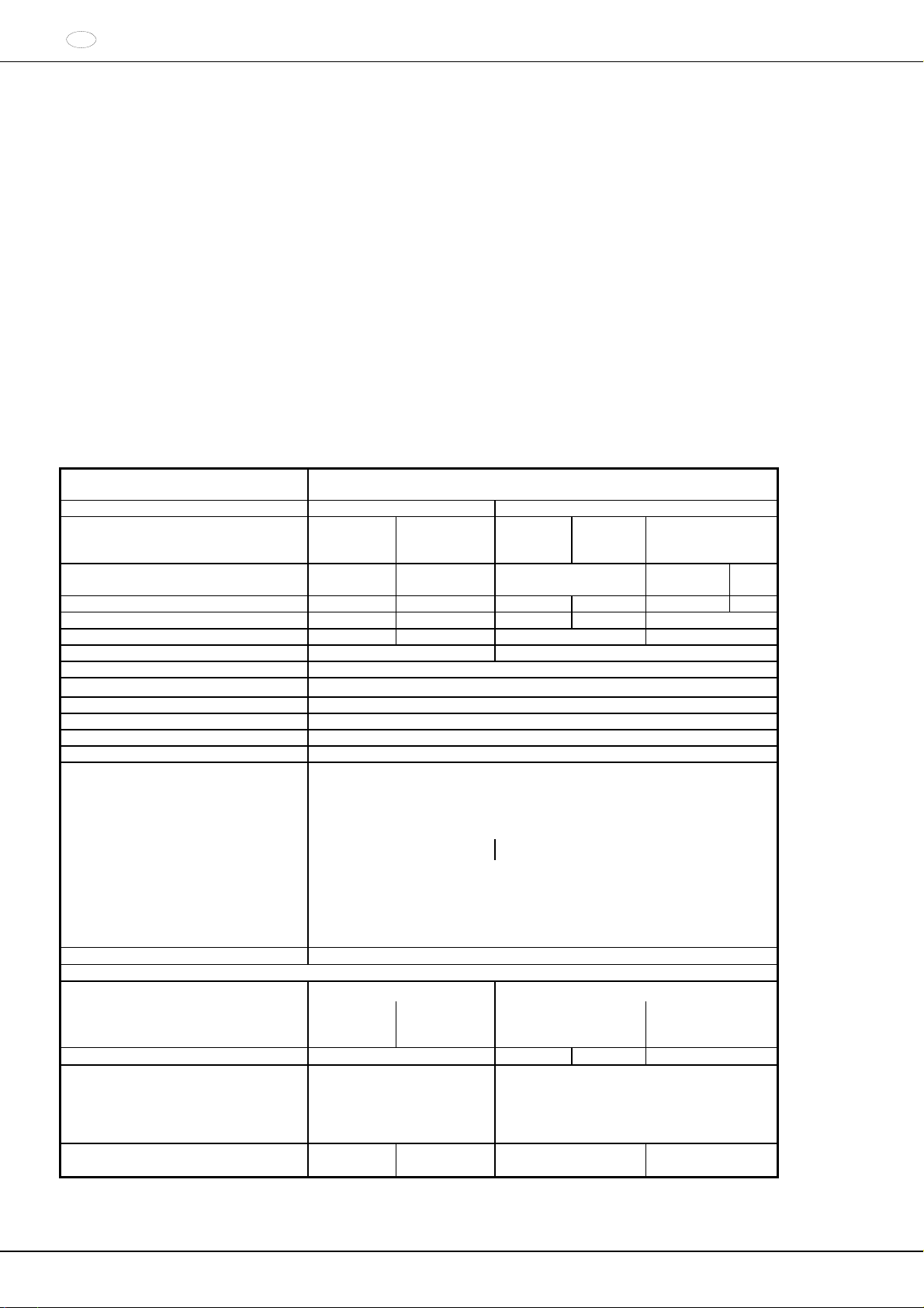
3 Technische Daten
Hersteller
Modell ROTINA 420 ROTINA 420 R
Typ 4701 4701-01
Netzspannung ( 10%)
Netzfrequenz 50 – 60 Hz 50 – 60 Hz 50 Hz 60 Hz 60 Hz 50 Hz
Anschlusswert 870 VA 900 VA 1600 VA 1300 VA 1850 VA
Stromaufnahme 4.3 A 9.0 A 7.5 A 16.0 A
Kältemittel ---- R 404A
Kapazität max. 4 x 600 ml
zulässige Dichte
Drehzahl (RPM) 15000
Beschleunigung (RCF) 24400
Kinetische Energie 24000 Nm
Prüfpflicht (BGR 500) ja
Umgebungsbedingungen
(EN / IEC 61010-1)
Aufstellungsort
Höhe
Umgebungstemperatur
Luftfeuchtigkeit
Überspannungskategorie
(IEC 60364-4-443)
Verschmutzungsgrad
Geräteschutzklasse
nicht für den Einsatz in explosionsgefährdeter Umgebung geeignet.
EMV
Störaussendung, Störfestigkeit
Geräuschpegel (rotorabhängig)
Abmessungen
Breite
Tiefe
Höhe
Gewicht ca. 75 kg ca. 84 kg
200 – 240 V
1
2°C bis 35°C 5°C bis 35°C
maximale relative Luftfeuchte 80% für Temperaturen bis 31°C, linear
abnehmend bis 50% relativer Luftfeuchte bei 40°C.
EN / IEC
61326-1,
Klasse B
63 dB(A) 58 dB(A) 64 dB(A) 58 dB(A)
506 mm 713 mm
650 mm 654 mm
423 mm 423 mm
Andreas Hettich GmbH & Co. KG
D-78532 Tuttlingen
4706,
4706-20,
4706-50
100 – 127 V
1
nur in Innenräumen
bis zu 2000 m über Normal-Null
FCC Class B EN / IEC 61326-1,
200 – 240 V
1.2 kg/dm
4706-07 4706-01
1
3
2
Klasse B
ca. 107.5 kg,
(4706-50)
109 kg
100 – 127V
1
FCC Class B
ca. 117 kg
100 V
1
12/178
4 Sicherheitshinweise
Werden nicht alle Hinweise in dieser Bedienungsanleitung befolgt, kann beim Hersteller kein
Gewährleistungsanspruch geltend gemacht werden.
Die Zentrifuge ist so aufzustellen, dass sie standsicher betrieben werden kann.
Vor Benutzung der Zentrifuge unbedingt den Rotor auf festen Sitz prüfen.
Während eines Zentrifugationslaufes dürfen sich gemäß EN / IEC 61010-2-020, in einem
Sicherheitsbereich von 300 mm um die Zentrifuge herum, keine Personen, Gefahrstoffe und
Gegenstände befinden.
Rotoren, Gehänge und Zubehörteile, die starke Korrosionsspuren oder mechanische Schäden
aufweisen, oder deren Verwendungsdauer abgelaufen ist, dürfen nicht mehr verwendet werden.
Die Zentrifuge darf nicht mehr in Betrieb genommen werden, wenn der Schleuderraum
sicherheitsrelevante Schäden aufweist.
Bei Ausschwingrotoren müssen die Tragzapfen regelmäßig gefettet werden (Hettich-Schmierfett
Nr. 4051), um ein gleichmäßiges Ausschwingen der Gehänge zu gewährleisten.
Bei Zentrifugen ohne Temperaturregelung kann es bei erhöhter Raumtemperatur und/oder bei
häufigem Gebrauch des Gerätes zur Erwärmung des Schleuderraums kommen. Eine
temperaturbedingte Veränderung des Probenmaterials kann deshalb nicht ausgeschlossen
werden.
DE
Vor Inbetriebnahme der Zentrifuge ist die Bedienungsanleitung zu lesen und zu beachten. Nur Personen,
die die Bedienungsanleitung gelesen und verstand en haben, dürfen das Gerät bedienen.
Neben der Bedienungsanleitung und den verbindlichen Regelungen der Unfallverhütung sind auch die
anerkannten fachtechnischen Regeln für sicherheits- und fachgerechtes Arbeiten zu beachten. Die
Bedienungsanleitung ist um Anweisungen aufgrund bestehender nationaler Vorschriften des Verwenderlandes
zur Unfallverhütung und zum Umweltschutz zu ergänzen.
Die Zentrifuge ist nach dem Stand der Technik gebaut und betriebssicher. Es können aber von ihr Gefahren für
den Benutzer oder Dritte ausgehen, wenn sie nicht von geschultem Personal oder unsachgemäß oder zu nicht
bestimmungsgemäßem Gebrauch eingesetzt wird.
Die Zentrifuge darf während des Betriebs nicht bewegt oder angestoßen werden.
Im Störungsfall bzw. bei der Notentriegelung nie in den sich drehenden Rotor greifen.
Um Schäden durch Kondensat zu vermeiden, muss bei Wechsel von einem kalten in einen warmen Raum, die
Zentrifuge entweder mindestens 3 Stunden im warmen Raum aufwärmen bevor sie an das Netz angeschlossen
werden darf oder 30 Minuten im kalten Raum warmlaufen.
Es dürfen nur die vom Hersteller für dieses Gerät zugelassenen Rotoren und das zugelassene Zubehör
verwendet werden (siehe Kapitel "Anhang/Appendix, Rotoren und Zubehör/Rotors and accessories"). Bevor
Zentrifugiergefäße verwendet werden, die nicht in Kapitel "Anhang/Appendix, Rotoren und Zubehör/Rotors and
accessories" aufgeführt sind, hat sich der Benutzer beim Hersteller zu vergewissern, ob diese verwendet werden
dürfen.
Der Rotor der Zentrifuge darf nur entsprechend dem Kapitel "Beladen des Rotors" beladen werden.
3
Bei der Zentrifugation mit maximaler Drehzahl darf die Dichte der Stoffe oder Stoffgemische 1,2 kg/dm
nicht
überschreiten.
Zentrifugationen mit unzulässiger Unwucht sind nicht erlaubt.
Die Zentrifuge darf nicht in explosionsgefährdeter Umgebung betrieben werden.
Eine Zentrifugation mit:
brennbaren oder explosiven Materialien
Materialien, die chemisch mit hoher Energie miteinander reagieren ist verboten.
13/178

DE
Bei der Zentrifugation von gefährlichen Stoffen bzw. Stoffgemischen, die toxisch, radioaktiv oder mit pathogenen
Mikroorganismen verseucht sind, sind durch den Benutzer geeignete Maßnahmen zu treffen.
Es müssen grundsätzlich Zentrifugiergefäße mit speziellen Schraubverschlüssen für gefährliche Substanzen
verwendet werden. Bei Materialien der Risikogruppe 3 und 4 ist zusätzlich zu den verschließbaren
Zentrifugiergefäßen ein Bio-Sicherheitssystem zu verwenden (siehe Handbuch "Laboratory Bio-safety Manual"
der Weltgesundheitsorganisation).
Bei einem Bio-Sicherheitssystem verhindert eine Bioabdichtung (Dichtring) das Austreten von Tröpfchen und
Aerosolen.
Wird das Gehänge eines Bio-Sicherheitssystems ohne den Deckel verwendet, muss der Dichtring vom Gehänge
entfernt werden, um eine Beschädigung des Dichtrings während des Zentrifugationslaufes zu vermeiden.
Beschädigte Dichtringe dürfen nicht mehr zum Abdichten des Bio-Sicherheitssystems verwendet werden.
Ohne Verwendung eines Bio-Sicherheitssystems ist eine Zentrifuge im Sinne der Norm EN / IEC 61010-2-020
nicht mikrobiologisch dicht.
Beim Verschließen eines Bio-Sicherheitssystems sind die Anweisungen in Kapitel "Bio-Sicherheitssysteme
verschließen" zu befolgen.
Lieferbare Bio-Sicherheitssysteme siehe Kapitel "Anhang/Appendix, Rotoren und Zubehör/Rotors and
accessories". Im Zweifelsfall sind entsprechende Informationen beim Hersteller einzuholen.
Der Betrieb der Zentrifuge mit stark korrodierenden Stoffen, welche die mechanische Festigkeit von Rotoren,
Gehängen und Zubehörteilen beeinträchtigen können, ist nicht erlaubt.
Reparaturen dürfen nur von einer vom Hersteller autorisierten Person ausgeführt werden.
Es dürfen nur Originalersatzteile und zugelassenes Originalzubehör der Firma Andreas Hettich GmbH & Co. KG
verwendet werden.
Es gelten die folgenden Sicherheitsbestimmungen:
EN / IEC 61010-1 und EN / IEC 61010-2-020 sowie deren nationalen Abweichungen.
Die Sicherheit und Zuverlässigkeit der Zentrifuge ist nur dann gewährleistet, wenn:
die Zentrifuge nach der Bedienungsanleitung betrieben wird.
die elektrische Installation, am Aufstellungsort der Zentrifuge, den Anforderungen von EN / IEC Festle-
gungen entspricht.
die in den jeweiligen Ländern vorgeschriebenen Prüfungen für die Sicherheit des Gerätes, z. B. in
Deutschland nach BGV A1 und BGR 500, durch einen Sachkundigen durchgeführt werden.
14/178
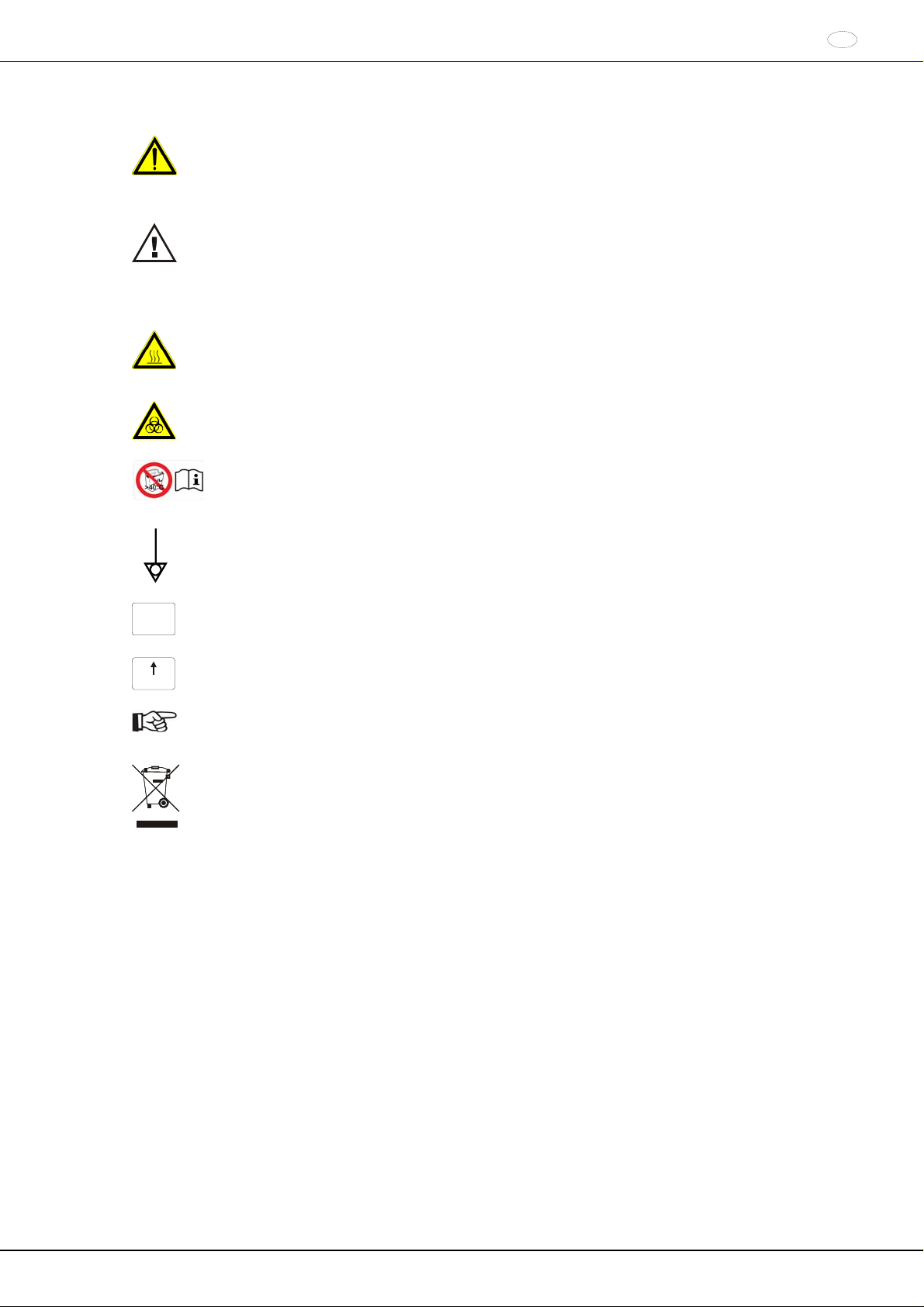
5 Bedeutung der Symbole
Symbol am Gerät:
Achtung, allgemeine Gefahrenstelle.
Vor Benutzung des Gerätes unbedingt die Bedienungsanleitung lesen und die sicherheitsrelevanten
Hinweise beachten!
Symbol in diesem Dokument:
Achtung, allgemeine Gefahrenstelle.
Dieses Symbol kennzeichnet sicherheitsrelevante Hinweise und deutet auf mögliche gefährliche
Situationen hin.
Das Nichtbeachten dieser Hinweise kann zu Sach- und Personenschäden führen.
Symbol am Gerät und in diesem Dokument:
Warnung vor heißer Oberfläche.
Das Nichtbeachten dieses Hinweises kann zu Sach- und Personenschäden führen.
Symbol am Gerät und in diesem Dokument:
Warnung vor Biogefährdung.
Symbol am Gerät und in diesem Dokument:
Kunststoff-Nutgehänge dürfen nur bei Temperaturen bis maximal 40°C / 104°F verwendet werden.
Das Nichtbeachten dieses Hinweises kann zu Sach- und Personenschäden führen.
Symbol am Gerät:
Äquipotential: Steckverbinder (PA-Stecker) für Potentialausgleich (nur bei Zentrifuge mit PA-Stecker).
IOIOI
RS232
Symbol am Gerät:
Schnittstelle RS232 (nur bei Zentrifuge mit Schnittstelle RS232).
Symbol am Gerät:
F2
Sicherungsautomat (nur bei Zentrifuge mit Sicherungsautomat).
Symbol in diesem Dokument:
Dieses Symbol deutet auf wichtige Sachverhalte hin.
Symbol am Gerät und in diesem Dokument:
Symbol für die getrennte Sammlung von Elektro- und Elektronikgeräten, gemäß der Richtlinie
2002/96/EG (WEEE). Das Gerät gehört zur Gruppe 8 (Medizinische Geräte).
Verwendung in den Ländern der Europäischen Union sowie in Norwegen und der Schweiz.
DE
15/178
DE
6 Lieferumfang
1 Anschlusskabel
1 Sechskant-Stiftschlüssel 2,5 mm
1 Sechskant-Stiftschlüssel 5 mm
1 Schmierfett für Tragzapfen
1 Bedienungsanleitung
1 Hinweisblatt Transportsicherung
Rotor(en) und das entsprechende Zubehör werden je nach Bestellung mitgeliefert.
7 Auspacken der Zentrifuge
Den Karton nach oben abheben und die Polsterung entfernen.
Die Zentrifuge, mit der angemessenen Anzahl von Helfern, an beiden Seiten anheben und auf den Labortisch
stellen.
8 Inbetriebnahme
Gemäß der Laborgerätenorm EN / IEC 61010-2-020 muss in der Gebäudeinstallation ein Notausschalter zur
Trennung der Netzversorgung im Fehlerfall angebracht sein.
Dieser Schalter muss abseits der Zentrifuge angebracht sein, vorzugsweise außerhalb des Raumes, in dem sich
die Zentrifuge befindet, oder neben dem Ausgang dieses Raumes.
Die Zentrifuge an einem geeigneten Platz standsicher aufstellen und nivellieren. Bei der Aufstellung ist
der geforderte Sicherheitsbereich gemäß EN / IEC 61010-2-020, von 300 mm um die Zentrifuge herum,
einzuhalten.
Nicht an der Frontblende anheben.
Das Gewicht der Zentrifuge beachten, siehe Kapitel "Technische Daten".
Während eines Zentrifugationslaufes dürfen sich gemäß EN / IEC 61010-2-020, in einem
Sicherheitsbereich von 300 mm um die Zentrifuge herum, keine Personen, Gefahrstoffe und
Gegenstände befinden.
Lüftungsöffnungen dürfen nicht zugestellt werden.
Es muss ein Lüftungsabstand von 300 mm um die Lüftungsschlitze oder Lüftungsöffnungen eingehalten werden.
Bei der Zentrifuge, Best.-Nr. 4706-20, die Stickstoffversorgung gemäß dem beigefügten Hinweisblatt
AH4706-20XX anschließen.
Das Anschließen der Zentrifuge muss unbedingt gemäß dem beigefügten Hinweisblatt erfolgen.
Das beigefügte Hinweisblatt unbedingt beachten.
Zentrifuge mit PA-Stecker:
Bei Bedarf den PA-Stecker an der Rückseite des Gerätes mit einem zusätzlichen medizinischen PotentialAusgleich-System verbinden.
Zentrifuge mit Schnittstelle RS232:
Die Schnittstelle RS232 der Zentrifuge mit einem RS232-Verbindungskabel (nicht im Lieferumfang enthalten) an
den PC anschließen.
Prüfen ob die Netzspannung mit der Angabe auf dem Typenschild übereinstimmt.
Die Zentrifuge mit dem Anschlusskabel an eine genormte Netzsteckdose anschließen. Anschlusswert siehe
Kapitel "Technische Daten".
Den Netzschalter einschalten (Schalterstellung ""). Die LED's in den Tasten blinken.
Nacheinander erscheinen folgende Anzeigen:
1. das Zentrifugen-Modell
2. die Programmversion
3. der Rotorcode (Rotor), die maximale Drehzahl des Rotors (Nmax) und der voreingestellte Zentrifugierradius
(R) des zuletzt durch die Rotorerkennung erkannten Rotors.
4. OPEN OEFFNEN
Den Deckel öffnen.
Die Zentrifugations-Daten des zuletzt benutzten Programms oder des Programms 1 werden angezeigt
Die Transportsicherung entfernen, siehe Hinweisblatt "Transportsicherung".
16/178
9 Schnittstelle (nur bei Zentrifuge mit Schnittstelle)
Optional kann das Gerät mit einer Schnittstelle RS232 ausgerüstet werden.
IOIOI
Die Schnittstelle RS232 ist mit dem Symbol
RS232
gekennzeichnet.
Über diese Schnittstelle kann die Zentrifuge gesteuert und Daten abgefragt werden.
Die LED in der Taste
PROG
leuchtet während der Datenkommunikation.
10 Deckel öffnen und schließen
10.1 Deckel öffnen
Der Deckel lässt sich nur öffnen, wenn die Zentrifuge eingeschaltet ist und der Rotor stillsteht.
Sollte dies nicht möglich sein, siehe Kapitel "Notentriegelung".
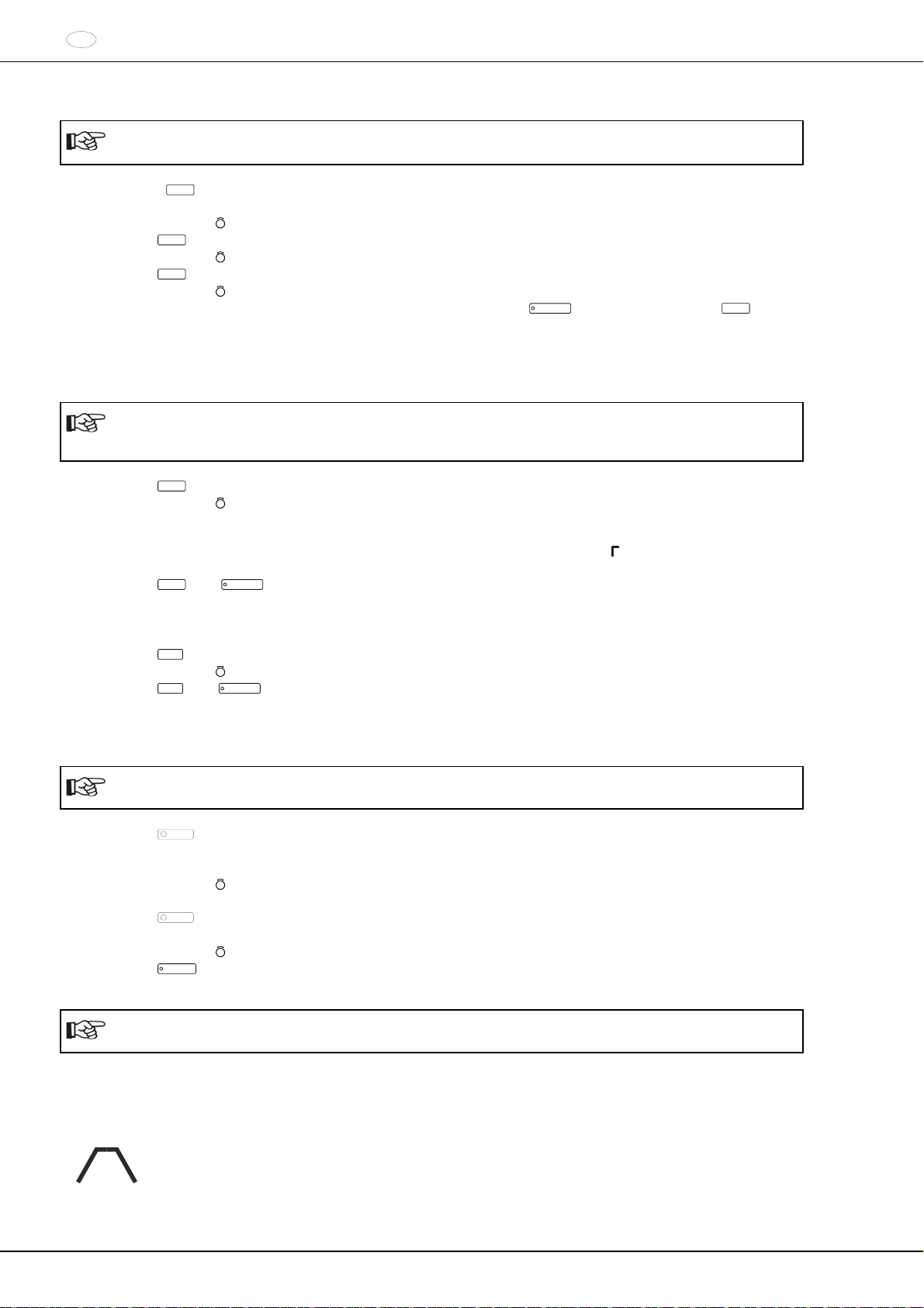
Die Taste
OPEN / STOP
drücken. Der Deckel entriegelt motorisch und die linke LED in der Taste
OPEN / STOP
erlischt.
10.2 Deckel schließen
Mit den Fingern nicht zwischen Deckel und Gehäuse greifen.
Den Deckel nicht zuschlagen.
Wenn die linke LED in der Taste
OPEN / STOP
blinkt, die Taste
OPEN / STOP
drücken, dass die motorische
Deckelverriegelung die Grundstellung (geöffnet) einnimmt.
Den Deckel auflegen und die Deckelvorderkante leicht niederdrücken. Die Verriegelung erfolgt motorisch. Die
linke LED in der Taste
OPEN / STOP
leuchtet auf.
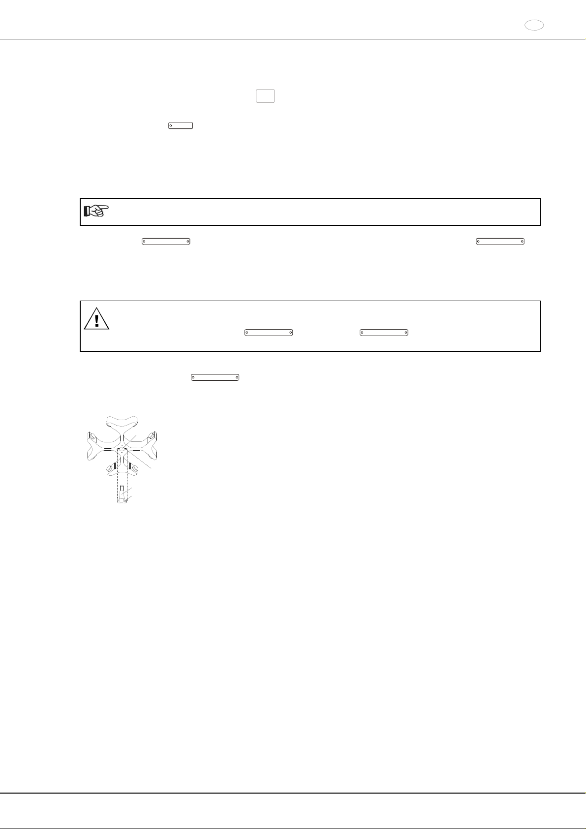
11 Ein- und Ausbau des Rotors
Die Motorwelle (C) und die Bohrung des Rotors (A) reinigen und anschließend die
A
Motorwelle leicht einfetten. Schmutzpartikel zwischen der Motorwelle und dem Rotor
verhindern einen einwandfreien Sitz des Rotors und verursachen einen unruhigen Lauf.
Den Rotor vertikal auf die Motorwelle aufsetzen. Der Mitnehmer der Motorwelle (D)
muss sich in der Nut des Rotors (B) befinden. Auf dem Rotor ist die Ausrichtung der Nut
B
gekennzeichnet.
C
D
Die Spannmutter des Rotors mit dem mitgelieferten Schlüssel durch Drehen im
Uhrzeigersinn anziehen.
Den Rotor auf festen Sitz prüfen.
Lösen des Rotors: Die Spannmutter durch Drehen entgegen dem Uhrzeigersinn lösen
und bis zum Abhebe-Druckpunkt drehen. Nach Überwindung des Abhebe-Druckpunkts
löst sich der Rotor vom Konus der Motorwelle. Die Spannmutter drehen, bis sich der
Rotor von der Motorwelle abheben lässt.
DE
17/178
DE
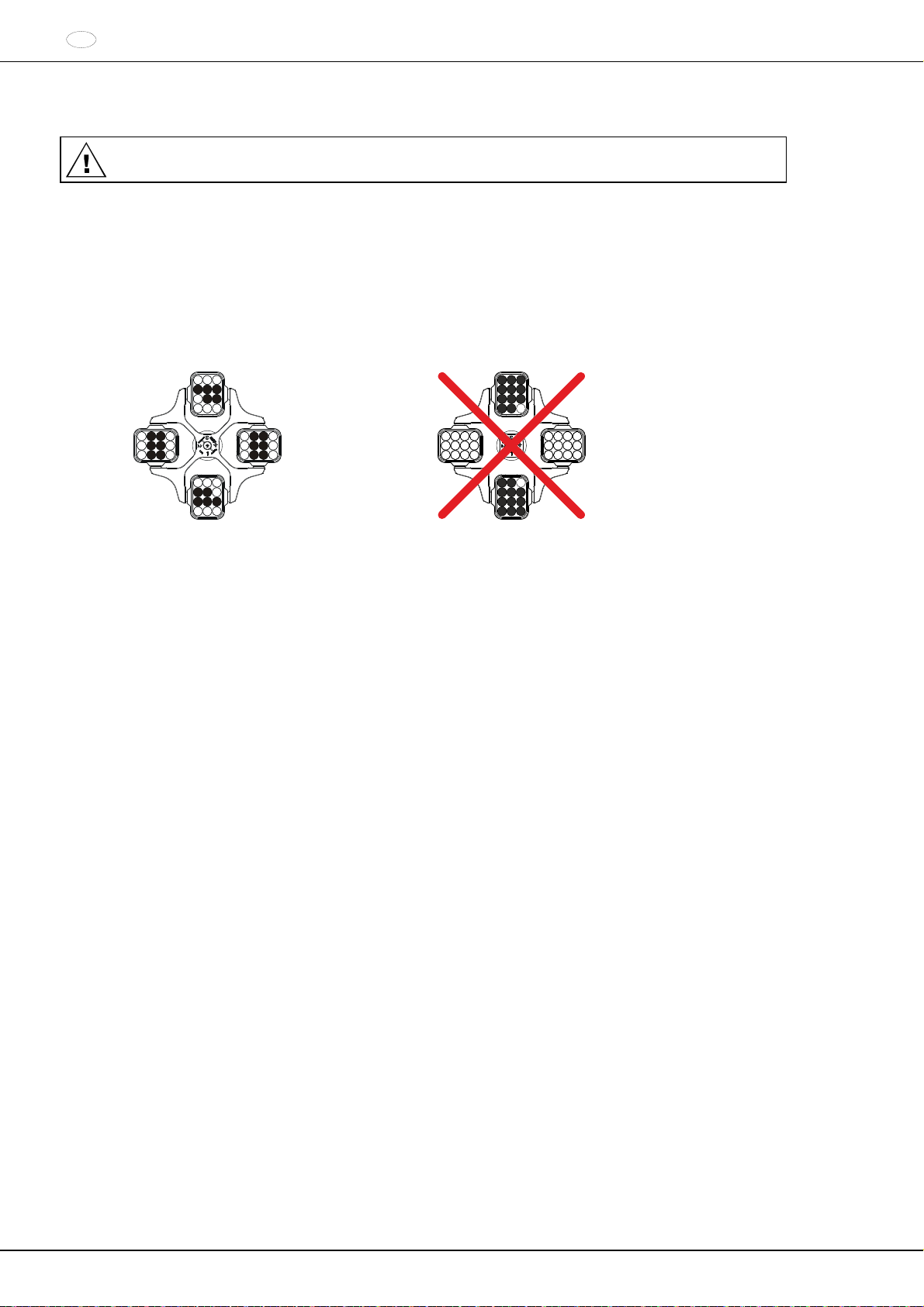
12 Beladen des Rotors
Standard-Zentrifugiergefäße aus Glas sind belastbar bis RZB 4000 (DIN 58970 Teil 2).
Den Rotor auf festen Sitz prüfen.
Bei Ausschwingrotoren müssen alle Plätze des Rotors mit gleichen Gehängen besetzt sein. Bestimmte
Gehänge sind mit der Nummer des Rotorplatzes gekennzeichnet. Diese Gehänge dürfen nur in den
entsprechenden Platz des Rotors eingesetzt werden.
Gehänge die mit einer Set-Nummer gekennzeichnet sind, z. B. S001/4, dürfen nur im Set verwendet werden.
Die Rotoren und Gehänge dürfen nur symmetrisch beladen werden. Die Zentrifugiergefäße müssen gleichmäßig
auf alle Plätze des Rotors verteilt werden. Zugelassene Kombinationen siehe Kapitel "Anhang/Appendix,
Rotoren und Zubehör/Rotors and accessories".
Bei Winkelrotoren müssen alle möglichen Plätze des Rotors beladen werden, siehe Kapitel "Anhang/Appendix,
Rotoren und Zubehör/Rotors and accessories".
Rotor ist gleichmäßig beladen
Nicht zulässig!
Rotor ist ungleichmäßig beladen
Auf bestimmten Gehängen ist das Gewicht der maximalen Beladung oder das Gewicht der maximalen Beladung
und das maximale Gewicht des komplett bestückten Gehänges angegeben. Diese Gewichte dürfen nicht
überschritten werden. Im Ausnahmefall siehe Kapitel "Zentrifugation von Stoffen oder Stoffgemischen mit einer
höheren Dichte als 1,2 kg/dm
3
". Die Gewichtsangabe der maximalen Beladung umfasst das Gesamtgewicht von
Reduzierung, Gestell, Zentrifugiergefäß und Inhalt.
Bei Behältern mit Gummieinlagen muss sich unter den Zentrifugiergefäßen immer die gleiche Anzahl von
Gummieinlagen befinden.
Die Zentrifugiergefäße immer außerhalb der Zentrifuge befüllen.
Es darf beim Füllen und beim Ausschwingen der Gehänge keine Flüssigkeit in den Schleuderraum gelangen.
Die vom Hersteller angegebene maximale Füllmenge der Zentrifugiergefäße darf nicht überschritten werden.
Um die Gewichtsunterschiede innerhalb der Zentrifugiergefäße möglichst gering zu halten, ist auf eine
gleichmäßige Füllhöhe in den Gefäßen zu achten.
18/178
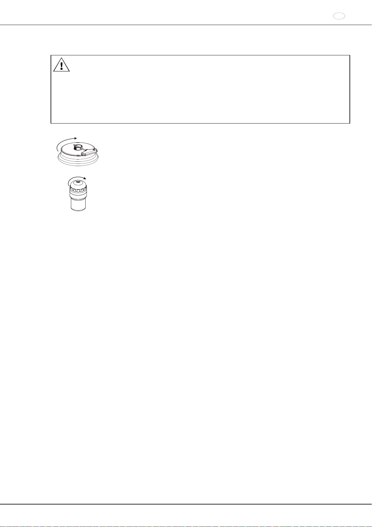
13 Verschließen von Bio-Sicherheitssystemen
Um Dichtigkeit zu gewährleisten, muss der Deckel eines Bio-Sicherheitssystems fest verschlossen werden.
Um ein Verdrehen des Dichtungsringes während dem Öffnen und Schließen des Deckels zu vermeiden, muss
der Dichtungsring mit Talkum-Puder oder einem Gummi-Pflegemittel leicht eingerieben werden.
Wird das Gehänge eines Bio-Sicherheitssystems ohne den Deckel verwendet, muss der Dichtring vom
Gehänge entfernt werden, um eine Beschädigung des Dichtrings während des Zentrifugationslaufes zu
vermeiden. Beschädigte Dichtringe dürfen nicht mehr zum Abdichten des Bio-Sicherheitssystems verwendet
werden.
Lieferbare Bio-Sicherheitssysteme siehe Kapitel "Anhang/Appendix, Rotoren und Zubehör/Rotors and
accessories". Im Zweifelsfall sind entsprechende Informationen beim Hersteller einzuholen.
Deckel mit Schraubverschluss und Bohrung im Drehgriff:
Den mitgelieferten Schlüssel durch die Bohrung im Drehgriff stecken und durch Drehen im
Uhrzeigersinn den Deckel fest verschließen.
Deckel mit Schraubverschluss:
Den Deckel von Hand, durch Drehen im Uhrzeigersinn, fest verschließen.
DE
19/178
DE
t
t
14 Bedien- und Anzeigeelemente
Siehe Abbildung auf Seite 2.
Fig. 2: Anzeige- und Bedienfeld
14.1 Drehknopf
Zum Einstellen der einzelnen Parameter.
Drehen entgegen dem Uhrzeigersinn erniedrigt den Wert. Drehen im Uhrzeigersinn erhöht den Wert.
14.2 Tasten und Einstellmöglichkeiten
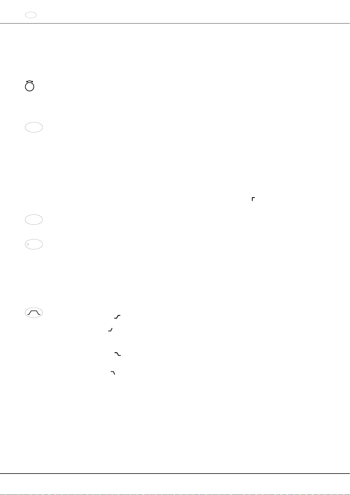
TIME
Laufzeit, Parameter t/hms.
h: Stunden. Einstellbar von 1 h bis 99 h, in 1 Stunden-Schritten.
m: Minuten. Einstellbar von 1 min bis 59 min, in 1 Minuten-Schritten.
s: Sekunden. Einstellbar von 1 s bis 59 s, in 1 Sekunden-Schritten.
Dauerlauf ""
Beginn der Zählung der Laufzeit einstellen. Die Einstellung ist nur möglich, wenn die Funktion "Dual time
mode" aktiviert ist, siehe Kapitel Funktion "Dual time mode" aktivieren oder deaktivieren". Die Funktion ist
ab Werk deaktiviert.
Es kann eingestellt werden, ob die Laufzeit sofort nach Start des Zentrifugationslaufes, oder erst nach
Erreichen der eingestellten Drehzahl, zu zählen beginnt.
Timing begins at Start: Die Laufzeit beginnt sofort nach Start des Zentrifugationslaufes zu zählen.
Timing begins at Speed: Die Laufzeit beginnt erst nach Erreichen der eingestellten Drehzahl zu zählen.
Ist Timing begins at Speed eingestellt, wird dies in der Anzeige durch das Symbol
Zeit, angezeigt.
RPM
Drehzahl, Parameter RPM.
Einstellbar von 50 RPM bis zur maximalen Drehzahl des Rotors (Nmax), in 10er Schritten. Maximale
Drehzahl des Rotors siehe Kapitel "Anhang/Appendix, Rotoren und Zubehör/Rotors and accessories“.
RCF
Relative Zentrifugalbeschleunigung, Parameter RCF.
Die RCF wird in Klammern angezeigt. Die LED in der Taste leuchtet.
Einstellbar ist ein Zahlenwert, der eine Drehzahl zwischen 50 RPM und der maximalen Drehzahl des
Rotors (Nmax) ergibt. Einstellbar in 1er Schritten.
Zentrifugierradius, Parameter RAD.
Einstellbar von 10 mm bis 330 mm, in 1 Millimeter-Schritten. Zentrifugierradius siehe Kapitel
"Anhang/Appendix, Rotoren und Zubehör/Rotors and accessories".
Abfrage des Integral RCF.
Die Abfrage des Integral RCF ist nur möglich, wenn die Anzeige des Integral RCF aktiviert ist, siehe
Kapitel "Anzeige des Integral RCF aktivieren oder deaktivieren".
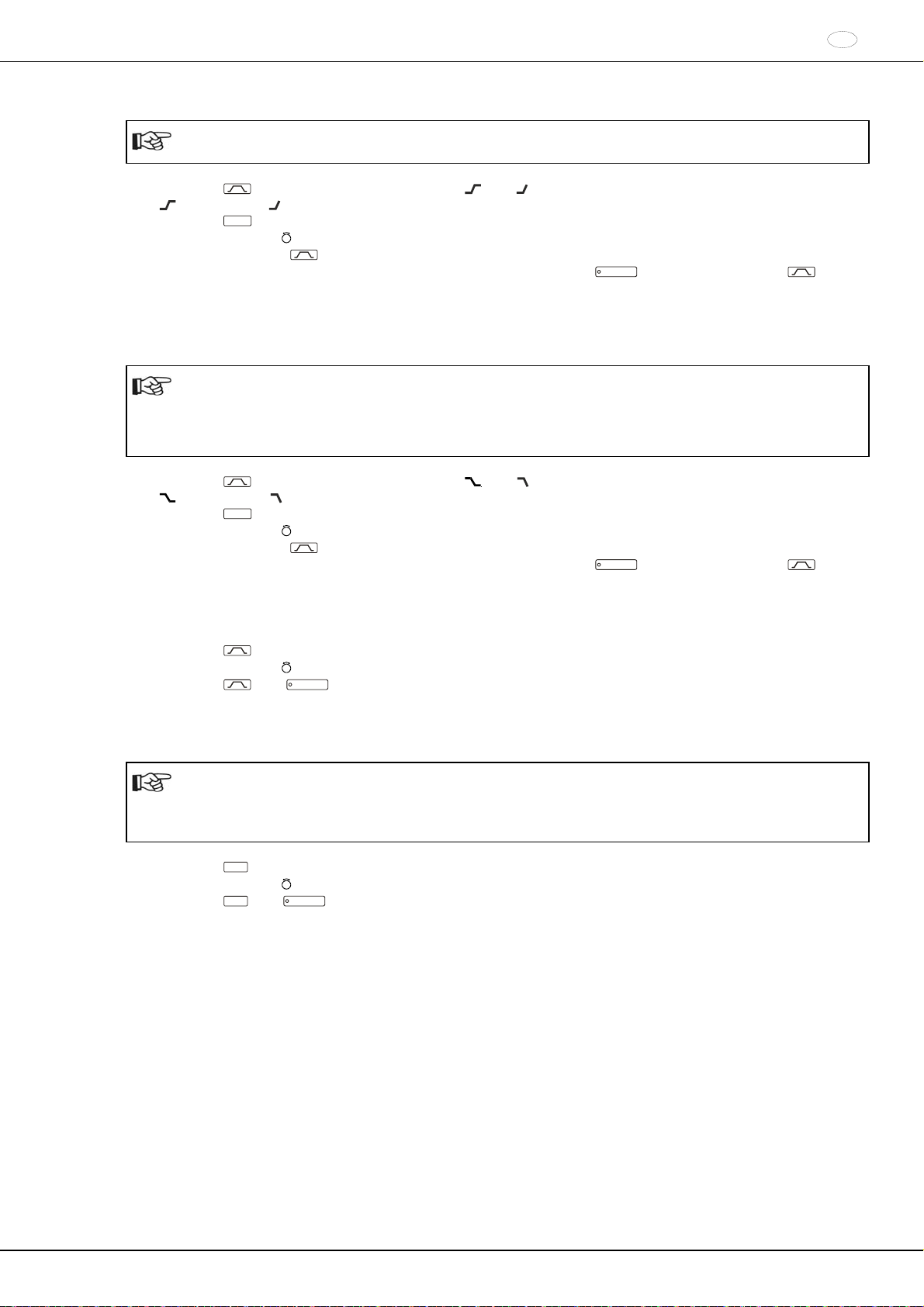
An- und Auslauf-Parameter
Anlaufstufen, Parameter
.
Stufe 9 = kürzeste Anlaufzeit, ... Stufe 1 = längste Anlaufzeit.
Anlaufzeit, Parameter
. Einstellbar in 1 Sekunden-Schritten. Der einstellbare Zeitbereich ist von der
eingestellten Drehzahl abhängig.
Das Einstellen von Anlaufzeiten ist nur möglich, wenn diese aktiviert sind, siehe Kapitel "An- und
Auslaufzeiten aktivieren oder deaktivieren".
Bremsstufen, Parameter
1-9 = Lineare Bremskurve,.
Stufe 9, = kürzeste Auslaufzeit, ... Stufe 1, = lange Auslaufzeit, Stufe 0 = ungebremster Auslauf.
Auslaufzeit, Parameter
. Einstellbar in 1 Sekunden-Schritten. Der einstellbare Zeitbereich ist von der
eingestellten Drehzahl abhängig.
Das Einstellen von Auslaufzeiten ist nur möglich, wenn diese aktiviert sind, siehe Kapitel "An- und
Auslaufzeiten aktivieren oder deaktivieren".
Bremsabschaltungs-Drehzahl, Parameter N Brake.
Einstellbar von 50 RPM bis zur maximalen Drehzahl des Rotors (Nmax), in 10er Schritten.
Nach Erreichen dieser Drehzahl erfolgt der ungebremste Auslauf.
, links neben der
20/178
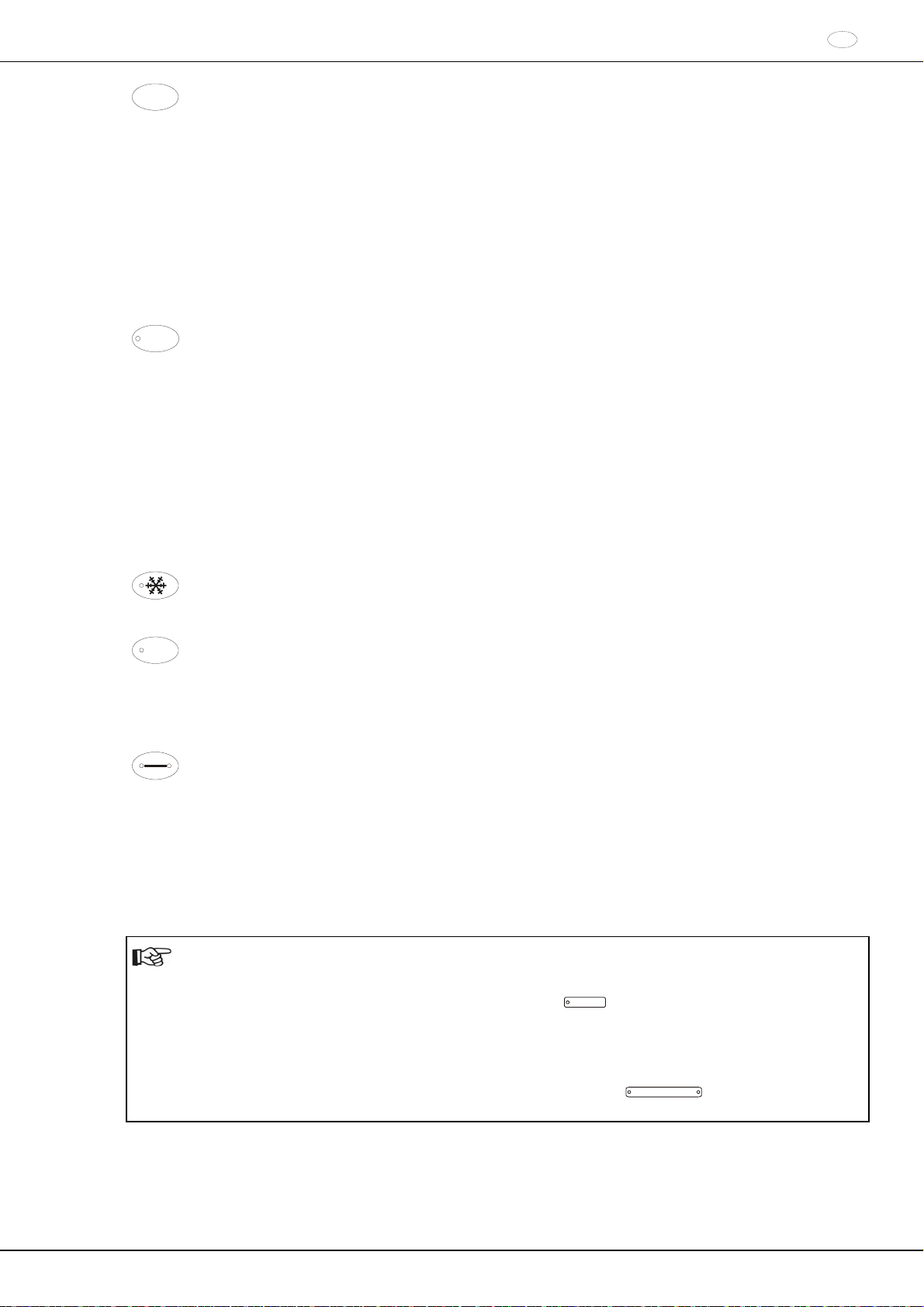
Temperatur (nur bei Zentrifuge mit Kühlung)
T/°C
Einstellbar in Grad Celsius (°C) oder in Grad Fahrenheit (°F). Einstellung der Temperatur-Einheit, siehe
Kapitel "Temperatur-Einheit einstellen".
Parameter T/°C = Grad Celsius (°C).
Einstellbar von -20°C bis +40°C, in 1°C-Schritten (bei Option Heizen/Kühlen von -20°C bis +90°C
einstellbar).
Parameter T/°F = Grad Fahrenheit (°F).
Einstellbar von -4°F bis +104°F, in 1°F-Schritten (bei Option Heizen/Kühlen von -4°F bis +194°F
einstellbar).
Die tiefste erreichbare Temperatur ist rotorabhängig (siehe Kapitel "Anhang/Appendix, Rotoren und
Zubehör/Rotors and accessories").
Heizung aktivieren oder deaktivieren, Parameter Heater on/off (nur bei Option Heizen/Kühlen).
In den Menüs rückwärts blättern.
PROG
Programme und Programmverknüpfungen abrufen, Parameter RCL.
Programme: Programmplätze 1 bis 99 und PREC. Programmverknüpfungen: Programmplätze A bis Z.
Programme und Programmverknüpfungen speichern, Parameter STO.
Es können 99 Programme gespeichert werden (bei Zentrifuge ohne Kühlung: Programmplätze 1 bis 99,
bei Zentrifuge mit Kühlung: Programmplätze 1 bis 98 und PREC). Der Programmplatz PREC
(PRECOOLING) ist für das Vorkühlprogramm reserviert. Der Programmplatz 0 dient als Zwischenspeicher, für die Zentrifugations-Daten des zuletzt erfolgten Zentrifugationslaufes. Auf diesem Programmplatz können keine Programme gespeichert werden.
Es können 25 Programmverknüpfungen gespeichert werden (Programmplätze A bis Z, Programmplatz J
gibt es nicht). Eine Programmverknüpfung kann aus 20 Programmen bestehen.
Programme verknüpfen, Parameter EDIT.
Das "Machine Menu" aufrufen (die Taste 8 Sekunden gedrückt halten).
Im "Machine Menu" die Menüs "Info", "Operating Time" und "Settings" auswählen.
In den Menüs vorwärts blättern.
Vorkühlung des Rotors starten (nur bei Zentrifuge mit Kühlung). Die LED in der Taste leuchtet während
des Zentrifugationslaufes, solange sich der Rotor dreht.
Die Vorkühlung des Rotors erfolgt automatisch mit Programm PREC (PRECOOLING).
START
Zentrifugationslauf starten. Die LED in der Taste leuchtet während des Zentrifugationslaufes, solange sich
der Rotor dreht.
Kurzzeitzentrifugation.
Der Zentrifugationslauf erfolgt, solange die Taste gedrückt gehalten wird. Die LED in der Taste leuchtet
während des Zentrifugationslaufes, solange sich der Rotor dreht.
Die Menüs "Info", "Operating Time" und "Settings" aufrufen.
STOP
OPEN
Zentrifugationslauf beenden.
Der Rotor läuft mit dem vorgewählten Auslauf-Parameter aus. Die rechte LED in der Taste leuchtet bis der
Rotor stillsteht. Nach Stillstand des Rotors blinkt die linke LED in der Taste.
Zweimaliges Drücken der Taste löst den NOT-STOP aus.
Den Deckel entriegeln.
Die linke LED in der Taste erlischt.
Die Parametereingabe und die Menüs verlassen.
15 Zentrifugations–Parameter eingeben
Wird nach der Anwahl oder während der Eingabe von Parametern 8 Sekunden lang keine Taste gedrückt,
werden in der Anzeige wieder die vorherigen Werte angezeigt. Die Eingabe der Parameter muss dann erneut
durchgeführt werden.
Bei Eingabe von mehreren Parametern muss die Taste
Parameters gedrückt werden.
Werden Parameter verändert, wird die Programmplatz-Nummer in Klammern () angezeigt. Dies bedeutet,
dass die Zentrifugations-Daten in der Anzeige nicht mehr mit den gespeicherten Zentrifugations-Daten des
Programmplatzes übereinstimmen.
Die Eingabe der Parameter kann jederzeit durch Drücken der Taste
diesem Fall werden die Einstellungen nicht gespeichert.
START
erst nach der Einstellung des letzten
OPEN / STOP
abgebrochen werden. In
DE
21/178
DE
15.1 Laufzeit
Um den Dauerlauf einzustellen müssen die Minuten, Sekunden und Stunden auf Null gestellt werden.
Der Dauerlauf wird in der Anzeige durch das Symbol "" angezeigt.
Die Taste
TIME
drücken. Der Parameter t/hms wird angezeigt. Die Minuten (m) werden in Klammern
dargestellt, und können verändert werden.
Mit dem Drehknopf
Die Taste
TIME
Mit dem Drehknopf
Die Taste
TIME
Mit dem Drehknopf
Um die Einstellung in die Anzeige zu übernehmen entweder die Taste
den gewünschten Wert einstellen.
drücken. Die Sekunden (s) werden in Klammern dargestellt, und können verändert werden.
den gewünschten Wert einstellen.
drücken. Die Stunden (h) werden in Klammern dargestellt, und können verändert werden.
den gewünschten Wert einstellen.
START
drücken oder die Taste
drücken, bis wieder die Zentrifugations-Daten angezeigt werden.
15.2 Beginn der Zählung der Laufzeit
Der Beginn der Zählung der Laufzeit kann nur eingestellt werden, wenn die Funktion "Dual time mode"
aktiviert ist, siehe Kapitel Funktion "Dual time mode" aktivieren oder deaktivieren". Die Funktion ist ab Werk
deaktiviert.
Die Taste
Mit dem Drehknopf
TIME
so oft drücken, bis Timing begins at Start bzw. Timing begins at Speed angezeigt wird.
Timing begins at Start oder Timing begins at Speed einstellen.
Timing begins at Start = Die Laufzeit beginnt sofort nach Start des Zentrifugationslaufes zu zählen.
Timing begins at Speed = Die Laufzeit beginnt erst nach Erreichen der eingestellten Drehzahl zu zählen.
Ist Timing begins at Speed eingestellt, wird dies in der Anzeige durch das Symbol
, links neben der Zeit,
angezeigt.
Die Taste
TIME
oder
START
drücken, um die Einstellung in die Anzeige zu übernehmen.
15.3 Drehzahl (RPM)
RPM
Die Taste
Mit dem Drehknopf
Die Taste
drücken. Der Parameter RPM wird angezeigt.
den gewünschten Wert einstellen.
RPM
oder
START
drücken, um die Einstellung in die Anzeige zu übernehmen.
15.4 Relative Zentrifugalbeschleunigung (RCF) und Zentrifugierradius (RAD)
Die relative Zentrifugalbeschleunigung (RCF) ist vom Zentrifugierradius (RAD) abhängig. Vor dem Einstellen
der RCF muss der Zentrifugierradius eingestellt werden.
RCF
Die Taste
so oft drücken, bis die Parameter RAD und RCF angezeigt werden, und der Wert des
Parameters RAD in Klammern angezeigt wird, z. B. RAD = 146 RCF = 3695. Die LED in der Taste
leuchtet.
Mit dem Drehknopf den gewünschten Zentrifugierradius einstellen.
Durch Verändern des Zentrifugierradius passt sich der Wert der RCF automatisch an.
Die Taste
RCF
nochmals drücken. Der Wert des Parameters RCF wird in Klammern angezeigt, z. B. RAD =
146 RCF = 3695.
Mit dem Drehknopf
Die Taste
PROG
die gewünschte RCF einstellen.
drücken, um den eingestellten RCF-Wert zu speichern, siehe Kapitel "Programme eingeben
oder ändern".
Erst durch Speichern (STO) des eingestellten RCF-Werts wird der daraus resultierende RPM-Wert
übernommen.
15.5 An- und Auslauf-Parameter
Die eingestellten An- und Auslauf-Parameter werden angezeigt.
x: 1-9 = Anlaufstufe, t = Anlaufzeit
y
x
y: 1-9 = Bremsstufe, 0 = ungebremster Auslauf, t = Auslaufzeit
TIME
so oft
22/178
15.5.1 Anlaufstufe und Anlaufzeit
Das Einstellen von Anlaufzeiten ist nur möglich, wenn diese aktiviert sind, siehe Kapitel "An- und
Auslaufzeiten aktivieren oder deaktivieren".
Die Taste so oft drücken, bis der Parameter oder t angezeigt wird.
= Anlaufstufe, t = Anlaufzeit
TIME
Die Taste
Mit dem Drehknopf
drücken, um zwischen der Anlaufstufe und der Anlaufzeit umzuschalten.
die gewünschte Stufe oder Zeit einstellen.
Bei Bedarf die Taste drücken, um den nächsten Parameter einzustellen.
Um die Einstellung in die Anzeige zu übernehmen entweder die Taste
START
drücken, bis wieder die Zentrifugations-Daten angezeigt werden.
15.5.2 Bremsstufe und Auslaufzeit
Bei diesem Gerät können keine B-Bremsstufen eingestellt werden. Die Aktivierung der B-Bremsstufen im
Menü "Settings" ist nicht möglich (Parameter B-Ramp = off). B-Bremsstufen sind ähnlich einer exponentiellen
Bremskurve.
Das Einstellen von Auslaufzeiten ist nur möglich, wenn diese aktiviert sind, siehe Kapitel "An- und
Auslaufzeiten aktivieren oder deaktivieren".
Die Taste so oft drücken, bis der Parameter oder t angezeigt wird.
= Bremsstufe, t = Auslaufzeit
Die Taste
Mit dem Drehknopf
TIME
drücken, um zwischen der Bremsstufe und der Auslaufzeit umzuschalten.
die gewünschte Stufe oder Zeit einstellen.
Bei Bedarf die Taste drücken, um den nächsten Parameter einzustellen.
Um die Einstellung in die Anzeige zu übernehmen entweder die Taste
START
drücken, bis wieder die Zentrifugations-Daten angezeigt werden.
15.5.3 Bremsabschaltungs-Drehzahl
Die Taste
so oft drücken, bis der Parameter N Brake angezeigt wird.
Mit dem Drehknopf den gewünschten Wert einstellen.
Die Taste oder
START
drücken, um die Einstellung in die Anzeige zu übernehmen.
15.6 Temperatur (nur bei Zentrifuge mit Kühlung)
Die Temperatur kann in Grad Celsius (°C) oder in Grad Fahrenheit (°F) eingegeben werden. Einstellung der
Temperatur-Einheit siehe Kapitel "Temperatur-Einheit einstellen".
Ist als Temperatur-Einheit Grad Fahrenheit (°F) eingestellt, erscheint in der Anzeige hinter dem
Temperaturwert der Buchstabe "F".
T/°C
Die Taste
Mit dem Drehknopf
Die Taste
drücken. Der Parameter T/°C bzw. T/°F wird angezeigt.
den gewünschten Wert einstellen.
T/°C
oder
START
drücken, um die Einstellung in die Anzeige zu übernehmen.
DE
drücken oder die Taste so oft
drücken oder die Taste so oft
23/178
DE
16 Programmierung
Werden Parameter verändert, wird die Programmplatz-Nummer in Klammern () angezeigt. Dies bedeutet,
dass die Zentrifugations-Daten in der Anzeige nicht mehr mit den gespeicherten Zentrifugations-Daten des
Programmplatzes übereinstimmen.
16.1 Programme eingeben oder ändern
Die gewünschten Parameter einstellen (siehe Kapitel "Zentrifugations-Parameter eingeben").
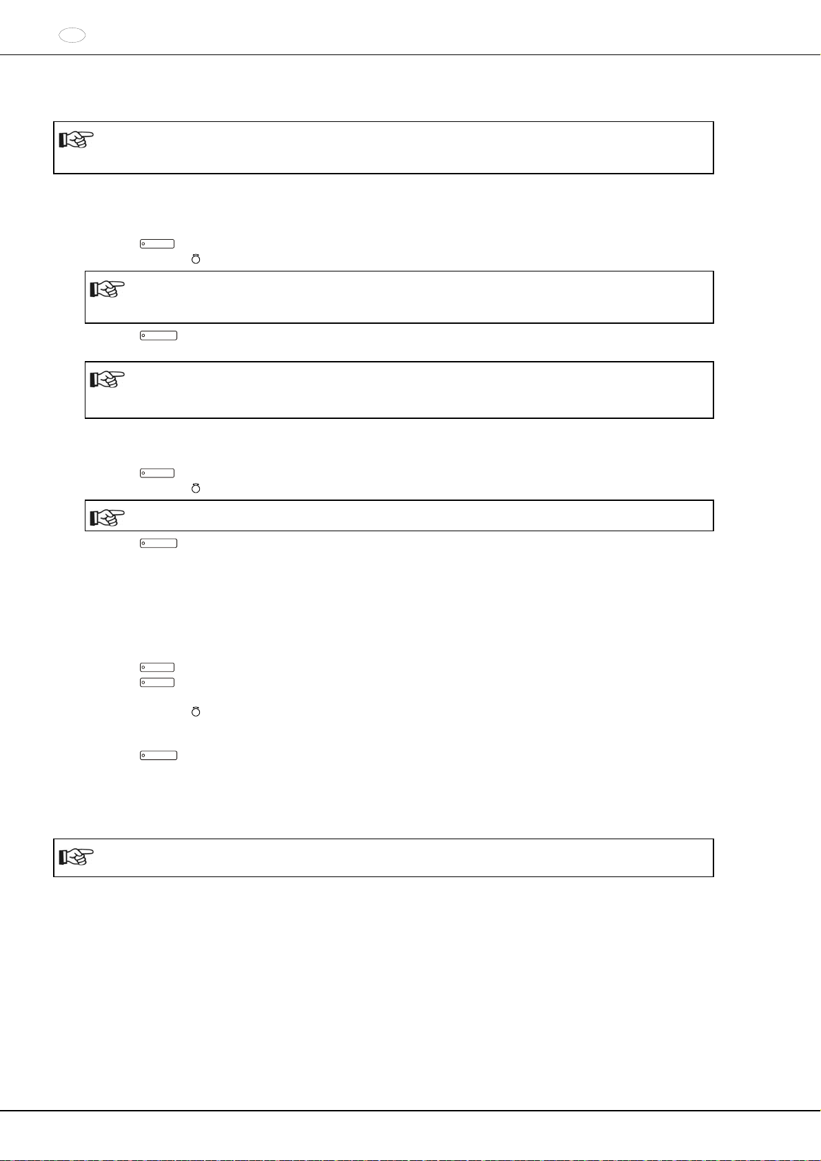
Die Taste
Mit dem Drehknopf
PROG
so oft drücken, bis der Parameter STO angezeigt wird.
den gewünschten Programmplatz einstellen.
Wird hinter dem Programmplatz ein "+" angezeigt, so sind die Daten schreibgeschützt. In diesem Fall
muss zuerst der Schreibschutz aufgehoben werden, bevor gespeichert werden kann (siehe Kapitel
"Schreibschutz für Programme").
Die Taste
START
drücken, um die Einstellungen auf dem gewünschten Programmplatz zu speichern. Als
Bestätigung wird kurzzeitig Program store .. angezeigt.
Die vorherigen Daten des Programmplatzes werden beim Speichern überschrieben.
Wird "Protected !!" angezeigt, sind die Daten auf dem Programmplatz schreibgeschützt und es wird
nicht gespeichert.
16.2 Programme abrufen
PROG
Die Taste
Mit dem Drehknopf
drücken. Der Parameter RCL wird angezeigt.
den gewünschten Programmplatz einstellen.
Wird hinter dem Programmplatz ein "+" angezeigt, so sind die Daten schreibgeschützt.
Die Taste
START
drücken. Als Bestätigung wird kurzzeitig Program recall .. angezeigt.
Die Zentrifugations-Daten des angewählten Programmplatzes werden angezeigt.
16.3 Schreibschutz für Programme
Die Programme können gegen unbeabsichtigtes Ändern geschützt werden.
Der Schreibschutz kann, bei Stillstand des Rotors, wie folgt aktiviert oder deaktiviert werden:
Das gewünschte Programm abrufen (siehe Kapitel "Programme abrufen").
Die Taste
Die Taste
PROG
drücken. Der Parameter RCL wird angezeigt.
PROG
8 Sekunden gedrückt halten.
Nach 8 Sekunden erscheint z. B. Set Protection = 1- in der Anzeige.
Mit dem Drehknopf "+" oder "-" einstellen.
+ = Programm ist schreibgeschützt,
- = Programm ist nicht schreibgeschützt.
START
Die Taste
drücken um die Einstellung zu speichern.
16.4 Programmverknüpfung
Mit Hilfe der Programmverknüpfung können mehrere Zentrifugationsläufe miteinander verknüpft werden.
Eine Programmverknüpfung ist nur möglich, wenn diese aktiviert ist (Parameter Multi programs = on; siehe
Kapitel "Programmverknüpfung aktivieren oder deaktivieren").
24/178
t
16.4.1 Programmverknüpfung aktivieren oder deaktivieren
Die Programmverknüpfung kann, bei Stillstand des Rotors, wie folgt aktiviert oder deaktiviert werden:
T/°C
Durch Drücken der Taste
Der Vorgang kann jederzeit durch Drücken der Taste
kann im Menü rückwärts geblättert werden.
OPEN / STOP
abgebrochen werden. In diesem Fall
werden die Einstellungen nicht gespeichert.
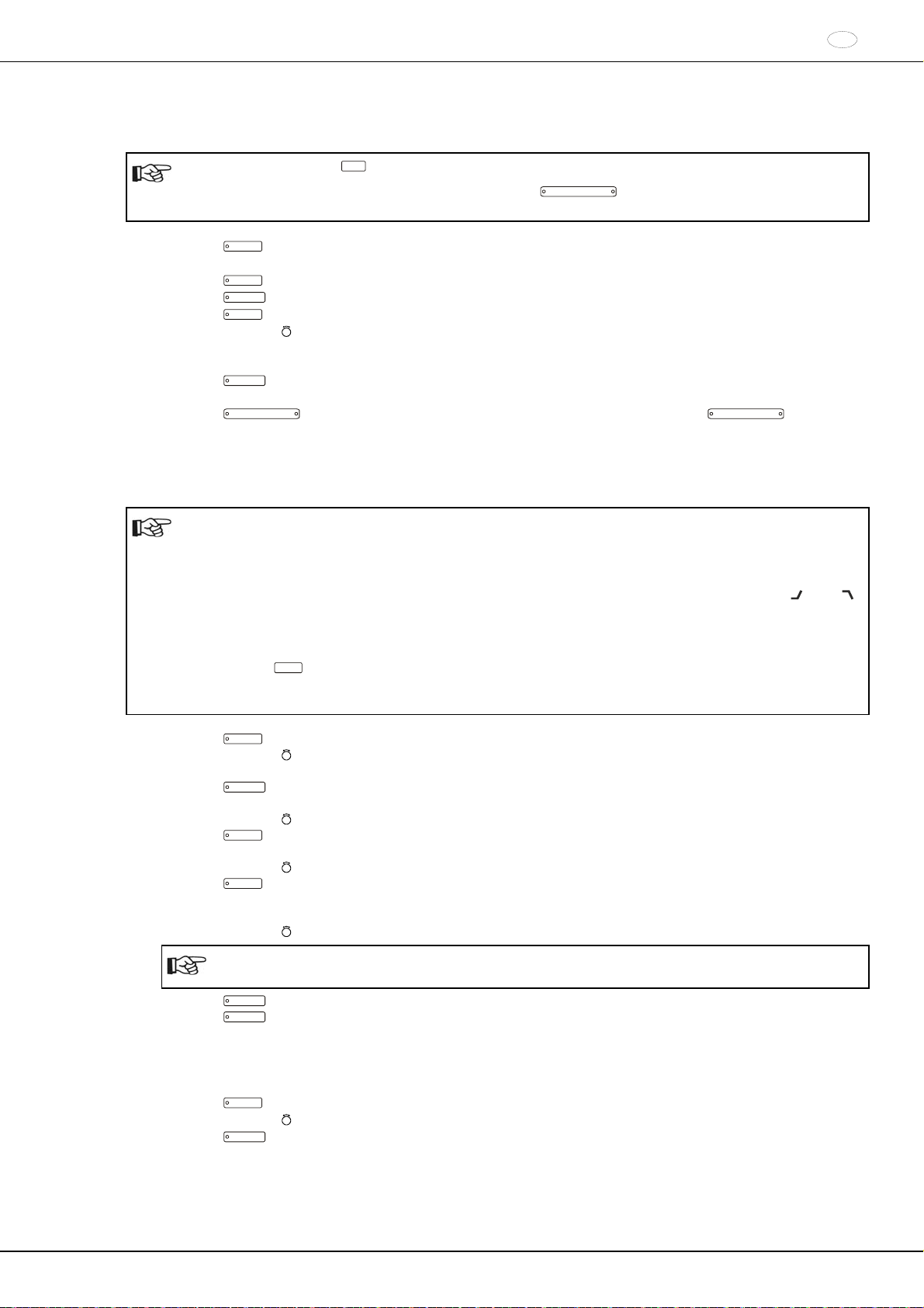
Die Taste
PROG
8 Sekunden gedrückt halten.
Nach 8 Sekunden erscheint Machine Menu in der Anzeige.
Die Taste
Die Taste
Die Taste
PROG
so oft drücken bis -> Settings angezeigt wird.
START
drücken. Es wird SOUND / BELL = off/on angezeigt.
PROG
so oft drücken bis Multi programs = off/on angezeigt wird.
Mit dem Drehknopf off oder on einstellen.
off = Programmverknüpfung deaktiviert,
on = Programmverknüpfung aktiviert.
Die Taste
START
drücken um die Einstellung zu speichern.
Als Bestätigung wird kurzzeitig Store Settings ... und anschließend -> Settings angezeigt.
Die Taste
OPEN / STOP
1x drücken, um das Menü "Settings" zu verlassen oder die Taste
OPEN / STOP
2x
drücken, um das "Machine Menu" zu verlassen.
16.4.2 Programme verknüpfen oder eine Programmverknüpfung ändern
Es können 25 Programmverknüpfungen gespeichert werden (Programmplätze A bis Z, Programmplatz J gibt
es nicht). Eine Programmverknüpfung kann maximal aus 20 Programmen bestehen.
In einer Programmverknüpfung erfolgt die Anpassung der Drehzahl von einem Programm zum nächsten
Programm immer mit dem Anlaufparameter des nächsten Programms.
Es dürfen keine Dauerlauf-Programme oder Programme mit An- und Auslaufzeiten (Parameter
verknüpft werden.
In einer Programmverknüpfung können keine Zentrifugations–Parameter geändert werden. Eine Änderung der
Parameter ist nur in den einzelnen Programmen möglich.
Mit der Taste
TIME
kann während des Zentrifugationslaufes die Gesamtlaufzeit der Programmverknüpfung
(z. B. =00:05:30) und die Laufzeit des gerade laufenden Programms (z. B. t B.02=00:0 1:00) abgerufen
werden.
1. Die Taste
PROG
so oft drücken bis der Parameter EDIT A…Z angezeigt wird.
2. Mit dem Drehknopf den gewünschten Programmplatz einstellen, auf dem die Programmverknüpfung gespeichert werden soll.
START
3. Die Taste
drücken. Es wird der Programmplatz der Programmverknüpfung und das erste Programm der
Programmverknüpfung angezeigt, z. B. EDIT B.01 = 01.
4. Mit dem Drehknopf
5. Die Taste
PROG
das erste Programm der Programmverknüpfung einstellen.
drücken. Das nächste Programm der Programmverknüpfung wird angezeigt, z. B. EDIT B.02 =
END.
6. Mit dem Drehknopf
7. Die Taste
PROG
das nächste Programm der Programmverknüpfung einstellen.
drücken. Das nächste Programm der Programmverknüpfung wird angezeigt, z. B. EDIT B.03 =
END.
8. Die Schritte 6 und 7 so oft wiederholen, bis alle Programme eingestellt sind.
9. Mit dem Drehknopf
END einstellen (Drehknopf entgegen dem Uhrzeigersinn drehen).
DE
und t)
Bei Programmverknüpfungen die aus 20 Programmen bestehen kann nach dem 20. Programm kein
END eingestellt werden.
10. Die Taste
11. Die Taste
START
drücken. Es wird z. B. STO B angezeigt.
START
drücken um die Programmverknüpfung zu speichern.
Als Bestätigung wird kurzzeitig Multi program store .. angezeigt.
16.4.3 Programmverknüpfung abrufen
PROG
Die Taste
Mit dem Drehknopf
Die Taste
so oft drücken bis der Parameter RCL A…Z angezeigt wird.
den gewünschten Programmplatz einstellen.
START
drücken. Als Bestätigung wird kurzzeitig Multi program recall .. angezeigt.
Die Zentrifugations-Daten des ersten Programms der Programmverknüpfung werden angezeigt.
25/178
DE
16.5 Automatischer Zwischenspeicher
Der Programmplatz 0 dient als Zwischenspeicher für die Zentrifugations-Daten des zuletzt erfolgten
Zentrifugationslaufes.
Auf diesem Programmplatz können keine Programme gespeichert werden.
Nach jedem Start eines Zentrifugationslaufes werden die zum Lauf verwendeten Zentrifugations-Daten automatisch
auf Programmplatz "0" gespeichert und können abgerufen werden.
17 Zentrifugation
Während eines Zentrifugationslaufes dürfen sich gemäß EN / IEC 61010-2-020, in einem Sicherheitsbereich
von 300 mm um die Zentrifuge herum, keine Personen, Gefahrstoffe und Gegenstände befinden.
Bei Zentrifugen mit Option Heizen / Kühlen muss nach einem Zentrifugationslauf mit sehr hoher Temperatur
(z.B. +90°C), so lange gewartet werden, bis der Deckel der Zentrifuge auf die Umgebungstemperatur
abgekühlt ist, bevor ein Zentrifugationslauf mit Kühlung durchgeführt werden darf. Wird dies nicht beachtet,
können Risse im Deckel entstehen.
Wird Enter max cycles = 30000 angezeigt, muss zuerst die, auf dem Gehänge angegebene, maximal
zulässige Anzahl der Laufzyklen eingegeben werden, bevor der Zentrifugationslauf erneut gestartet werden
kann (siehe Kapitel "Zyklenzähler").
Wird der zulässige Gewichtsunterschied innerhalb der Beladung des Rotors überschritten, wird der
Zentrifugationslauf während des Anlaufs abgebrochen und IMBALANCE angezeigt.
Ist die Drehzahl im angewählten Programm höher als die maximale Drehzahl des Rotors (Nmax), kann kein
Zentrifugationslauf gestartet werden. Es wird N > ROTOR MAX angezeigt (siehe Kapitel "Störungen").
Wird eine Anlaufzeit eingestellt, die länger als die Laufzeit ist, kann kein Zentrifugationslauf gestartet werden.
Es wird Acc time > Run time angezeigt (siehe Kapitel "Störungen").
Wird bei Programmverknüpfungen N > ROTOR MAX in Prog : z. B. 5, Runtime 00:00 in Prog : z. B. 5,
Empty Program oder Ramp Unit Time in Prog : z. B. 3 angezeigt, kann kein Zentrifugationslauf gestartet
werden (siehe Kapitel "Störungen").
Ein Zentrifugationslauf kann jederzeit durch Drücken der Taste
OPEN / STOP
abgebrochen werden.
Während eines Zentrifugationslaufes können Parameter angewählt und geändert werden (siehe Kapitel
"Einstellungen während des Zentrifugationslaufes ändern").
Mit den Tasten
RPM
und
RCF
kann jederzeit zwischen der RPM- und RCF-Anzeige umgeschaltet werden.
Eine Umschaltung ist nicht möglich, wenn mit Programmverknüpfungen gearbeitet wird. Wird mit der RCFAnzeige gearbeitet, ist die Eingabe des Zentrifugierradius notwendig.
Wird
OPEN OEFFNEN angezeigt, so ist eine weitere Bedienung der Zentrifuge erst nach einmaligem
Öffnen des Deckels möglich.
Wurde der Rotor gewechselt, findet kein Zentrifugationslauf statt, und es erscheint die Anzeige z. B.
Rotor 4 Nmax= 4500 R=184 mm (siehe Kapitel "Rotor-Erkennung").
Bedienfehler und Störungen werden angezeigt (siehe Kapitel "Störungen").
Den Netzschalter einschalten. Schalterstellung .
Den Rotor beladen und den Zentrifugendeckel schließen.
17.1 Zentrifugation mit Zeitvorwahl
Eine Laufzeit einstellen, ein Programm mit Zeitvorwahl oder eine Programmverknüpfung abrufen (siehe Kapitel
"Zentrifugations-Parameter eingeben", "Programme abrufen" oder "Programmverknüpfung").
Die Taste
START
drücken. Die LED in der Taste
START
blinkt bis der Rotor eingelesen ist, anschließend leuchtet
die LED.
Nach Ablauf der Zeit oder bei Abbruch des Zentrifugationslaufes durch Drücken der Taste
der Auslauf mit dem angewählten Auslauf-Parameter. Der Auslauf-Parameter wird angezeigt z. B.
rechte LED in der Taste
START
und OPEN OEFFNEN wird angezeigt. Die rechte LED in der Taste
linke LED in der Taste
OPEN / STOP
OPEN / STOP
leuchtet auf. Nach Stillstand des Rotors erlischt die LED in der Taste
OPEN / STOP
beginnt zu blinken und blinkt bis der Deckel geöffnet wird.
OPEN / STOP
erlischt ebenfalls, die
, erfolgt
9. Die
Während des Zentrifugationslaufes werden die Drehzahl des Rotors oder der daraus resultierende RCF-Wert, die
Proben-Temperatur (nur bei Zentrifuge mit Kühlung), und die verbleibende Zeit angezeigt.
26/178
DE
17.2 Dauerlauf
Die Minuten, Sekunden und Stunden auf "0" stellen oder ein Dauerlauf-Programm abrufen (siehe Kapitel
"Zentrifugations-Parameter eingeben" oder "Programme abrufen").
Die Taste
START
drücken. Die LED in der Taste
START
blinkt bis der Rotor eingelesen ist, anschließend leuchtet
die LED. Die Zeitzählung beginnt bei 00:00.
Die Taste
angewählten Auslauf-Parameter. Der Auslauf-Parameter wird angezeigt z. B.
OPEN / STOP
OEFFNEN wird angezeigt. Die rechte LED in der Taste
Taste
OPEN / STOP
drücken, um den Zentrifugationslauf zu beenden. Der Auslauf erfolgt mit dem
leuchtet auf. Nach Stillstand des Rotors erlischt die LED in der Taste
OPEN / STOP
OPEN / STOP
beginnt zu blinken und blinkt bis der Deckel geöffnet wird.
erlischt ebenfalls, die linke LED in der
9. Die rechte LED in der Taste
START
und OPEN
Während des Zentrifugationslaufes werden die Drehzahl des Rotors oder der daraus resultierende RCF-Wert, die
Proben-Temperatur (nur bei Zentrifuge mit Kühlung), und die gelaufene Zeit angezeigt.
17.3 Kurzzeitzentrifugation
Eine Kurzzeitzentrifugation ist nicht möglich, wenn mit Programmverknüpfungen gearbeitet wird.
Die Taste
START
gedrückt halten. Die LED in der Taste
START
blinkt bis der Rotor eingelesen ist, anschließend
leuchtet die LED. Die Zeitzählung beginnt bei 00:00.
Die Taste
angewählten Auslauf-Parameter. Der Auslauf-Parameter wird angezeigt z. B.
OPEN / STOP
OEFFNEN wird angezeigt. Die rechte LED in der Taste
Taste
START
wieder loslassen um den Zentrifugationslauf zu beenden. Der Auslauf erfolgt mit dem
leuchtet auf. Nach Stillstand des Rotors erlischt die LED in der Taste
OPEN / STOP
OPEN / STOP
beginnt zu blinken und blinkt bis der Deckel geöffnet wird.
erlischt ebenfalls, die linke LED in der
9. Die rechte LED in der Taste
START
und OPEN
Während des Zentrifugationslaufes werden die Drehzahl des Rotors oder der daraus resultierende RCF-Wert, die
Proben-Temperatur (nur bei Zentrifuge mit Kühlung), und die gelaufene Zeit angezeigt.
18 Einstellungen während des Zentrifugationslaufes ändern
Es ist nicht möglich Einstellungen während des Zentrifugationslaufes zu ändern, wenn mit Programmverknüpfungen gearbeitet wird.
Die Laufzeit, die Drehzahl, die Relative Zentrifugalbeschleunigung (RCF), die Anlauf- und Auslauf-Parameter sowie
die Temperatur (nur bei Zentrifuge mit Kühlung) können während des Zentrifugationslaufes verändert werden.
Den Wert des gewünschten Parameters verändern (siehe Kapitel "Zentrifugations-Parameter eingeben").
Die geänderte Einstellung wird auf Programmplatz "0" gespeichert (siehe Kapitel "Automatischer
Zwischenspeicher"). Das originale Programm wird nicht überschrieben. Die Programmplatz-Nummer wird in
Klammern () angezeigt. Dies bedeutet, dass die Zentrifugations-Daten in der Anzeige nicht mehr mit den
gespeicherten Zentrifugations-Daten des Programmplatzes übereinstimmen.
19 Integral RCF
2
Das Integral RCF ist ein Maß für die Sedimentationswirkung (∫ n
dt). Dieser Zahlenwert dient zum Vergleich von
Zentrifugationsläufen.
19.1 Integral RCF abfragen
Die Abfrage des Integral RCF ist nur möglich, wenn die Anzeige des Integral RCF aktiviert ist, siehe Kapitel
"Anzeige des Integral RCF aktivieren oder deaktivieren".
Das Integral RCF wird nicht gespeichert. Nach Start des nächsten Zentrifugationslaufes oder nach
Ausschalten des Gerätes wird das Integral RCF gelöscht.
Ist die Funktion "Timing begins at Speed" angewählt, beginnt die Berechnung des Integral RCF erst nach
Erreichen der eingestellten Drehzahl.
Die Taste
(=4.8667e+05 = 4,8667 10
Die Taste
Bei Bedarf die Taste
RCF
so oft drücken bis das Integral RCF angezeigt wird, z. B. =4.8667e+05
RCF
drücken. Es werden wieder die Zentrifugations-Daten angezeigt.
RPM
5
= 486670).
drücken, um auf die RPM-Anzeige umzuschalten.
27/178
DE
19.2 Anzeige des Integral RCF aktivieren oder deaktivieren
Die Anzeige des Integral RCF kann, bei Stillstand des Rotors, wie folgt aktiviert oder deaktiviert werden:
T/°C
Durch Drücken der Taste
Der Vorgang kann jederzeit durch Drücken der Taste
kann im Menü rückwärts geblättert werden.
OPEN / STOP
abgebrochen werden. In diesem Fall
werden die Einstellungen nicht gespeichert.
Die Taste
PROG
8 Sekunden gedrückt halten.
Nach 8 Sekunden erscheint Machine Menu in der Anzeige.
Die Taste
Die Taste
Die Taste
PROG
so oft drücken bis -> Settings angezeigt wird.
START
drücken. Es wird SOUND / BELL = off/on angezeigt.
PROG
so oft drücken bis RCF Integral = off/on angezeigt wird.
Mit dem Drehknopf off oder on einstellen.
off = Integral RCF deaktiviert,
on = Integral RCF aktiviert.
Die Taste
START
drücken um die Einstellung zu speichern.
Als Bestätigung wird kurzzeitig Store Settings ... und anschließend -> Settings angezeigt.
Die Taste
OPEN / STOP
1x drücken, um das Menü "Settings" zu verlassen oder die Taste
OPEN / STOP
2x
drücken, um das "Machine Menu" zu verlassen.
20 Not-Stop
Die Taste
Beim Not-Stop erfolgt der Auslauf mit Bremsstufe 9 (kürzeste Auslaufzeit). Die Bremsstufe
die Bremsstufe 0 vorgewählt, so erfolgt der Auslauf mit Bremsstufe
OPEN / STOP
2x drücken.
9 wird angezeigt. War
9d. Mit Bremsstufe 9d ist die Auslaufzeit
technisch bedingt länger als mit Bremsstufe 9.
21 Zyklenzähler
Die Verwendung des Zyklenzählers ist nur dann geeignet, wenn immer mit dem selben Gehängesatz
gearbeitet wird.
Die Zentrifuge ist mit einem Zyklenzähler ausgestattet, der die Laufzyklen (Zentrifugationsläufe) der verschiedenen
Rotorcodes zählt (siehe auch Kapitel "Rotorerkennung").
Bei Ausschwingrotoren wird der Zyklenzähler zum Erfassen der Laufzyklen (Zentrifugationsläufe) der Gehänge
verwendet.
Wenn ein Rotor zum ersten Mal von der Rotorerkennung erkannt wird, dann wird der Zentrifugationslauf
abgebrochen. Nach Drücken einer beliebigen Taste wird Enter max cycles = 30000 angezeigt. Die auf dem
Gehänge angegebene, maximal zulässige Anzahl der Laufzyklen muss eingegeben werden, bevor der
Zentrifugationslauf erneut gestartet werden kann (siehe Kapitel "Nach Start des ersten Zentrifugationslaufes die
maximal zulässige Anzahl der Laufzyklen eingeben oder den Zyklenzähler deaktivieren").
Bei Rotoren und Gehängen die nicht mit der maximal zulässigen Anzahl der Laufzyklen gekennzeichnet sind, muss
der Zyklenzähler deaktiviert werden (siehe Kapitel "Nach Start des ersten Zentrifugationslaufes die maximal
zulässige Anzahl der Laufzyklen eingeben oder den Zyklenzähler deaktivieren" und "Zyklenzähler deaktivieren oder
aktivieren").
Nach jedem Öffnen des Deckels wird kurzzeitig die Anzahl der Laufzyklen (Zentrifugationsläufe) des verwendeten
Rotorcodes angezeigt, z. B. CYCLES 5120 of 30000.
Ist die eingegebene maximal zulässige Anzahl der Laufzyklen eines Gehänges überschritten, wird nach jedem Start
eines Zentrifugationslaufes MAX CYCLES PASSED angezeigt, und der Zentrifugationslauf muss erneut gestartet
werden.
Wird MAX CYCLES PASSED angezeigt, müssen die Gehänge aus Sicherheitsgründen sofort gegen neue
Gehänge ausgetauscht werden.
Nach Austauschen der Gehänge muss der Zyklenzähler, bei Stillstand des Rotors, wieder auf "0" zurückgesetzt
werden (siehe Kapitel "Zyklenzähler auf "0" zurücksetzen und maximal zulässige Anzahl der Laufzyklen eingeben").
28/178
21.1 Nach Start des ersten Zentrifugationslaufes die maximal zulässige Anzahl der Laufzyklen eingeben
oder den Zyklenzähler deaktivieren
Es wird Enter max cycles = 30000 angezeigt.
Mit dem Drehknopf
die auf dem Gehänge angegebene maximal zulässige Anzahl der Laufzyklen einstellen.
Bei Rotoren und Gehängen die nicht mit der maximal zulässigen Anzahl der Laufzyklen gekennzeichnet sind,
muss der Zyklenzähler deaktiviert werden. Den Drehknopf
solange nach links drehen, bis disabled angezeigt
wird (disabled = Zyklenzähler deaktiviert).
START
Die Taste
drücken, um die Einstellung zu speichern.
Als Bestätigung wird kurzzeitig Store max cycles ... angezeigt.
21.2 Zyklenzähler auf "0" zurücksetzen und die maximal zulässige Anzahl der Laufzyklen eingeben
Dies kann, bei Stillstand des Rotors, wie folgt eingestellt werden:
T/°C
Durch Drücken der Taste
Der Vorgang kann jederzeit durch Drücken der Taste
kann im Menü rückwärts geblättert werden.
OPEN / STOP
abgebrochen werden. In diesem Fall
werden die Einstellungen nicht gespeichert.
Die Taste
PROG
8 Sekunden gedrückt halten.
Nach 8 Sekunden erscheint Machine Menu in der Anzeige.
Die Taste
Die Taste
Die Taste
Die Taste
PROG
so oft drücken bis -> Operating Time angezeigt wird.
START
drücken. Es werden die externen Betriebstunden angezeigt, z. B. OP Time ext = 0h25m.
PROG
so oft drücken bis die Laufzyklen angezeigt werden, z. B. Cycles = 30001 of 30000.
RCF
drücken. Die Anzahl der Laufzyklen wird in Klammern angezeigt, z. B. Cycles = 30001 of
30000.
Den Drehknopf nach links drehen, um die Anzahl der Laufzyklen auf "0" zurückzusetzen.
Die Taste
Werden die Laufzyklen nicht auf "0" zurückgesetzt, wird nach Drücken der Taste
actual cycles angezeigt und die Einstellung wird nicht gespeichert.
RCF
drücken. Die maximal zulässige Anzahl der Laufzyklen wird in Klammern angezeigt, z. B.
START
Max cycles =
Cycles = 0 of 30000.
Mit dem Drehknopf
Die Taste
START
die auf dem Gehänge angegebene maximal zulässige Anzahl der Laufzyklen einstellen.
drücken, um die Einstellungen zu speichern.
Als Bestätigung wird kurzzeitig Store cycles ... und anschließend die Laufzyklen angezeigt, z. B. Cycles = 0 of
30000.
Die Taste
OPEN / STOP
2x drücken, um das Menü "Operating Time" zu verlassen oder die Taste
OPEN / STOP
drücken, um das "Machine Menu" zu verlassen.
DE
3x
29/178
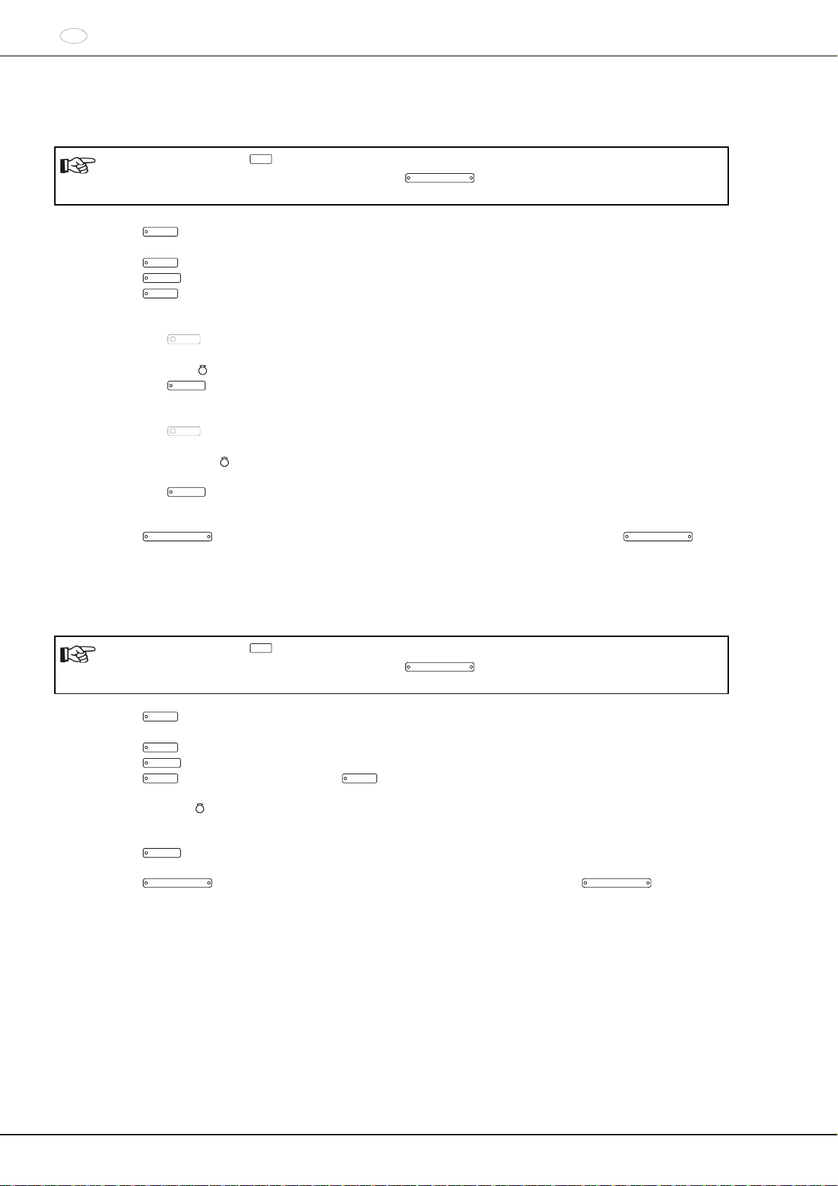
DE
21.3 Zyklenzähler deaktivieren oder aktivieren
Der Zyklenzähler kann, bei Stillstand des Rotors, wie folgt aktiviert oder deaktiviert werden:
T/°C
Durch Drücken der Taste
Der Vorgang kann jederzeit durch Drücken der Taste
kann im Menü rückwärts geblättert werden.
OPEN / STOP
abgebrochen werden. In diesem Fall
werden die Einstellungen nicht gespeichert.
PROG
Die Taste
8 Sekunden gedrückt halten.
Nach 8 Sekunden erscheint Machine Menu in der Anzeige.
Die Taste
Die Taste
Die Taste
PROG
so oft drücken bis -> Operating Time angezeigt wird.
START
drücken. Es werden die externen Betriebstunden angezeigt, z. B. OP Time ext = 0h25m.
PROG
so oft drücken bis bei aktiviertem Zyklenzähler die Laufzyklen angezeigt werden, z. B. Cycles =
5120 of 30000 und bei deaktiviertem Zyklenzähler Cycles = disabled angezeigt wird.
Zyklenzähler deaktivieren:
Die Taste
RCF
so oft drücken bis die maximal zulässige Anzahl der Laufzyklen in Klammern angezeigt
wird, z. B. Cycles = 5120 of 30000.
Den Drehknopf nach links drehen, um die maximal zulässige Anzahl der Laufzyklen auf "0" zu stellen.
START
Die Taste
drücken, um die Einstellung zu speichern.
Als Bestätigung wird kurzzeitig Store cycles ... und anschließend Cycles = disabled angezeigt.
Zyklenzähler aktivieren:
RCF
Die Taste
so oft drücken bis die maximal zulässige Anzahl der Laufzyklen in Klammern angezeigt
wird, z. B. Cycles = 0 of 0.
Mit dem Drehknopf
die auf dem Gehänge angegebene maximal zulässige Anzahl der Laufzyklen
einstellen.
Die Taste
START
drücken, um die Einstellung zu speichern.
Als Bestätigung wird kurzzeitig Store cycles ... und anschließend die Laufzyklen angezeigt, z. B. Cycles =
0 of 30000.
Die Taste
OPEN / STOP
2x drücken, um das Menü "Operating Time" zu verlassen oder die Taste
OPEN / STOP
drücken, um das "Machine Menu" zu verlassen.
22 Funktion "Dual time mode" aktivieren oder deaktivieren
Die Funktion "Dual time mode" kann, bei Stillstand des Rotors, wie folgt aktiviert oder deaktiviert werden:
T/°C
Durch Drücken der Taste
Der Vorgang kann jederzeit durch Drücken der Taste
kann im Menü rückwärts geblättert werden.
OPEN / STOP
abgebrochen werden. In diesem Fall
werden die Einstellungen nicht gespeichert.
Die Taste
PROG
8 Sekunden gedrückt halten.
Nach 8 Sekunden erscheint Machine Menu in der Anzeige.
Die Taste
Die Taste
Die Taste
PROG
so oft drücken bis -> Settings angezeigt wird.
START
drücken. Es wird SOUND / BELL = off/on angezeigt.
PROG
so oft drücken bis Die Taste
PROG
so oft drücken bis Dual time mode enabled/disabled
angezeigt wird.
Mit dem Drehknopf
enabled oder disabled einstellen.
disabled = Die Funktion ist deaktiviert,
enabled = Die Funktion ist aktiviert.
Die Taste
START
drücken um die Einstellung zu speichern.
Als Bestätigung wird kurzzeitig Store Settings ... und anschließend -> Settings angezeigt.
Die Taste
OPEN / STOP
1x drücken, um das Menü "Settings" zu verlassen oder die Taste
OPEN / STOP
drücken, um das "Machine Menu" zu verlassen.
3x
2x
30/178

G
G
G
23 An- und Auslaufzeiten aktivieren oder deaktivieren
Die An- und Auslaufzeiten können, bei Stillstand des Rotors, wie folgt aktiviert oder deaktiviert werden:
T/°C
Durch Drücken der Taste
Der Vorgang kann jederzeit durch Drücken der Taste
kann im Menü rückwärts geblättert werden.
OPEN / STOP
abgebrochen werden. In diesem Fall
werden die Einstellungen nicht gespeichert.
Die Taste
PROG
8 Sekunden gedrückt halten.
Nach 8 Sekunden erscheint Machine Menu in der Anzeige.
Die Taste
Die Taste
Die Taste
PROG
so oft drücken bis -> Settings angezeigt wird.
START
drücken. Es wird SOUND / BELL = off/on angezeigt.
PROG
so oft drücken bis Ramp Unit = Steps / Steps / Time angezeigt wird.
Mit dem Drehknopf Steps oder Steps / Time einstellen.
Steps = An- und Auslaufzeiten deaktiviert,
Steps / Time = An- und Auslaufzeiten aktiviert.
Die Taste
START
drücken um die Einstellung zu speichern.
Als Bestätigung wird kurzzeitig Store Settings ... und anschließend -> Settings angezeigt.
Die Taste
OPEN / STOP
1x drücken, um das Menü "Settings" zu verlassen oder die Taste
OPEN / STOP
drücken, um das "Machine Menu" zu verlassen.
24 Akustisches Signal
Das akustische Signal ertönt:
nach Auftreten einer Störung im 2 s-Intervall.
nach Beendigung des Zentrifugationslaufes und Stillstand des Rotors im 30 s-Intervall.
Durch Öffnen des Deckels oder Drücken einer beliebigen Taste wird das akustische Signal beendet.
Das akustische Signal kann, bei Stillstand des Rotors, folgendermaßen aktiviert oder deaktiviert werden:
T/°C
Durch Drücken der Taste
Der Vorgang kann jederzeit durch Drücken der Taste
kann im Menü rückwärts geblättert werden.
OPEN / STOP
abgebrochen werden. In diesem Fall
werden die Einstellungen nicht gespeichert.
Die Taste
PRO
8 Sekunden gedrückt halten.
Nach 8 Sekunden erscheint Machine Menu in der Anzeige.
Die Taste
Die Taste
PRO
so oft drücken bis -> Settings angezeigt wird.
START
drücken. Es wird SOUND / BELL = off/on angezeigt.
SOUND / BELL : Signal nach Beendigung des Zentrifugationslaufes.
Mit dem Drehknopf
Die Taste
PRO
off (aus) oder on (ein) einstellen.
drücken. Es wird SOUND / BELL error = off/on angezeigt.
SOUND / BELL error : Signal nach Auftreten einer Störung.
Mit dem Drehknopf
Die Taste
START
off (aus) oder on (ein) einstellen.
drücken um die Einstellung zu speichern.
Als Bestätigung wird kurzzeitig Store Settings ... und anschließend -> Settings angezeigt.
Die Taste
OPEN / STOP
1x drücken, um das Menü "Settings" zu verlassen oder die Taste
OPEN / STOP
drücken, um das "Machine Menu" zu verlassen.
2x
2x
DE
31/178

DE
25 Angezeigte Zentrifugations-Daten nach dem Einschalten
Nach dem Einschalten werden die Zentrifugations-Daten des Programms 1, oder die des zuletzt benutzten
Programms angezeigt.
Dies kann, bei Stillstand des Rotors, wie folgt eingestellt werden:
T/°C
Durch Drücken der Taste
Der Vorgang kann jederzeit durch Drücken der Taste
kann im Menü rückwärts geblättert werden.
OPEN / STOP
abgebrochen werden. In diesem Fall
werden die Einstellungen nicht gespeichert.
Die Taste
PROG
8 Sekunden gedrückt halten.
Nach 8 Sekunden erscheint Machine Menu in der Anzeige.
Die Taste
Die Taste
Die Taste
PROG
so oft drücken bis -> Settings angezeigt wird.
START
drücken. Es wird SOUND / BELL = off/on angezeigt.
PROG
so oft drücken bis Start program = Last/First angezeigt wird.
Mit dem Drehknopf Last oder First einstellen.
Last = zuletzt benutztes Programm, First = Programm 1.
Die Taste
START
drücken um die Einstellung zu speichern.
Als Bestätigung wird kurzzeitig Store Settings ... und anschließend -> Settings angezeigt.
Die Taste
OPEN / STOP
1x drücken, um das Menü "Settings" zu verlassen oder die Taste
OPEN / STOP
drücken, um das "Machine Menu" zu verlassen.
26 Temperatur-Einheit einstellen (nur bei Zentrifuge mit Kühlung)
Die Temperatur kann in Grad Celsius (°C) oder in Grad Fahrenheit (°F) eingegeben werden.
Dazu muss die Temperatur-Einheit, bei Stillstand des Rotors, wie folgt eingestellt werden:
T/°C
Durch Drücken der Taste
Der Vorgang kann jederzeit durch Drücken der Taste
kann im Menü rückwärts geblättert werden.
OPEN / STOP
abgebrochen werden. In diesem Fall
werden die Einstellungen nicht gespeichert.
Die Taste
PROG
8 Sekunden gedrückt halten.
Nach 8 Sekunden erscheint Machine Menu in der Anzeige.
Die Taste
Die Taste
Die Taste
Mit dem Drehknopf
Die Taste
PROG
so oft drücken bis -> Settings angezeigt wird.
START
drücken. Es wird SOUND / BELL = off/on angezeigt.
PROG
so oft drücken bis Temp Unit = Celsius/Fahrenheit angezeigt wird.
Celsius oder Fahrenheit einstellen.
START
drücken um die Einstellung zu speichern.
Als Bestätigung wird kurzzeitig Store Settings ... und anschließend -> Settings angezeigt.
Die Taste
OPEN / STOP
1x drücken, um das Menü "Settings" zu verlassen oder die Taste
OPEN / STOP
drücken, um das "Machine Menu" zu verlassen.
2x
2x
32/178

27 Programm-Verriegelung einstellen
Bei Stillstand des Rotors können folgende Programm-Verriegelungen eingestellt werden::
LOCK 1 LOCK 1 wird im Feld " " angezeigt.
Programme können nur abgerufen, jedoch nicht verändert werden.
LOCK 2 LOCK 2 wird im Feld " " angezeigt.
Es können keine Programme abgerufen und verändert werden.
Die Zentrifuge kann über die Schnittstelle gesteuert werden (nur bei Zentrifuge mit Schnittstelle).
LOCK 3
keine Status-Anzeige.
Keine Programm-Verriegelung. Programme können abgerufen und geändert werden.
Der Vorgang kann jederzeit durch Drücken der Taste
werden die Einstellungen nicht gespeichert.
OPEN / STOP
abgebrochen werden. In diesem Fall
Die Taste
PROG
8 Sekunden gedrückt halten.
Nach 8 Sekunden erscheint Machine Menu in der Anzeige.
Die Taste
Die Taste
PROG
so oft drücken bis -> Change LOCK angezeigt wird.
START
drücken. Es wird der Lock-Status angezeigt.
Ist keine PIN eingegeben, wird z. B. LOCK = 3 confirm by START angezeigt.
Ist eine PIN eingegeben, wird z. B. LOCK = 3 angezeigt.
Mit dem Drehknopf
den gewünschten Lock-Status einstellen.
DE
Ist eine PIN eingegeben, wird PIN = ---- confirm by START angezeigt. In diesem Fall muss zuerst mit
dem Drehknopf die gültige PIN eingestellt, und anschließend die Taste
START
gedrückt werden, bevor
der Lock-Status eingestellt werden kann.
Die Taste
START
drücken um die Einstellung zu speichern.
Als Bestätigung wird kurzzeitig z. B. Store LOCK 2 ... und anschließend -> Change LOCK angezeigt.
Die Taste
OPEN / STOP
1x drücken, um das Menü "Change LOCK" zu verlassen oder die Taste
OPEN / STOP
2x
drücken, um das "Machine Menu" zu verlassen.
28 PIN (Persönliche Identifikationsnummer)
Um das Ändern der Programm-Verriegelung durch unberechtigte Personen zu verhindern, kann eine PIN eingestellt
werden.
Ab Werk ist keine PIN eingestellt.
33/178

DE
28.1 PIN einstellen oder ändern
Die PIN kann, bei Stillstand des Rotors, wie folgt eingestellt werden:
Der Vorgang kann jederzeit durch Drücken der Taste
werden die Einstellungen nicht gespeichert.
OPEN / STOP
Die Taste
PROG
8 Sekunden gedrückt halten.
Nach 8 Sekunden erscheint Machine Menu in der Anzeige.
Die Taste
Die Taste
PROG
so oft drücken bis -> Change PIN angezeigt wird.
START
drücken. Es wird old PIN = ---- <START> angezeigt.
Mit dem Drehknopf die gültige PIN einstellen.
Wird die PIN zum ersten Mal eingestellt, dann diesen Schritt überspringen, oder "0000" einstellen.
Eingabehilfe:
Die jeweilige Taste gedrückt halten.
: nur die 1000er Stelle der PIN wird verändert.
RCF
: nur die 100er Stelle der PIN wird verändert.
RPM
: nur die 10er Stelle der PIN wird verändert.
START
Die Taste
Wurde eine falsche PIN eingestellt, wird wieder old PIN = ---- <START> angezeigt. In diesem Fall mit
dem Drehknopf die gültige PIN einstellen, und anschließend die Taste
drücken. Es wird new PIN = ---- <START> angezeigt.
abgebrochen werden. In diesem Fall
START
drücken.
Mit dem Drehknopf die neue PIN einstellen.
Zum Deaktivieren der PIN muss "0000" eingestellt werden.
Die Taste
START
drücken um die Einstellung zu speichern.
Als Bestätigung wird kurzzeitig Store PIN ... und anschließend -> Change PIN angezeigt.
Die Taste
OPEN / STOP
1x drücken, um das Menü "Change PIN" zu verlassen oder die Taste
OPEN / STOP
2x
drücken, um das "Machine Menu" zu verlassen.
28.2 Vorgehensweise bei verlorener PIN
Wurde die PIN verloren, kann eine sogenannte Help-Zahl abgerufen werden. Mit Hilfe dieser Zahl kann der Hersteller
eine PIN errechnen, welche die bisher gültige PIN ersetzt. Im Bedarfsfall wenden Sie sich bitte an Ihren Lieferanten.
Die Taste
PROG
8 Sekunden gedrückt halten.
Nach 8 Sekunden erscheint Machine Menu in der Anzeige.
Die Taste
Die Taste
Die Taste
PROG
so oft drücken bis -> Change PIN angezeigt wird.
START
drücken. Es wird old PIN = ---- <START> angezeigt.
PROG
drücken. Es wird Get HELP # no angezeigt.
Nach Abrufen der Help-Zahl wird die bisherige PIN ungültig.
Mit dem Drehknopf yes einstellen.
Die Taste
Mit dem Drehknopf
Die Taste
START
drücken. Es wird Are you sure ? no angezeigt.
yes einstellen.
START
drücken. Es wird die Help-Zahl angezeigt, z. B. HELP # = 5487.
Diese Help-Zahl notieren und damit die benötigte PIN anfordern.
Mit Hilfe der erhaltenen PIN eine neue PIN einstellen (siehe Kapitel "PIN einstellen oder ändern").
34/178

DE
29 Adresse der Zentrifuge
Die Adresse ist ab Werk auf ] = 29. Adresse eingestellt.
30 Die Betriebsstunden, die Zentrifugationsläufe und die Zyklenzähler abfragen
Die Betriebsstunden sind in interne und externe Betriebsstunden aufgeteilt.
Interne Betriebsstunden: Gesamte Zeit, die das Gerät eingeschaltet war.
Externe Betriebsstunden: Gesamte Zeit der bisherigen Zentrifugationsläufe.
Die Abfrage kann, bei Stillstand des Rotors, wie folgt durchgeführt werden:
T/°C
Durch Drücken der Taste
kann im Menü rückwärts geblättert werden.
Die Taste
PROG
8 Sekunden gedrückt halten.
Nach 8 Sekunden erscheint Machine Menu in der Anzeige.
Die Taste
Die Taste
Die Taste
Die Taste
Die Taste
PROG
so oft drücken bis -> Operating Time angezeigt wird.
START
drücken. Es werden die externen Betriebsstunden angezeigt, z. B. OP Time ext = 0h25m.
PROG
drücken. Es werden die internen Betriebsstunden angezeigt, z. B. OP Time int = 1h36m.
PROG
drücken. Die Anzahl aller Zentrifugationsläufe wird angezeigt, z. B. Number of Starts = 10.
PROG
drücken. Die Anzahl der Laufzyklen (Zentrifugationsläufe) des verwendeten Rotorcodes seit
dem letzten Zurücksetzen des Zyklenzählers auf "0" und die zulässige Anzahl der Laufzyklen werden angezeigt,
z. B. CYCLES = 5120 of 30000.
PROG
Die Taste
drücken. Die Anzahl aller Laufzyklen (Zentrifugationsläufe) des verwendeten Rotorcodes wird
angezeigt, z. B. Rotor cycles total = 37490. Dieser Wert ist nicht einstellbar.
Die Taste
OPEN / STOP
2x drücken, um das Menü "Operating Time" zu verlassen oder die Taste
OPEN / STOP
3x
drücken, um das "Machine Menu" zu verlassen.
31 System-Informationen abfragen
Folgende System-Informationen können abgefragt werden:
Zentrifugen-Modell,
Netzspannung,
Rotor-Informationen,
Programmversion der Zentrifuge,
Programmversion des Frequenzumrichters
Die System-Informationen können, bei Stillstand des Rotors, wie folgt abgefragt werden:
Durch Drücken der Taste
Die Taste
PROG
8 Sekunden gedrückt halten.
T/°C
kann im Menü rückwärts geblättert werden.
Nach 8 Sekunden erscheint Machine Menu in der Anzeige.
Die Taste
Die Taste
Die Taste
Die Taste
PROG
so oft drücken bis -> Info angezeigt wird.
START
drücken. Es wird das Zentrifugen-Modell angezeigt.
PROG
drücken. Es wird die Netzspannung angezeigt, z. B. Mains Voltage : 230 V.
PROG
drücken. Es werden der Rotorcode (Rotor), die maximale Drehzahl des Rotors (Nmax) und der
voreingestellte Zentrifugierradius (R) des zuletzt durch die Rotorerkennung erkannten Rotors angezeigt, z. B.
Rotor 4 : Nmax = 4500 R=184.
Der zuletzt erkannte Rotor ist mit einem Stern () gekennzeichnet. Mit dem Drehknopf können nun die
Informationen der in der Zentrifuge zugelassenen Rotoren angezeigt werden.
Die Taste
Die Taste
PROG
drücken. Es wird die Programmversion der Zentrifuge angezeigt, z. B. SW-Version = 01.00.
PROG
drücken. Es wird die Programmversion des Frequenzumrichters angezeigt, z. B. FC-SW-
Version = 4.
Die Taste
OPEN / STOP
2x drücken, um das Menü "Info" zu verlassen oder die Taste
OPEN / STOP
3x drücken, um
das "Machine Menu" zu verlassen.
32 Sofortige Anzeige der Zentrifugations-Daten nach dem Einschalten
Den Netzschalter einschalten. (Schalterstellung ).
Bei der ersten optischen Änderung in der Anzeige (inverse Anzeige) eine beliebige Taste drücken und gedrückt
halten. Die Zentrifugations-Daten werden sofort angezeigt.
35/178

DE
33 Kühlung (nur bei Zentrifuge mit Kühlung)
Die Temperatur kann von -20°C bis +40°C / -4°F bis +104°F eingestellt werden. Bei Zentrifugen mit Option
Heizen/Kühlen ist die Temperatur von -20°C bis +90°C / -4°F bis +194°F einstellbar. Die tiefste erreichbare
Temperatur ist rotorabhängig (siehe Kapitel "Anhang/Appendix, Rotoren und Zubehör/Rotors and accessories").
33.1 Standby-Kühlung
Bei Stillstand des Rotors und geschlossenem Deckel wird der Schleuderraum auf die vorgewählte Temperatur
gekühlt, wenn diese niedriger als 20°C / 68°F ist.
Während der Standby-Kühlung wird die vorgewählte Temperatur angezeigt.
33.2 Vorkühlen des Rotors
Zum schnellen Vorkühlen des unbeladenen Rotors und des Zubehörs, empfiehlt sich ein Zentrifugationslauf
mit den Einstellungen Dauerlauf und einer Drehzahl von ca. 20% der maximalen Drehzahl des Rotors.
Die Vorkühlung erfolgt automatisch mit Programm PREC (PRECOOLING).
Eine Vorkühlung ist nicht möglich, wenn mit Programmverknüpfungen gearbeitet wird.
Die Taste drücken. Die LED in der Taste blinkt bis der Rotor eingelesen ist, anschließend leuchtet die
LED.
Nach Ablauf der Zeit oder bei Abbruch des Zentrifugationslaufes durch Drücken der Taste
der Auslauf mit dem angewählten Auslauf-Parameter. Der Auslauf-Parameter wird angezeigt z. B.
rechte LED in der Taste
und OPEN OEFFNEN wird angezeigt. Die rechte LED in der Taste
LED in der Taste
OPEN / STOP
OPEN / STOP
leuchtet auf. Nach Stillstand des Rotors erlischt die LED in der Taste
OPEN / STOP
erlischt ebenfalls, die linke
beginnt zu blinken und blinkt bis der Deckel geöffnet wird.
OPEN / STOP
, erfolgt
9. Die
Während des Zentrifugationslaufes werden die Drehzahl des Rotors oder der daraus resultierende RCF-Wert, die
Proben-Temperatur, und die verbleibende oder die gelaufene Zeit angezeigt.
33.3 Zeitverzögerte Kühlung
Bei Bedarf kann eingestellt werden, dass nach Start des Zentrifugationslaufes die Kühlung zeitverzögert erfolgt.
Die Verzögerungszeit ist von 15 bis 900 Sekunden, in 1 Sekunden-Schritten einstellbar. Wird keine Zeitverzögerung
gewünscht, muss "0" eingestellt werden. Ab Werk ist keine Verzögerungszeit eingestellt.
Die Verzögerungszeit kann, bei Stillstand des Rotors, wie folgt eingestellt werden:
Die Taste
PROG
8 Sekunden gedrückt halten.
Nach 8 Sekunden erscheint Machine Menu in der Anzeige.
Die Taste
Die Taste
Die Taste
Mit dem Drehknopf
PROG
so oft drücken bis -> Settings angezeigt wird.
START
drücken. Es wird SOUND / BELL = off/on angezeigt.
PROG
so oft drücken bis die Verzögerungszeit angezeigt wird, z. B. Cool acc time = 0.
den gewünschten Wert einstellen.
0 = keine Verzögerungszeit
START
Die Taste
drücken um die Einstellung zu speichern.
Als Bestätigung wird kurzzeitig Store Settings ... und anschließend -> Settings angezeigt.
Die Taste
OPEN / STOP
1x drücken, um das Menü "Settings" zu verlassen oder die Taste
OPEN / STOP
2x
drücken, um das "Machine Menu" zu verlassen.
33.4 Einschalten der Kühlung während des Auslaufs verhindern
Bei Bedarf kann eingestellt werden, dass am Ende des Zentrifugationslaufes während des Auslaufs, nach Erreichen
einer eingestellten Drehzahl, die Kühlung nicht mehr einschaltet.
Dadurch kann ein eventuelles Aufwirbeln des Sediments in der Probe verhindert werden.
Diese Drehzahl ist von 0 RPM bis zur maximalen Drehzahl des Rotors (Nmax) in 10er Schritten einstellbar.
Die Drehzahl kann, bei Stillstand des Rotors, wie folgt eingestellt werden:
Die Taste
PROG
8 Sekunden gedrückt halten.
Nach 8 Sekunden erscheint Machine Menu in der Anzeige.
Die Taste
Die Taste
Die Taste
Mit dem Drehknopf
Die Taste
PROG
so oft drücken bis -> Settings angezeigt wird.
START
drücken. Es wird SOUND / BELL = off/on angezeigt.
PROG
so oft drücken bis Cool dec speed = … rpm angezeigt wird.
den gewünschten Wert einstellen.
START
drücken um die Einstellung zu speichern.
Als Bestätigung wird kurzzeitig Store Settings ... und anschließend -> Settings angezeigt.
Die Taste
OPEN / STOP
1x drücken, um das Menü "Settings" zu verlassen oder die Taste
OPEN / STOP
2x
drücken, um das "Machine Menu" zu verlassen.
36/178

34 Heizung (nur bei Zentrifuge mit Option Heizen/Kühlen)
Während des Zentrifugationslaufes wird bei Bedarf der Schleuderraum auf die vorgewählte Temperatur geheizt. Bei
Stillstand des Rotors ist die Heizung ausgeschaltet.
Verbrennungsgefahr! Die Oberflächen-Temperatur des Heizelements im Schleuderraum der Zentrifuge kann
bis zu 500°C / 932°F betragen. Das Heizelement nicht berühren.
Kunststoff-Nutgehänge dürfen nur bei Temperaturen bis maximal 40°C / 104°F verwendet werden.
Die Heizung kann bei Bedarf auch deaktiviert werden.
Die Heizung kann, bei Stillstand des Rotors, wie folgt aktiviert oder deaktiviert werden:
Die Taste
Mit dem Drehknopf
off = Heizung deaktiviert,
on = Heizung aktiviert.
Die Taste
Es werden die Zentrifugations-Daten angezeigt.
35 Relative Zentrifugalbeschleunigung (RCF)
Die relative Zentrifugalbeschleunigung (RCF) wird als Vielfaches der Erdbeschleunigung (g) angegeben. Sie ist ein
einheitsfreier Zahlenwert und dient zum Vergleich der Trenn- und Sedimentationsleistung.
Die Berechnung erfolgt nach der Formel:
T/°C
so oft drücken, bis Heater = on/off angezeigt wird.
off oder on einstellen.
T/°C
oder
START
RCF
drücken, um die Einstellung zu speichern.
2
RPM
1000
1,118r
1000
RPM
RCF
1,118r
DE
RCF = Relative Zentrifugalbeschleunigung
RPM = Drehzahl
r = Zentrifugierradius in mm = Abstand von der Mitte der Drehachse bis zum Zentrifugiergefäßboden.
Zentrifugierradius siehe Kapitel "Anhang/Appendix, Rotoren und Zubehör/
Rotors and accessories".
Die relative Zentrifugalbeschleunigung (RCF) ist von der Drehzahl und dem Zentrifugierradius abhängig.
36 Zentrifugation von Stoffen oder Stoffgemischen mit einer höheren Dichte als 1,2 kg/dm3
Bei der Zentrifugation mit maximaler Drehzahl darf die Dichte der Stoffe oder Stoffgemische 1,2 kg/dm
überschreiten.
Bei Stoffen oder Stoffgemischen mit einer höheren Dichte muss die Drehzahl reduziert werden.
Die erlaubte Drehzahl lässt sich nach folgender Formel berechnen:
)(n Drehzahl Reduzierte
z.B.: Maximale Drehzahl 4000 RPM, Dichte 1,6 kg/dm
kg/dm³ 1,2
n
kg/dm³ 1,6
Wird im Ausnahmefall die, auf dem Gehänge angegebene, maximale Beladung überschritten, muss die Drehzahl
ebenfalls reduziert werden.
Die erlaubte Drehzahl lässt sich nach folgender Formel berechnen:
red
)(n Drehzahl Reduzierte
1,2
[kg/dm³] Dichte höhere
RPM 3464 RPM 4000
red
3
[g] Beladung maximale
red
[g] Beladung hetatsächlic
[RPM] Drehzahl maximale
[RPM] Drehzahl maximale
3
nicht
z.B.: Maximale Drehzahl 4000 RPM, maximale Beladung 300 g, tatsächliche Beladung 350 g
g 300
n
Bei eventuellen Unklarheiten ist Auskunft beim Hersteller einzuholen.
37/178
red
g 350
RPM 3703 RPM 4000

DE
37 Rotorerkennung
Nach Start eines jeden Zentrifugationslaufes wird eine Rotorerkennung durchgeführt.
Wurde der Rotor gewechselt, wird der Zentrifugationslauf nach der Rotorerkennung abgebrochen. Der Rotorcode
(Rotor), die maximale Drehzahl des Rotors (Nmax) und der voreingestellte Zentrifugierradius (R) des verwendeten
Rotors werden angezeigt, z. B. Rotor 4 Nmax= 4500 R=184 mm.
Wenn die maximale Drehzahl des verwendeten Rotors kleiner als die eingestellte Drehzahl ist, wird die
Drehzahl auf die maximale Drehzahl des Rotors begrenzt. In diesem Fall wird die Programmplatz-Nummer in
Klammern () angezeigt.
Die Taste
OPEN / STOP
drücken um den Deckel zu öffnen, oder die Taste
Zentrifugationslauf zu starten. Bei Zentrifugen mit Kühlung kann auch durch Drücken der Taste
START
drücken um den
die
Vorkühlung des Rotors gestartet werden.
Wenn der Zyklenzähler aktiviert ist, wird nach dem Öffnen des Deckels kurzzeitig die Anzahl der
Laufzyklen (Zentrifugationsläufe) des verwendeten Rotorcodes angezeigt, z. B. ROTORCYCLES 5120
of 30000 (siehe Kapitel "Zyklenzähler").
38 Notentriegelung
Bei einem Stromausfall kann der Deckel nicht motorisch entriegelt werden. Es muss eine Notentriegelung von Hand
durchgeführt werden.
Zur Notentriegelung die Zentrifuge vom Netz trennen.
Den Deckel nur bei Stillstand des Rotors öffnen.
Siehe Abbildung auf Seite 2.
Den Netzschalter ausschalten (Schalterstellung "0").
Durch das Fenster im Deckel schauen, um sich zu vergewissern, dass der Rotor stillsteht.
Den Sechskant-Stiftschlüssel waagerecht in die Bohrung (Fig. 1, A) einführen und vorsichtig eine halbe
Umdrehung im Uhrzeigersinn drehen, bis sich der Deckel öffnen lässt.
Den Sechskant-Stiftschlüssel wieder aus der Bohrung herausziehen.
Wenn nach dem Wiedereinschalten der Zentrifuge die linke LED in der Taste
OPEN / STOP
drücken, dass die motorische Deckelverriegelung wieder die Grundstellung (geöffnet) einnimmt.
OPEN / STOP
blinkt, die Taste
39 Pflege und Wartung
Das Gerät kann kontaminiert sein.
Vor der Reinigung den Netzstecker ziehen.
Bevor ein anderes als das vom Hersteller empfohlene Reinigungs- oder Dekontaminationsverfahren
angewandt wird, hat sich der Benutzer beim Hersteller zu vergewissern, dass das vorgesehene Verfahren
das Gerät nicht schädigt.
Zentrifugen, Rotoren und das Zubehör dürfen nicht in Spülmaschinen gereinigt werden.
Es darf nur eine Handreinigung und eine Flüssig-Desinfektion durchgeführt werden.
Die Wassertemperatur muss 20 – 25°C betragen.
Es dürfen nur Reinigungs- oder Desinfektionsmittel verwendet werden, die:
im pH-Bereich 5 - 8 liegen,
keine Ätzalkalien, Peroxide, Chlorverbindungen, Säuren und Laugen enthalten.
Um Korrosionserscheinungen durch Reinigungs- oder Desinfektionsmittel zu vermeiden sind die speziellen
Anwendungshinweise vom Hersteller des Reinigungs- oder Desinfektionsmittels unbedingt zu beachten.
38/178

39.1 Zentrifuge (Gehäuse, Deckel und Schleuderraum)
39.1.1 Oberflächenreinigung und -pflege
Das Gehäuse der Zentrifuge und den Schleuderraum regelmäßig säubern und bei Bedarf mit Seife oder einem
milden Reinigungsmittel und einem feuchten Tuch reinigen. Dies dient zum einen der Hygiene und es verhindert
Korrosion durch anhaftende Verunreinigungen.
Inhaltsstoffe geeigneter Reinigungsmittel:
Seife, anionische Tenside, nichtionische Tenside.
Nach dem Einsatz von Reinigungsmitteln, die Reste des Reinigungsmittels, durch Nachwischen mit einem
feuchten Tuch, entfernen.
Die Flächen müssen unmittelbar nach der Reinigung getrocknet werden.
Bei Bildung von Kondenswasser den Schleuderraum, durch Auswischen mit einem saugfähigen Tuch, trocknen.
Die Gummidichtung des Schleuderraums nach jeder Reinigung mit Talkum-Puder oder einem Gummi-
Pflegemittel leicht einreiben.
Der Schleuderraum ist jährlich auf Schäden zu überprüfen.
Werden sicherheitsrelevante Schäden festgestellt, darf die Zentrifuge nicht mehr in Betrieb genommen
werden. In diesem Fall ist der Kundendienst zu benachrichtigen.
39.1.2 Oberflächendesinfektion
Gelangt infektiöses Material in den Schleuderraum, so ist dieser umgehend zu desinfizieren.
Inhaltsstoffe geeigneter Desinfektionsmittel:
Äthanol, n-Propanol, Isopropanol, Glutardialdehyd, quaternäre Ammoniumverbindungen.
Nach dem Einsatz von Desinfektionsmitteln, die Reste des Desinfektionsmittels, durch Nachwischen mit einem
feuchten Tuch, entfernen.
Die Flächen müssen unmittelbar nach der Desinfektion getrocknet werden.
39.1.3 Entfernen radioaktiver Verunreinigungen
Das Mittel muss speziell für das Entfernen radioaktiver Verunreinigungen ausgewiesen sein.
Inhaltsstoffe geeigneter Mittel für das Entfernen radioaktiver Verunreinigungen:
Anionische Tenside, nichtionische Tenside, polyhydrierter Äthanol.
Nach dem Entfernen der radioaktiven Verunreinigungen, die Reste des Mittels, durch Nachwischen mit einem
feuchten Tuch, entfernen.
Die Flächen müssen unmittelbar nach dem Entfernen der radioaktiven Verunreinigungen getrocknet werden.
DE
39/178

DE
39.2 Rotoren und Zubehör
39.2.1 Reinigung und Pflege
Um einer Korrosion und Materialveränderungen vorzubeugen müssen die Rotoren und das Zubehör regelmäßig
mit Seife oder einem milden Reinigungsmittel und einem feuchten Tuch gereinigt werden. Die Reinigung wird
mindestens einmal wöchentlich empfohlen. Verschmutzungen müssen sofort entfernt werden.
Inhaltsstoffe geeigneter Reinigungsmittel:
Seife, anionische Tenside, nichtionische Tenside.
Nach dem Einsatz von Reinigungsmitteln, die Reste des Reinigungsmittels, durch Nachspülen mit Wasser (nur
außerhalb der Zentrifuge) oder Nachwischen mit einem feuchten Tuch, entfernen.
Die Rotoren und das Zubehör müssen unmittelbar nach der Reinigung getrocknet werden.
Winkelrotoren, Behälter und Gehänge aus Aluminium sind nach dem Trocknen mit säurefreiem Fett z.B.
Vaseline leicht einzufetten.
Bei Bio-Sicherheitssystemen (lieferbare Bio-Sicherheitssysteme siehe Kapitel "Anhang/Appendix, Rotoren und
Zubehör/Rotors and accessories") sind die Dichtungsringe regelmäßig (wöchentlich) zu prüfen und zu reinigen.
Bei Anzeichen von Rissbildung, Versprödung oder Abnutzung ist der Dichtungsring sofort auszutauschen. Die
Dichtungsringe nach jeder Reinigung mit Talkum-Puder oder einem Gummi-Pflegemittel leicht einreiben.
Um Korrosion infolge Feuchtigkeit zwischen Rotor und Motorwelle zu verhindern, sollte der Rotor mindestens
einmal im Monat ausgebaut, gereinigt und die Motorwelle leicht gefettet werden.
Die Rotoren und das Zubehör sind wöchentlich auf Verschleiß und Korrosionsschäden zu überprüfen.
Bei Ausschwingrotoren muss vor allem der Bereich der Tragzapfen und bei Gehängen die Nuten und der Boden
auf Risse geprüft werden.
Beispiel: Riss im Bereich der Nut:
Rotoren und Zubehör dürfen bei Anzeichen von Verschleiß oder Korrosion nicht mehr verwendet werden.
Den Rotor wöchentlich auf festen Sitz prüfen.
39.2.2 Desinfektion
Gelangt infektiöses Material auf die Rotoren oder auf das Zubehör, so muss eine geeignete Desinfektion
durchgeführt werden.
Inhaltsstoffe geeigneter Desinfektionsmittel:
Glutaraldehyd, Propanol, Ethylhexanol, anionische Tenside, Korrosionsinhibitoren.
Nach dem Einsatz von Desinfektionsmitteln, die Reste des Desinfektionsmittels, durch Nachspülen mit Wasser
(nur außerhalb der Zentrifuge) oder Nachwischen mit einem feuchten Tuch, entfernen.
Die Rotoren und das Zubehör müssen unmittelbar nach der Desinfektion getrocknet werden.
39.2.3 Entfernen radioaktiver Verunreinigungen
Das Mittel muss speziell für das Entfernen radioaktiver Verunreinigungen ausgewiesen sein.
Inhaltsstoffe geeigneter Mittel für das Entfernen radioaktiver Verunreinigungen:
Anionische Tenside, nichtionische Tenside, polyhydrierter Äthanol.
Nach dem Entfernen der radioaktiven Verunreinigungen, die Reste des Mittels, durch Nachspülen mit Wasser
(nur außerhalb der Zentrifuge) oder Nachwischen mit einem feuchten Tuch, entfernen.
Die Rotoren und das Zubehör müssen unmittelbar nach dem Entfernen der radioaktiven Verunreinigungen
getrocknet werden.
40/178

39.2.4 Tragzapfen
Bei Ausschwingrotoren müssen die Tragzapfen regelmäßig gefettet werden (Hettich-Schmierfett Nr. 4051), um ein
gleichmäßiges Ausschwingen der Gehänge zu gewährleisten.
39.2.5 Rotoren und Zubehör mit begrenzter Verwendungsdauer
Die Verwendung von bestimmten Rotoren, Gehängen und Zubehörteilen ist zeitlich begrenzt.
Diese sind mit der maximal erlaubten Anzahl der Laufzyklen oder dem Ablaufdatum und der maximalen Anzahl der
Laufzyklen oder nur mit dem Ablaufdatum gekennzeichnet, z.B.:
- "einsetzbar bis Ende: V. Quartal 2011 / usable until end of: V. Quartal 2011" oder
"einsetzbar bis Ende Monat/Jahr: 10/2011 / usable until end of month/year: 10/2011"
- "max. Laufzyklen / max. cycles: 40000"
Aus Sicherheitsgründen dürfen die Rotoren, Gehänge und Zubehörteile nicht mehr verwendet werden,
wenn entweder die darauf gekennzeichnete maximal erlaubte Anzahl der Laufzyklen oder das darauf
gekennzeichnete Ablaufdatum erreicht ist.
Die Anzahl der Zentrifugationsläufe kann abgefragt werden, siehe Kapitel "Abfrage der Betriebsstunden und der
Anzahl der Zentrifugationsläufe".
39.3 Autoklavieren
Das folgende Zubehör darf bei 121°C / 250°F (20 min) autoklaviert werden:
Ausschwingrotoren
Winkelrotoren aus Aluminium
Gehänge aus Metall
Deckel mit Bioabdichtung
Gestelle
Reduzierungen
Im Zweifelsfall muss beim Hersteller nachgefragt werden.
Über den Sterilitätsgrad kann keine Aussage gemacht werden.
DE
Die Deckel der Rotoren und Behälter müssen vor dem Autoklavieren abgenommen werden.
Das Autoklavieren beschleunigt den Alterungsprozess von Kunststoffen. Außerdem kann es bei
Kunststoffen Farbveränderungen verursachen.
Wir empfehlen nach dem Autoklavieren die Dichtungsringe von Bio-Sicherheitssystemen auszutauschen.
39.4 Zentrifugiergefäße
Bei Undichtigkeit oder nach dem Bruch von Zentrifugiergefäßen, sind zerbrochene Gefäßteile, Glassplitter und
ausgelaufenes Zentrifugiergut vollständig zu entfernen.
Die Gummieinlagen sowie die Kunststoff-Hülsen der Rotoren sind nach einem Glasbruch zu ersetzen.
Verbleibende Glassplitter verursachen weiteren Glasbruch !
Handelt es sich um infektiöses Material so ist umgehend eine Desinfektion durchzuführen.
41/178

DE
40 Störungen
Lässt sich der Fehler laut Störungstabelle nicht beheben, so ist der Kundendienst zu benachrichtigen.
Bitte den Zentrifugentyp und die Seriennummer angeben. Beide Nummern sind auf dem Typenschild der Zentrifuge
ersichtlich.
Einen NETZ-RESET durchführen:
Den Netzschalter ausschalten (Schalterstellung "0").
Mindestens 10 Sekunden lang warten und anschließend den Netzschalter wieder einschalten
(Schalterstellung "").
Anzeige Ursache Beseitigung
keine Anzeige --- keine Spannung.
Auslösen der Überstromschutzsicherung.
Auslösen des Sicherungsautomaten (nur
bei Typen 4701-01 und 4706-01).
Versorgungsspannung überprüfen.
Sicherungsautomat wieder
einschalten, siehe Kapitel
"Sicherungsautomat einschalten"
(nur bei Typen 4701-01 und 4706-
01).
Netzschalter EIN.
TACHO - ERROR 1, 2, 96 Tacho defekt.
Motor, Elektronik defekt.
Deckel öffnen.
Den Netzschalter ausschalten
(Schalterstellung "0").
Mindestens 10 Sekunden lang
warten.
Den Rotor von Hand kräftig drehen.
Den Netzschalter wieder
einschalten (Schalterstellung "").
Während des Einschaltens muss
sich der Rotor drehen.
IMBALANCE --- Der Rotor ist ungleichmäßig beladen.
Deckel öffnen.
Die Beladung des Rotors über-
prüfen, siehe Kapitel "Beladen des
Rotors".
Den Zentrifugationslauf wieder-
holen.
CONTROL - ERROR 4.1 – 4.5,6 Fehler Deckelverriegelung
N > MAX 5.0, 5.1 Überdrehzahl
N < MIN 13 Unterdrehzahl
ROTORCODE 10.1–10.3 Fehler Rotorcodierung
MAINS INTERRUPT --- Netzunterbrechung während des Zentrifu-
gationslaufes. (Der Zentrifugationslauf
wurde nicht beendet.)
VERSION-ERROR 12 Keine Übereinstimmung der Elektronik-
Komponenten
Fehler / Defekt Elektronik
CONTROL-ERROR 22,
Fehler / Defekt Elektronik
25.1–25.4
SER I/O - ERROR 31, 34,
Fehler / Defekt Elektronik
36
° C * - ERROR 51,
Fehler / Defekt Elektronik
53 – 55,
97, 98
° C * - ERROR 52.0,
52.1
FU / CCI - ERROR 60, 61.2-
Übertemperatur im Schleuderraum.
Fehler / Defekt Elektronik
Fehler / Defekt Elektronik / Motor
61.20,
61.128 -
61.131,
62
FU / CCI - ERROR 61.1 Netzspannung zu niedrig.
Fehler / Defekt Elektronik / Motor
Einen NETZ-RESET durchführen.
Deckel öffnen.
START
Taste
drücken.
Bei Bedarf den Zentrifugationslauf
wiederholen.
Einen NETZ-RESET durchführen.
Netzspannung überprüfen.
Einen NETZ-RESET durchführen.
42/178

Anzeige Ursache Beseitigung
SENSOR-ERROR 90 Fehler / Defekt Elektronik
SENSOR-ERROR 91 - 93 Fehler / Defekt Unwuchtsensor
NO ROTOR OR
ROTORCODE
--- Kein Rotor eingebaut.
Tacho defekt.
ERROR
N > ROTOR MAX ---
Drehzahl im angewählten Programm
größer als die maximale Drehzahl des
Rotors.
Der Rotor wurde gewechselt. Der eingebaute Rotor hat eine höhere maximale
Drehzahl als der vorher verwendete Rotor,
und er wurde noch nicht von der Rotorerkennung erkannt.
N > ROTOR MAX
in Prog : z. B. 3
Auf dem angezeigten Programmplatz
--befindet sich ein Programm, dessen
Drehzahl größer als die maximale
Drehzahl des Rotors ist.
Der Rotor wurde gewechselt. Der eingebaute Rotor hat eine höhere maximale
Drehzahl als der vorher verwendete Rotor,
und er wurde noch nicht von der Rotorerkennung erkannt.
Runtime 00:00
in Prog : z. B. 3
--- Auf dem angezeigten Programmplatz
befindet sich ein Dauerlauf-Programm.
Empty Program --- Auf dem angezeigten Programmplatz ist
keine Programmverknüpfung gespeichert.
Ramp Unit Time in
Prog : z. B. 3
--- Auf dem angezeigten Programmplatz
befindet sich ein Programm mit Anlaufund /oder Auslaufzeit.
Acc time > Run time --- Die eingestellte Anlaufzeit ist länger als
die Laufzeit.
FC INIT ERROR --- Fehler / Defekt Elektronik
FC VERSION
Fehler / Defekt Elektronik
ERROR
FATAL EEPROM
1 - 5 Fehler / Defekt Elektronik
ERROR
DE
Einen NETZ-RESET durchführen.
Deckel öffnen.
Rotor einbauen.
Drehzahl überprüfen und
korrigieren.
Eine Drehzahl, bis zur maximalen
Drehzahl des vorher verwendeten
Rotors, einstellen. Die Taste
START
drücken, um eine Rotorerkennung
durchzuführen, siehe Kapitel
"Rotorerkennung".
Drehzahl überprüfen und
korrigieren.
Eine Drehzahl, bis zur maximalen
Drehzahl des vorher verwendeten
Rotors, einstellen. Die Taste
START
drücken, um eine Rotorerkennung
durchzuführen, siehe Kapitel
"Rotorerkennung".
In der Programmverknüpfung das
Dauerlauf-Programm durch ein
Programm mit Zeitvorwahl ersetzen.
Eine Programmverknüpfung
abrufen.
In der Programmverknüpfung das
Programm durch ein Programm mit
Anlauf- und Bremsstufe ersetzen.
Eine Anlaufzeit einstellen, die kürzer
als die Laufzeit ist.
Einen NETZ-RESET durchführen.
43/178

DE
41 Sicherungsautomat einschalten
(nur bei Typen 4701-01 und 4706-01)
Den Netzschalter ausschalten und die Zentrifuge vom Netz trennen!
A
Der Sicherungsautomat befindet sich in der Frontblende unten rechts.
Den Kunststoffstift (A) des Sicherungsautomaten nach oben drücken.
Die Zentrifuge wieder ans Netz anschließen.
42 Rücksendung von Geräten
Vor der Rücksendung des Gerätes muss die Transportsicherung eingebaut werden.
Wird das Gerät oder dessen Zubehör an die Firma Andreas Hettich GmbH & Co. KG zurückgesandt, so muss dieses,
zum Schutz von Personen, Umwelt und Material, vor dem Versand dekontaminiert und gereinigt werden.
Eine Annahme von kontaminierten Geräten oder Zubehör behalten wir uns vor.
Anfallende Kosten für Reinigungs- und Desinfektionsmaßnahmen werden dem Kunden in Rechnung gestellt.
Wir bitten dafür um Ihr Verständnis.
43 Entsorgung
Vor der Entsorgung muss das Gerät, zum Schutz von Personen, Umwelt und Material, dekontaminiert und gereinigt
werden.
Bei der Entsorgung des Geräts sind die jeweiligen gesetzlichen Vorschriften zu beachten.
Gemäß der Richtlinie 2002/96/EG (WEEE) dürfen alle nach dem 13.08.2005 gelieferten Geräte nicht mehr mit dem
Hausmüll entsorgt werden. Das Gerät gehört zur Gruppe 8 (Medizinische Geräte) und ist in den Business-toBusiness-Bereich eingeordnet.
Mit dem Symbol des durchgestrichenen Abfalleimers wird darauf hingewiesen, dass das Gerät nicht mit
dem Hausmüll entsorgt werden darf.
Die Entsorgungsvorschriften der einzelnen EU-Länder können unterschiedlich sein. Im Bedarfsfall
wenden Sie sich bitte an Ihren Lieferanten.
44/178

EN
Contents
1 Use according to specification ..................................................................................................................................................... 47
2 Remaining risks............................................................................................................................................................................ 47
3 Technical specifications ............................................................................................................................................................... 47
4 Notes on safety ............................................................................................................................................................................ 48
5 Symbol meanings ........................................................................................................................................................................ 50
6 Delivery checklist ......................................................................................................................................................................... 51
7 Unpacking the centrifuge ............................................................................................................................................................. 51
8 Initial operation............................................................................................................................................................................. 51
9 Interface (only for centrifuge with interface)................................................................................................................................. 51
10 Opening and closing the lid...................................................................................................................................................... 52
10.1 Opening the lid................................................................................................................................................................. 52
10.2 Closing the lid .................................................................................................................................................................. 52
11 Installation and removal of the rotor......................................................................................................................................... 52
12 Loading the rotor...................................................................................................................................................................... 53
13 Closing biosafety systems........................................................................................................................................................ 53
14 Control and display elements................................................................................................................................................... 54
14.1 Control knob .................................................................................................................................................................... 54
14.2 Keys and setting options.................................................................................................................................................. 54
15 Enter centrifugation parameters............................................................................................................................................... 55
15.1 Running time.................................................................................................................................................................... 56
15.2 Starting runtime timing..................................................................................................................................................... 56
15.3 Speed (RPM) ................................................................................................................................................................... 56
15.4 Relative centrifugal force (RCF) and centrifuging radius (RAD) ...................................................................................... 56
15.5 Start-up and run-down parameters.................................................................................................................................. 57
15.5.1 Start-up stage and start-up time .............................................................................................................................. 57
15.5.2 Braking stage and run-down time............................................................................................................................ 57
15.5.3 Brake switch-off speed ............................................................................................................................................ 57
15.6 Temperature (only for centrifuge with refrigeration)......................................................................................................... 57
16 Programming............................................................................................................................................................................ 57
16.1 Inputting or changing programs ....................................................................................................................................... 58
16.2 Calling up programs......................................................................................................................................................... 58
16.3 Write protection for programs .......................................................................................................................................... 58
16.4 Program linkage............................................................................................................................................................... 59
16.4.1 Activating or deactivating program linkage.............................................................................................................. 59
16.4.2 Linking programs or changing a program linkage.................................................................................................... 59
16.4.3 Calling up program linkage...................................................................................................................................... 60
16.5 Automatic temporary storage........................................................................................................................................... 60
17 Centrifugation........................................................................................................................................................................... 60
17.1 Centrifugation with preselected time................................................................................................................................ 60
Continuous operation....................................................................................................................................................... 61
17.2
17.3 Short-time centrifugation.................................................................................................................................................. 61
18 Change the settings during the centrifugation run ................................................................................................................... 61
19 Integral RCF............................................................................................................................................................................. 62
19.1 Query integral RCF.......................................................................................................................................................... 62
19.2 Activate or deactivate the integral RCF display ............................................................................................................... 62
20 Emergency Stop....................................................................................................................................................................... 62
45/178

EN
21 Cycle counter ...........................................................................................................................................................................63
21.1 After starting the first centrifugation run, enter the maximum permitted number of rotor cycles or
deactivate the cycle counter ............................................................................................................................................63
21.2 Reset cycle counter to "0" and enter the maximum permitted number of rotor cycles .................................................... 64
21.3 Activating or deactivating the cycle counter..................................................................................................................... 64
22 Activating/deactivating the "Dual time mode" function"............................................................................................................65
23 Activating or deactivating start-up and run-down times ........................................................................................................... 65
24 Acoustic signal .........................................................................................................................................................................66
25 Displayed centrifugation data after switch-on. ......................................................................................................................... 66
26 Set temperature unit (only for centrifuge with refrigeration) ..................................................................................................... 67
27 Setting program locks............................................................................................................................................................... 67
28 PIN (Personal Identification Number)....................................................................................................................................... 68
28.1 Setting or changing the PIN .............................................................................................................................................68
28.2 Procedure in the event that PIN is lost............................................................................................................................. 68
29 Centrifuge address...................................................................................................................................................................69
30 Query the operating hours, centrifugation runs and cycle counter........................................................................................... 69
31 Query the system information ..................................................................................................................................................69
32 Immediate display of centrifugation data after switch-on. ........................................................................................................69
33 Cooling (only in centrifuges with cooling).................................................................................................................................70
33.1 Standby-cooling ............................................................................................................................................................... 70
Precooling of the rotor...................................................................................................................................................... 70
33.2
33.3 Time-controlled cooling.................................................................................................................................................... 70
33.4 Prevent cooling being switched on during run-out ........................................................................................................... 71
34 Heating (only on centrifuges with heating/cooling option)........................................................................................................71
35 Relative centrifugal force (RCF)...............................................................................................................................................71
3
36 Centrifugation of materials or mixtures of materials with a density higher than 1.2 kg/dm
37 Rotor recognition......................................................................................................................................................................72
38 Emergency release ..................................................................................................................................................................72
39 Maintenance and servicing ...................................................................................................................................................... 73
39.1 Centrifuge (housing, lid and centrifuging chamber) ......................................................................................................... 73
39.1.1 Surface cleaning and care ....................................................................................................................................... 73
39.1.2 Surface disinfection.................................................................................................................................................. 73
39.1.3 Removal of radioactive contaminants......................................................................................................................73
39.2 Rotors and Attachments .................................................................................................................................................. 74
39.2.1 Cleaning and care.................................................................................................................................................... 74
39.2.2 Disinfection ..............................................................................................................................................................74
39.2.3 Removal of radioactive contaminants......................................................................................................................74
39.2.4 Trunnions.................................................................................................................................................................74
39.2.5 Rotors and accessories with limited service lives....................................................................................................75
39.3 Autoclaving ......................................................................................................................................................................75
39.4 Centrifuge containers.......................................................................................................................................................75
40 Faults........................................................................................................................................................................................ 76
41 Switch on automatic circuit breaker ......................................................................................................................................... 78
42 Returning Devices....................................................................................................................................................................78
43 Disposal.................................................................................................................................................................................... 78
Anhang / Appendix.................................................................................................................................................................151
44
44.1 Rotoren und Zubehör / Rotors and accessories ............................................................................................................151
..................................................... 72
46/178

EN
1 Use according to specification
This device is a medical product (laboratory centrifuge) within the context of the IVD Directive 98/79/EC.
The centrifuge was designed only for the separation of materials or mixtures with a density of no more than 1.2
kg/dm³. In particular, these include samples for preparation of in-vitro diagnostic purposes in human medicine.
The centrifuge is only meant for this purpose.
Another use or one which goes beyond this, is considered to be non-intended. The company Andreas Hettich GmbH
& Co. KG is not liable for damage resulting from this.
Observing all information in the operating instructions and complying with the measures described therein is also a
part of the intended use.
2 Remaining risks
The device is built according to the state-of-the-art and the recognized safety regulations. If used and handled
improperly, there could be life-threatening danger to the user or third parties, or the device could be impaired or there
could be other property damage. The device is only to be used for its intended purpose and only when it is in safe
working condition.
Malfunctions which could affect safety must be corrected immediately.
3 Technical specifications
Manufacturer
Model ROTINA 420 ROTINA 420 R
Type 4701 4701-01
Mains voltage ( 10%)
200 – 240 V
1
Mains frequency 50 – 60 Hz 50 – 60 Hz 50 Hz
Connected load
870 VA 900 VA 1600 VA 1300 VA 1850 VA
Current consumption 4.3 A 9.0 A 7.5 A 16.0 A
Cooling medium ---- R 404A
Max. capacity 4 x 600 ml
Allowed density
Speed (RPM) 15000
Force (RCF) 24400
Kinetic energy 24000 Nm
Obligatory inspection (BGR 500) yes
Ambient conditions (EN / IEC 61010-1)
Set-up site
Altitude
Ambient temperature
Humidity
2°C to 35°C 5°C to 35°C
Maximum relative humidity 80% for temperatures up to 31°C, linearly
Excess-voltage category
(IEC 60364-4-443)
Pollution degree
Device protection class
Not suitable for use in explosion-endangered areas.
EMC
Emitted interference,
Interference immunity
Noise level (dependent on rotor)
EN / IEC
61326-1,
Class B
63 dB(A) 58 dB(A) 64 dB(A) 58 dB(A)
Dimensions
Width
Depth
Height
Weight
approx. 75 kg approx. 84 kg approx. 107.5 kg,
506 mm 713 mm
650 mm 654 mm
423 mm 423 mm
Andreas Hettich GmbH & Co. KG
D-78532 Tuttlingen
4706,
4706-20,
4706-07 4706-01
4706-50
100 – 127 V
1
200 – 240 V
1
60 Hz
100–127V
60 Hz 50 Hz
1.2 kg/dm3
Indoors only
Up to 2000 m above sea level
decreasing to 50% relative humidity at 40°C.
2
FCC Class B EN / IEC 61326-1,
FCC Class B
Class B
109 kg (4706-50)
approx. 117 kg
1
100 V
1
47/178

EN
4 Notes on safety
No claim of warranty will be considered by the manufacturer unless ALL instructions in this manual
have been followed.
The centrifuge should be installed on a good, stable base.
Before using the centrifuge absolutely check the rotor for firm placement.
When the centrifuge is running, according to EN / IEC 61010-2-020, no persons, dangerous
substances or objects may be within the safety margin of 300 mm around the centrifuge.
Rotors, suspensions and accessories that possess trac es of corrosion or mechanical damage or
if their term of use has expired may not be used any longer.
The centrifuge may no longer be put into operation when the centrifuging chamber has safety-
related damages.
With swing-out rotors the trunnions must be regularly lubricated (Hettich Lubricating Grease No.
4051) in order to ensure consistent swinging out of the hangers.
For centrifuges without temperature control, when the room temperature is increased and/or if the
device is frequently used, the centrifuging chamber could be heated up. Therefore, it can't be
ruled out that the sample material might be changed due to the temperature.
Before the initial operation of your centrifuge you should read and pay attention to the operating
instructions. Only personnel that has read and understood the operating instructions are allowed to
operate the device.
Along with the operating instructions and the legal regulations on accident prevention, you should also follow the
recognised professional regulations for working in a safe and professional manner. These operating instructions
should be read in conjunction with any other instructions concerning accident prevention and environmental
protection based on the national regulations of the country where the device is to be used.
This centrifuge is a state-of-the-art piece of equipment which is extremely safe to operate. However, it can lead to
danger for users or others if used by untrained staff, in an inappropriate way or for a purpose other than that it
was designed for.
The centrifuge must not be moved or knocked during operation.
In case of fault or emergency release, never touch the rotor before it has stopped turning.
To avoid damage due to condensate, when changing from a cold to a warm room the centrifuge must either heat
up for at least 3 hours in the warm room before being connected to the mains, or run hot for 30 minutes in the
cold room.
Only the rotors and accessories approved by the manufacturer for this device may be used (see chapter
"Anhang/Appendix, Rotoren und Zubehör/Rotors and accessories"). Before centrifuge vessels are used which are
not listed in the chapter "Appendix, Rotors and accessories", the user must make sure they can be used by
asking the manufacturer.
The centrifuge rotor may only be loaded in accordance with the chapter "Loading the rotor".
When centrifuging with maxim revolutions per minute the density of the materials or the material mixtures may not
exceed 1.2 kg/dm
3
.
The centrifuge may only be operated when the balance is within the bounds of acceptability.
The centrifuge may not be operated in explosion-endangered areas.
The centrifuge must not be used with:
inflammable or explosive materials
materials that react with one another producing a lot of energy.
48/178

If users have to centrifuge hazardous materials or compounds contaminated with toxic, radioactive or pathogenic
micro-organisms, they must take appropriate measures.
For hazardous substances centrifuge containers with special screw caps must strictly be used. In addition to the
screw cap centrifuge containers, for materials in hazard category 3 and 4 a biosafety system must be used (see
the World Health Organisation’s “Laboratory Biosafety Manual”).
In a biosafety system, droplets and aerosols are prevented from escaping by a bioseal (packing ring).
If the hanger of a biosafety system is used without the lid, the packing ring must be removed from the hanger in
order to prevent the packing ring from being damaged during the centrifugation run. Damaged packing rings must
not be used to seal the biosafety system.
Without the use of a biosafety system the centrifuge is not microbiologically sealed in the sense of the
EN / IEC 610101-2-020 standard.
When closing a biosafety system, please observe the instructions provided in the chapter, "Closing Biosafety
Systems".
For further details of available biosafety systems see chapter "Anhang/Appendix, Rotoren und Zubehör/Rotors
and accessories". If in doubt, you should obtain relevant information from the manufacturer.
The centrifuge must not be operated with highly corrosive substances which could impair the mechanical integrity
of rotors, hangers and accessories.
Repairs must only be carried out by personnel authorised to do so by the manufacturer.
Only original spare parts and original accessories licensed by the Andreas Hettich GmbH & Co. KG company are
allowed to be utilised.
The following safety regulations apply:
EN / IEC 61010-1 and EN / IEC 61010-2-020 as well as their national deviations.
The safe operation and reliability of the centrifuge can only be guaranteed if:
the centrifuge is operated in accordance with the operating instructions,
the electrical installation on the site where the centrifuge is installed conforms to the demands of EN / IEC
stipulations,
the tests for device safety required in the respective countries, e.g. in Germany in acc. with BGV A1 and BGR
500, are carried out by an expert.
EN
49/178

EN
5 Symbol meanings
Symbol on the device:
Attention, general hazard area.
Before using the device, make sure you read the operating instructions and observe the safety
information!
Symbol in this document:
Attention, general hazard area.
This symbol refers to safety relevant warnings and indicates possibly dangerous situations.
The non-adherence to these warnings can lead to material damage and injury to personal.
Symbol on the device and in this document:
Beware of hot surface.
Nonobservance of this warning can lead to material damage and personal injury.
Symbol on the device and in this document:
Beware of biohazard.
Symbol on the device and in this document:
Plastic suspension can only be used in temperatures up to a maximum of 40°C / 104°F.
Nonobservance of this warning can lead to material damage and personal injury.
Symbol on the device:
Equipotential: Connector (PE connector) for potential equalization (only for centrifuge with PE
IOIOI
RS232
connector).
Symbol on the device:
RS232 interface (only for device with RS232 interface).
Symbol on the device:
F2
Automatic circuit breaker (only in centrifuges with a circuit breaker).
Symbol in this document:
This symbol refers to important circumstances.
Symbol on the device and in this document:
Symbol for the separate collection of electric and electronic devices according to the guideline
2002/96/EG (WEEE). The device belongs to Group 8 (medical devices).
Applies in the countries of the European Union, as well as in Norway and Switzerland.
50/178

EN
6 Delivery checklist
1 Connecting cable
1 Hex. pin driver 2,5 mm
1 Hex. pin driver 5 mm
1 Lubricating grease for trunnions
1 Operating instructions
1 Notes on moving the equipment safely
The rotor(s) and associated accessories are included in the delivery in the quantity ordered.
7 Unpacking the centrifuge
Lift the carton upward and remove the padding.
Do not lift by the front panel.
Observe the weight of the centrifuge, refer to chapter "Technical specifications".
Lift the centrifuge on both sides with an appropriate number of helpers and place it on the laboratory table.
8 Initial operation
According to the laboratory instrument standards EN / IEC 61010-2-020 an emergency switch to separate power
supply in the event of a failure must be installed in the building electrical system.
This switch has to be placed remote from the centrifuge, preferred outside of the room in which the centrifuge is
installed or near by the exit of this room.
Position the centrifuge in a stable and level manner in a suitable place. During set-up, the required safety
margin of 300 mm around the centrifuge is to be kept according to EN / IEC 61010-2-020.
When the centrifuge is running, according to EN / IEC 61010-2-020, no persons, dangero us
substances or objects may be within the safety margin of 300 mm around the centrifuge.
Do not place any object in front of the ventiduct.
Keep a ventilation area of 300 mm around the ventiduct.
In the case of the centrifuge, type 4706-20, connect the nitrogen supply according to the enclosed instruction
sheet AH4706-20XX.
It is mandatory that the centrifuge be connected according to the enclosed instruction sheet.
Make sure you observe the enclosed instruction sheet.
Centrifuge with PE connector:
If required, connect the PE connector at the back of the device with an additional medical potential equalization
system.
Centrifuge with RS232 interface:
Connect the RS232 centrifuge interface with an RS232 connecting cable (not included in the scope of delivery) to
the PC.
Check whether the mains voltage tallies with the statement on the type plate.
Connect the centrifuge with the connection cable to a standard mains socket. For connection ratings refer to
Chapter "Technical specifications".
Switch on the mains switch (switch position ""). The LEDs in the keys are blinking.
The following displays appear one after the other:
1. The centrifuge model
2. The program version
3. The rotorcode (rotor), the maximum rotor speed (Nmax) and the preset centrifuging radius (R) of the last rotor
that was recognized by rotor recognition.
4.
OPEN OEFFNEN
Open the lid.
The centrifuge data of the last used program or program 1 will be displayed.
Remove the transport safety device (see instruction sheet on “Moving the equipment safely”).
9 Interface (only for centrifuge with interface)
As an option, the device can be equipped with an RS232 interface.
IOIOI
RS232
The RS232 interface is labeled with the
symbol.
The centrifuge can be controlled and data queried via this interface.
The LED in the
PROG
key lights up during data communication.
51/178

EN
10 Opening and closing the lid
10.1 Opening the lid
The lid can only be opened when the centrifuge is switched on and the rotor is at rest. If it cannot be
opened under these circumstances, see the section on “Emergency release”.
Press the button
OPEN / STOP
. The lid unlocks via the motor and the left LED in the pushbutton
OPEN / STOP
extinguishes.
10.2 Closing the lid
Do not put your fingers between lid and housing.
Do not bang the lid shut.
If the left LED in the
OPEN / STOP
button flashes, press the
OPEN / STOP
button so that the motor-driven lid
lock goes into the basic position (opened).
Place the lid and lightly press down the front edge of the lid. The locking action is effected by motor. The left LED
in the button
OPEN / STOP
lights up.
11 Installation and removal of the rotor
Clean the motor shaft (C) and the rotor drilling (A), and lightly grease the motor shaft
A
afterwards. Dirt particles between the motor shaft and the rotor hinder a perfect seating
of the rotor and cause an irregular operation.
Place the rotor vertically on the motor shaft. The motor shaft dog (D) has to fit in the
B
C
D
rotor slot (B). The alignment of the groove is labelled on the rotor.
Tighten the rotor tension nut with the supplied wrench by turning in a clockwise
direction.
Check the rotor for firm seating.
Loosening the rotor: Loosen the tension nut by turning in a counter clockwise direction,
and turning until the working point for lifting. After passing the working point for lifting
the rotor is loosened from the motor shaft cone. Turn the tension nut until the rotor is
able to be lifted from the motor shaft.
52/178

EN
12 Loading the rotor
Standard centrifuge containers of glass will not stand RCF values exceeding 4000 (DIN 58970, pg. 2).
Check the rotor for firm seating.
With swing-out rotors all rotor positions must be lined with identical hangers. Certain hangers are marked with
the number of the rotor position. These hangers may only be used in the respective rotor position. Hangers that
are marked with a set number (e.g. S001/4) may only be used in the set.
The rotors and hangers may only be loaded symmetrically. The centrifuge containers have to be distributed
evenly on all rotor positions. For authorised combinations see Chapter "Anhang/Appendix, Rotoren und
Zubehör/Rotors and accessories".
In the case of angle rotors all possible rotor positions must be loaded, see chapter "Anhang/Appendix, Rotoren
und Zubehör/Rotors and accessories".
Rotor is evenly loaded
Not permitted!
Rotor is not evenly loaded
On certain hangers, the weight of the maximum load or the weight of the maximum load and the maximum
weight of the completely loaded hanger is specified. This weight may not be exceeded. In case of exception, see
chapter " Centrifugation of materials or mixtures of materials with a density higher than 1.2 kg/dm
3
".The weight
specified for the maximum loading includes the total weight of adapter, frame, centrifuging container and content.
In containers with rubber inserts, the same number of rubber inserts must always be among the centrifuge
containers.
Always fill the centrifuge containers outside of the centrifuge.
No liquid should be allowed to enter the centrifugal chamber during filling and swinging out of the hangers.
The maximum filling quantity for the centrifuge containers specified by the manufacturer must not be exceeded.
In order to maintain the weight differences within the centrifuge container as marginal as possible, a consistent
fill level in the containers is to be heeded.
13 Closing biosafety systems
In order to guarantee that it is sealed, the lid to the biosafety system has to be firmly closed.
In order to prevent the packing ring from twisting when opening and closing the cover, the packing ring must
be lightly rubbed with talcum powder or a rubber care product.
If the hanger of a biosafety system is used without the lid, the packing ring must be removed from the hanger
in order to prevent the packing ring from being damaged during the centrifugation run. Damaged packing rings
must not be used to seal the biosafety system.
For further details of available biosafety systems see chapter "Anhang/Appendix, Rotoren und Zubehör/Rotors
and accessories". If in doubt, you should obtain relevant information from the manufacturer.
Lid with screw top and hole in turning handle:
Insert the supplied key into the hole in the handle and close the lid firmly by turning the key in
a clockwise direction.
Lid with screw top:
Close the lid firmly by hand by turning in clockwise direction.
53/178

EN
t
14 Control and display elements
See figure on page 2.
Fig. 2: Display and control panel
14.1 Control knob
For setting the individual parameters.
Turning anticlockwise reduces the value. Turning clockwise increases the value.
14.2 Keys and setting options
TIME
Running time, parameters t/hms.
h: hours. Adjustable from 1 h to 99 h, in 1 hour increments.
m: minutes. Adjustable from 1 min to 59 min, in 1 minute increments.
s: seconds. Adjustable from 1 s to 59 s, in 1 second increments.
Continual running ""
Set runtime timing This setting can only be made if the function "Dual time mode" is activated. See chapter
"Activate or deactivate function "Dual time mode". This function is activated ex works.
You can decide whether the runtime is timed immediately after the start of the centrifugation run or as
soon as the set speed is reached.
Timing begins at Start: Runtime timing begins immediately after the start of the centrifugation run.
Timing begins at Speed: Runtime timing begins once the set speed has been reached.
If Timing begins at speed is set, this is shown in the display by the
RPM
Revolution, parameters rpm.
Adjustable from 50 rpm to a maximum rotor speed of the rotor (Nmax), in increments of 10. For maximum
rotor speed, see chapter "Anhang/Appendix, Rotoren und Zubehör/Rotors and accessories".
RCF
Relative centrifugal force, parameter RCF.
The RCF is shown in brackets . The LED in the button lights up.
The figure that is adjustable is the figure that produces a revolution speed between 50 rpm and the
maximum rotor speed (Nmax). Adjustable in increments of 1.
Centrifuging radius, parameters RAD.
Adjustable from 10 mm to 330 mm in 1 millimeter increments. For centrifuging radius, see chapter
"Anhang/Appendix, Rotoren und Zubehör/Rotors and accessories".
Requesting information from integral RCF.
You can only query integral RCF if the integral RCF display is activated. See chapter "Activate or
deactivate integral RCF display".
Start-up and run-down parameters
Run-in steps, parameters
Step 9 = shortest run-in time, ... Step 1 = longest run-in time.
Start-up time, parameter
. Can be set in 1-second steps. The adjustable time range depends on the set
speed.
It is only possible to set start-up times if these have been activated. See the chapter "Activating or
deactivating start-up and run-down times".
Braking stages, parameter
1-9 = Linear braking curve.
Step 9 = shortest run-out time, ... Step 1 = long run-out time, step 0 = non-braked run-out.
Run-down time, parameter t. Can be set in 1-second steps. The adjustable time range depends on the
set speed.
It is only possible to set run-down times if these have been activated. See the chapter "Activating or
deactivating start-up and run-down times".
Brake switch-off revolution, parameters N Brake.
Adjustable from 50 rpm to the maximal rotor speed (Nmax) in increments of 10.
Once the rotor speed has been reached, non-braked run-out begins.
icon, on the left, next to the time.
.
.
54/178

Temperature (only for centrifuge with refrigeration)
T/°C
Adjustable in degrees Celsius (°C) or in degrees Fahrenheit (°F). For setting the temperature unit, see
chapter "Temperatur-Einheit einstellen/Setting the temperature unit".
Parameters T/°C = degrees Celsius (°C).
Adjustable from -20°C to +40°C, in 1°C increments (for the heat/cool option, adjustable in the range from 20°C to +90°C).
Parameters T/°F = degrees Fahrenheit (°F).
Adjustable from 4°F to +104°F, in 1°F increments (for the heat/cool option, adjustable in the range from 4°F to +194°F).
The lowest temperature that can be reached depends on the rotor (see chapter "Anhang/Appendix,
Rotoren und Zubehör/Rotors and accessories").
Activate or deactivate the heater, parameter Heater on/off (only with heating/cooling option).
Scroll backwards in the menus.
PROG
Call up programs and program linkages; parameter RCL.
Programs: Program locations 1 to 99 and PREC. program linkages: Program locations A to Z.
Save programs and program linkages; parameter STO.
99 programs can be saved (for centrifuges without refrigeration: program places 1 to 99, for centrifuges
with refrigeration: program places 1 98 and PREC). The program place PREC (PRECOOLING) is
reserved for the precooling program. Program place 0 is used for temporary storage for centrifuge data
from the last centrifugation run. No programs can be saved at this program place.
It is possible to save 25 program linkages (program locations A to Z; there is no program location J). A
program linkage can consist of 20 programs.
Link programs; parameter EDIT.
Call up the "Machine menu" (keep the key press for 8 seconds).
In the "Machine Menu", select the menus "Info", "Operating Time" and "Settings".
Scroll forwards in the menus.
Start rotor precooling (only for centrifuges with refrigeration). The LED in the key is lit during the
centrifugation run, as long as the rotor is revolving.
Precooling of the rotor takes place automatically with the PREC (PRECOOLING) program.
START
Start centrifugation run. The LED in the key is lit during the centrifugation run, as long as the rotor is
revolving.
Short-time centrifugation.
The centrifugation run occurs while the key is kept pressed. The LED in the key is lit during the
centrifugation run, as long as the rotor is revolving.
Saving entries and changes.
Call up the "Info", "Operating Time" and "Settings" menus.
STOP
OPEN
End centrifugation run.
The rotor decelerates with the preset run-down parameters. The right-hand LED in the button lights up
until the rotor is stationary. Once the rotor is stationary the left-hand LED flashes in the button. Pressing
the button twice triggers the EMERGENCY STOP.
Unlock the lid.
The left-hand LED in the button goes out.
Exit the parameter input and the menus.
15 Enter centrifugation parameters
If no key is pressed for 8 seconds long after the selection or during the input of parameters, the previous
values will be shown in the display. The input of parameter then has to be executed again.
When you enter several parameters, the
settings for the last parameter.
If parameters are changed, the program place number is displayed in parentheses (). This means that the
centrifugation data in the display no longer corresponds to the centrifugation data from the program place that
has been saved.
You can no discontinue entering parameters at any time by pressing the key
adjustments are not saved.
START
key does not have to be pressed until you have made the
OPEN / STOP
. In this case the
EN
55/178

EN
15.1 Running time
In order to set continual running, the minutes, seconds and hours have to be set to zero.
Continual running is represented in the display by the following symbol, "".
Press the
TIME
key. The parameters t/hms is displayed. The minutes (m) are shown in parentheses , and can
be changed.
Use the adjusting knob
Press the
TIME
key. The seconds (s) are shown in parentheses and can be changed.
Use the adjusting knob
Press the
TIME
key. The hours (h) are shown in parentheses and can be changed.
Use the adjusting knob
To apply the setting to the display, either press the
to set the value you want.
to set the value you want.
to set the value you want.
START
key or press the
TIME
key as often as is required until
the centrifugation data are displayed.
15.2 Starting runtime timing
The start to runtime timing can only be set if the function, "Dual time mode" has been activated. See chapter
"Activate or deactivate function "Dual time mode". This function is activated ex works.
TIME
Press the
key as often as is required until Timing begins at start or Timing begins at speed is displayed.
Use the knob to set Timing begins at start or Timing begins at speed.
Timing begins at Start = runtime timing begins immediately after the centrifugation run has been started.
Timing begins at Speed = runtime timing begins once the set speed has been reached.
If Timing begins at speed is set, this is shown in the display by the
Press the
TIME
or
START
keys to apply the setting to the display.
icon, on the left, next to the time.
15.3 Speed (RPM)
RPM
Press the
Use the adjusting knob
Press the
key. The parameters RPM is displayed.
to set the value you want.
RPM
or
START
keys to apply the setting to the display
15.4 Relative centrifugal force (RCF) and centrifuging radius (RAD)
Relative centrifugal force (RCF) depends on the centrifugal radius (RAD). Before RCF is set, the centrifugal
radius has to be set.
Press the
RCF
key as often as is required until the parameters RAD and RCF are displayed and the value of
the parameter, RAD is displayed in parentheses, e.g. RAD = 146 RCF = 3695. The LED is lit in the key.
Use the adjusting knob
to set the centrifuging radius you want.
By changing the centrifuging radius, the value adjusts automatically to the RCF.
Press the
RCF
key again. The value of the parameter, RCF is displayed in parentheses, e.g. RAD = 146
RCF = 3695.
Use the adjusting knob
Press the
PROG
key to save the set RCF value. See the "Inputting or changing programs" chapter.
to set the RCF you want.
Only by storing (STO) the set RCF value will the RPM value resulting from that be accepted.
56/178

15.5 Start-up and run-down parameters
The set start-up and run-down parameters are displayed.
x: 1-9 = start-up stage, t = start-up time
y
x
y: 1-9 = braking stage, 0 = unbraked run-down, t = run-down time
15.5.1 Start-up stage and start-up time
It is only possible to set start-up times if these have been activated. See the chapter "Activating or deactivating
start-up and run-down times".
Press the key until the parameter or t is displayed.
= start-up stage, t = start-up time
TIME
Press the
key to switch between the start-up stage and start-up time.
Set the desired stage or time with the rotary knob .
If necessary, press the
To apply the setting to the display, either press the
key to set the next parameter.
START
key or press the key as often as is required until
the centrifugation data are displayed.
15.5.2 Braking stage and run -down time
No B-brake stages can be set for this device. The activation of the B-brake stages in the "Settings" menu is
not possible (parameter B-Ramp = off). B-brake stages are similar to an exponential braking curve.
It is only possible to set run-down times if these have been activated. See the chapter "Activating or
deactivating start-up and run-down times".
Press the
key until the parameter or t is displayed.
= braking stage = B- braking stage, t = run-down time
TIME
Press the
key to switch between the braking stage and run-down time.
Set the desired stage or time with the rotary knob .
If necessary, press the
To apply the setting to the display, either press the
key to set the next parameter.
START
key or press the key as often as is required until
the centrifugation data are displayed.
15.5.3 Brake switch-off speed
Press the
Use the adjusting knob
Press the
key as often as necessary until the parameter N Brake is shown.
to set the value you want.
START
or
keys to apply the setting to the display.
15.6 Temperature (only for centrifuge with refrigeration)
The temperature can be entered in degrees Celsius (°C) or in degrees Fahrenheit (°F). For setting the
temperature unit, see chapter "Set temperature unit".
If degrees Fahrenheit (°F) is set as the unit of temperature, the letter "F" appears after the temperature value
on the display.
Press the
T/°C
key. The following parameters are displayed: T/°C or T/°F.
Use the adjusting knob to set the value you want.
Press the
Press the
START
key, to have the settings applied to the display.
T/°C
or
START
keys to apply the setting to the display
16 Programming
If parameters are changed, the program place number is displayed in parentheses (). This means that the
centrifugation data in the display no longer corresponds to the centrifugation data from the program place that
has been saved.
EN
57/178

EN
G
G
G
G
16.1 Inputting or changing programs
Set the parameters you want (see chapter "Enter centrifugation parameters").
Press the
PRO
key as often as necessary until the STO parameter is shown.
Use the adjusting knob to set the program place you want.
If a "+" is shown after the program location, then this data is write-protected. In this case, the write
protection has be removed first before saving (see the chapter on "Write protection for programs").
Press the
START
key to have the settings saved to the program place you want. Briefly, Program store ... is
displayed as confirmation.
The previous program location data will be overwritten when the new data is saved.
If "Protected !!" is displayed, then the data at the program location is write-protected and it will not be
saved.
16.2 Calling up programs
Press the
PRO
key. The parameters RCL is displayed.
Use the adjusting knob to set the program place you want.
If a "+" is shown after the program location, then this data is write-protected.
Press the
START
key. Briefly, Program recall ... is displayed as confirmation.
The centrifugation data of the selected program place is shown.
16.3 Write protection for programs
The programs can be protected against unintentional modification.
The write protection can be activated/deactivated as follows when the rotor is at a standstill:
Call up the desired program (see the chapter on "Calling up programs").
Press the
Press and hold the
PRO
key. The parameters RCL is displayed.
PRO
button for eight seconds.
After eight seconds, Set Protection = 1- (for example) appears in the display.
Set "+" or "-" with the adjusting knob.
+ = program is write-protected,
- = program is not write-protected.
START
Press the
button to save the setting.
58/178

G
G
G
t
G
G
G
16.4 Program linkage
"Program linkage" can be used to link several centrifuge operations together.
A program linkage is only possible if this has been activated (parameter Multi programs = on; see the
chapter on "Activating or deactivating program linkage").
16.4.1 Activating or deactivating program linkage
The program link can be activated/deactivated as follows when the rotor is at a standstill:
You can scroll backwards through the menu by pressing the
The operation can be cancelled at any time by pressing the
T/°C
key.
OPEN / STOP
key. In this case, the settings are not
stored.
Press and hold the
PRO
button for eight seconds.
After eight seconds, Machine Menu appears in the display.
Press the
Press the
Press the
PRO
key as often as necessary until the ->Settings is displayed.
START
key. The SOUND / BELL = off/on is displayed.
PRO
key as often as necessary until the Multi programs = off/on is displayed.
Set off or on with the adjusting knob .
off = program linkage deactivated,
on = program linkage activated.
START
Press the
key to save the setting.
Briefly, Store Settings ... is displayed as confirmation, followed by -> Settings.
Press the
OPEN / STOP
key once to leave the "Settings" menu or press the
OPEN / STOP
"Machine Menu".
16.4.2 Linking programs or changing a program linkage
It is possible to save 25 program linkages (program locations A to Z; there is no program location J). A
program linkage can consist of no more than 20 programs.
The speed adjustment from one program to the next one is always done in a program linkage with the start-up
parameter of the next program.
No continuous run programs or programs with start-up and run-down times (parameters
linked.
No centrifuge parameters may be modified in a program linkage. A parameter modification is only possible in
the individual programs.
TIME
The
button can be used during the centrifuge operation to call up the total run time of the program
linkage
(e. g. =00:05:30) and the run time of the currently running program (e.g. t B.02=00:01:00).
PRO
1. Press the
2. Use the
3. Press the
button repeatedly until the parameter EDIT A…Z is displayed.
adjusting knob to set the desired program location where the program linkage is to be saved.
START
button. The program location of the program linkage and the first program of the program
linkage will be shown (e.g. EDIT B.01 = 01).
4. Use the adjusting knob to set the first program of the program linkage.
5. Press the
PRO
button. The next program of the program linkage will be shown (e.g. EDIT B.02 = END).
6. Use the adjusting knob to set the next program of the program linkage.
7. Press the
PRO
button. The next program of the program linkage will be shown (e.g. EDIT B.03 = END).
8. Repeat steps 6 and 7 until all programs have been set.
9. Set END with the adjusting knob (turn adjusting knob anti-clockwise).
For program linkages which consist of 20 programs, END cannot be set after the 20th program.
10. Press the
11. Press the
START
button. STO B, for example, is displayed.
START
button to save the program linkage.
As confirmation, Multi program store .. will be shown briefly.
key twice to leave the
and t) may be
EN
59/178

EN
G
16.4.3 Calling up program linkage
PRO
Press the
Use the adjusting knob
Press the
button repeatedly until the parameter RCL A…Z is displayed.
to set the program place you want.
START
key. Briefly, Multi program recall ... is displayed as confirmation.
The centrifugation data of the first program of the program linkage will be shown.
16.5 Automatic temporary storage
The program place 0 serves as temporary storage for centrifugation data of the last centrifugation run that took place.
No programs can be saved at this program place.
After every start to a centrifugation run, the centrifugation data that is used for the run is automatically saved at
program place "0" and can be accessed there.
17 Centrifugation
When the centrifuge is running, according to EN / IEC 61010-2-020, no persons, dangerous substances or
objects may be within the safety margin of 300 mm around the centrifuge.
For centrifuges with the heating / cooling option, after a centrifugation run with a very high temperature (e.g.
+90°C), it is necessary to wait until the cover of the centrifuge has cooled down to ambient temperature before
carrying out a centrifugation run with cooling. Failure to comply with this rule may result in cracks in the cover.
If Enter max cycles = 30000 is displayed, first of all the maximum permitted number of rotor cycles specified
on the hanger is entered, before the centrifugation run can be restarted (see chapter "Cycle Counter").
If the permitted difference in weight of the rotor load is exceeded, the centrifugation run is canceled during
warm-up and IMBALANCE is displayed.
If the speed in the selected program is higher than the maximum speed of the rotor (Nmax), it will not be
possible to start a centrifugation run. The message N > ROTOR MAX will be displayed (see Chapter "Faults").
If a start-up time is set which is longer than the running time, no centrifuge run can be started.Acc time > Run
time is displayed (see Chapter "Faults").
If N > ROTOR MAX in Prog : e.g. 5, Runtime 00:00 in Prog : e.g. 5, Empty Program or Ramp Unit Time
in Prog : e.g. 3 is displayed during program linkages, no centrifuge run can be started (see Chapter "Faults").
A centrifugation run can be stopped at any time by pushing the key
OPEN / STOP
.
During a centrifugation run, parameters can be selected and modified (see chapter, "Change settings during
centrifugation run").
It is possible to switch over between RPM and RCF display at any time using the
RPM
and
RCF
keys.
Switching is not possible if program linkages are being used. When working with the RCF display, it is
necessary to enter the centrifuging radius.
If
OPEN OEFFNEN is displayed, a further operation of the centrifuge is only possible after opening the lid
once.
If the rotor has been changed, no centrifugation run takes place and this display is shown, e.g.
Rotor 4 Nmax= 4500 R=184 mm (see chapter "Rotor Identification").
Operation errors and malfunctions will be shown (see Chapter "Faults").
Switch on the mains supply switch. Switch position .
Load the rotor and close the centrifuge lid.
17.1 Centrifugation with preselected time
Set a run time, call up a program with preset time or a program linkage (see the chapters on "Enter centrifugation
parameters", "Calling up programs" or "Program linkage").
Press the
START
key. The LED in the
Once the time has run up or if the centrifugation run is canceled by pressing the
START
key blinks until the rotor has been imported, it is subsequently lit.
OPEN / STOP
key, run-down
takes place with the selected run-down parameter. The run-down parameter is displayed e.g. 9. The righthand
LED in the
OPEN / STOP
key is lit. Once the rotor has come to a standstill, the LED in the
switches off and OPEN OEFFNEN is displayed. The right-hand LED in the
off, the left LED in the
STOP / OPEN key starts blinking and continues blinking until the lid is opened.
OPEN / STOP
START
key
key also switches
During the centrifugation run, the speed of the rotor or the RCF value resulting from this, the sample temperature (for
centrifuges with cooling only) and the remaining time will be displayed.
60/178

EN
17.2 Continuous operation
Set the minutes, seconds and hours to "0" or start a continual run program (see chapter "Enter centrifugation
parameter" or " Calling up programs").
Press the
START
key. The LED in the
START
key blinks until the rotor has been imported, it is subsequently lit.
The time count starts from 00:00.
Press the
OPEN / STOP
parameters. The run-down parameter is displayed e.g. 9. The right-hand LED in the
the rotor has come to a standstill, the LED in the
right-hand LED in the
key to end the centrifugation run. Run- down is carried out with the selected run- down
OPEN / STOP
START
key switches off and OPEN OEFFNEN is displayed. The
key also switches off, the left LED in the
OPEN / STOP
OPEN / STOP
key starts blinking and
key is lit. Once
continues blinking until the lid is opened.
During the centrifugation run, the speed of the rotor or the RCF value resulting from this, the sample temperature (for
centrifuges with cooling only) and the time run will be displayed.
17.3 Short-time centrifugation
A short-time centrifugation is not possible if program linkages are being used.
Keep the
START
key pressed. The LED in the
START
key blinks until the rotor has been imported, it is
subsequently lit. The time count starts from 00:00.
START
Release the
parameters. The run-down parameter is displayed e.g. 9. The right-hand LED in the
the rotor has come to a standstill, the LED in the
right-hand LED in the
key again to end the centrifugation run. Run- down is carried out with the selected run- down
OPEN / STOP
START
key switches off and OPEN OEFFNEN is displayed. The
key also switches off, the left LED in the
OPEN / STOP
OPEN / STOP
key starts blinking and
key is lit. Once
continues blinking until the lid is opened.
During the centrifugation run, the speed of the rotor or the RCF value resulting from this, the sample temperature (for
centrifuges with cooling only) and the time run will be displayed.
18 Change the settings during the centrifugation run
It is not possible to modify settings during centrifuge operation if program linkages are being used.
The runtime, speed, relative centrifugal force (RCF),warm-up and run-out parameters as well as temperature (only in
centrifuges with cooling) can be changed during the centrifugation run.
Change the value of the desired parameter (see chapter, "Enter centrifugation parameter").
The changed setting is saved at program place "0" (see chapter "Automatic temporary storage"). The original
program is not overwritten. The program place number is displayed in parentheses ().This means that the
centrifugation data in the display no longer corresponds to the centrifugation data from the program place that
has been saved.
61/178

EN
19 Integral RCF
2
The integral RCF is a measure for the effect of sedimentation (∫ n
dt). This numerical value is used to compare
centrifugation runs.
19.1 Query integral RCF
You can only query integral RCF if the integral RCF display is activated. See chapter "Activate or deactivate
integral RCF display".
The integral RCF is not saved. After starting the next centrifugation run or after switching off the device, the
integral RCF is deleted.
If the function, "Timing begins at speed" is selected, calculation of the integral RCF begins once the set
speed has been reached.
Press the
(=4.8667e+05 = 4,8667 10
Press the
If necessary, press the
RCF
key as often as is necessary until the integral RCF is displayed, e.g. =4.8667e+05
RCF
key. The centrifugation data are displayed again.
RPM
5
= 486670).
key to switch over to the RPM display.
19.2 Activate or deactivate the integral RCF display
The integral RCF display is activated or deactivated as follows when the rotor is at rest:
You can scroll backwards through the menu by pressing the
The operation can be cancelled at any time by pressing the
T/°C
key.
OPEN / STOP
key. In this case, the settings are not
stored.
Keep the
PROG
key held down for 8 seconds.
After 8 seconds, Machine Menu appears in the display.
Press the
Press the
Press the
PROG
key as often as necessary until the ->Settings is displayed.
START
key. The SOUND / BELL = off/on is displayed.
PROG
key as often as is required until RCF Integral = off/on is displayed.
Use the adjusting knob to set off or on.
off = integral RCF is deactivated,
on = integral RCF is activated.
Press the
START
key to save the setting.
Briefly, Store Settings ... is displayed as confirmation, followed by -> Settings.
Press the
OPEN / STOP
key once to leave the "Settings" menu or press the
OPEN / STOP
"Machine Menu.
20 Emergency Stop
Press the
OPEN / STOP
key twice.
During a not-stop, run-out is carried out with braking level 9 (shortest run-out). Braking level
braking level 0 has been preselected, run-out is carried out with braking level
9d. With braking level 9d, the run-out
time is longer, technically speaking, than braking level 9.
key twice to leave the
9 is displayed. If
62/178

EN
21 Cycle counter
Usage of the cycle counter only makes sense if you always use the same hanger set.
The centrifuge is fitted with a cycle counter, which counts the rotor cycles (centrifugation runs) of the different rotor
codes (see also chapter, "Rotor recognition").
In the swing-out rotors, the cycle counter is used to determine the rotor cycles (centrifugation runs) of the hangers.
If a rotor is not recognized the first time, the centrifugation run is canceled. After pressing any key, Enter max cycles
= 30000 is displayed. The maximum permitted number of rotor cycles specified on the hanger has to be entered
before the centrifugation run can be restarted (see chapter "After starting the first centrifugation run, enter the
maximum permitted number of rotor cycles or deactivate the cycle counter").
In the event of rotors and hangers that are not marked with the maximum number of permitted rotor cycles, the cycle
counter has to be deactivated (see chapters "After starting the first centrifugation run, enter the maximum permitted
number of rotor cycles or deactivate the cycle counter" and "Activating or deactivating the cycle counter").
Each time the lid is opened, the number of rotor cycles (centrifugation runs) of the current rotor code is displayed,
e.g. CYCLES 5120 of 30000.
If the entered maximum permitted number of rotor cycles of a hanger is exceeded, the message MAX CYCLES
PASSED is displayed after every start to the centrifugation run and the centrifugation run has to be restarted.
If MAX CYCLES PASSED is displayed, the hanger has to be replaced with a new hanger for safety
reasons.
After replacing the hanger, the cycle counter has to be reset to "0" when the rotor is at rest (see chapter "Reset cycle
counter to "0" and enter maximum permitted number of rotor cycles").
21.1 After starting the first centrifugation run, enter the maximum permitted number of rotor cycles or
deactivate the cycle counter
Enter max cycles = 30000 is displayed.
Use the knob
to set the maximum permitted number of rotor cycles specified on the hanger.
In the event of rotors and hangers that are not marked with the maximum permitted number of rotor cycles, the
cycle counter has to be deactivated. Turn the knob
to the left until disabled is displayed (disabled = cycle
counter is deactivated).
Press the
START
key to save the setting.
Briefly, Store max cycles ... is displayed as confirmation.
63/178

EN
G
21.2 Reset cycle counter to "0" and enter the maximum permitted number of rotor cycles
If the rotor is at standstill, this can be set as follows:
You can scroll backwards through the menu by pressing the
The operation can be cancelled at any time by pressing the
T/°C
key.
OPEN / STOP
key. In this case, the settings are not
stored.
Keep the
PROG
key held down for 8 seconds.
After 8 seconds, Machine Menu appears in the display.
Press the
Press the
Press the
Press the
PROG
key as often as necessary until the ->Operating Time is displayed.
START
key. The external operating hours are displayed, e.g. OP Time ext = 0h25m.
PROG
key as often as is required until the rotor cycles are displayed, e.g. Cycles = 30001 of 30000.
RCF
key. The number of rotor cycles is displayed in parentheses áñ , e.g. Cycles = 30001 of
30000.
Turn the knob
Press the
to the left to reset the number of rotor cycles to "0".
If the rotor cycles are not reset to "0", press the
START
key, which causes Max cycles = actual cycles
to be displayed and the setting is not saved.
RCF
key. The maximum permitted number of rotor cycles is displayed in parentheses , e.g. Cycles
= 0 of 30000.
Use the knob
Press the
to set the maximum permitted number of rotor cycles specified on the hanger.
START
key to save the settings.
In confirmation, Store cycles ... is displayed briefly. Next the rotor cycles are displayed, e.g. Cycles = 0 of
30000.
Press the
OPEN / STOP
x 2 to quit the "Operating Time" menu or press the
OPEN / STOP
key x 3 to quit the
"Machine Menu".
21.3 Acti vating or deactivating the cycle counter
The cycle counter can be activated/deactivated as follows when the rotor is at a standstill:
You can scroll backwards through the menu by pressing the
The operation can be cancelled at any time by pressing the
T/°C
key.
OPEN / STOP
key. In this case, the settings are not
stored.
Keep the
PROG
key held down for 8 seconds.
After 8 seconds, Machine Menu appears in the display.
Press the
Press the
Press the
PROG
key as often as necessary until the ->Operating Time is displayed.
START
key. The external operating hours are displayed, e.g. OP Time ext = 0h25m.
PRO
key as often as necessary until (with the cycle counter activated) the rotor cycles are displayed,
e.g. Cycles = 5120 of 30000, and (with the cycle counter deactivated) until Cycles = disabled is displayed.
Deactivating the cycle counter:
RCF
Press the
key as often as is required until the maximum permitted number of rotor cycles is displayed
in parentheses , e.g. Cycles = 5120 of 30000.
Turn the knob
Press the
to the left to reset the maximum permitted number of rotor cycles to "0".
START
key to save the setting.
In confirmation, Store cycles ... and Cycles = disabled is displayed briefly.
Activating the cycle counter:
RCF
Press the
key as often as is required until the maximum permitted number of rotor cycles is displayed
in parentheses , e.g. Cycles = 0 of 0.
Use the knob to set the maximum permitted number of rotor cycles specified on the hanger.
Press the
START
key to save the setting.
In confirmation, Store cycles ... is displayed briefly. Next the rotor cycles are displayed, e.g. Cycles = 0 of
30000.
Press the
OPEN / STOP
x 2 to quit the "Operating Time" menu or press the
OPEN / STOP
key x 3 to quit the
"Machine Menu".
64/178

G
22 Activating/deactivating the "Dual time mode" function"
The "Dual time mode" function can be activated and deactivated as follows when the rotor is at a standstill:
You can scroll backwards through the menu by pressing the
The operation can be cancelled at any time by pressing the
T/°C
key.
OPEN / STOP
key. In this case, the settings are not
stored.
Keep the
PROG
key held down for 8 seconds.
After 8 seconds, Machine Menu appears in the display.
Press the
Press the
Press the
PROG
key as often as necessary until the ->Settings is displayed.
START
key. The SOUND / BELL = off/on is displayed.
PRO
key until Dual time mode enabled/disabled is displayed.
Use the knob to set enabled or disabled.
disabled = The function is deactivated,
enabled = The function is activated.
Press the
START
key to save the setting.
Briefly, Store Settings ... is displayed as confirmation, followed by -> Settings.
Press the
OPEN / STOP
key once to leave the "Settings" menu or press the
OPEN / STOP
key twice to leave the
"Machine Menu.
23 Activating or deactivating start-up and run-down times
The start-up and run-down times can be activated or deactivated as follows with the rotor at a standstill:
You can scroll backwards through the menu by pressing the
The operation can be cancelled at any time by pressing the
T/°C
key.
OPEN / STOP
key. In this case, the settings are not
stored.
Keep the
PROG
key held down for 8 seconds.
After 8 seconds, Machine Menu appears in the display.
Press the
Press the
Press the
PROG
key as often as necessary until the ->Settings is displayed.
START
key. The SOUND / BELL = off/on is displayed.
PROG
key as often as is required until Ramp Unit = Steps / Steps / Time is displayed.
Use the adjusting knob to set Steps or Steps / Time.
Steps = start-up and run-down times deactivated,
Steps / Time = start-up and run-down times activated.
Press the
START
key to save the setting.
Briefly, Store Settings .. is displayed as confirmation, followed by -> Settings.
Press the
OPEN / STOP
key once to leave the "Settings" menu or press the
OPEN / STOP
key twice to leave the
"Machine Menu.
EN
65/178

EN
G
G
G
G
G
G
24 Acoustic signal
The acoustic signal sounds:
After a disturbance occurs, in 2 second intervals.
After completion of a centrifugation run and rotor standstill in 30 second intervals.
The acoustic signal is stopped by opening the lid or pressing any key.
The acoustical signal can be activated or deactivated as follows when the rotor is at a standstill:
You can scroll backwards through the menu by pressing the
The operation can be cancelled at any time by pressing the
T/°C
key.
OPEN / STOP
key. In this case, the settings are not
stored.
Keep the
PRO
key held down for 8 seconds.
After 8 seconds, Machine Menu appears in the display.
Press the
Press the
PRO
key as often as necessary until the ->Settings is displayed.
START
key. The SOUND / BELL = off/on is displayed.
SOUND / BELL : Signal after the centrifugation run ends.
Use the adjusting knob
Press the
PRO
key. The SOUND / BELL error = off/on is displayed.
to set off or on.
SOUND / BELL error : Signal after a disturbance occurs.
Use the adjusting knob
START
Press the
key to save the setting.
to set off or on.
Briefly, Store Settings ... is displayed as confirmation, followed by -> Settings.
Press the
OPEN / STOP
key once to leave the "Settings" menu or press the
OPEN / STOP
key twice to leave the
"Machine Menu".
25 Displayed centrifugation data after switch-on.
After switch-on the centrifugation data from program 1, or from the last program that was used, is displayed.
If the rotor is at standstill, this can be set as follows:
You can scroll backwards through the menu by pressing the
The operation can be cancelled at any time by pressing the
T/°C
key.
OPEN / STOP
key. In this case, the settings are not
stored.
Keep the
PRO
key held down for 8 seconds.
After 8 seconds, Machine Menu appears in the display.
Press the
Press the
Press the
Use the adjusting knob
PRO
key as often as necessary until the ->Settings is displayed.
START
key. The SOUND / BELL = off/on is displayed.
PRO
key as often as necessary until Start program = Last/First is displayed.
to set Last or First.
Last = the program used last, First = program 1.
Press the
START
key to save the setting.
Briefly, Store Settings ... is displayed as confirmation, followed by -> Settings.
Press the
OPEN / STOP
key once to leave the "Settings" menu or press the
OPEN / STOP
key twice to leave the
"Machine Menu".
66/178

G
G
G
G
G
26 Set temperature unit (only for centrifuge with refrigeration)
The temperature can be entered in degrees Celsius (°C) or in degrees Fahrenheit (°F).
When the rotor is at standstill, the temperature unit must be set as follows:
You can scroll backwards through the menu by pressing the
The operation can be cancelled at any time by pressing the
T/°C
key.
OPEN / STOP
key. In this case, the settings are not
stored.
Keep the
PRO
key held down for 8 seconds.
After 8 seconds, Machine Menu appears in the display.
Press the
Press the
Press the
PRO
key as often as necessary until the ->Settings is displayed.
START
key. The SOUND / BELL = off/on is displayed.
PRO
key as often as necessary until Temp Unit = Celsius/Fahrenheit is displayed.
Use the adjusting knob to set Celsius or Fahrenheit.
START
Press the
key to save the setting.
Briefly, Store Settings ... is displayed as confirmation, followed by -> Settings.
Press the
OPEN / STOP
key once to leave the "Settings" menu or press the
OPEN / STOP
"Machine Menu".
27 Setting program locks
When the rotor is at a standstill, the following program locks can be set:
LOCK 1 LOCK 1 is displayed in the "
" field.
Programs can only be called up but not modified.
LOCK 2 LOCK 2 is displayed in the " " field.
No programs can be called up and modified.
The centrifuge can be controlled via the interface (only for centrifuge with interface).
LOCK 3
No status display.
No program locking. Programs can be called up and modified.
The operation can be cancelled at any time by pressing the
stored.
Keep the
PRO
key held down for 8 seconds.
OPEN / STOP
key. In this case, the settings are not
After 8 seconds, Machine Menu appears in the display.
Press the
Press the
PRO
key as often as necessary until the ->Change LOCK is displayed.
START
key.The lock status is displayed.
If no PIN has been entered, LOCK = 3 confirm by START, for example, will be displayed.
If a PIN has been entered, LOCK = 3, for example, will be displayed.
Use the
adjusting knob to set the desired lock status.
key twice to leave the
EN
If a PIN has been entered, PIN = ---- confirm by START will be shown. In this case, a valid PIN has to
be entered with the
adjusting knob and then the
START
button has to be pressed before the lock
status can be set.
Press the
START
key to save the setting.
Briefly, Store LOCK 2 ... is displayed as confirmation, followed by -> Change LOCK.
Press the
OPEN / STOP
key once to leave the "Change LOCK" menu or press the
OPEN / STOP
key twice to leave
the "Machine Menu".
67/178

EN
G
G
G
G
G
28 PIN (Personal Identification Number)
To prevent the program lock from being changed by unauthorized persons, a PIN can be set.
No PIN is set in the factory.
28.1 Setting or changing the PIN
The PIN can be set as follows when the rotor is at a standstill:
The operation can be cancelled at any time by pressing the
stored.
Keep the
PRO
key held down for 8 seconds.
OPEN / STOP
key. In this case, the settings are not
After 8 seconds, Machine Menu appears in the display.
Press the
Press the
PRO
key as often as necessary until the ->Change PIN is displayed.
START
key. old PIN = ---- <START> is displayed.
If the PIN is being set for the first time, then skip this step or set "0000".
Input assistance:
Press and hold the respective button.
: Only the 1000s place of the PIN will be changed.
RCF
: Only the 100s place of the PIN will be changed.
RPM
: Only the 10s place of the PIN will be changed.
Press the
START
key. new PIN = ---- <START> is displayed.
If an incorrect PIN is set, then old PIN = ---- <START> will be displayed again. In this case, set the
valid PIN with the
adjusting knob and then press the
START
button.
With the adjusting knob, set the new PIN.
To deactivate the PIN, "0000" has to be set.
Press the
START
key to save the setting.
Briefly, Store PIN ... is displayed as confirmation, followed by -> Change PIN.
Press the
OPEN / STOP
key once to leave the "Change PIN" menu or press the
OPEN / STOP
key twice to leave
the "Machine Menu".
28.2 Procedure in the event that PIN is lost
If the PIN has been lost, a so-called Help number can be requested. With the help of this number, the manufacturer
can calculate a PIN to replace the previously valid PIN. In case this is required, please contact your supplier.
PRO
Keep the
key held down for 8 seconds.
After 8 seconds, Machine Menu appears in the display.
Press the
Press the
Press the
PRO
key as often as necessary until the ->Change PIN is displayed.
START
key. old PIN = ---- <START> is displayed.
PRO
key. Get HELP # no is displayed.
After querying the Help number, the previous PIN becomes invalid.
Set yes with the adjusting knob.
Press the
START
key. Are you sure ? no is displayed
Set yes with the adjusting knob.
Press the
START
key. A help number is displayed, e.g. HELP # = 5487.
Note this help number and use it to request the needed PIN.
Set a new PIN with the PIN you receive (see the chapter on "Setting or changing the PIN").
68/178

G
G
G
G
G
G
G
G
G
G
G
G
29 Centrifuge address
Ex works, the address is ] = 29. Address is set.
30 Query the operating hours, centrifugation runs and cycle counter
The operating hours are divided up into internal and external operating hours.
Internal operating hours: Total time the device was switched on.
External operating hours: Total time of previous centrifugation runs.
The query is performed as follows when the rotor is at a standstill:
You can scroll backwards through the menu by pressing the
Keep the
PRO
key held down for 8 seconds.
T/°C
key.
After 8 seconds, Machine Menu appears in the display.
Press the
Press the
Press the
Press the
Press the
PRO
key as often as necessary until the -> Operating Time is displayed.
START
key. The external operating hours are displayed, e.g. OP Time ext = 0h25m.
PRO
key. The internal operating hours are displayed, e.g. OP Time int = 1h36m.
PRO
key. The number of all centrifugation runs is displayed, e.g. Number of Starts = 10.
PRO
key. The number of rotor cycles (centrifugation runs) of the current rotor code since the last time
the cycle counter was reset to "0" and the permitted number of rotor cycles are displayed, e.g. CYCLES = 5120
of 30000.
PRO
Press the
key. The number of all rotor cycles (centrifugation runs) of the current rotor code is displayed,
e.g. Rotor cycles total = 37490. This value cannot be set.
Press the
OPEN / STOP
key twice to leave the menu, "Operating Time" or press the key
OPEN / STOP
three times
to leave the "Machine Menu".
31 Query the system information
The following system information can be queried:
Centrifuge model
Mains voltage
Rotor information
Program version of the centrifuge
Program version of the frequency converter
The system information can be queried as follows when the rotor is at a standstill:
T/°C
You can scroll backwards through the menu by pressing the
Keep the
PRO
key held down for 8 seconds.
key.
After 8 seconds, Machine Menu appears in the display.
Press the
Press the
Press the
Press the
PRO
key as often as necessary until the ->Info is displayed.
START
key. The centrifuge model is displayed.
PRO
key. The mains voltage is displayed, e.g. Mains Voltage : 230 V.
PRO
key. The rotorcode (rotor), the maximum rotor speed (Nmax) and the preset centrifuging radius
(R) of the last rotor that was recognized by the rotor recognition , e.g. Rotor 4: Nmax = 4500 R=184.
The last recognized rotor is marked with a star (). Use the adjusting knob
to have the information of the rotors
permitted in the centrifuge displayed.
Press the
Press the
Press the
PRO
key. The program version of the centrifuge is displayed, e.g. SW version = 01.00.
PRO
key. The program version of the frequency converter is displayed e.g. FC-SW-Version = 4.
OPEN / STOP
key twice to leave the "Info" menu or press the key
OPEN / STOP
three times to leave the
"Machine Menu".
32 Immediate display of centrifugation data after switch-on.
Switch on the power supply. (Switch setting ).
The first time the display changes optically, (inverse display) press any key and keep it held down. The
centrifugation data is displayed immediately.
EN
69/178

EN
G
G
33 Cooling (only in centrifuges with cooling)
The temperature set-point can be adjusted from -20°C to +40°C / -4°F to +104°F. On centrifuges with a
heating/cooling option, the temperature set-point is settable from -20°C to +90°C / -4°F to +194°F. The lowest
obtainable temperature is dependent on the rotor (see Chapter "Anhang/Appendix, Rotoren und Zubehör/Rotors and
accessories").
33.1 Standby-cooling
When the rotor is at a standstill and when the lid is closed, the centrifugal chamber is cooled down to the preselected
temperature if this is lower than 20°C / 68°F.
During the standby cooling, the preset temperature is displayed.
33.2 Precooling of the rotor
For quick precooling of the unloaded rotor and the accessories, it is a good idea to do a centrifugation run with
the continuous operation setting and a speed of about 20% of the maximum rotor speed.
The precooling is done automatically with the PREC (PRECOOLING) program.
Precooling is not possible if program linkages are being used.
Press the
key. The LED in the key blinks until the rotor has been imported, it is subsequently lit. The time
count starts from 00:00.
Press the
OPEN / STOP
parameters. The run-down parameter is displayed e.g.
Once the rotor has come to a standstill, the LED in the
displayed. The right-hand LED in the
key to end the centrifugation run. Run- down is carried out with the selected run- down
9. The right-hand LED in the
OPEN / STOP
key is lit.
key switches off and OPEN OEFFNEN is
OPEN / STOP
key also switches off, the left LED in the
OPEN / STOP
key
starts blinking and continues blinking until the lid is opened.
During the centrifugation run, the speed of the rotor, or the resulting RCF value, the sample temperature and the
remaining time or expired time are displayed.
33.3 Time-controlled cooling
If necessary it can be set so that cooling begins after a certain amount of time once centrifugation run has been
started.
The delay time can be set in 1-second increments from 15 to 900 seconds. If no time delay is required, set to "0". No
delay time is set ex works.
When the rotor is at a standstill, the delay time can be set as follows:
Keep the
PRO
key held down for 8 seconds.
After 8 seconds, Machine Menu appears in the display.
Press the
Press the
Press the
PRO
key as often as necessary until the ->Settings is displayed.
START
key. The SOUND / BELL = off/on is displayed.
PROG
key as often as is needed until the delay time is displayed, e.g. Cool acc time = 0.
Use the adjusting knob to set the value you want.
0 = no delay time
START
Press the
key to save the setting.
Briefly, Store Settings ... is displayed as confirmation, followed by -> Settings.
Press the
OPEN / STOP
key once to leave the "Settings" menu or press the
OPEN / STOP
key twice to leave the
"Machine Menu".
70/178

G
G
EN
33.4 Prevent cooling being switched on during run-out
If necessary it can be set so that at the end of the centrifugation run during run-out, once the specified speed has
been attained, cooling is not switched on.
This avoids whirling up the sediment in the sample.
The speed can be set between 0 RPM and the maximum speed of the rotor (Nmax) in increments of 10.
When the rotor is at a standstill, the speed is set as follows:
Keep the
PRO
key held down for 8 seconds.
After 8 seconds, Machine Menu appears in the display.
Press the
Press the
Press the
Use the adjusting knob
Press the
PRO
key as often as necessary until the ->Settings is displayed.
START
key. The SOUND / BELL = off/on is displayed.
PROG
key as often as is needed until the Cool dec speed = … rpm.
to set the value you want.
START
key to save the setting.
Briefly, Store Settings ... is displayed as confirmation, followed by -> Settings.
Press the
OPEN / STOP
key once to leave the "Settings" menu or press the
OPEN / STOP
key twice to leave the
"Machine Menu".
34 Heating (only on centrifuges with heating/cooling option)
During operation of the centrifuge the centrifuge chamber can be heated as required to the preselected temperature.
The heating is switched off when the rotor is stationary.
Risk of burning! The surface temperature of the heating element in the centrifugal chamber of the centrifuge
can reach 500°C / 932°F. Do not touch the heating element.
Plastic suspension can only be used in temperatures up to a maximum of 40°C / 104°F.
The heater can also be deactivated, if needed.
When the rotor is at a standstill, the heater can be activated or deactivated as follows:
Press the
Switch off or on with the rotary knob
T/°C
key until Heater = on/off is displayed.
.
off = heater deactivated,
on = heater activated.
Press the
T/°C
or
START
key to save the setting.
The centrifuge data is displayed.
35 Relative centrifugal force (RCF)
The relative centrifugal force (RCF) is given as a multiple of the acceleration of gravity (g). It is a unit-free value and
serves to compare the separation and sedimentation performance.
These values are calculated using the formula below:
2
RCF
RPM
1000
1,118r
1000
RPM
RCF
1,118r
RCF = relative centrifugal force
RPM = rotational speed (revolutions per minute)
r = centrifugal radius in mm = distance from the centre of the turning axis to the bottom of the centrifuge.
For more on the centrifugal radius see the chapter ” Anhang/Appendix,
Rotoren und Zubehör/Rotors and accessories”.
The relative centrifugal force (RCF) stands in relation to the revolutions per minute and the centrifugal
radius.
71/178

EN
36 Centrifugation of materials or mixtures of materials with a density higher than 1.2 kg/dm3
When centrifuging with maxim revolutions per minute the density of the materials or the material mixtures may not
exceed 1.2 kg/dm3.
The speed must be reduced for materials or mixtures of materials with a higher density.
The permissible speed can be calculated using the following formula:
= )(n speed Reduced
red
e.g.: maximum speed RPM 4000, density 1.6 kg/dm
kg/dm³ 1.2
= n red
kg/dm³ 1.6
1.2
[kg/dm³]density Greater
3
[RPM] speed maximum x
RPM 3464 = RPM 4000 x
In the exceptional case that the maximum loading indicated on the hanger is exceeded, the speed must also be
reduced.
The permissible speed can be calculated using the following formula:
= )(n speed Reduced red
[g] load maximum
[g] load actual
[RPM] speed maximum x
e.g.: maximum speed RPM 4000, maximum load 300 g, actual load 350 g
g 300
= n red
g 350
RPM 3703 = RPM 4000 x
If in doubt you should obtain clarification from the manufacturer.
37 Rotor recognition
Rotor recognition is carried out after each start of the centrifugation run.
If the rotor has been changed, the centrifugation run is canceled after rotor recognition. The rotor code (rotor), the
maximum speed of the rotor (Nmax) and the preset centrifuge radius (R) of the rotor being used are displayed, e.g.
Rotor 4 Nmax= 4500 R=184 mm.
If the maximum speed of the rotor being used is less than the set speed, the speed is limited to the rotor's
maximum speed. In this case, the program place number is displayed in parentheses ().
Press the
OPEN / STOP
key to open the lid, or press the
with refrigeration, precooling of the rotor can also be started by pressing the
If the cycle counter is activated, the number of rotor cycles (centrifugation runs) of the current rotor code
is displayed briefly when the lid is opened, e.g.
START
key to start the centrifugation run. For centrifuges
key.
ROTORCYCLES 5120 of 30000 (see chapter "Cycle
Counter").
38 Emergency release
During a power failure the lid cannot be unlocked by motor. An emergency release has to be executed by hand.
For emergency release disconnect the centrifuge from the mains.
Open the lid only during rotor standstill.
See figure on page 2.
Switch off the mains switch (switch position "0").
Look through the window in the lid to be sure that the rotor has come to a standstill.
Insert the hexagonal wrench key into the bore hole (Fig. 1, A) and carefully rotate by half a turn in clockwise
direction until the lid can be opened.
Pull the hexagon socket head wrench out of the drilling again.
If the left LED in the
OPEN / STOP
button flashes after the centrifuge is switched on again, press the
OPEN / STOP
button so that the motor-driven lid lock goes into the basic position (opened) again.
72/178

EN
39 Maintenance and servicing
The device can be contaminated.
Pull the mains plug before cleaning.
Before any other cleaning or decontamination process other than that recommended by the manufacturer is
applied, the user has to check with the manufacturer that the planned process does not damage the device.
Centrifuges, rotors and accessories must not be cleaned in rinsing machines.
They may only be cleaned by hand and disinfected with liquids.
The water temperature must be between 20 – 25°C.
Only detergents/disinfectants may be used which:
have a pH between 5 - 8
do not contain caustic alkalis, peroxides, chlorine compounds, acids and alkaline solutions
In order to prevent appearances of corrosion through cleaning agents or disinfectants, the application guide from
the manufacturer of the cleaning agent or disinfectant are absolutely to be heeded.
39.1 Centrifuge (housing, lid and centrifuging chamber)
39.1.1 Surface cleaning an d care
Clean the centrifuge housing and the centrifuging chamber regularly, using soap or a mild detergent and a damp
cloth if required. For one thing, this services purposes of hygiene, and it also prevents corrosion through
adhering impurities.
Ingredients of suitable detergents:
soap, anionic tensides, non-ionic tensides.
After using detergents, remove the detergent residue by wiping with a damp cloth.
The surfaces must be dried immediately after cleaning.
In the event of condensation water formation, dry the centrifugal chamber by wiping out with an absorbent cloth.
Lightly rub the rubber seal of the centrifuge chamber with talcum powder or a rubber care product after each
cleaning.
The centrifuging chamber is to be checked for damage once a year.
If damage is found which is relevant to safety, the centrifuge may no longer be put into operation. In this
case, notify Customer Service.
39.1.2 Surface disinfection
If infectious materials penetrates into the centrifugal chamber this is to be disinfected immediately.
Ingredients of suitable disinfectants:
ethanol, n-propanol, isopropyl alcohol, glutardialdehyde, quaternary ammonium compounds.
After using disinfectants, remove the disinfectant residue by wiping with a damp cloth.
The surfaces must be dried immediately after disinfecting.
39.1.3 Removal of radioactive contaminants
The agent must be specifically labelled as being an agent for removing radioactive contaminants.
Ingredients of suitable agents for removing radioactive contaminants:
anionic tensides, non-ionic tensides, polyhydrated ethanol.
After removing the radioactive contaminants, remove the agent residue by wiping with a damp cloth.
The surfaces must be dried directly after removing the radioactive contaminants.
73/178

EN
39.2 Rotors and Attachments
39.2.1 Cleaning and care
In order to avoid corrosion and changes in materials, the rotors and accessories have to be cleaned regularly
with soap or with a mild cleaning agent and a moist cloth. Cleaning is recommended at least once a week.
Contaminants must be removed immediately.
Ingredients of suitable detergents:
soap, anionic tensides, non-ionic tensides.
After using detergents, remove detergent residue by rinsing with water (only outside of the centrifuge) or wipe off
with a damp cloth.
The rotors and accessories must be dried directly after cleaning.
Angle rotors, container and hanger made of aluminium are to be lightly greased after drying using acid-free
grease, e.g. vaseline.
In the case of biosafety systems (for further details of available biosafety systems see chapter
"Anhang/Appendix, Rotoren und Zubehör/Rotors and accessories"), the packing rings must be checked and
cleaned regularly (weekly).The sealing ring is to be replaced immediately upon indication of crack formation,
embrittlement or abrasive wear. Lightly rub the packing rings with talcum powder or a rubber care product after
each cleaning.
In order to prevent corrosion as a result of moisture between the rotor and the motor shaft, the rotor should be
disassembled and cleaned at least once a month, and the motor shaft should be lightly greased.
The rotors and accessories have to be checked weekly for wear and corrosion. For swing-out rotors, it is
important to check the area of the lifting lugs, for hangers, the grooves and the base should be checked for
cracks.
Example: Crack in the groove area:
Rotors and attachments may no longer be utilised upon indication of wear and tear or corrosion.
Check the firm seating of the rotor on a weekly basis.
39.2.2 Disinfection
If infectious material should get on the rotors or accessories, they must be appropriately disinfected.
Ingredients of suitable disinfectants:
glutaraldehyde, propanol, ethyl hexanol, anionic tensides, corrosion inhibitors.
After using disinfectants, remove disinfectant residue by rinsing with water (only outside of the centrifuge) or wipe
off with a damp cloth.
The rotors and accessories must be dried directly after disinfection.
39.2.3 Removal of radioacti ve cont aminants
The agent must be specifically labelled as being an agent for the removal of radioactive contaminants.
Ingredients of suitable agents for removing radioactive contaminants:
anionic tensides, non-ionic tensides, polyhydrated ethanol.
After removing the radioactive contaminants, remove agent residue by rinsing with water (only outside of the
centrifuge) or wipe off with a damp cloth.
The rotors and accessories must be dried directly after removing the radioactive contaminants.
39.2.4 Trunnions
With swing-out rotors the trunnions must be regularly lubricated (Hettich Lubricating Grease No. 4051) in order to
ensure consistent swinging out of the hangers.
74/178

EN
39.2.5 Rotors and accessories with limited service lives
The use of certain rotors, hangers and accessory parts is limited by time.
These are marked with the maximum permitted number of operating cycles or with an expiration date and the
maximum permitted number of operating cycles or just with the expiration date; e.g.:
- "einsetzbar bis Ende:
V. Quartal 2011 / usable until end of: V. Quarter 2011" or
"einsetzbar bis Ende Monat/Jahr: 10/2011 / usable until end of month/year: 10/2011"
- "Max. Lauf Zyklen / max. cycles: 40000".
For safety reasons, rotors, hangers and accessory parts may no longer be used if either the indicated
maximum number of operating cycles or the indicated expiration date has been reached.
The number of centrifuge operations can be queried; see the chapter on "Querying the operating hours and the
number of centrifuge operations".
39.3 Autoclaving
The following accessory can be autoclaved at 121°C / 250°F (20 min):
Swing-out rotors
Angle rotors made of aluminum
Hanger made of metal
Lid with biocontainment
Stands
Reductions
Otherwise you must ask the manufacturer.
No statement can be made about the degree of sterility.
The lids of the rotors and containers must be removed prior to autoclaving.
Autoclaving accelerates the ageing process of plastics. In addition, autoclaving may discolour plastics.
We recommend that the packing rings of the bio-safety system be replaced after autoclaving.
39.4 Centrifuge containers
With leakiness or after the breakage of centrifuging containers broken container parts and leaked centrifugation
material are to be completely removed.
The rubber inserts as well as the plastic sleeves of the rotors are to be replaced after a glass breakage.
Remaining glass splitters cause further glass breakage!
If this concerns infectious material, a disinfection process is to be executed immediately.
75/178

EN
40 Faults
If the fault cannot be eliminated with the help of the fault table, please inform Customer Service.
Please specify the type of centrifuge and the serial number. Both numbers can be found on the name plate of the
centrifuge.
Perform a MAINS RESET:
Switch off the mains switch (switch position "0").
Wait at least 10 seconds and then switch on the mains switch again (switch position "").
Message / fault Cause Remedy
No display --- No voltage.
Overvoltage protection tripped out.
Triggering the automatic circuit breaker
(only for types 4701-01 and 4706-01).
Check supply voltage.
Switch automatic circuit breaker
ON again; refer to Chapter
"Switch on automatic circuit
breaker" (only for types 4701-01
and 4706-01).
Mains switch ON.
TACHO - ERROR 1, 2, 96 Faulty speedometer.
Motor, electronics defective.
Open the cover.
Switch off the mains switch
(switch position "0").
Wait at least 10 seconds.
Turn the rotor vigorously by hand.
Switch on the mains switch again
(switch position "
"). The rotor
must turn during switch-on.
IMBALANCE --- The rotor is unevenly loaded.
Open lid.
Check the loading of the rotor,
see chapter "Loading the rotor".
Repeat the centrifugation run.
CONTROL - ERROR 4.1 - 4.5, 6 Error in lid locking or lid closure.
N > MAX 5.0, 5.1 Rotation too fast
N < MIN 13 Rotation too slow
ROTORCODE 10.1, 10.3 Incorrect rotor coding
MAINS INTERRUPT --- Power failure during the centrifugation run.
(The centrifugation run was not finished.)
VERSION-ERROR 12 Mismatch between electronic components
Error / defect electronics
CONTROL-ERROR 22, 25.1-
Error / defect electronics
25.4
SER I/O - ERROR 31, 34, 36 Error / defect electronics
° C * - ERROR 51,
Error / defect electronics
53 - 55
97,98
° C * - ERROR 52.0, 52.1 Temperature is too high in overspeed
room.
Error / defect electronics
FU / CCI - ERROR 60, 61.2-
Error / defect electronics / motor
61.20,
61.12861,131,
62
FU / CCI - ERROR 61.1 Supply voltage is too low
Error / defect electronics / motor
Perform a MAINS RESET.
Open lid.
Push
START
button.
Repeat the centrifugation run if
necessary.
Perform a MAINS RESET.
Check supply voltage.
Perform a MAINS RESET.
76/178

Message / fault Cause Remedy
SENSOR-ERROR 90 Error / defect electronics
SENSOR-ERROR 91 - 93 Error / defect unbalance sensor
NO ROTOR OR
ROTORCODE
--- No rotor installed.
Faulty speedometer.
ERROR
N ROTOR MAX
---
Speed in the selected program greater than
the maximum speed of the rotor.
The rotor has been changed. The
maximum speed of the installed rotor is
higher than that of the rotor that was
previously used and this has not yet been
detected by rotor recognition.
N > ROTOR MAX
in Prog : e.g. 3
---
There is a program in the displayed
program location whose speed is higher
than the maximum speed of the rotor.
The rotor has been changed. The
maximum speed of the installed rotor is
higher than that of the rotor that was
previously used and this has not yet been
detected by rotor recognition.
Runtime 00:00
in Prog : e.g. 3
--- There is a continuous operation program in
the displayed program location.
Empty Program --- There is no program linkage saved on the
displayed program location.
Ramp Unit Time in
Prog : e.g. 3
--- A program with start-up and/or run-down
time is located at the displayed program
place.
Acc time > Run time --- The set start-up time is longer than the run
time.
FC INIT ERROR --- Error / defect electronics
FC VERSION ERROR --- Error / defect electronics
FATAL EEPROM
1 - 5 Error / defect electronics
ERROR
EN
Perform a MAINS RESET.
Open lid.
Install rotor.
Check the set speed.
Reduce the set speed
Set a speed up to the maximum
speed of the rotor that was
previously used. Press the
START
key to run rotor
recognition. See chapter, "Rotor
Recognition".
Check the set speed.
Reduce the set speed
Set a speed up to the maximum
speed of the rotor that was
previously used. Press the
START
key to run rotor
recognition. See chapter, "Rotor
Recognition".
Replace the continuous operation
program in the program linkage
with a program with preset time.
Call up a program linkage.
Replace the program in the
program link with a program with
start-up and braking stage.
Set a start-up time which is
shorter than the run time.
Perform a MAINS RESET.
77/178

EN
41 Switch on automatic circuit breaker
(only for types 4701-01 and 4706-01)
Switch off the mains switch and separate the centrifuge from the mains!
A
The automatic circuit breaker is located in the lower right side of the front panel.
Push the plastic pin (A) of the automatic circuit breaker upwards.
Reconnect the centrifuge to the mains supply.
42 Returning Devices
Before returning the device, a transport securing device has to be installed.
If the device or its accessories are returned to Andreas Hettich GmbH & Co. KG, in order to provide protection for
people, the environment and materials, it has to be decontaminated and cleaned before being shipped.
We reserve the right to refuse contaminated devices or accessories.
Costs incurred for cleaning and disinfection are to be charged to the customer.
We ask for your understanding in this matter.
43 Disposal
Before disposal, the device must be decontaminated and cleaned to protect people, the environment and property.
When you are disposing of the device, the respective statutory rules must be observed.
Pursuant to guideline 2002/96/EC (WEEE), all devices supplied after August 13, 2005 may not be disposed as part of
domestic waste. The device belongs to group 8 (medical devices) and is categorized in the business-to-business
field.
The icon of the crossed-out trash can shows that the device may not be disposed as part of domestic
waste.
The waste disposal guidelines of the individual EC countries might vary. If necessary, contact your
supplier.
78/178

FR
Table des matières
1 Usage conforme........................................................................................................................................................................... 81
2 Risques résiduels......................................................................................................................................................................... 81
3 Données techniques .................................................................................................................................................................... 81
4 Consignes de sécurité ................................................................................................................................................................. 82
5 Signification des symboles........................................................................................................................................................... 84
6 Composition de la livraison .......................................................................................................................................................... 85
7 Déballer la centrifugeuse ............................................................................................................................................................. 85
8 Mise en service ............................................................................................................................................................................ 85
9 Interface (uniquement pour les centrifugeuses avec interface)................................................................................................... 86
10 Ouvrir et fermer le couvercle.................................................................................................................................................... 86
10.1 Ouvrir le couvercle........................................................................................................................................................... 86
10.2 Fermer le couvercle ......................................................................................................................................................... 86
11 Montage et démontage du rotor............................................................................................................................................... 86
12 Chargement du rotor................................................................................................................................................................ 87
13 Fermeture des systèmes de sécurité biologique ..................................................................................................................... 88
14 Organes de commande et indicateurs ..................................................................................................................................... 89
14.1 Bouton de réglage ........................................................................................................................................................... 89
14.2 Touches et possibilités de réglage .................................................................................................................................. 89
15 Saisir les paramètres de centrifugation.................................................................................................................................... 91
15.1 Temps de marche............................................................................................................................................................91
15.2 Début du chronométrage de la durée de cycle................................................................................................................ 91
15.3 Vitesse de rotation (RPM)................................................................................................................................................ 91
15.4 Accélération centrifuge relative (RCF) et rayon de centrifugation (RAD) ........................................................................ 92
15.5 Paramètres de démarrage et de ralentissement ............................................................................................................. 92
15.5.1 Étape de démarrage et temps de démarrage.......................................................................................................... 92
15.5.2 Niveau de freinage et temps de ralentissement ...................................................................................................... 92
15.5.3 Vitesse de rotation de l'arrêt freiné .......................................................................................................................... 93
15.6 Température (uniquement pour une centrifugeuse avec un refroidissement) ................................................................. 93
16 Programmation......................................................................................................................................................................... 93
16.1 Entrer ou modifier des programmes ................................................................................................................................ 93
16.2 Appeler des programmes ................................................................................................................................................ 93
16.3 Protection en écriture pour programmes .........................................................................................................................94
16.4 Association de programmes ............................................................................................................................................ 94
16.4.1 Activer ou désactiver association de programmes .................................................................................................. 94
16.4.2 Associer programmes ou modifier une association de programmes....................................................................... 95
16.4.3 Appeler association de programmes ....................................................................................................................... 95
16.5 Mémoire intermédiaire automatique ................................................................................................................................95
17 Centrifugation........................................................................................................................................................................... 96
17.1 Centrifugation avec présélection temps........................................................................................................................... 96
17.2 Fonctionnement continu .................................................................................................................................................. 97
17.3 Centrifugation de courte durée ........................................................................................................................................ 97
18 Modifier les réglages pendant le cycle de centrifugation ......................................................................................................... 97
19 Intégrale RCF........................................................................................................................................................................... 98
19.1 Interrogation de l'intégrale RCF ....................................................................................................................................... 98
19.2 Activation ou désactivation de l'affichage de l'intégrale RCF .......................................................................................... 98
20 Arrêt d'urgence......................................................................................................................................................................... 98
79/178

FR
21 Compteur de cycles.................................................................................................................................................................. 99
21.1 Saisie du nombre maximal admissible de cycles de fonctionnement ou désactivation du compteur de cycles après le
démarrage du premier cycle de centrifugation................................................................................................................. 99
21.2 Remettre le compteur de cycles à "0" et introduire le nombre maximal admissible de cycles de fonctionnement........100
21.3 Désactivation ou activation du compteur de cycles ....................................................................................................... 101
22 Activation ou désactivation de la fonction "Dual time mode" ................................................................................................ 101
23 Activer ou désactiver les temps de démarrage et temps de ralentissement..........................................................................102
24 Signal acoustique...................................................................................................................................................................102
25 Données de centrifugation affichées après le démarrage...................................................................................................... 103
26 Régler l'unité de mesure de la température (uniquement pour une centrifugeuse avec un refroidissement)........................103
27 Paramétrer verrouillage du programme .................................................................................................................................103
28 PIN (numéro d'identification personnel) ................................................................................................................................. 104
28.1 Régler ou modifier code PIN..........................................................................................................................................104
28.2 Marche à suivre en cas de PIN perdu............................................................................................................................ 105
29 Adresse de la centrifugeuse................................................................................................................................................... 105
30 Consultation des heures de fonctionnement, des cycles de centrifugation et des compteurs de cycles...............................105
31 Demander des informations sur le système...........................................................................................................................106
32 Affichage immédiat des données de centrifugation après le démarrage ...............................................................................106
33 Refroidissement (uniquement sur centrifugeuse avec refroidissement) ............................................................
33.1 Refroidissement en veilleuse.........................................................................................................................................106
33.2 Pré-refroidissement du rotor ..........................................................................................................................................107
33.3 Réfrigération temporisée................................................................................................................................................ 107
33.4 Empêcher la mise en marche de la réfrigération pendant le ralentissement................................................................. 107
34 Chauffage (uniquement sur centrifugeuse avec l'option Chauffer/refroidir) ........................................................................... 108
35 Accélération centrifuge relative (RCF) ...................................................................................................................................108
3
36 Centrifugation de matières et de mélanges d'une densité supérieure à 1,2 kg/dm
37 Identification du rotor.............................................................................................................................................................. 109
38 Déverrouillage d'urgence .......................................................................................................................................................109
39 Entretien et maintenance .......................................................................................................................................................110
39.1 Centrifugeuse (boîtier, couvercle et cuve) ..................................................................................................................... 110
39.1.1 Entretien et nettoyage des surfaces ......................................................................................................................110
39.1.2 Désinfection des surfaces...................................................................................................................................... 110
39.1.3 Décontamination de substances radioactives ....................................................................................................... 110
39.2 Rotors et accessoires ....................................................................................................................................................111
39.2.1 Nettoyage et entretien............................................................................................................................................ 111
39.2.2 Désinfection ........................................................................................................................................................... 111
39.2.3 Décontamination de substances radioactives ....................................................................................................... 111
39.2.4 Goupilles de fixation............................................................................................................................................... 112
39.2.5 Rotors et accessoires à durée d'utilisation limitée.................................................................................................112
39.3 Autoclavage ................................................................................................................................................................... 112
39.4 Réservoirs de centrifugation .......................................................................................................................................... 112
40 Défauts...................................................................................................................................................................................113
41 Mettre le coupe-circuit automatique en service...................................................................................................................... 115
42 Renvoi d'appareils au fabricant ..............................................................................................................................................115
43 Élimination des déchets .........................................................................................................................................................115
44 Anhang / Appendix.................................................................................................................................................................151
44.1 Rotoren und Zubehör / Rotors and accessories ............................................................................................................151
.............................................................. 109
.................... 106
80/178

FR
1 Usage conforme
L'appareil dont il est question est un produit médical (centrifugeuse de laboratoire) dans l'esprit de la directive IVD
98/79/CE.
La centrifugeuse sert à la séparation de substances ou mélanges de substances d'une densité maximum de 1,2
kg/dm³. Ce qui comprend, en particulier, tout prélèvement destiné à la préparation de diagnostics In-vitro dans le
cadre de la médecine humaine.
La centrifugeuse est exclusivement destinée à cette plage d'utilisation.
Toute utilisation en dehors ou au delà de ce cadre est considérée comme non conforme. L'entreprise Andreas
Hettich GmbH & Co. KG décline toute responsabilité pour tout dommage en résultant.
L'utilisation conforme comprend également le respect de toutes les indications contenues dans le mode d'emploi et
des travaux d'inspection et d'entretien.
2 Risques résiduels
L'appareil est construit conformément au niveau actuel de la technologie et des règles de sécurité éprouvées.
L'utilisation et la manipulation non conforme de cet appareil risquent de menacer la santé et l'intégrité corporelle de
l'utilisateur ou de tierces personnes, ou de détériorer l'appareil ou autres biens matériels. Utilisez exclusivement
l'appareil conformément à l'usage pour lequel il a été conçu et uniquement s'il est dans un état de fonctionnement
technique irréprochable.
Remédier sans attendre à tout dérangement susceptible de porter atteinte à la sécurité.
3 Données techniques
Fabricant
Modèle ROTINA 420 ROTINA 420 R
Type 4701 4701-01
Tension du réseau ( 10%)
Fréquence du réseau 50 – 60 Hz 50 – 60 Hz 50 Hz
Charge de connexion 870 VA 900 VA 1600 VA
Consommation de courant 4.3 A 9.0 A 7.5 A 16.0 A
Réfrigérant ---- R 404A
Capacité max. 4 x 600 ml
Densité admise
Vitesse de rotation (RPM) 15000
Accélération (RCF) 24400
Energie cinétique 24000 Nm
Obligation de contrôle (BGR 500) oui
Conditions ambiantes (EN / IEC 61010-1)
Emplacement
Hauteur
Température ambiante
Humidité de l’air
Catégorie de surtension
(IEC 60364-4-443)
Degré d’encrassement
Catégorie de protection de l’appareil
Non approprié pour l’usage dans un environnement exposé aux explosions.
EMV
Emission de parasites,
Résistance aux interférences
Niveau du bruit (en fonction du rotor)
Dimensions
Largeur
Profondeur
Hauteur
Poids env. 75 kg env. 84 kg env. 107.5 kg,
200 – 240 V
1
2°C à 35°C 5°C à 35°C
humidité de l’air max. relative 80% pour températures jusqu’à 31°C,
décroissant en linéaire jusqu’à 50% de l’humidité relative pour 40°C.
EN / IEC
61326-1,
catégorie B
63 dB(A) 58 dB(A) 64 dB(A) 58 dB(A)
506 mm 713 mm
650 mm 654 mm
423 mm 423 mm
Andreas Hettich GmbH & Co. KG
D-78532 Tuttlingen
4706,
4706-20,
4706-50
100 – 127 V
1
uniquement dans les intérieurs
Jusqu’à 2000 m au dessus du niveau de la mer
FCC Class B EN / IEC 61326-1,
200 – 240 V
1.2 kg/dm
2
109 kg
4706-07 4706-01
100–127V
1
60 Hz
1300 VA
3
catégorie B
(4706-50)
60 Hz 50 Hz
100 V
1
1850 VA
FCC Class B
env. 117 kg
1
81/178

FR
4 Consignes de sécurité
Aucune demande garantie ne pourra être revendiquée auprès du fabricant si les indications données
dans ce mode d'emploi ne sont pas toutes respectées.
Veiller à la stabilité de la centrifugeuse.
Avant d’utiliser la centrifuge, il est indispensable de vérifier la fixation correcte du rotor.
Durant un processus de centrifugation, aucune personne, matière dangereuse et aucun objet ne
doivent se trouver dans une zone de sécurité de 300 mm autour de la centrifugeuse selon
EN / IEC 61010-2-020.
Les rotors, balanciers et accessoires qui présentent d'importantes traces de corrosion ou des
défauts mécaniques ou dont la durée d'utilisation a expiré ne doi vent plus être utilisés.
Suspendre immédiatement l'utilisation de la centrifuge si la cuve de centrifugeuse présente des
dommages susceptibles de porter atteinte à la sécurité.
Les goupilles de fixation des rotors à amortissement doivent être graissées régulièrement
(graisse de lubrification Hettich n° 4051) de manière à assurer le balancement régulier de la
suspension.
Concernant les centrifugeuses sans réglage de température, il peut y avoir un réchauffement dans
la cuve de centrifugeuse en cas de température ambiante élevée et/ou d'utilisation fréquente de
l'appareil. Il n'est donc pas possible d'exclure une modification de l'échantillon due à la
température.
Il importe de lire et de respecter le mo de d’emp loi a vant la mise en service de la cen trifugeuse. Seu les les
personnes ayant lu et compris le mode d’emploi sont autorisées à manipuler l’appareil.
Outre le mode d’emploi et les réglementations contraignantes relatives à la prévention des accidents, il importe
également de respecter les règles spécifiques et communément admises en matière de sécurité et de travail.
Le mode d’emploi doit être complété des dispositions nationales applicables à la prévention des accidents et à la
protection de l’environnement.
La centrifugeuse a été construite conformément à l’état actuel de la technique et son fonctionnement est sûr. Elle
peut cependant présenter des dangers pour l’utilisateur ou des tiers si son utilisation n’est pas confiée à un
personnel dûment formé, est inadéquate ou non conforme à sa destination.
Pendant le fonctionnement, la centrifugeuse ne devra pas être déplacée ou être heurtée.
En cas de défaillance ou en cas de déverrouillage d’urgence, ne jamais intervenir dans l’appareil lorsque le rotor
tourne.
Afin d'éviter les dommages causés par la condensation en passant d'un local froid à un local chaud, il faut soit
réchauffer la centrifugeuse en la laissant pendant au moins 3 heures dans le local chaud avant de la raccorder au
secteur, soit la faire fonctionner pendant 30 minutes dans le local froid pour la chauffer.
Pour cet appareil, vous ne devez utiliser que des rotors et des accessoires homologués par le fabricant (voir
chapitre "Anhang/Appendix, Rotoren und Zubehör/Rotors and accessories"). Avant d'utiliser des récipients de
centrifugation qui ne sont pas présentés dans le chapitre "Annexe/Appendix, rotors et accessoire/Rotors and
accessories", l'utilisateur doit s'assurer auprès du fabricant qu'il peut les utiliser.
Le rotor de la centrifugeuse doit uniquement être chargé conformément au chapitre "Chargement du rotor".
Dans le cas de la centrifugation à la vitesse maximale, la densité des substances et des mélanges de substances
ne doit pas excéder 1,2 kg/dm
3
.
Il est interdit de procéder à des centrifugations en présence de défauts d’équilibrage.
La centrifugeuse ne doit pas être exploitée dans un environnement explosif.
Il est interdit de procéder à des centrifugations :
avec des matières inflammables ou explosives,
avec des matières susceptibles de réagir chimiquement ou de dégager d’importantes quantités d’énergie.
82/178

En cas de centrifugation de substances dangereuses ou de substances mixtes toxiques, radioactives ou
contaminées par des micro-organismes pathogènes, il incombe à l’utilisateur de prendre les mesures ad hoc.
Il faut systématiquement utiliser des récipients de centrifugation avec des bouchons spéciaux à vis destinés aux
substances dangereuses. Dans le cas des substances des groupes de risques 3 et 4, il faut utiliser un système
de sécurité biologique en plus des récipients de centrifugation pouvant être obturés (voir le manuel "Laboratory
Biosafety Manual" publié par l’Organisation Mondiale de la Santé).
Dans un système de sécurité biologique, un joint biologique (bague d’étanchéité) empêche la fuite de gouttelettes
et d’aérosols.
Lorsque la suspension d'un système de sécurité biologique est utilisée sans couvercle, il faut enlever la bague
d'étanchéité de la suspension pour éviter de l'endommager pendant le cycle de centrifugation. Les bagues
endommagées ne doivent plus être utilisées pour assurer l'étanchéité le système de sécurité biologique.
En l'absence d'un système de sécurité biologique, une centrifugeuse n'est pas étanche du point de vue
microbiologique au sens de la norme EN / IEC 61010-2-020.
Lors de la fermeture d'un système de sécurité biologique, il faut se conformer aux instructions du chapitre
"Fermeture des systèmes de sécurité biologique".
Pour ce qui concerne les systèmes à sécurité biologique, voir le chapitre "Anhang/Appendix, Rotoren und
Zubehör/Rotors and accessories". Dans le doute vous pouvez obtenir les informations auprès du fabricant.
Il est interdit de centrifuger des matières fortement corrosives pouvant réduire la résistance mécanique des
rotors, des supports et des accessoires.
Les réparations ne peuvent être effectuées que par une personne autorisée à cet effet par le fabricant.
Utiliser uniquement les pièces de rechange originales et les accessoires d'origine homologués par les
Etablissements Andreas Hettich GmbH & Co. KG.
Les dispositions de sécurité suivantes font foi :
EN / IEC 61010-1 et EN / IEC 61010-2-020 ainsi que les dérogations nationales.
La sécurité et la fiabilité de la centrifugeuse seront uniquement garanties si :
la centrifugeuse est utilisée conformément aux instructions du mode d’emploi,
l’installation électrique du site de la centrifugeuse est conforme aux prescriptions EN / IEC,
les contrôles prescrits dans les différents pays en matière de sécurité de l'appareil, par ex. en Allemagne
selon BGV A1 et BGR 500 sont effectués par un professionnel.
FR
83/178

FR
5 Signification des symboles
Symbole sur l'appareil :
Attention, zone de danger général.
Avant utilisation de l'appareil, il est indispensable de lire le mode d'emploi et de respecter les consignes
relatives à la sécurité!
Symbole dans ce document:
Attention, zone de danger général.
Ce symbole indique des consignes de sécurité et signale des situations pouvant être sources de danger.
Le non-respect de ces instructions peut entraîner des dégâts matériels et personnels.
Symbole sur l'appareil et dans ce document:
Faire attention aux surfaces chaudes.
La non observance de ces indications peut conduire à des dommages matériels et corporels.
Symbole sur l'appareil et dans ce document:
Avertissement de menace biologique pour l'environnement.
Symbole sur l'appareil et dans ce document:
Les balanciers à encoche en plastique doivent uniquement être utilisés avec des températures d'au
maximum 40 °C / 104 °F.
La non observance de ces indications peut conduire à des dommages matériels et corporels.
Symbole sur l'appareil:
Équipotentiel : connecteur à fiche (connecteur L.E.P.) pour la liaison équipotentielle (uniquement pour
IOIOI
RS232
une centrifugeuse avec un connecteur L.E.P.).
Symbole sur l'appareil:
Interface RS232 (uniquement pour centrifuge équipée d'une interface RS232).
Symbole sur l'appareil:
F2
Coupe-circuit automatique (Uniquement sur les centrifugeuses équipées d'un d'un coupe-circuit
automatique).
Symbole dans ce document:
Ce symbole signale des informations importantes.
Symbole sur l'appareil et dans ce document:
Symbole pour la collecte séparée des appareils électriques et électroniques, conformément á la directive
2002/96(EG (WEEE). L’appareil fait partie du groupe 8 (appareils de médecine).
Utilisation dans les pays de l’Union Européenne ainsi qu’en Norvège et en Suisse.
84/178

FR
6 Composition de la livraison
1 Câble de connexion
1 Clé mâle coudée 2,5 mm
1 Clé mâle coudée 5 mm
1 Graisse pour tourillon porteur
1 Mode d’emploi
1 Fiche de consignes pour le transport
Le(s) rotor(s) et accessoires correspondant sont livrés selon les spécifications de la commande.
7 Déballer la centrifugeuse
Soulever le carton et retirer le matériau d'amortissement.
Ne pas saisir sur le tableau de commande frontal pour soulever.
Tenir compte du poids de la centrifugeuse, voir au chapitre "Données techniques".
Avec un nombre suffisant d'aides, soulever la centrifugeuse sur les deux faces et la déposer sur la table de
laboratoire.
8 Mise en service
Selon la norme sur les appareils de laboratoire EN / IEC 61010-2-020, l'installation locale doit être équipée d'un
interrupteur d'arrêt d'urgence pour sectionner l'alimentation du secteur en cas de défaut.
Cet interrupteur doit être éloigné de la centrifugeuse, de préférence hors de la pièce dans laquelle est la
centrifugeuse ou près de la porte.
Placer la centrifugeuse sur un emplacement approprié de manière à ce qu'elle soit stable et mettre de
niveau. Lors de la mise en place, il faut respecter la zone de sécurité exigée de 300mm autour de la
centrifugeuse selon EN / IEC 61010-2-020.
Durant un processus de centrifugation, aucune personne, matière dangereuse et aucun objet
ne doivent se trouver dans une zone de sécurité de 300 mm autour de la centrifugeuse selon
EN / IEC 61010-2-020.
Ne pas placer d’objet devant la grille de ventilation.
Ménager un espace de ventilation de 300 mm autour de la grille.
Pour la centrifugeuse de type 4706-20, raccorder l’alimentation en azote selon la fiche de consignes jointe
AH4706-20XX.
Le raccord de la centrifugeuse doit absolument être effectué conformément à la fiche de consignes
jointe.
Observer impérativement la feuille de consignes jointe.
Centrifugeuse avec un connecteur L.E.P. :
relier en cas de besoin le connecteur L.E.P. au dos de l'appareil à un système médical de liaison équipotentielle
supplémentaire.
Centrifuge équipée d'une interface RS232:
Branchez l'interface RS232 de la centrifugeuse sur le PC avec une nappe de connexion RS232 (non comprise
dans la livraison).
Vérifier que la tension de secteur est identique à la mention de la plaque signalétique.
Raccorder la centrifugeuse à une prise de secteur normalisée au moyen du câble de connexion. Puissance
connectée voir chapitre "Données techniques".
Fermer l'interrupteur de secteur (position de l'interrupteur ""). Les DEL des touches clignotent.
Les indications suivantes apparaissent les unes après les autres :
1. Le modèle de la centrifugeuse ;
2. La version du programme ;
3. Le code du rotor (Rotor), la vitesse maximale de rotation du rotor (Nmax) et le rayon de centrifugation fixé à
l'avance (R) du dernier rotor reconnu par l'identification du rotor.
4.
OPEN OEFFNEN
Ouvrir le capot.
Les données de centrifuge du dernier programme utilisé ou du programme 1 s’affichent.
Enlever la sécurité de transport (voir la fiche de consignes "Sécurité de transport").
85/178

FR
G
9 Interface (uniquement pour les centrifugeuses avec interface)
En option, l'appareil peut être équipé d'une interface série RS232.
IOIOI
L'interface RS232 est désignée par le symbole
RS232
Via cette interface, vous pouvez commander la centrifugeuse et chercher des données.
Le DEL de la touche
PRO
brille pendant le transfert de données.
10 Ouvrir et fermer le couvercle
10.1 Ouvrir le couvercle
Le capot ne peut être ouvert que lorsque la centrifugeuse est sous tension et que le rotor est à l’arrêt. Dans
les autres cas, voir le chapitre, "Déverrouillage d’urgence".
Appuyer sur la touche
touche
OPEN / STOP
OPEN / STOP
s'éteint.
Le couvercle est déverrouillé par le moteur et la DEL gauche située dans la
10.2 Fermer le couvercle
Ne pas mettre les doigts entre le couvercle et le boîtier.
Ne pas laisser tomber le couvercle pour le fermer.
Lorsque la DEL gauche de la touche
OPEN / STOP
clignote, appuyer la touche
OPEN / STOP
pour amener le
verrouillage motorisé du couvercle en position de base (ouvert).
Mettre le couvercle en place et appuyer légèrement sur la bordure avant du couvercle. Le verrouillage est
automatique. La DEL de gauche intégrée dans la touche
OPEN / STOP
s'allume.
11 Montage et démontage du rotor
Nettoyer l'arbre d'entraînement (C) et l'alésage du rotor (A) et enduire ensuite l'arbre
A
d'entraînement d'une pellicule de graisse. Les particules d'impuretés entre l'arbre
d'entraînement et le rotor réduisent la stabilité d'assise du rotor et provoquent un
fonctionnement irrégulier.
Enficher le rotor à la verticale sur l'arbre d'entraînement. Le taquet de l'arbre
B
C
D
d'entraînement (D) doit être logé dans la rainure du rotor (B). L'orientation de la rainure
est indiquée sur le rotor.
Serrer l'écrou de fixation du rotor avec la clé de la livraison en tournant dans le sens
horloger.
Vérifier la stabilité d'assise du rotor.
Démontage du rotor: Desserrer l'écrou de fixation par rotation dans le sens anti-
horloger jusqu'à ce que le rotor puisse être détaché par pression. En exerçant une
légère pression, détacher le rotor du cône de l'arbre d'entraînement. Dévisser l'écrou de
fixation jusqu'à ce que le rotor soit détaché de l'arbre d'entraînement.
86/178

FR
12 Chargement du rotor
Des récipients standard de centrifugation en verre sont résistants jusqu' à un ACR de 4000 (DIN 58970,
partie 2).
Vérifier la stabilité d'assise du rotor.
Dans le cas des rotors à balanciers, toutes les positions des rotors doivent être équipées avec les mêmes
balanciers. Certains balanciers sont désignés avec le numéro de la place du rotor. Ces balanciers doivent
exclusivement être installés dans la place de rotor correspondante.
Les balanciers désignés par un numéro de set, comme S001/4 par exemple, doivent exclusivement être utilisés
dans le set.
Le chargement des rotors et des balanciers doit être nécessairement symétrique. Les conteneurs de
centrifugation doivent être uniformément répartis sur toutes les positions du rotor. Pour les combinaisons
possibles, voir le Chapitre "Anhang/Appendix, Rotoren und Zubehör/Rotors and accessories".
Dans le cas des rotors à angle fixe, il faut charger tous les logements possibles du rotor, voir au chapitre
"Annexe/Appendix, Rotors et accessoires/Rotors and accessories".
Rotor uniformément chargé
Non autorisé !
Rotor irrégulièrement chargé
Certains dispositifs de suspension indiquent soit le poids maximum de la charge, soit le poids total maximum
comprenant charge et dispositifs. Pour les cas d'exception, voir le chapitre "Centrifugation de matières et de
mélanges d'une densité supérieure à 1,2 kg/dm
3
". L’indication du poids de la charge maximale comprend le
poids total de la réduction, châssis, récipient de centrifugation et contenu.
Dans le cas des récipients à garniture de caoutchouc, les récipients de centrifugation doivent avoir le même
nombre de garnitures dans la partie inférieure.
Les récipients de centrifugation doivent toujours être remplis hors de la centrifugeuse.
Aucun liquide ne doit parvenir dans le bol de centrifugeuse pendant le remplissage et le déplacement des
balanciers.
La quantité maximale de remplissage indiquée par le fabricant pour les récipients de centrifugation ne doit pas
être dépassée.
La hauteur de remplissage des récipients sera autant que possible égale pour maintenir les différences de poids
entre les récipients de centrifugation aussi réduites que possible .
87/178

FR
13 Fermeture des systèmes de sécurité biologique
Pour garantir l'étanchéité, le couvercle d'un système de sécurité biologique doit être solidement fermé.
Pour éviter de fausser la bague d'étanchéité en ouvrant et en fermant le couvercle, il faut frotter légèrement la
bague d'étanchéité avec de la poudre de talc ou un produit d'entretien pour caoutchouc.
Lorsque la suspension d'un système de sécurité biologique est utilisée sans couvercle, il faut enlever la bague
d'étanchéité de la suspension pour éviter de l'endommager pendant le cycle de centrifugation. Les bagues
endommagées ne doivent plus être utilisées pour assurer l'étanchéité le système de sécurité biologique.
Pour ce qui concerne les systèmes à sécurité biologique, voir le chapitre "Anhang/Appendix, Rotoren und
Zubehör/Rotors and accessories". Dans le doute vous pouvez obtenir les informations auprès du fabricant.
Couvercle à fermeture vissée et alésage dans la poignée tournante :
Insérer la clé fournie avec l'équipement dans l'alésage de la poignée tournante et fermer
solidement le couvercle en le vissant dans le sens des aiguilles d'une montre.
Couvercle à fermeture vissée :
Fermer solidement le couvercle à la main, en le vissant dans le sens des aiguilles d'une
montre.
88/178

t
t
14 Organes de commande et indicateurs
Voir illustration sur la page 2.
Fig. 2: Console des indicateurs et organes de commande
14.1 Bouton de réglage
Pour le réglage des paramètres individuels.
Pour faire décroître la valeur, tourner le bouton dans le sens anti-horaire. Pour augmenter la valeur, tourner
le bouton dans le sens horaire.
14.2 Touches et possibilités de réglage
TIME
Temps de marche, paramètre t/hms.
h: heures. Réglable de 1 h à 99 h, par incrément de 1 heure.
m: minutes. Réglable de 1 min à 59 min, par incrément de 1 minute.
s: secondes. Réglable de 1 s à 59 s, par incrément de 1 seconde.
Fonctionnement continu ""
Réglage du début du chronométrage de la durée de cycle Ce réglage n'est possible que si la fonction
"Dual time mode" est activée, voir chapitre "Activer ou désactiver la fonction "Dual time mode". La fonction
a été activée en usine.
Le réglage permet de définir si le chronométrage de la durée de cycle doit commencer dès le démarrage
du cycle de centrifugation ou seulement après que la vitesse de rotation paramétrée a été atteinte.
Timing begins at Start: Le chronométrage de la durée de cycle commence dès le démarrage du cycle
de centrifugation.
Timing begins at Speed: Le chronométrage de la durée de cycle commence seulement après que la
vitesse de rotation paramétrée a été atteinte.
Si la fonction
Timing begins at Speed est activée, ceci est indiqué sur l'afficheur par l'icône située à
gauche de l'indication de la durée.
RPM
Vitesse de rotation, paramètre RPM.
Réglable de 50 RPM à la vitesse maximale de rotation du rotor (Nmax), par incrément de 10. Pour la
vitesse de rotation maximale du rotor, voir au chapitre "Annexe/Appendix, Rotors et accessoires/Rotors
and accessories".
RCF
Accélération centrifuge relative, paramètre RCF.
Le RCF s'affiche entre parenthèses
. La DEL de la touche brille.
Une valeur numérique indiquant une vitesse de rotation entre 50 RPM et la vitesse maximale de rotation
du rotor (Nmax) peut être choisie. Réglable par incrément de 1.
Rayon de centrifugation, paramètre RAD.
Réglable de 10 mm à 330 mm, par incrément de 1 millimètre. Pour le rayon de centrifugation, voir au
chapitre "Annexe/Appendix, Rotors et accessoires/Rotors and accessories".
Interrogation de l'intégrale RCF.
On ne peut interroger l'intégrale RCF que si son affichage est activé, voir chapitre "Activer ou désactiver
l'affichage de l'intégrale RCF".
Paramètres de démarrage et de ralentissement
Niveaux de démarrage, paramètre .
Niveau 9 = le temps de démarrage le plus court,... Niveau 1 = le temps de démarrage le plus long.
Temps de démarrage, paramètre
. Ajustable en étape de 1 seconde. La plage de temps ajustable
dépend de la vitesse de rotation ajustée.
Le réglage des temps de démarrage est seulement possible, lorsque ceux-ci sont activés, voir chapitre
"Activer ou désactiver les temps de démarrage et temps de ralentissement".
Niveau de freinage, paramètre .
1-9 = Courbe de freinage linéaire.
Niveau 9 = temps de ralentissement le plus court, ... Niveau 1 = temps de ralentissement de longue durée,
niveau 0 = ralentissement sans freinage.
Temps de ralentissement, paramètre
. Ajustable en étape de 1 seconde. La plage de temps ajustable
dépend de la vitesse de rotation ajustée.
Le réglage des temps de ralentissement est seulement possible, lorsque ceux-ci sont activés, voir chapitre
"Activer ou désactiver les temps de démarrage et temps de ralentissement".
Vitesse de rotation de l'arrêt freiné, paramètre N Brake.
Réglable de 50 RPM à la vitesse maximale de rotation du rotor (Nmax), par incrément de 10.
Le ralentissement sans freinage a lieu une fois que cette vitesse de rotation est atteinte.
FR
89/178

FR
T/°C
PROG
START
STOP
OPEN
Température (uniquement pour une centrifugeuse avec un refroidissement)
Réglable en degré Celsius (°C) ou en degré Fahrenheit (°F). Pour le réglage de l'unité de mesure de la
température, voir au chapitre "Régler l'unité de mesure de la température".
Paramètre
T/°C = degré Celsius (°C).
Réglable de - 20 °C à + 40 °C, par incrément de 1 °C (en cas d'option Chauffage/Refroidissement,
réglable de - 20 °C à + 90 °C).
Paramètre
T/°F = degré Fahrenheit (°F).
Réglable de - 4 °F à + 104 °F, par incrément de 1 °F (en cas d'option Chauffage/Refroidissement, réglable
de - 4 °F à + 194 °F).
La plus basse température pouvant être atteinte dépend du rotor (voir au chapitre "Annexe/Appendix,
Rotors et accessoires/Rotors and accessories").
Activer ou désactiver le chauffage, paramètre Heater on/off (seulement pour l'option
Chauffage/refroidissement).
Revenir en arrière dans les menus.
Appeler programmes et associations de programmes, paramètre RCL.
Programmes: emplacements de programme 1 à 99 et PREC. Associations de programmes:
emplacements de programme A à Z.
Enregistrer programmes et associations de programmes, paramètre STO.
Il est possible de sauvegarder 99 programmes (avec une centrifugeuse sans refroidissement : positions
de programme de 1 à 99, avec une centrifugeuse avec un refroidissement : positions de programme de 1
à 98 et PREC). La position de programme PREC (PRECOOLING) est réservée au programme de
prérefroidissement. La position de programme 0 sert de mémoire intermédiaire pour les données de
centrifugation du dernier cycle de centrifugation ayant eu lieu. Aucun programme ne peut être sauvegardé
dans cette position de programme.
Vous pouvez enregistrer 25 associations de programmes (emplacements de programme A à Z,
l'emplacement J n'existe pas). Une association de programmes peut se composer de 20 programmes.
Associer programmes, paramètre EDIT.
Appeler le "Machine Menu" (appuyer sur la touche pendant 8 secondes).
Sélectionner dans le "Machine Menu" les menus "Info", "Operating Time" et "Settings".
Aller dans les menus.
Démarrer le prérefroidissement du rotor (uniquement pour une centrifugeuse avec un refroidissement). La
DEL de la touche est allumée pendant le cycle de centrifugation, tant que le rotor tourne.
Le prérefroidissement du rotor s'effectue automatiquement avec le programme
PREC (PRECOOLING).
Démarrer le cycle de centrifugation. La DEL de la touche est allumée pendant le cycle de centrifugation,
tant que le rotor tourne.
Centrifugation de courte durée.
Le cycle de centrifugation a lieu tant que la touche est maintenue enfoncée. La DEL de la touche est
allumée pendant le cycle de centrifugation, tant que le rotor tourne.
Sauvegarder les saisies et les modifications.
Appeler les menus "Info", "Operating Time" et "Settings".
Terminer le cycle de centrifugation.
Rotation par inertie du rotor selon les paramètres de rotation par inertie présélectionnés. La DEL intégrée
dans la touche, à droite, reste allumée jusqu'à l'arrêt du rotor. A l'arrêt du rotor, la DEL gauche intégrée
dans la touche clignote. L'ARRET D'URGENCE est activé en appuyant deux fois sur la touche.
Déverrouiller le couvercle.
La DEL de gauche intégrée dans la touche s'éteint.
Quitter la saisie des paramètres et les menus.
90/178

15 Saisir les paramètres de centrifugation
Après sélection de paramètres et pendant la sélection des paramètres, l'indicateur bascule sur les valeurs
précédentes si aucune action n'exécutée sur les touches pendant 8 secondes. Il est alors nécessaire de
recommencer la saisie des paramètres.
START
En cas de saisie de plusieurs paramètres, il faut appuyer sur la touche
seulement après le réglage du
dernier paramètre.
Lorsque des paramètres sont modifiés, le numéro de position du programme s'affiche entre parenthèses ().
Cela signifie que les données de centrifugation de l'affichage ne correspondent plus aux données de
centrifugation sauvegardées de la position du programme.
La saisie des paramètres peut être interrompue à tout moment en appuyant sur la touche
OPEN / STOP
ce cas, les réglages ne sont pas sauvegardés.
15.1 Temps de marche
Pour régler le fonctionnement continu, il faut mettre les minutes, les secondes et les heures à zéro.
Le fonctionnement continu est indiqué dans l'affichage par le symbole "
".
Appuyer sur la touche
TIME
. Le paramètre t/hms s'affiche. Les minutes (m) sont représentées entre parenthèses
et peuvent être modifiées.
Régler la valeur souhaitée avec le bouton de réglage .
Appuyer sur la touche
TIME
. Les secondes (s) sont représentées entre parenthèses et peuvent être modifiées.
Régler la valeur souhaitée avec le bouton de réglage .
Appuyer sur la touche
TIME
. Les heures (h) sont représentées entre parenthèses et peuvent être modifiées.
Régler la valeur souhaitée avec le bouton de réglage .
Pour enregistrer le réglage indiqué sur l'afficheur, appuyer sur la touche
touche
TIME
jusqu'à ce que les données de centrifugation apparaissent à nouveau sur l'afficheur.
START
ou appuyer plusieurs fois sur la
15.2 Début du chronométrage de la durée de cycle
On ne peut régler le début du chronométrage de la durée de cycle que si la fonction "Dual time mode" est
activée, voir chapitre "Activer ou désactiver la fonction "Dual time mode". ". La fonction a été activée en usine.
Appuyer plusieurs fois sur la touche
TIME
jusqu'à ce que Timing begins at Start ou Timing begins at Speed
apparaisse sur l'afficheur.
Tourner le bouton pour paramétrer Timing begins at Start ou Timing begins at Speed.
Timing begins at Start = Le chronométrage de la durée de cycle commence dès le démarrage du cycle de
centrifugation.
Timing begins at Speed = Le chronométrage de la durée de cycle commence seulement après que la vitesse
de rotation paramétrée a été atteinte.
Si la fonction
Timing begins at Speed est activée, ceci est indiqué sur l'afficheur par l'icône située à gauche
de l'indication de la durée.
Appuyer sur la touche
TIME
ou
START
pour enregistrer le réglage et le faire apparaître sur l'afficheur.
15.3 Vitesse de rotation (RPM)
Appuyer sur la touche
RPM
. Le paramètre RPM s'affiche.
Régler la valeur souhaitée avec le bouton de réglage .
Appuyer sur la touche
RPM
ou
START
pour enregistrer le réglage et le faire apparaître sur l'afficheur.
FR
. Dans
91/178

FR
G
t
t
15.4 Accélération centrifuge relative (RCF) et rayon de centrifugation (RAD)
L'accélération centrifuge relative (RCF) dépend du rayon de centrifugation (RAD). Il faut régler le rayon de
centrifugation avant de régler la RCF.
Appuyer plusieurs fois sur la touche
l'afficheur, ainsi que la valeur du paramètre
RCF
jusqu'à ce que les paramètres RAD et RCF apparaissent sur
RAD entre parenthèses , par ex. RAD = 146 RCF = 3695. La
LED de la touche est allumée.
Régler le rayon de centrifugation souhaité en tournant le bouton .
La modification du rayon de centrifugation fait changer automatiquement la valeur de la RCF.
Appuyez la touche
l'afficheuráñ, par ex.
RCF
encore une fois. La valeur du paramètre RCF est indiquée entre parenthèses sur
RAD = 146 RCF = 3695.
Régler la RCF souhaitée en tournant le bouton .
Appuyez la touche
PRO
pour enregistrer la valeur RCF paramétrée, voir chapitre "Entrer ou modifier
programmes".
Ce n'est qu'après avoir enregistré (STO) la valeur RCF paramétrée que la valeur RPM en résultant est
adoptée.
15.5 Paramètres de démarrage et de ralentissement
Les paramètres de démarrage et de refroidissement ajustés sont affichés.
x: 1-9 = étape de démarrage, t = temps de démarrage
y
x
y: 1-9 = étape de freinage, 0 = ralentissement sans freinage, t = temps de ralentissement
15.5.1 Étape de démarrage et temps d e démarrage
Le réglage des temps de démarrage est seulement possible, lorsque ceux-ci sont activés, voir chapitre
"Activer ou désactiver les temps de démarrage et temps de ralentissement".
Appuyez sur la touche jusqu'à ce que le paramètre ou
s'affiche.
= étape de démarrage, t = temps de démarrage
Appuyer sur la touche
TIME
pour commuter entre l'étape de démarrage et le temps de démarrage.
Avec le bouton tournant ajuster l'étape ou le temps souhaité.
Au besoin, appuyer sur la touche pour régler le paramètre suivant.
Pour enregistrer le réglage indiqué sur l'afficheur, appuyer sur la touche
touche
jusqu'à ce que les données de centrifugation apparaissent à nouveau sur l'afficheur.
START
ou appuyer plusieurs fois sur la
15.5.2 Niveau de freinage et temps d e ralent issement
Sur cet appareil, vous ne pouvez pas régler de niveaux de freinage B. Vous ne pouvez pas activer les niveaux
de freinage B dans le menu "Settings" (Paramètres
B-Ramp = off). Les niveaux de freinage B ressemblent à
une courbe de freinage exponentielle.
Le réglage des temps de ralentissement est seulement possible, lorsque ceux-ci sont activés, voir chapitre
"Activer ou désactiver les temps de démarrage et temps de ralentissement".
Appuyez sur la touche jusqu'à ce que le paramètre ou
s'affiche.
= étape de freinage, t = temps de ralentissement
Appuyer sur la touche
TIME
pour commuter entre l'étape de freinage et le temps de ralentissement.
Avec le bouton tournant ajuster l'étape ou le temps souhaité.
Au besoin, appuyer sur la touche pour régler le paramètre suivant.
Pour enregistrer le réglage indiqué sur l'afficheur, appuyer sur la touche
touche
jusqu'à ce que les données de centrifugation apparaissent à nouveau sur l'afficheur.
START
ou appuyer plusieurs fois sur la
92/178

G
G
15.5.3 Vitesse de rotation de l'arrêt freiné
Appuyer sur la touche jusqu'à ce que le paramètre N Bra ke s'affiche.
Régler la valeur souhaitée avec le bouton de réglage .
Appuyer sur la touche ou
START
pour enregistrer le réglage et le faire apparaître sur l'afficheur.
15.6 Température (uniquement pour une centrifugeuse avec un refroidissement)
La température peut être saisie en degré Celsius (°C) ou en degré Fahrenheit (°F). Pour le réglage de l'unité
de mesure de la température, voir au chapitre "Régler l'unité de mesure de la température".
Si l'unité de température est réglée sur degré Fahrenheit (°F), la lettre "F" s'affiche derrière la valeur de
température.
Appuyer sur la touche
T/°C
. Le paramètre T/°C ou T/°F s'affiche.
Régler la valeur souhaitée avec le bouton de réglage .
Appuyer sur la touche
T/°C
ou
START
pour enregistrer le réglage et le faire apparaître sur l'afficheur.
16 Programmation
Lorsque des paramètres sont modifiés, le numéro de position du programme s'affiche entre parenthèses ().
Cela signifie que les données de centrifugation de l'affichage ne correspondent plus aux données de
centrifugation sauvegardées de la position du programme.
16.1 Entrer ou modifier des programmes
Régler les paramètres souhaités (voir au chapitre " Saisir les paramètres de centrifugation ").
Appuyer sur la touche
PRO
jusqu'à ce que le paramètre STO s'affiche.
Régler la position de programme souhaitée avec le bouton de réglage .
FR
Si le symbole "
protégées en écriture. Dans ce cas, il faut d'abord supprimer la protection en écriture avant de pouvoir
+" est affiché derrière l'emplacement de programme, cela signifie que les données sont
enregistrer (voir chapitre "Protection en écriture pour programmes").
Appuyer sur la touche
START
pour sauvegarder les réglages dans la position souhaitée du programme.
Program store .. s'affiche brièvement à titre de confirmation.
Les données préalables de l'emplacement du programme seront écrasées à l'enregistrement.
Si "
Protected !!" s'affiche, cela signifie que les données de l'emplacement de programme sont
protégées en écriture et qu'elles ne seront pas enregistrées.
16.2 Appeler des programmes
Appuyer sur la touche
PRO
. Le paramètre RCL s'affiche.
Régler la position de programme souhaitée avec le bouton de réglage .
Si le symbole "
protégées en écriture.
Appuyer sur la touche
+" est affiché derrière l'emplacement de programme, cela signifie que les données sont
START
. Program recall .. s'affiche brièvement à titre de confirmation.
Les données de la centrifugation de la position appelée du programme s'affichent.
93/178

FR
G
G
G
G
G
16.3 Protection en écriture pour programmes
Vous pouvez verrouiller les programmes afin d'empêcher toute modification arbitraire ou accidentelle.
Lorsque le rotor est à l'arrêt, vous pouvez activer ou désactiver la protection en écriture en procédant comme suit:
Appeler le programme souhaité (voir chapitre "Appeler programmes").
Appuyer sur la touche
Appuyez la touche
Au bout de 8 secondes, le message
PRO
PRO
. Le paramètre RCL s'affiche.
pendant 8 secondes.
Set Protection = 1- par ex. s'affiche.
Avec le bouton rotatif , réglez "+" ou "-".
+ = programme protégé en écriture,
- = programme non protégé en écriture.
Appuyez la touche
START
pour enregistrer le réglage.
16.4 Association de programmes
L'association de programmes vous permet d'associer plusieurs cycles de centrifugation entre eux.
Une association de programmes n'est possible que si celle-ci est activée (paramètre
voir chapitre "Activer ou désactiver association de programmes").
Multi programs = on;
16.4.1 Activer ou désactiver association de programmes
Lorsque le rotor est à l'arrêt, vous pouvez activer ou désactiver l'association des programmes en procédant comme
suit :
En appuyant sur la touche
Vous pouvez à tout moment interrompre la procédure en appuyant sur la touche
T/°C
, vous pouvez revenir en arrière dans le menu.
OPEN / STOP
. Auquel cas, les
réglages ne seront pas pris en compte.
Maintenir la touche
Le
Machine Menu s'affiche après 8 secondes.
Appuyer sur la touche
Appuyer sur la touche
Appuyer sur la touche
PRO
enfoncée pendant 8 secondes.
PRO
jusqu'à ce que -> Settings s'affiche.
START
. SOUND / BELL = off/on s'affiche.
PRO
jusqu'à ce que s'affiche Multi programs = off/on.
Avec le bouton rotatif, régler off ou on.
off = association de programmes désactivée,
on = association de programmes activée.
Appuyer sur la touche
START
pour sauvegarder le réglage.
Store Settings ... et ensuite -> Settings s'affichent brièvement à titre de confirmation.
Appuyer 1 x sur la touche
OPEN / STOP
pour quitter le menu "Settings" ou appuyer 2 x sur la touche
OPEN / STOP
pour quitter le "menu Machine".
94/178

t
G
G
G
G
16.4.2 Associer programmes ou modifier une association de programmes
Vous pouvez enregistrer 25 associations de programmes (emplacements de programme A à Z, l'emplacement
J n'existe pas). Une association de programmes peut se composer de maximum 20 programmes.
Dans une association de programmes, la vitesse de rotation s'adapte toujours d'un programme à l'autre avec
le paramètre de démarrage du programme qui suit.
Aucun programme en fonctionnement continu ou programme avec temps de démarrage et temps de
ralentissement (paramètre
et t) ne doit être associé.
Dans une association de programmes, vous ne pouvez pas modifier de paramètre de centrifugation. Une
modification des paramètres n'est possible que dans les programmes individuels.
Avec la touche
l'association de programmes (par ex.
B.02=00:01:00
TIME
, vous pouvez demander, pendant le cycle de centrifugation, la durée totale de
=00:05:30) ainsi que la durée du programme en cours (par ex. t
).
PRO
1. Appuyez la touche
2. Avec le bouton rotatif
3. Appuyez la touche
l'association s'affichent, par ex.
4. Avec le bouton rotatif
5. Appuyez la touche
6. Avec le bouton rotatif
7. Appuyez la touche
jusqu'à ce que le paramètre EDIT A…Z s'affiche.
, réglez l'emplacement où vous souhaitez enregistrer l'association de programmes.
START
. L'emplacement de l'association de programmes et le premier programme de
EDIT B.01 = 01.
, réglez le premier programme de l'association.
PRO
. Le programme associé suivant s'affiche, par ex. EDIT B.02 = END.
, réglez le programme associé suivant.
PRO
. Le programme associé suivant s'affiche, par ex. EDIT B.03 = END.
8. Répétez les étapes 6 et 7 jusqu'à ce que tous les programmes soient paramétrés.
9. Avec le bouton rotatif
, réglez END (en tournant le bouton dans le sens inverse des aiguilles d'une montre).
FR
Pour les associations composées de 20 programmes, vous ne pouvez pas régler
programme.
10. Appuyez la touche
11. Appuyez la touche
START
. STO B s'affiche par exemple.
START
pour enregistrer l'association de programmes.
Le système confirme l'action en affichant brièvement
Multi program store ..
END après le 20ème
16.4.3 Appeler association de programmes
Appuyez la touche
PRO
jusqu'à ce que le paramètre RCL A…Z s'affiche.
Régler la position de programme souhaitée avec le bouton de réglage .
Appuyer sur la touche
START
. Multi program recall .. s'affiche brièvement à titre de confirmation.
Les données de centrifugation du premier programme de l'association de programmes s'affichent.
16.5 Mémoire intermédiaire automatique
La position de programme 0 sert de mémoire intermédiaire pour les données de centrifugation du dernier cycle de
centrifugation ayant eu lieu.
Aucun programme ne peut être sauvegardé dans cette position de programme.
Après chaque démarrage d'un cycle de centrifugation, les données de centrifugation utilisées pour le cycle sont
automatiquement sauvegardées dans la position de programme "0" et peuvent être appelées.
95/178

FR
17 Centrifugation
Durant un processus de centrifugation, aucune personne, matière dangereuse et aucun objet ne doivent se
trouver dans une zone de sécurité de 300 mm autour de la centrifugeuse selon EN / IEC 61010-2-020.
Dans le cas des centrifugeuses avec l'option Chauffage / refroidissement, il faut attendre, après un cycle de
centrifugation avec une température très élevée (par ex. + 90 °C), jusqu'à ce que le couvercle de la
centrifugeuse soit revenu à la température ambiante, avant d'effectuer un cycle de centrifugation avec un
refroidissement. Si cela n'est pas respecté, des fissures peuvent apparaître sur le couvercle.
Si l'afficheur indique
cycles de fonctionnement - indiqué sur le balancier - avant de pouvoir redémarrer le cycle de centrifugation
(voir chapitre "Compteur de cycles").
En cas de dépassement de la différence de poids admissible au sein du chargement du rotor, le cycle de
centrifugation s'interrompt au cours du démarrage et l'afficheur indique
Si la vitesse de rotation du programme sélectionné est supérieure à la vitesse de rotation maximale du rotor
(Nmax), aucun processus de centrifugation ne peut être lancé. Le programme affiche
reporter au chapitre "Défauts").
Si on ajuste un temps de démarrage plus long que le temps de marche, une centrifugation peut être
démarrée.
Acc time > Run time est affiché (voir chapitre "Défauts").
Si, pour des associations de programmes
par ex.
5, Empty Program ou Ramp Unit Time dans prog : par ex. 3 s'affiche, vous ne pouvez pas lancer
de centrifugation (voir chapitre "Défauts").
La centrifugation peut être stoppée n'importe quand en appuyant sur la touche
Il est possible de sélectionner et de modifier des paramètres pendant un cycle de centrifugation (voir chapitre
"Modification de réglages pendant le cycle de centrifugation").
Les touches
RPM
pas possible de commuter lorsque vous travaillez avec des associations de programmes. Lorsque le travail
est effectué avec l'affichage RCF, il est impératif d'entrer le rayon de centrifugation.
Après affichage de
avoir ouvert le couvercle une fois.
En cas de changement du rotor, il n'y a pas de cycle de centrifugation et l'affichage indique par ex.
Rotor 4 Nmax= 4500 R=184 mm (voir au chapitre "Identification de rotor").
Erreurs de commande et dérangements s'affichent (se reporter au chapitre "Défauts").
Enter max cycles = 30000, il faut d'abord saisir le nombre maximal admissible de
IMBALANCE.
N > ROTOR MAX (se
N > ROTOR MAX en Prog : par ex. 5, Runtime 00:00 en Prog :
et
OPEN / STOP
RCF
permettent de commuter à tout moment entre les affichages RPM et RCF. Il n'est
.
OPEN OEFFNEN (= OUVRIR) la commande de centrifugeuse n'est possible qu'après
Activer l'interrupteur secteur. Position de l'interrupteur .
Charger le rotor et fermer le couvercle de la centrifugeuse.
17.1 Centrifugation avec présélection temps
Régler une durée de marche, appeler un programme avec présélection temps ou une association de
programmes (voir chapitre "Saisir les paramètres de centrifugation", "Appeler des programmes" ou "Association
de programmes").
Appuyer sur la touche
START
. La DEL de la touche
START
clignote jusqu'à ce que le rotor soit lu, la DEL clignote
ensuite.
Après l'expiration de la durée ou l'interruption du cycle de centrifugation en appuyant sur la touche
le ralentissement a lieu avec le niveau de freinage réglé. Le paramètre de ralentissement s'affiche, par ex.
La DEL droite de la touche
s'éteint et
OPEN OEFFNEN s'affiche. La DEL droite de la touche
gauche de la touche
OPEN / STOP
OPEN / STOP
s'allume. Après l'immobilisation du rotor, la DEL de la touche
OPEN / STOP
s'éteint également, la DEL
commence à clignoter jusqu'à ce que le couvercle s'ouvre.
OPEN / STOP
START
,
9.
Durant le processus de centrifugation, la vitesse de rotation du rotor ou la valeur RCF en résultant, ainsi que la
température des échantillons (uniquement dans le cas des centrifugeuses avec réfrigération) et le temps restant,
sont affichés.
96/178

FR
17.2 Fonctionnement continu
Mettre les minutes, les secondes et les heures à "0" ou appeler un programme de fonctionnement continu (voir
au chapitre "Saisir les paramètres de centrifugation" ou "Appeler des programmes").
Appuyer sur la touche
START
. La DEL de la touche
START
clignote jusqu'à ce que le rotor soit lu, la DEL clignote
ensuite. Le chronométrage commence à 00:00.
Appuyer sur la touche
paramètre de ralentissement appelé. Le paramètre de ralentissement s'affiche, par ex.
touche
OPEN / STOP
OEFFNEN s'affiche. La DEL droite de la touche
OPEN / STOP
commence à clignoter jusqu'à ce que le couvercle s'ouvre.
OPEN / STOP
pour terminer le cycle de centrifugation. Le ralentissement s'effectue avec le
s'allume. Après l'immobilisation du rotor, la DEL de la touche
OPEN / STOP
s'éteint également, la DEL gauche de la touche
9. La DEL droite de la
START
s'éteint et OPEN
Durant le processus de centrifugation, la vitesse de rotation du rotor ou la valeur RCF en résultant, ainsi que la
température des échantillons (uniquement dans le cas des centrifugeuses avec réfrigération) et le temps écoulé, sont
affichés.
17.3 Centrifugation de courte durée
Une centrifugation brève n'est pas possible lorsque vous travaillez avec des associations de programmes.
Maintenir la touche
START
enfoncée. La DEL de la touche
START
clignote jusqu'à ce que le rotor soit lu, la DEL
clignote ensuite. Le chronométrage commence à 00:00.
Relâcher la touche
paramètre de ralentissement appelé. Le paramètre de ralentissement s'affiche, par ex.
touche
OPEN / STOP
OEFFNEN s'affiche. La DEL droite de la touche
OPEN / STOP
commence à clignoter jusqu'à ce que le couvercle s'ouvre.
START
pour terminer le cycle de centrifugation. Le ralentissement s'effectue avec le
s'allume. Après l'immobilisation du rotor, la DEL de la touche
OPEN / STOP
s'éteint également, la DEL gauche de la touche
START
s'éteint et OPEN
9. La DEL droite de la
Durant le processus de centrifugation, la vitesse de rotation du rotor ou la valeur RCF en résultant, ainsi que la
température des échantillons (uniquement dans le cas des centrifugeuses avec réfrigération) et le temps écoulé, sont
affichés.
18 Modifier les réglages pendant le cycle de centrifugation
Il n'est pas possible de modifier des réglages pendant la centrifugation lorsque vous travaillez avec des
associations de programmes.
Pendant le cycle de centrifugation, on peut modifier la durée du cycle, la vitesse de rotation, l'accélération centrifuge
relative (RCF), les paramètres de démarrage et de ralentissement ainsi que la température (uniquement sur les
centrifugeuses avec réfrigération).
Modifier la valeur du paramètre souhaité (voir chapitre "Saisie des paramètres de centrifugation").
Le réglage modifié est sauvegardé dans la position de programme "0" (voir au chapitre "Mémoire intermédiaire
automatique"). Le programme d'origine n'est pas écrasé. Le numéro de la position de programme est affiché
entre parenthèses (). Cela signifie que les données de centrifugation de l'affichage ne correspondent plus aux
données de centrifugation sauvegardées de la position du programme.
97/178

FR
19 Intégrale RCF
L'intégrale RCF est une grandeur pour l'effet de sédimentation(∫ n2 dt). Cette valeur numérique permet de comparer
les cycles de centrifugation.
19.1 Interrogation de l'intégrale RCF
On ne peut interroger l'intégrale RCF que si son affichage est activé, voir chapitre "Activer ou désactiver
l'affichage de l'intégrale RCF".
Le programme n'enregistre pas l'intégrale RCF. L'intégrale RCF est effacée dès le démarrage du cycle de
centrifugation suivant ou après la mise hors tension de l'appareil.
Si l'on a sélectionné la fonction
"Timing begins at Speed", le calcul de l'intégrale RCF commence seulement
après que la vitesse de rotation paramétrée est atteinte.
Appuyer plusieurs fois sur la touche
RCF
jusqu'à ce que l'intégrale RCF apparaisse sur l'afficheur, par ex.
=4.8667e+05
(=4.8667e+05 = 4,8667 105 = 486670).
Appuyer sur la touche
Au besoin, appuyer sur la touche
RCF
. Les données de centrifugation apparaissent à nouveau sur l'afficheur.
RPM
pour commuter sur l'affichage RPM.
19.2 Activation ou désactivation de l'affichage de l'intégrale RCF
Rotor arrêté, on peut activer ou désactiver l'affichage de l'intégrale RCF comme suit :
En appuyant sur la touche
Vous pouvez à tout moment interrompre la procédure en appuyant sur la touche
T/°C
, vous pouvez revenir en arrière dans le menu.
OPEN / STOP
. Auquel cas, les
réglages ne seront pas pris en compte.
Maintenir la touche
Le
Machine Menu s'affiche après 8 secondes.
Appuyer plusieurs fois sur la touche
Appuyer sur la touche
Appuyer plusieurs fois sur la touche
PROG
enfoncée pendant 8 secondes.
PROG
START
. SOUND / BELL = off/on s'affiche.
jusqu'à ce que -> Settings s'affiche.
PROG
jusqu'à ce que RCF Integral = off/on apparaisse sur l'afficheur.
Tourner le bouton de réglage sur off ou on.
off = Intégrale RCF désactivée,
on = Intégrale RCF activée.
Appuyer sur la touche
L'afficheur indique brièvement
Appuyer 1 x sur la touche
START
pour enregistrer le réglage.
Store Settings ... puis -> Settings en guise de confirmation.
OPEN / STOP
pour quitter le menu "Settings" ou appuyer 2 x sur la touche
OPEN / STOP
pour quitter le "menu Machine".
20 Arrêt d'urgence
Appuyer 2x sur la touche
OPEN / STOP
.
En cas d'arrêt d'urgence, le ralentissement a lieu avec le niveau de freinage 9 (le plus court temps de
ralentissement). Le niveau de freinage
ralentissement a alors lieu avec le niveau de freinage
9 est affiché. Si le niveau de freinage 0 a été fixé à l'avance, le
9d. Pour des raisons techniques, le temps de ralentissement
est plus long avec le niveau de freinage 9d qu'avec le niveau de freinage 9.
98/178

FR
21 Compteur de cycles
L'utilisation du compteur de cycles n'est indiquée que si l'on travaille toujours avec le même jeu de balanciers.
La centrifugeuse est équipée d'un compteur de cycles qui compte les cycles de fonctionnement (cycles de
centrifugation) des différents codes de rotor (voir également le chapitre "Identification du rotor").
Dans le cas des rotors à oscillation, on utilise le compteur de cycles pour enregistrer les cycles de fonctionnement
(cycles de centrifugation) des balanciers.
Si un rotor est identifié pour la première fois par l'identification du rotor, le cycle de centrifugation est interrompu.
L'afficheur indique
Enter max cycles = 30000 quand on appuie sur une touche quelconque. Il faut saisir le nombre
maximal admissible de cycles de fonctionnement - indiqué sur le balancier - avant de pouvoir redémarrer le cycle de
centrifugation (voir chapitre "Saisie du nombre maximal admissible de cycles de fonctionnement ou désactivation du
compteur de cycles après le démarrage du premier cycle de centrifugation").
Dans le cas de rotors et de balanciers sur lesquels le nombre maximal admissible de cycles de fonctionnement n'est
pas indiqué, il faut désactiver le compteur de cycles (voir chapitre "Saisie du nombre maximal admissible de cycles
de fonctionnement ou désactivation du compteur de cycles après le démarrage du premier cycle de centrifugation" et
"Désactivation ou activation du compteur de cycles").
À chaque ouverture du couvercle, l'afficheur indique brièvement le nombre de cycles de fonctionnement (cycles de
centrifugation) du code de rotor utilisé, par ex.
CYCLES 5120 of 30000.
Une fois que le nombre maximal admissible de cycles de fonctionnement qui a été saisi est dépassé, l'afficheur
indique
MAX CYCLES PASSED après chaque démarrage d'un cycle de centrifugation et il faut redémarrer le
cycle de centrifugation.
Si l'afficheur indique
balanciers neufs, pour des raisons de sécurité.
MAX CYCLES PASSED , il faut immédiatement remplacer les balanciers par des
Une fois les balanciers remplacés, il faut remettre à "0" le compteur de cycles tandis que le rotor est immobilisé (voir
chapitre "Remise à "0" du compteur de cycles et saisie du nombre maximal admissible de cycles de
fonctionnement").
21.1 Saisie du nombre maximal admissible de cycles de fonctionnement ou désactivation du compteur de
cycles après le démarrage du premier cycle de centrifugation
L'afficheur indique Enter max cycles = 30000.
En tournant le bouton
, régler le nombre maximal admissible de cycles de fonctionnement indiqué sur le
balancier.
Dans le cas de rotors et de balanciers sur lesquels le nombre maximal admissible de cycles de fonctionnement
n'est pas indiqué, il faut désactiver le compteur de cycles. Tourner le bouton
l'afficheur indique
Appuyer sur la touche
L'afficheur indique brièvement
disabled (disabled = compteur de cycles désactivé).
START
pour enregistrer le réglage.
Store max cycles ... en guise de confirmation.
vers la gauche jusqu'à ce que
99/178

FR
21.2 Remettre le compteur de cycles à "0" et introduire le nombre maximal admissible de cycles de
fonctionnement.
Cela peut être réglé de la manière suivante, lorsque le rotor est immobile:
En appuyant sur la touche
Vous pouvez à tout moment interrompre la procédure en appuyant sur la touche
T/°C
, vous pouvez revenir en arrière dans le menu.
OPEN / STOP
. Auquel cas, les
réglages ne seront pas pris en compte.
Maintenir la touche
Machine Menu s'affiche après 8 secondes.
Le
Appuyer plusieurs fois sur la touche
Appuyer sur la touche
.
0h25m
Appuyer plusieurs fois sur la touche
l'afficheur, par ex.
Appuyer sur la touche
par ex.
Cycles = 30001 of 30000.
PROG
enfoncée pendant 8 secondes.
PROG
START
. Les heures de fonctionnement externes s'affichent, par ex. OP Time ext =
jusqu'à ce que -> Operating Time s'affiche.
PROG
jusqu'à ce que les cycles de fonctionnement apparaissent sur
Cycles = 30001 of 30000.
RCF
. L'afficheur indique le nombre de cycles de fonctionnement áñentre parenthèses ,
Tourner le bouton vers la gauche pour remettre le nombre de cycles de fonctionnement à "0".
Si les cycles de fonctionnement ne sont pas remis à "0" et que l'on appuie sur la touche
l'afficheur indique
Appuyer sur la touche
fonctionnement, par ex
Max cycles = actual cycles et le réglage n'est pas enregistré.
RCF
. L'afficheur indique entre parenthèses le nombre maximal admissible de cycles de
Cycles = 0 of 30000.
START
,
En tournant le bouton , régler le nombre maximal admissible de cycles de fonctionnement indiqué sur le
balancier.
Appuyer sur la touche
L'afficheur indique brièvement
START
pour enregistrer les réglages.
Store cycles ... en guise de confirmation, puis le nombre de cycles, par ex.
Cycles = 0 of 30000.
Appuyer 2 x sur la touche
OPEN / STOP
pour quitter le "menu Machine".
OPEN / STOP
pour quitter le menu "Operating Time" ou appuyer 3 x sur la touche
100/178
 Loading...