

Page 1
Operating Instructions
ROTOFIX 32
Please enter the following details ::
Stock no. ...................................................
Monitoring no. ...................................................
Location
....................................................
This operating instruction has to be used for the centrifuges bearing the
following manufactoring Nos.:
(the Manufacturing No. of a centrifuge can be see from it name plate)
Type of centrifuge Voltage Article No. Manufactoring
No.
ROTOFIX 32 208-240 V 1205 XXXX-01-00
ROTOFIX 32 100-127 V 1205-01 XXXX
© 09.02 A. Hettich, D-78532 Tuttlingen Order No. AB087GB
Page 2

Certificate of EU - Conformity
as defined by the EU regulations
− for machines 89/392/EWG
− for electro-magnetic compatibility 89/336/EWG, amended by regulations
91/263/EWG, 92/31/EWG and 93/68/EWG
− for low voltage 73/23/EWG, amended by regulation 93/68/EWG
We, Messrs. Andreas Hettich
Gartenstraße 100
D-78532 Tuttlingen,
hereby certify that centrifuge model(s)
ROTOFIX 32
is (are) manufactured in accordance with the following standards and regulations:
EN 61010 part 1 and 2
EN 55011
in addition the following national standards and regulations are applied:
VBG 1 DIN 58970
VBG 4 BS 4402
VBG 7z
VBG 20
Tuttlingen 12.06.2003 Hettich Zentrifugen
ppa. H. Eberle
Page 3

Contents
1 Intended application ..................................................................................................1
2 Notes on safety ......................................................................................................... 1
3 Warning symbols...................................................................................................... 3
4 Delivery checklist .....................................................................................................3
5 Manufacturer’s address............................................................................................ 3
6 Technical datas........................................................................................................4
7 Space requirement................................................................................................... 5
8 Connection to the mains ..........................................................................................5
9 Commissioning.........................................................................................................5
10 Opening the lid .....................................................................................................5
11 Fitting / arming the rotor........................................................................................6
12 Control panel ........................................................................................................ 7
12.1 Speed area .......................................................................................................7
12.2 Rotation area.....................................................................................................7
12.3 Time area.......................................................................................................... 7
12.4 Key area............................................................................................................ 8
13 Adjustable parameters..........................................................................................8
14 Preselecting centrifuging parameters or changing them during operation. ...........9
14.1 Speed................................................................................................................ 9
14.2 - of denser substances...................................................................................... 9
14.3 Run time............................................................................................................ 9
14.3.1 Continuous operation................................................................................. 9
14.3.2 Pulsed operation ........................................................................................9
14.4 Brake adjustment ............................................................................................ 10
14.5 Start centrifuging run....................................................................................... 10
14.6 End centrifuging run ........................................................................................ 10
15 Calculating rotational speed RPM and relative centrifugal force RCF ................ 10
16 Changing the rotor.............................................................................................. 11
17 Rotor identification.............................................................................................. 11
18 Emergency release............................................................................................. 11
19 Care / maintenance ............................................................................................ 12
19.1 Supporting lugs ...............................................................................................12
20 Faults.................................................................................................................. 12
20.1 Note on faults.................................................................................................. 12
20.2 Fault table ....................................................................................................... 13
21 Repairs ............................................................................................................... 14
I
Page 4

22 Customer Services / Servicing ........................................................................... 14
23 Acceptance of the centrifuges for repair............................................................. 14
24 Rotors and accessories...................................................................................... 15
II
Page 5
1 Intended application
The centrifuge is used for separating substances or mixtures with a density of up to max.
1.2 kg/dm³.
Through the production of centrifugal force it can separate mixtures or alter the proportions
in a mixture.
If the substance or mixture to be centrifuged is denser than 1.2 kg/dm³, the rated speed
should be reduced (see section “Centrifuging of denser substances”).
2 Notes on safety
• This centrifuge is a state-of-the-art piece of equipment which is extremely safe to
operate.
− However, it can lead to danger for users or others if used by untrained staff, in an
inappropriate way or for a purpose other than that it was designed for.
• Before the initial operation of your centrifuge you should read and pay attention to the
operating instructions.
• Along with the operating instructions and the legal regulations on accident prevention,
you should also follow the recognised professional regulations for working in a safe and
professional manner.
These operating instructions should be read in conjunction with any other instructions
concerning accident prevention and environmental protection based on the national
regulations of the country where the device is to be used.
• The centrifuge should be installed on a good, stable base.
• When setting the equipment up you should pay attention to the following points:
− A 300 mm safety zone must be established around the centrifuge in accordance with
IEC 1010-2-2.
− This safety zone must be kept clear of both people and hazardous substances at all
times when the centrifuge is in operation.
− According to the laboratory instrument standards EN 61010-2-20 an emergency
switch to separate power supply in the event of a failure must be installed in the
building electrical system.
This switch has to be placed remote from the centrifuge, prefered outside of the room
in which the centrifuge is installed or near by the exit of this room.
• Do not place any object in front of the ventiduct.
− Keep a ventilation area of 300 mm around the ventiduct.
• The centrifuge should always be loaded evenly.
• Centrifuge containers must not be filled beyond the capacity specified by the
manufacturer.
− Centrifuge containers should only be filled outside the centrifuge.
• Standard centrifuge containers of glass will not stand RCF values exceeding 4000 (DIN
58970, pg. 2)
• No attachments should be used other than those authorised by the manufacturer.
• Centrifuge containers may only be centrifuged with accessories (reducing adapters,
frames, suspensions, etc.) authorised by the manufacturer (see section "Rotors and
accessories).
• The centrifuge may only be operated when the balance is within the bounds of
acceptability.
1
Page 6

• The centrifuge must not be operated in areas subject to danger of explosions.
• The centrifuge must not be used with:
− inflammable or explosive materials
− materials that react with one another producing a lot of energy.
• If users have to centrifuge hazardous materials or compounds contaminated with toxic,
radioactive or pathogenic micro-organisms, they must take appropriate measures.
Without additional proceedings (like an additional bioseal between bucket and lid of
bucket or angle rotor with a special bioseal between rotor and lid) a centrifuge is not a
biosafety system in accordance to the regulation EN 61010-2-20. In the case of material
belonging to risk group II (see the World Health Organisation’s “Laboratory Biosafety
Manual”) they should employ a biosafety system. Under this system small drips and
aerosols are prevented from escaping by a bioseal (packing ring) located between the
hanger and the lid. Centrifuge containers with special screw caps, as obtainable through
trade suppliers, can also be used for hazardous substances.
In the case of materials from the higher risk groups greater safety provision is required
than the arrangements described above. In a biosafety system, centrifuge containers
with special screw caps must be used.
• For further details of available biosafety systems see section “Rotors and accessories”.
If in doubt, you should obtain relevant information from the manufacturer.
• The centrifuge must not be operated with highly corrosive substances which could impair
the mechanical integrity of rotors, hangers and accessories.
• Any rotors, hangers or accessories showing clear signs of corrosion or mechanical
defects must not be used for centrifuging.
• In order to prevent corrosion developing through cleaning or disinfectant agents, it is
most important that any specific instructions from the manufacturers of such agents
should be followed carefully.
Before applying any cleaning or disinfecting procedure other than those recommended
by the manufacturer, the user should contact the manufacturer to make sure that the
planned process will not damage the equipment.
• Only original spare parts and authorised original accessories may be used.
• In case of fault or emergency release, never touch the rotor before it has stopped
turning.
• This centrifuge is classified in Germany as a Group 3 device according to the
Medizinische Geräteverordnung MedGV (the regulations on medical equipment).
• It conforms to safety regulations based on:
IEC 1010-1/-2
DIN - EN61010 Parts 1and 2
• The safe operation and reliability of the centrifuge can only be guaranteed if:
− the centrifuge is operated in accordance with the operating instructions,
− repairs are carried out by engineers approved by the manufacturer,
− the electrical installation on the site where the centrifuge is installed conforms to the
demands of IEC stipulations,
− prescribed tests to UVV-VBG7z are carried out by an expert.
• With centrifuges for robotic use please pay attention to the notes of the key operated
switch.
No claim under guarantee will be considered by the manufacturer unless the above
instructions have been adhered to.
2
Page 7

3 Warning symbols
Caution! Follow instructions carefully.
Load centrifuge rotor evenly.
All positions on rotor must be filled.
Do not fill centrifuge containers inside the centrifuge.
4 Delivery checklist
The following items and accessories are delivered with the centrifuge:
1 Connecting cable
- Model 1205
- Model 1205-01
2 Fuse
- Model 1205 T3.15 AH
- Model 1205-01 T5.0 AH
1 Hex. pin driver
1 Release pin
1 Notes on moving the equipment safely
1 Operating instructions
1 Rotor instructions
1 Lubricating grease for supporting lugs
The rotor(s) and associated accessories are included in the delivery in the quantity
5 Manufacturer’s address
Hettich Zentrifugen GmbH & Co. KG
Gartenstraße 100
D-78532 Tuttlingen
Germany
Telephone ## 49 7461 705-0, Fax ## 49 7461 705-125
e-mail [email protected]
http:\\www.HettichLab.com
3
Page 8
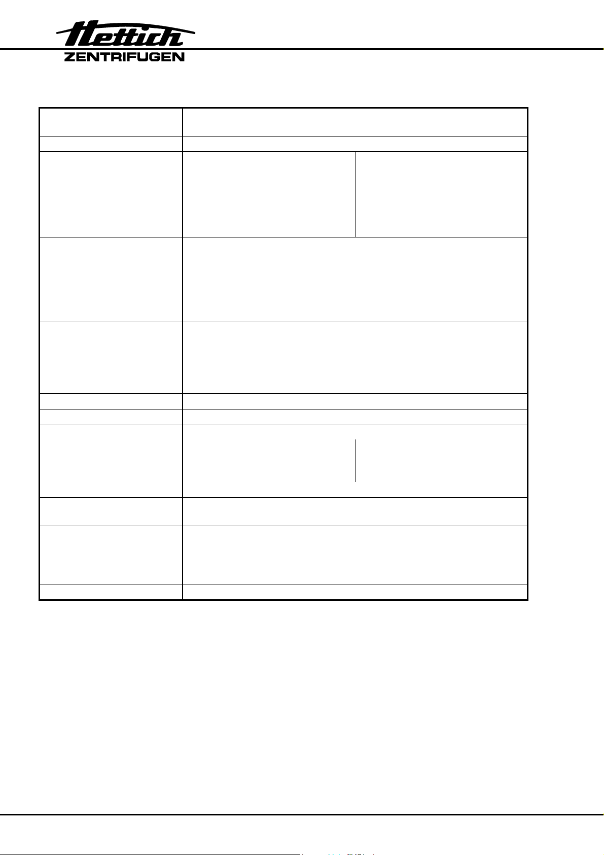
6 Technical datas
Manufacturer
Hettich Zentrifugen
D-78532 Tuttlingen
Model ROTOFIX 32
Product No. 1205 1205-01
Mains voltage (± 10%) 208 - 240 V 1∼ 100 - 127 V 1 ∼
Mains frequency 50 - 60 Hz 50 - 60 Hz
Connected load 300 VA 250 VA
Current consumption 1.3 A 2.4 A
Power consumption 160 W 165 W
Max. capacity 4 x 100 ml
Max. density 1.2 kg/dm3
Speed RPM 6000
Force RCF 4186
Kinetic energy 3000 Nm
Obligatory inspection no
Environment
− Ambient temperature
− Relative humidity
5°C up to 40°C
max. 80% to 31°C,
descending in a linear pattern
down to 50% at 40°C
Sample overtemp.
Class of protection
≤ 15 K
Ι
EMC ISM (Industrial Science Medicine)
− Emission
(Radio interference
suppression)
− Immunity
Noise level
(dependent on rotor)
EN 55011
Class B
according to EN 50082-1
FCC
Class B
≤ 65 dB(A)
Dimensions
• Width
• Depth
• Height
368 mm
437 mm
261 mm
Weight approx. 15.6 kg
4
Page 9

7 Space requirement
• According to the laboratory instrument standards EN 61010-2-20 an emergency
switch to separate power supply in the event of a failure must be installed in the
building electrical system.
This switch has to be placed remote from the centrifuge, prefered outside of the
room in which the centrifuge is installed or near by the exit of this room.
• The necessary space requirement can be found under Dimensions in the Technical
data chapter.
• The centrifuge must be set up in a suitable place, so that it is stable. During set up
the required safety area of 300 mm around the centrifuge, in accordance with IEC
1010-2-2, must be observed.
Persons and hazardous materials must not be located in the safety area whilst
the centrifuge is in operation.
• Do not place any object in front of the ventiduct.
− Keep a ventilation area of 300 mm around the ventiduct.
8 Connection to the mains
• Check whether the supply voltage, supply frequency and on-site mains fuse agree
with the specification on the nameplate. The nameplate is located on the back of the
centrifuge.
• Make sure that the mains switch is in the “0” position.
• The centrifuge must be connected to a standard mains socket using the power
supply cable provided.
9 Commissioning
• Check that the centrifuge has been properly set up and that the electrical
connections are correct (see Connection to the Mains and Space Requirement).
• Switch the mains switch “ON”, switch position “I”.
After a short time the control panel will switch on and the last set parameters will
appear in the displays.
• When the symbol has lit up, the lid can be opened.
• Open the lid and remove the transport protection (see Transport Protection
information sheet).
10 Opening the lid
• When the symbol has lit up, the lid can be unlocked and opened.
• Unlock the lid by turning the swivel clamp upwards.
• The symbol appears.
• Open the lid.
The lid can only be opened if the centrifuge is switched on and the rotor is
stationary.
If this is not possible, see chapter “ Emergency release “.
5
Page 10

11 Fitting / arming the rotor
• To fit the rotor, please see the B32 Rotor Instructions provided, or the section
“ Changing the rotor ”.
• In the case of rotors with swinging suspension fittings, all rotor positions must be
occupied.
Empty rotor positions are not permissible.
• Always fill the centrifuge containers outside the centrifuge.
• Ensure, by eye, that the containers are filled to a uniform level.
• Load positions located opposite one another equally.
For permitted combinations, see the “Rotors and Accessories” chapter in the
appendix.
• Ensure that the rotor is correctly positioned and secured.
• Close the lid by turning the handle downwards. When the
rotation display, the lid is correctly locked.
At each start, the rotor code of the rotor used is read in.
At each rotor change, the centrifuge stops after a few rotations and the rotor code is
shown in the display again. Centrifuging can be continued by repeatedly pressing the
START key (see Rotor Recognition chapter).
symbol lights up in the
6
Page 11
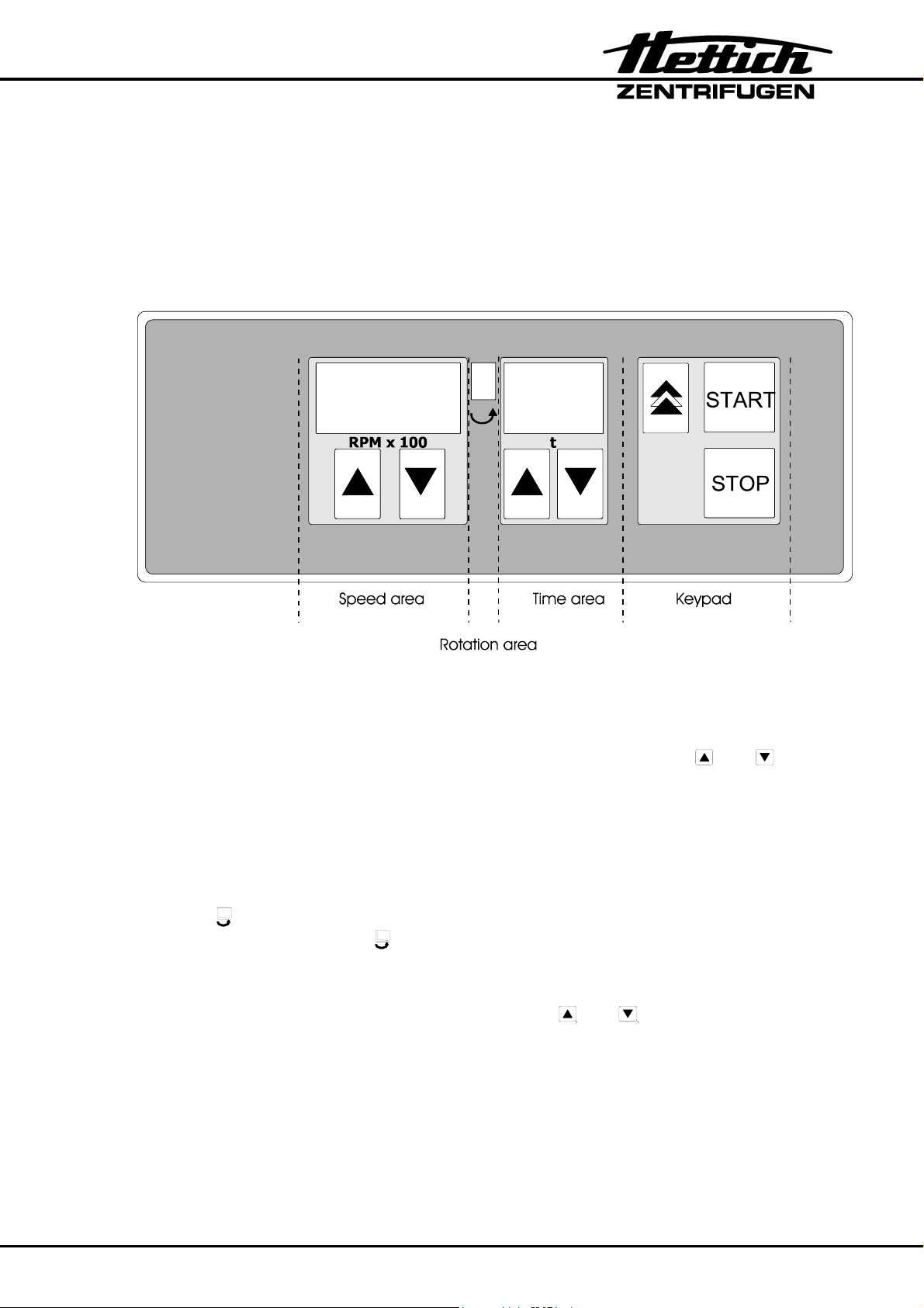
12 Control panel
The control panel is divided into four areas.
• Speed
• Rotation display
• Time
• Keys
12.1 Speed area
The speed area contains the speed display which indicates the preselected speed or
the ACTUAL speed during operation.
The speed can be preselected or changed during operation with the
keys. At the end of operation, the display flashes in seconds until the lid is opened or a
key is activated.
12.2 Rotation area
The rotation area contains the rotation display, which illuminates and rotates anticlockwise whilst the rotor is turning.
When the
When the lid is unlocked, the symbol lights up.
12.3 Time area
This area contains the running time display and the and arrows, with which the
switch-on time can be preselected or changed during operation.
When stationary, the preselected switch-on time is displayed, as well as the remaining
run time during operation. The decimal point flashes each second during operation.
At the end of operation, the display flashes each second until the lid is opened or a key
is activated.
symbols lights up, the rotor is stationary and the lid can be opened.
and arrow
7
Page 12
.
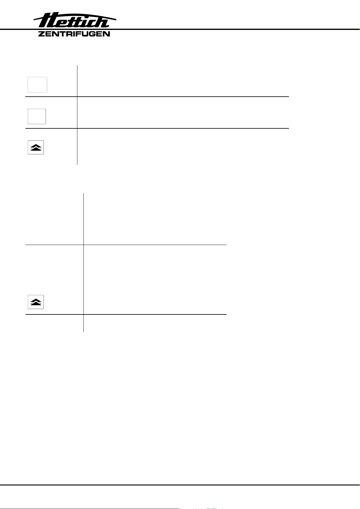
12.4 Key area
Start key
START
To start a run with the preselected parameters.
Stop key
The STOP key allows a centrifuging run to be stopped at any
time.
STOP
.
Pulse key
Brief centrifuging whilst the key is pressed down.
The run time is displayed in seconds in the run time display.
After 60 seconds, the run time is displayed in minutes.
13 Adjustable parameters
Speed
• min. speed 500 rpm
• max. speed 6000 rpm
• in steps of 100 rpm
Adjustable up to max. speed of the rotor
used.
Time
”—”
• min. preset time 1 min
• max. preset time 99 min
• in steps of 1 min
or
• continuous operation
or
• pulse ( short-time )
Braking force
• full braking effect
• low braking effect
8
Page 13
14 Preselecting centrifuging parameters or changing them during operation.
14.1 Speed
Each time the and arrow keys are activated, the speed is changed by 100 rpm. If
an arrow key is kept pressed down for longer, the speed is changed at an increasing
rate.
If the speed is changed during operation, this becomes effective immediately, i.e. the
speed is adjusted.
14.2 - of denser substances
The rotors are designed to centrifuge substances up to a maximum mean homogenous
density of 1.2 kg/dm3 when rotating at the stated speed.
Denser substances must be centrifuged at lower speed.
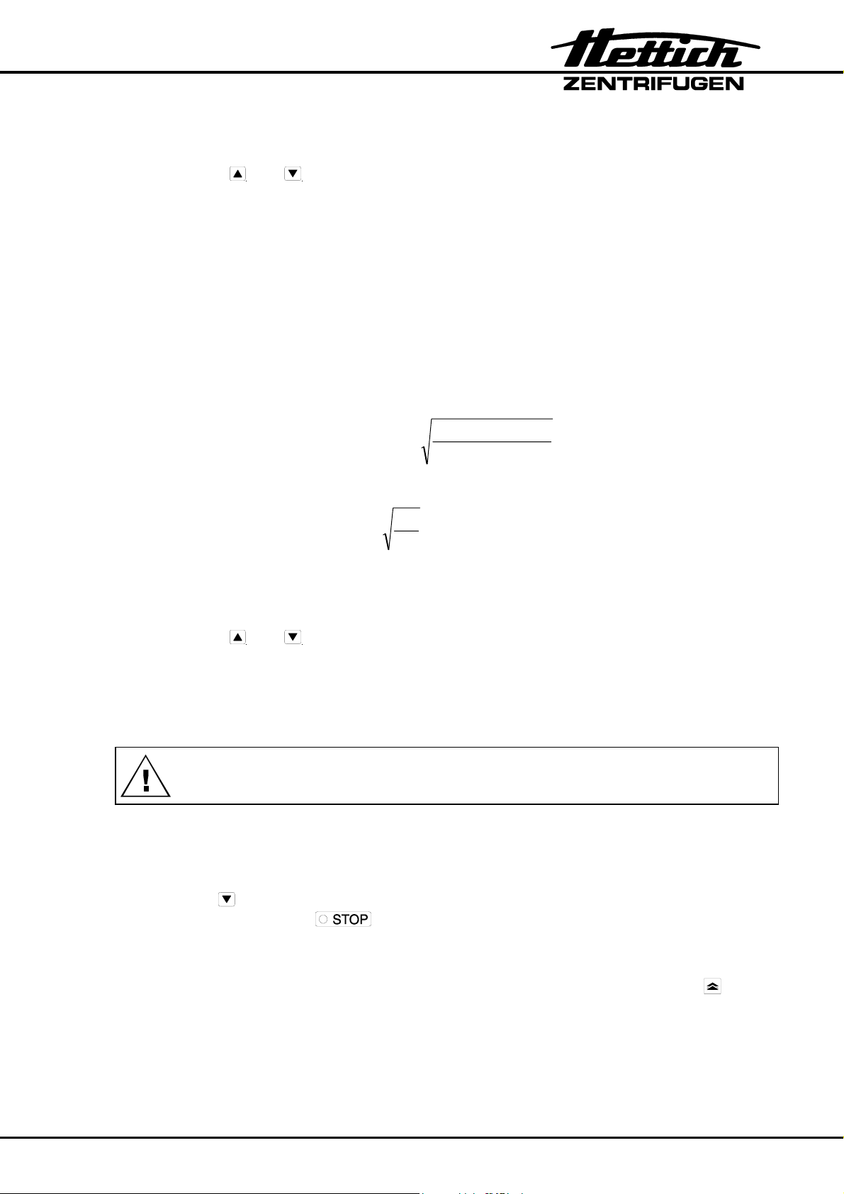
The permissible speed can be calculated using the following formula:
= )(n speed Reduced red
1.2
speed Rated x
density Greater
e.g.: RPM 4000, density 1.6 kg/dm
3
1.2
red
= n
RPM 3464 = 4000 x
1.6
If in doubt you should obtain clarification from the manufacturer.
14.3 Run time
Each time the and arrow keys are activated, the run time is changed by 1 minute.
If an arrow key is kept pressed down for longer, the run time is changed in minute steps,
at an increasing rate.
If the run time is changed during operation, this becomes effective immediately, i.e. the
remaining run time is adjusted.
If an arrow key is activated during operation, the run time or speed is adjusted
accordingly.
14.3.1 Continuous operation
The centrifuge can be operated in continuous operation. Continuous operation is set by
pressing the
stopped by activating the
arrow key until “ – ” appears in the run time display. Operation is only
.
key.
14.3.2 Pulsed operation
For brief centrifuging. The rotor turns at the preselected speed as long as the key is
pressed down.
9
Page 14
.
.
14.4 Brake adjustment
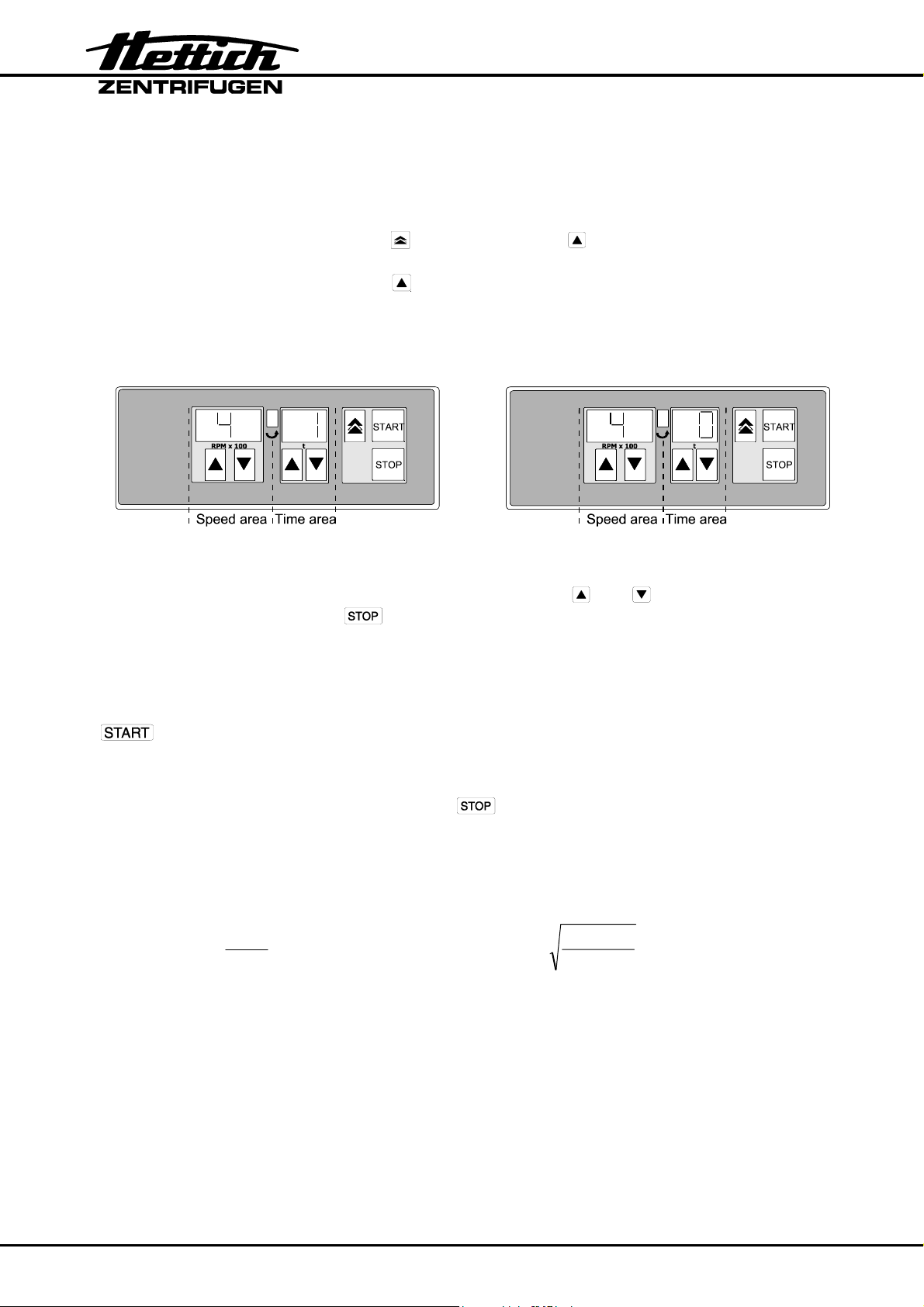
With this centrifuge, the braking effect can be set to normal or low.
This can be set before a run, as follows:
1. Switch off the mains switch
2. Simultaneously press the pulse key
and the arrow key in the speed area and
switch on the mains switch. Release the keys again.
3. If required press the arrow button
in the speed field until the depicted display
appears.
In the speed field the machine version as set by the factory and in the time field the
brake setting.
Normal braking effect “1” Low braking effect “0”
4. Set the required value, “1” or “0”, in the time area with the
5. Confirm the set value with the
key.
and arrow keys.
See Rotors and Accessories in the Braking Times chapter.
14.5 Start centrifuging run
After setting the centrifuging parameters, start the centrifuge by pressing the
.
key.
14.6 End centrifuging run
A centrifuging run is ended by pressing the
key or after expiry of the set run
time.
15 Calculating rotational speed RPM and relative centrifugal force RCF
These values are calculated using the formulas below:
RPM
= RCF
1000
2
1.118 x r x
RCF
= RPM
1000 x
1.118 x r
RCF = Relative centrifugal force
RPM = Rotational speed (revolutions per minute)
r = Radius in mm = Distance from the centre of the axle to the floor of the
centrifuge container. For further details on radius see
“Rotor and accessories” section.
10
Page 15
16 Changing the rotor
• Open the lid.
• Loosen the rotor tensioning nut by turning it counter-clockwise with the appropriate
spanner (see delivery checklist) until the release point is reached. Once this point is
passed, the rotor frees itself from the motor-shaft cone. Continue turning the nut until
the rotor can be lifted off the motor shaft.
• Clean the motor shaft and then lightly grease.
• Place the new rotor vertically on the motor shaft. The motor-shaft carrier pin must be
located in the groove on the rotor.
• Tighten the tensioning nut.
• Check that the rotor is seated securely.
17 Rotor identification
• Each time a centrifuging run is started, the centrifuge recognises the rotor code of the
installed rotor with the help of a sensor. This means that the nominal speed of the
installed rotor cannot be exceeded.
• After the identification of a newly installed rotor the drive will cut off and its rotor code
"rot ..." will be displayed. Example: rot 3 = rotor code 3.
.
• Press the
key.
• If the speed rating of the newly installed rotor is lower than the last speed entered,
the speed rating of the newly installed rotor will be displayed.
If the speed rating of the newly installed rotor is higher than the last speed entered,
the last speed entered will be displayed.
.
• Press the
key.
• Any speed up to the rated speed of the rotor can be entered while the centrifuge is
running.
If no rotor is fitted and the centrifuge is started, the centrifuge stops after a few
rotations and the error message – F – appears in the display
(to reset the error message, see Fault Table).
18 Emergency release
If loss of current or a centrifuge fault occurs while the centrifuge is running, the lid
remains locked.
To release in an emergency, unplug the centrifuge from the mains.
Wait for the rotor to stop turning before opening the lid.
Insert the release pin (see scope of supply) horizontally into the hole located at the top
right of the front panel. Push the release pin as far as the stop. Push the tip of the pin
down, at the same time swielling the hand grip upwards. Open the lid.
11
Page 16
19 Care / maintenance
Before applying any cleaning or disinfecting procedure other than those
recommended by the manufacturer, the user should contact the manufacturer
to make sure that the planned process will not damage the equipment.
• The centrifuge should be cleaned regularly for reasons of hygiene, and if necessary
should also be cleaned with soap or a mild cleaning agent.
• Any adherent impurities should be removed as they can cause corrosion.
• Humidity in the air or centrifuge containers with no hermetic seal can lead to
condensation. The centrifuge chamber should therefore be cleaned regularly with a
cloth or similar.
• For instructions on how to clean the rotor and accessories see the rotor instructions
B032.
• In the case of glass breakage, the fragments of glass along with any spilt centrifuge
product should be removed carefully from the centrifuge chamber, the containers or
container drill holes.
After a glass breakage the rubber inserts for the containers must be replaced
because any residual glass fragments in these inserts can cause further glass
breakage.
• If any infectious material should find its way into the centrifuge chamber it should be
disinfected immediately.
• When a biosafety system is in use (see section “Rotors and accessories”), the
bioseal (packing ring) between the hangers and the lid must be checked and cleaned
regularly. This routine should be performed at least once a week.
The packing ring should be replaced as soon as any signs of tears, brittleness or
wear are shown.
19.1 Supporting lugs
The supporting lugs on the rotor must always be well lubricated (use Hettich lubricating
grease no. 4051). Only when the supporting lugs are lubricated can it be guaranteed
that the hangers will swing out evenly and that the centrifuge will not cut out during
operation.
20 Faults
20.1 Note on faults
• If any fault or defect should arise, this is indicated by a symbol on the screen.
• The drive cuts out. Depending on the error message the run-down is either with or
without braking. After the rotor has come to rest, clearance for opening the lid is
issued.
MAINS RESET: - Mains switch OFF for longer than 10 secs.
- Mains switch ON.
If the fault cannot be rectifield by following the troubleshooting guide and if the error
message reappears after performing a MAINS RESET, you should contact Customer
Services.
12
Page 17
.
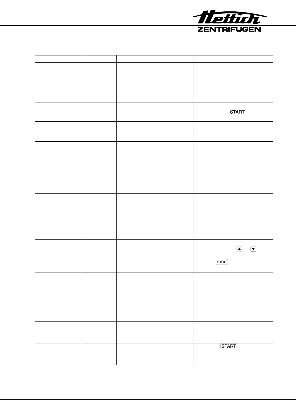
20.2 Fault table
Fault Display Cause of fault Remedy
No display --- No voltage
Triggering of the excess
current cut-out.
Tacho error - 1 - Failure of speed impulses
during operation,
Unbraked runout.
System reset - 2 - Failure of power supply during
a run
Unbraked runout.
Balance error - 3 - Balance error on the motor
axis due to weight differences
in the rotor loading.
Communication - 4 - Fault in control unit or power
unit. Unbraked runout.
Overload - 5 - Motor or motor control
defective.
Overvoltage
Undervoltage
- 6 -
- 8 -
Supply voltage outside
tolerance (see Technical
Data)
Unbraked runout.
Overspeed - 7 - Fault in the supply board
Unbraked runout
Excess
temperature
- 9 - Excess temperature switch in
motor has triggered.
Unbraked runout.
Version error No display in
speed field;
figure in time
Incorrect machine version set,
control unit jumps into Setting
menu.
field.
Controller
watchdog
- C - Fault in control unit
Unbraked runout.
Lid error - d - Unbraked rundown,
after standstill lid release
• Check distribution voltage.
• Check fuses.
• Mains switch ON
• Wait 120 sec. delay time.
• Perform mains reset.
• When stationary, open lid
and press
• Open lid when rotor is
stationary.
• Eliminate balance error.
• Perform mains reset when
stationary.
• Perform mains reset when
stationary.
• Perform mains reset when
stationary.
• Check supply voltage.
• Perform mains reset when
stationary
• When rotor is stationary,
open lid using emergency
unlocking (see Emergency
Unlocking chapter).
• Allow motor to cool down.
• Set the figure 4 in the time
field with the
arrow keys and confirm
with
• Perform mains reset.
• Perform mains reset when
stationary.
• Perform mains reset after
standstill.
.
key.
or
Short circuit - E - Short circuit in control unit /
power unit.
No rotor code - F - No rotor recognition at start.
No rotor fitted or defective
• Perform mains reset when
stationary.
• Perform mains reset when
stationary.
tacho.
New rotor
rot ... see section rotor identification
• Press
.
key.
identified
13
Page 18
21 Repairs
Repairs must only be carried out by personnel authorised to do so by the
manufacturer.
22 Customer Services / Servicing
Should your centrifuge break down or develop a fault, it should not be touched by
anyone except an engineer authorised by the manufacturers.
In such a case you should contact Hettich Customer Services.
Before contacting our Customer Services department you should make a note of the
following:
1. Centrifuge model
2. The factory number
Both of these numbers can be found on the centrifuge’s model plate.
Note down any problems experienced.
You must follow the steps above in order to return to normal operation as quickly as
possible.
23 Acceptance of the centrifuges for repair
If the centrifuge is returned to the manufacturer for repair, it must be decontaminated
and cleaned to protect persons, environment and material.
We reserve the right to accept contaminated centrifuges.
Costs incurred for cleaning and disinfection are to be charged to the customer.
We ask for your understanding in this matter.
You will find further information on our homepage: http://www.HettichLab.com
14
Page 19
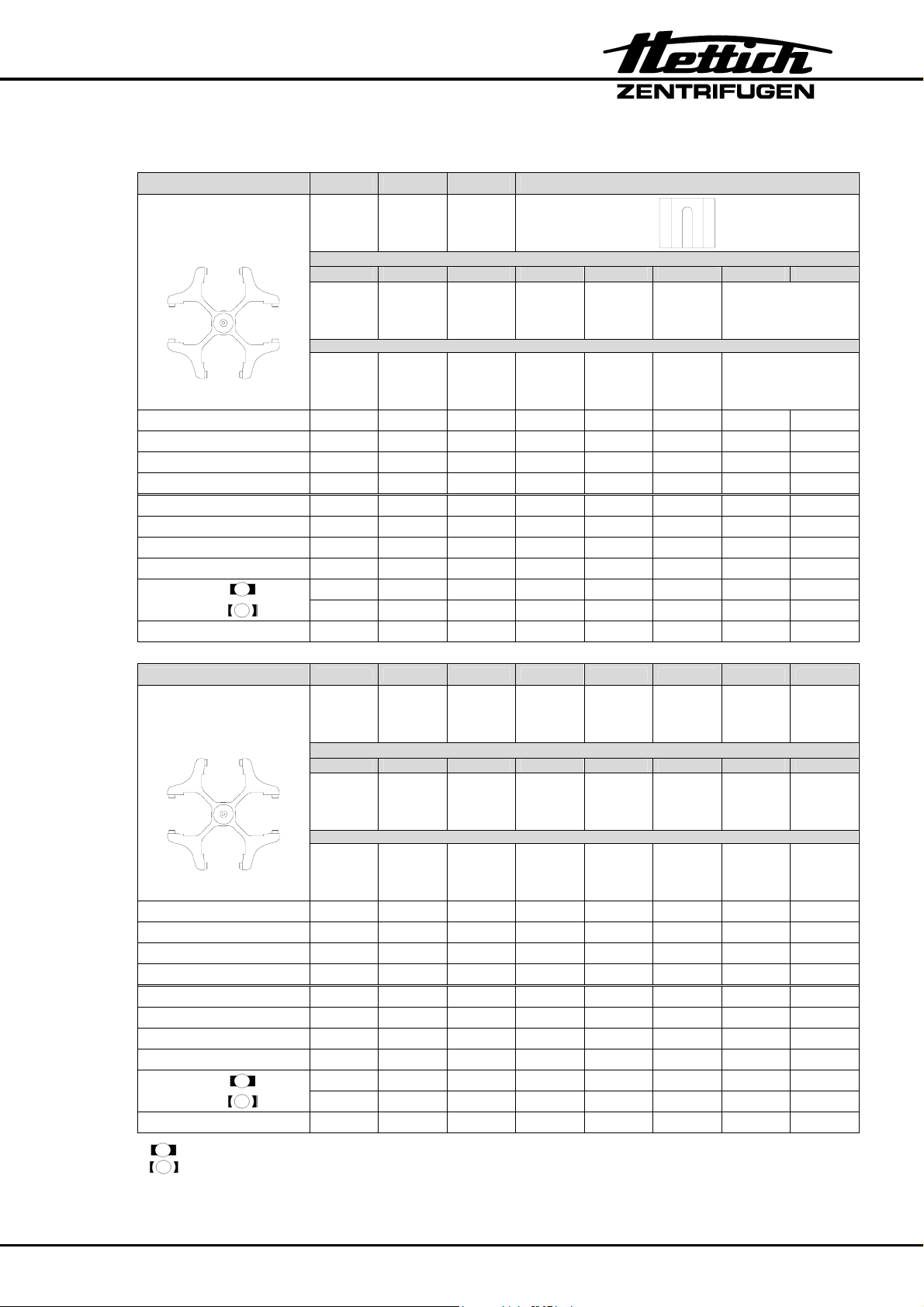
24 Rotors and accessories
Order no. 1624 1308 1345 1346 1366
Swing-out rotor
4-times
Capacity ml 50 45 20 4 3 1 1,5 2,0
Dimensions ∅ x L
Number per Frame 1 1 2 12 12 30 9 9
Number per Rotor 4 4 8 48 48 120 36 36
Speed RPM 4000 4000 4000 4000 4000 4000 4000 4000
RCF 2325 2451 2361 1932 1932 1950 1968 1968
Radius mm 130 137 132 108 108 109 110 110
Run-up time (97%) sec 22 22 22 22 22 22 22 22
Run-down
time
Temperature °C
mm 34 x 100 31 x 100 21 x 100 12 x 60 10 x 60 6 x 45 11 x 38 11 x 38
sec 25 25 25 25 25 25 25 25
sec 110 110 110 110 110 110 110 110
1)
Glass
Reaction tubes
1326 1327 1357 5277
Reduction
Tubes
Rhesus
Order no. 1624 1369 1369-91 1369-92 1370 1372
Swing-out rotor
4-times
Capacity ml 15 5 7 9 5
Dimensions ∅ x L
Number per Frame 4 4 4 5 17
Number per Rotor 16 16 16 20 68
Speed RPM 4000 4000 4000 4000 4000
RCF 2361 2236 2361 2361 2164
Radius mm 132 125 132 132 121
Run-up time (97%) sec 22 22 22 22 22
Run-down
time
Temperature °C
normal braking effect (1)
low braking effect (0)
mm 17 x 100 12 x 75 12 x 100 14 x 100 12 x 75
sec 25 25 25 25 25
sec 110 110 110 110 110
1)
Reduction
Tubes
1) The lowest possible temperature during the highest revolutions
and 1 hour running time (only in a cooled centrifuge)
15
Page 20
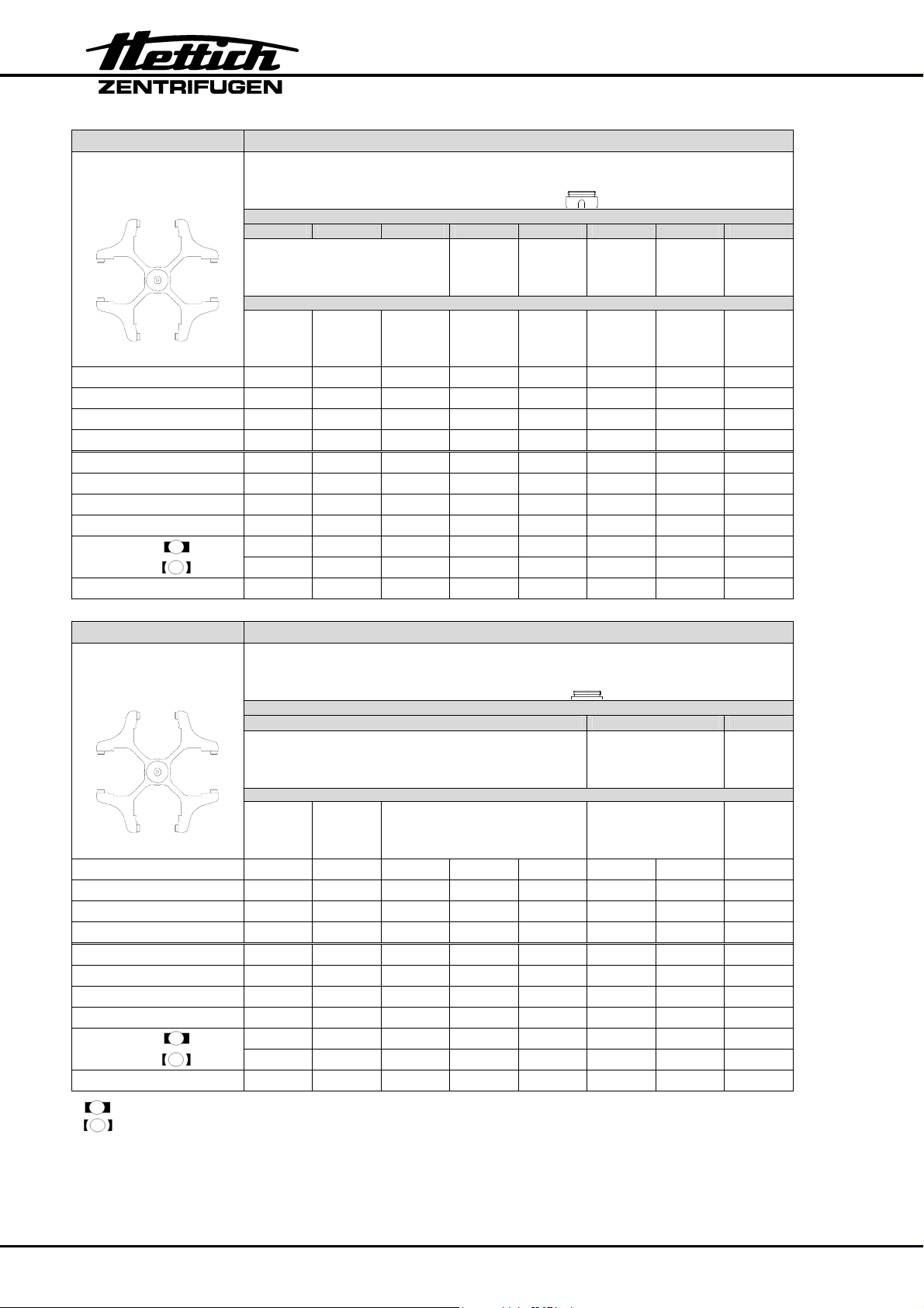
Order no. 1624 1382 1381
Swing-out rotor
4-times
1329 1330 1331 1339 1343 1347
Reduction
Tubes
Capacity ml 9 15 9-10 25 50 1 3 15
Dimensions ∅ x L
Number per Frame 4 4 4 1 1 27 9 1
Number per Rotor 16 16 16 4 4 108 36 4
Speed RPM 4000 4000 4000 4000 4000 4000 4000 4000
RCF 2540 2540 2540 2433 2397 2594 2630 2665
Radius mm 142 142 142 136 134 145 147 149
Run-up time (97%) sec 22 22 22 22 22 22 22 22
Run-down
time
Temperature °C
mm 14 x 100 17 x 100 16,5 x 92 24 x 100 34 x 100 6 x 45 10 x 60 17 x 120
sec 25 25 25 25 25 25 25 25
sec 110 110 110 110 110 110 110 110
1)
Sarstedt Falcon
Order no. 1624 1382 1381
Swing-out rotor
4-times
1348 1351
Reduction
Tubes
Capacity ml 10 4,0 – 5,5 7 9,5 - 10 8,5 –10 1,5 2,0
Dimensions ∅ x L
Number per Frame 4 4 4 4 4 5 5
Number per Rotor 16 16 16 16 16 20 20
Speed RPM 4000 4000 4000 4000 4000 4000 4000
RCF 2522 2522 2522 2522 2522 2451 2451
Radius mm 141 141 141 141 141 137 137
Run-up time (97%) sec 22 22 22 22 22 22 22
Run-down
time
Temperature °C
normal braking effect (1)
low braking effect (0)
mm 16 x 80 15,3 x 75 16 x 75 16 x 100 16 x 100 11 x 38 11 x 38
sec 25 25 25 25 25 25 25
sec 110 110 110 110 110 110 110
1)
Sarstedt Vacutainer Reaction tubes
1) The lowest possible temperature during the highest revolutions
and 1 hour running time t (only in a cooled centrifuge)
16
Page 21
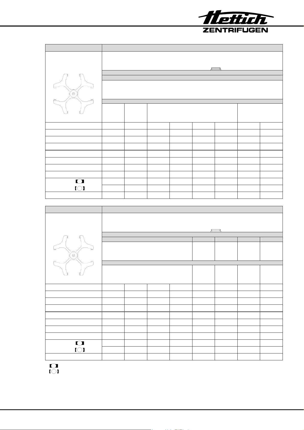
Order no. 1624 1382 1381
Swing-out rotor
4-times
Reduction
1383
Tubes
Capacity ml 6 7 4,9 4,5 – 5,0 2,0 – 3,0 2,6 – 2,9 2,0 – 5,0 1,6 – 5,0
Dimensions ∅ x L
Number per Frame 5 5 5 5 5 5 5 5
Number per Rotor 20 20 20 20 20 20 20 20
Speed RPM 4000 4000 4000 4000 4000 4000 4000 4000
RCF 2558 2558 2558 2558 2558 2558 2558 2558
Radius mm 143 143 143 143 143 143 143 143
Run-up time (97%) sec 22 22 22 22 22 22 22 22
Run-down
time
Temperature °C
mm 12 x 82 12 x 100 13 x 90 11,5 x 92 11,5 x 66 13 x 65 13 x 75 13 x 75
sec 25 25 25 25 25 25 25 25
sec 110 110 110 110 110 110 110 110
1)
Sarstedt Vacutainer
Order no. 1624 1382 1381
Swing-out rotor
4-times
1383 1384 1396 1457
Reduction
Tubes
Capacity ml 4,5 – 6,0 2,0 – 4,0 4,5 – 7,0 4,0 – 6,0 50 85 1,1 – 1,4
Dimensions ∅ x L
Number per Frame 5 5 5 5 1 1 7
Number per Rotor 20 20 20 20 4 4 28
Speed RPM 4000 4000 4000 4000 4000 4000 4000
RCF 2558 2558 2558 2558 2665 2612 2576
Radius mm 143 143 143 143 149 146 144
Run-up time (97%) sec 22 22 22 22 22 22 22
Run-down
time
Temperature °C
normal braking effect (9)
low braking effect (0)
mm 13 x 100 13 x 75 13 x 100 13 x 100 29 x 115 38 x 106 8,5 x 66
sec 25 25 25 25 25 25 25
sec 110 110 110 110 110 110 110
1)
Vacutainer Falcon Sarstedt
1) The lowest possible temperature during the highest revolutions
and 1 hour running time (only in a cooled centrifuge)
17
Page 22
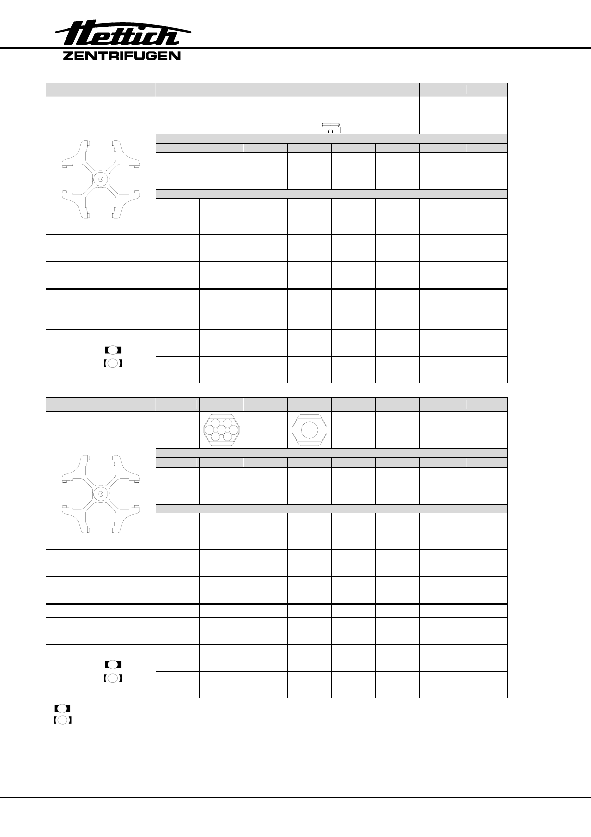
)
Order no. 1624 1382 1381
Swing-out rotor
4-times
Reduction
1459 4416 4417
Rubber
insert
Tubes
0761
0765
Rubber
insert
VK 0534
Chromium-b ath
tubes
Skal. 10µl-300µl,
15ml, 30ml
VK 0535
lid (rubber
Capacity ml 4,0 - 5,5 7,5 - 8,2 50 30 100 30
Dimensions ∅ x L
mm 15,3 x 75 15,3 x 92 29 x 107 26 x 95 44 x 100 44 x 105
Number per Frame 4 4 1 1 1 1
Number per Rotor 16 16 4 4 4 4
Speed RPM 4000 4000 4000 4000 4000 4000
RCF 2576 2576 2630 2451 2558 2558
Radius mm 144 144 147 137 143 143
Run-up time (97%) sec 22 22 22 22 22 22
Run-down
time
Temperature °C
sec 25 25 25 25 25 25
sec 110 110 110 110 110 110
1)
Order no. 1624 1741 1742 1745 1746
Swing-out rotor
4-times
Reduction
0701
Rubber
---- ---- ----
Inlay
Tubes
Capacity ml 9 15 25 50
Dimensions ∅ x L
mm 14 x 100 17 x 100 24 x 100 34 x 100
Number per Frame 10 7 2 1
Number per Rotor 40 28 8 4
Speed RPM 4000 4000 4000 4000
RCF 2415 2451 2451 2451
Radius mm 135 137 137 137
Run-up time (97%) sec 22 22 22 22
Run-down
time
Temperature °C
normal braking effect (1)
low braking effect (0)
sec 25 25 25 25
sec 110 110 110 110
1)
1) The lowest possible temperature during the highest revolutions
and 1 hour running time (only in a cooled centrifuge)
18
Page 23
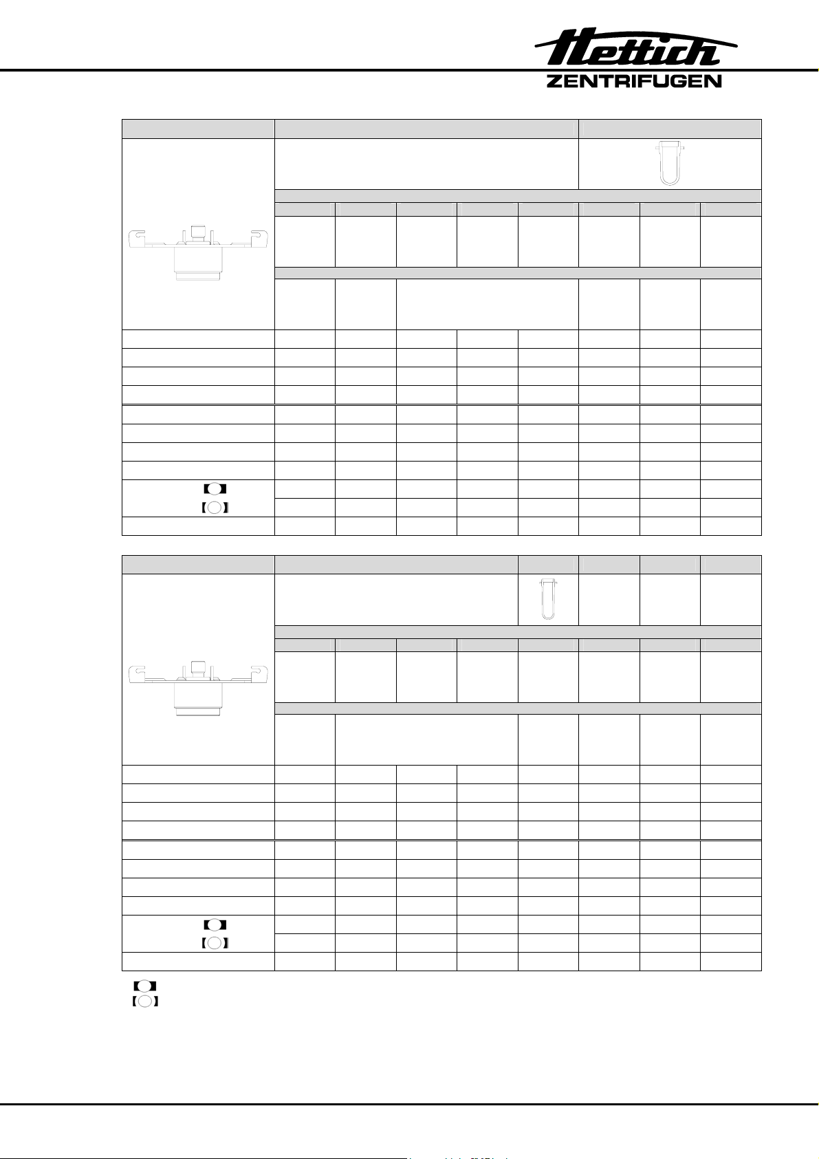
Order no. 1611 1131 1132
Angle -rotor
8-times (90°)
Capacity ml 5 2,6 – 2,9 2,0 – 4,0 1,6 – 5,0 2,0 – 5,0 10 4,0 – 5,5
Dimensions ∅ x L
Number per Frame 1 1 1 1 1 1 1
Number per Rotor 8 8 8 8 8 8 8
Speed RPM 4000 4000 4000 4000 4000 4000 4000
RCF 1914 1914 1914 1914 1914 1914 1914
Radius mm 107 107 107 107 107 107 107
Run-up time (97%) sec 22 22 22 22 22 22 22
Run-down
time
Temperature °C
mm 12 x 75 13 x 65 13 x 75 13 x 75 13 x 75 17 x 70 15,3 x 75
sec 25 25 25 25 25 25 25
sec 104 104 104 104 104 104 104
1)
Sarstedt Vacutainer Sarstedt
Reduction
Tubes
Order no. 1611 1643 1644
Angle -rotor
8-times (90°)
Capacity ml 7 4,0 – 6,0 4,5 – 7,0 4,5 – 6,0 15
Dimensions ∅ x L
Number per Frame 1 1 1 1 1
Number per Rotor 8 8 8 8 8
Speed RPM 4000 4000 4000 4000 4000
RCF 2415 2415 2415 2415 2415
Radius mm 135 135 135 135 135
Run-up time (97%) sec 22 22 22 22 22
Run-down
time
Temperature °C
normal braking effect (1)
low braking effect (0)
mm 12 x 100 13 x 100 13 x 100 13 x 100 17 x 100
sec 25 25 25 25 25
sec 104 104 104 104 104
1)
Vacutainer
1) The lowest possible temperature during the highest revolutions
and 1 hour running time (only in a cooled centrifuge)
Reduction
Tubes
19
Page 24
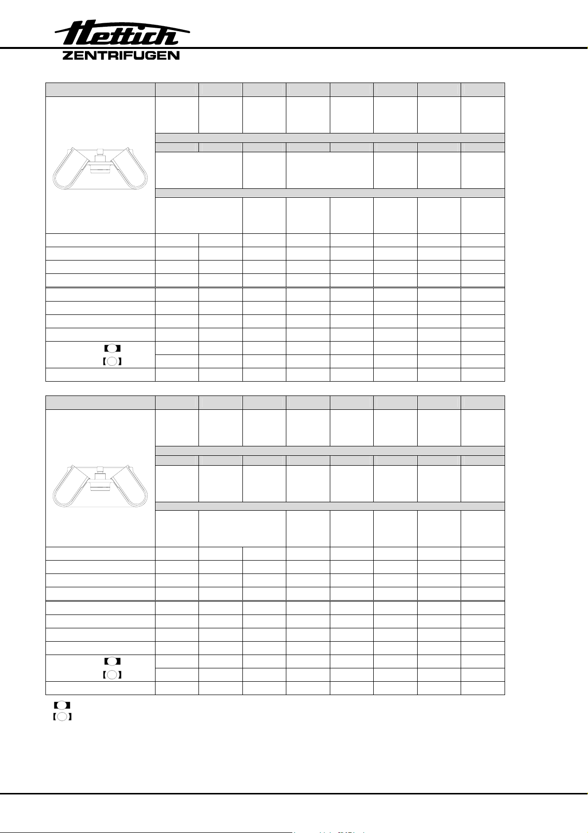
Order no. 1620A
Angle -rotor
6-times (35°)
Reduction
1449 1448 1451 1447 1446 1463
Tubes
Reaction tubes Sarstedt
Capacity ml 1,5 2,0 10 15 9-10 30 50 50
Dimensions ∅ x L
mm 11 x 38 11 x 38 16 x 80 17 x 100 16,5 x 92 26 x 95 29 x 107 35 x 105
Number per Frame 4 4 2 1 1 1 1 1
Number per Rotor 24 24 12 6 6 6 6 6
Speed RPM 6000 6000 6000 6000 6000 6000 6000 6000
RCF 4065 4065 3904 3904 3904 3824 4025 4146
Radius mm 101 101 97 97 97 95 100 103
Run-up time (97%) sec 19 19 19 19 19 19 19 19
Run-down
time
Temperature °C
sec 22 22 22 22 22 22 22 22
sec 104 104 104 104 104 104 104 104
1)
Order no. 1620A 1646
Falcon-Set
(for 6
tubes)
Reduction
Angle -rotor
6-times (35°)
---- 1464 ----
Tubes
Falcon
Capacity ml 85 15 50
Dimensions ∅ x L
mm 38 x 106 17 x 120 29 x 115
Number per Frame ---- 1 1
Number per Rotor 6 6 3
Speed RPM 6000 6000 6000
RCF 4186 3985 3985
Radius mm 104 104 104
Run-up time (97%) sec 19 19 19
Run-down
time
Temperature °C
normal braking effect (1)
low braking effect (0)
sec 22 22 22
Sec 104 104 104
1)
1) The lowest possible temperature during the highest revolutions
and 1 hour running time (only in a cooled centrifuge)
20
Page 25
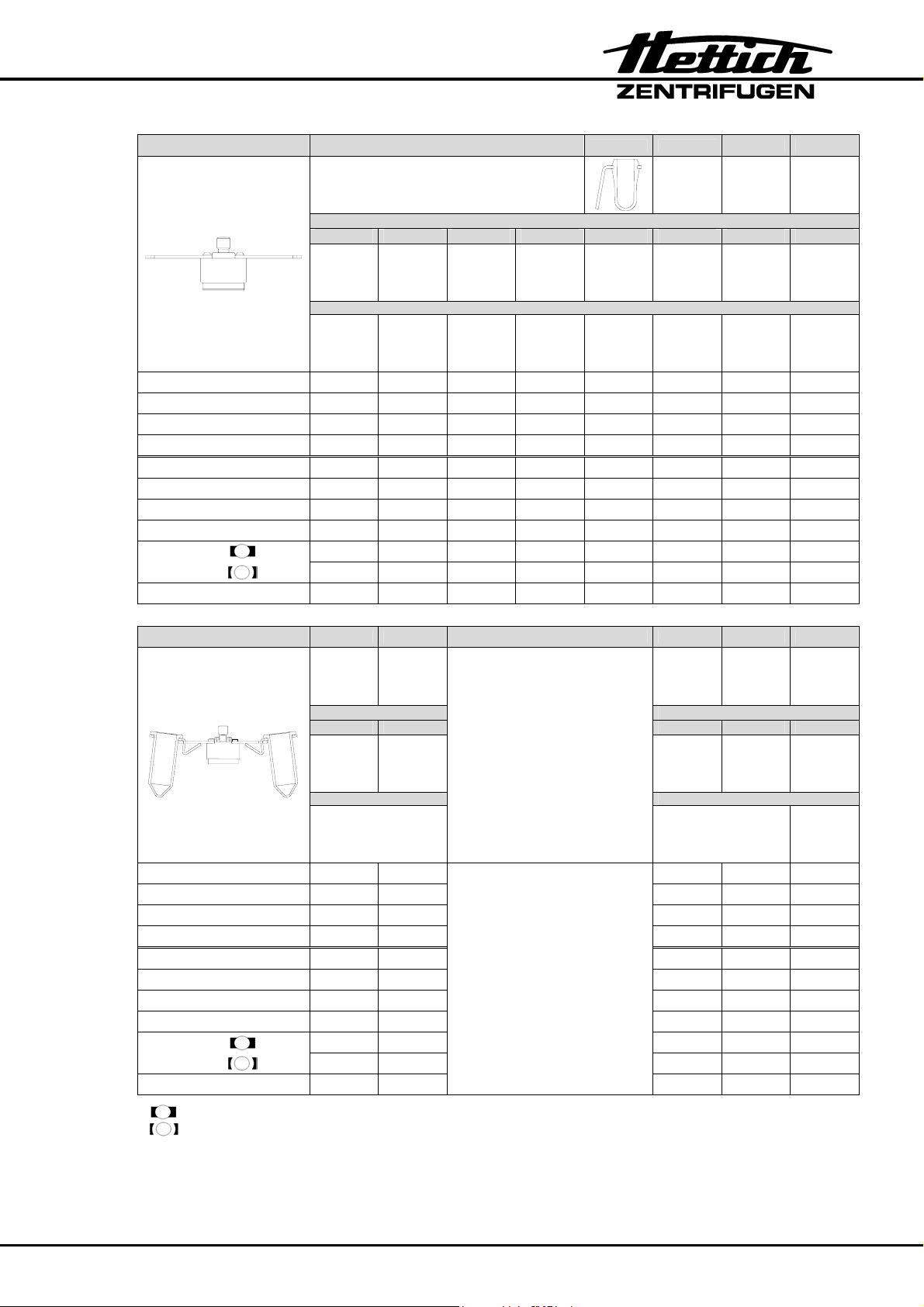
Order no. 1628 1127 (50°)
1122 (55°) 1621 (75°)
12-times (50°-75°)
Reduction
Tubes
Capacity ml 5 2,0 – 5,0 1,6 – 5,0 2,0 – 4,0 10 15
Dimensions ∅ x L
mm 12 x 75 13 x 75 13 x 75 13 x 75 17 x 70 17 x 100
Number per Frame 1 1 1 1 1 1
Number per Rotor 12 12 12 12 12 12
Speed RPM 4000 4000 4000 4000 4000 4000
RCF 2218 2218 2218 2218 2254 2683
Radius mm 124 124 124 124 126 150
Run-up time (97%) sec 22 22 22 22 22 22
Run-down
time
Temperature °C
sec 25 25 25 25 25 25
sec 110 110 110 110 110 110
1)
Order no. 1617 Order no. 1619
Swing-out rotor
6-times (90°)
Swing-out rotor
8-times (45°)
Reduction Reduction
1462 1462
Tubes Tubes
Falcon
Falcon
Capacity ml 15 50 15 15
Dimensions ∅ x L
mm 17 x 120 29 x 115 17 x 120 29 x 115
Number per Frame 1 1 1 1
Number per Rotor 8 8 6 6
Speed RPM 4000 4000 4000 4000
RCF 2469 2469 2701 2701
Radius mm 138 138 151 151
Run-up time (97%) sec 22 22 22 22
Run-down
time
Temperature °C
normal braking effect (1)
low braking effect (0)
sec 25 25 25 25
sec 110 110 110 110
1)
1) The lowest possible temperature during the highest revolutions
and 1 hour running time (only in a cooled centrifuge)
21
Page 26
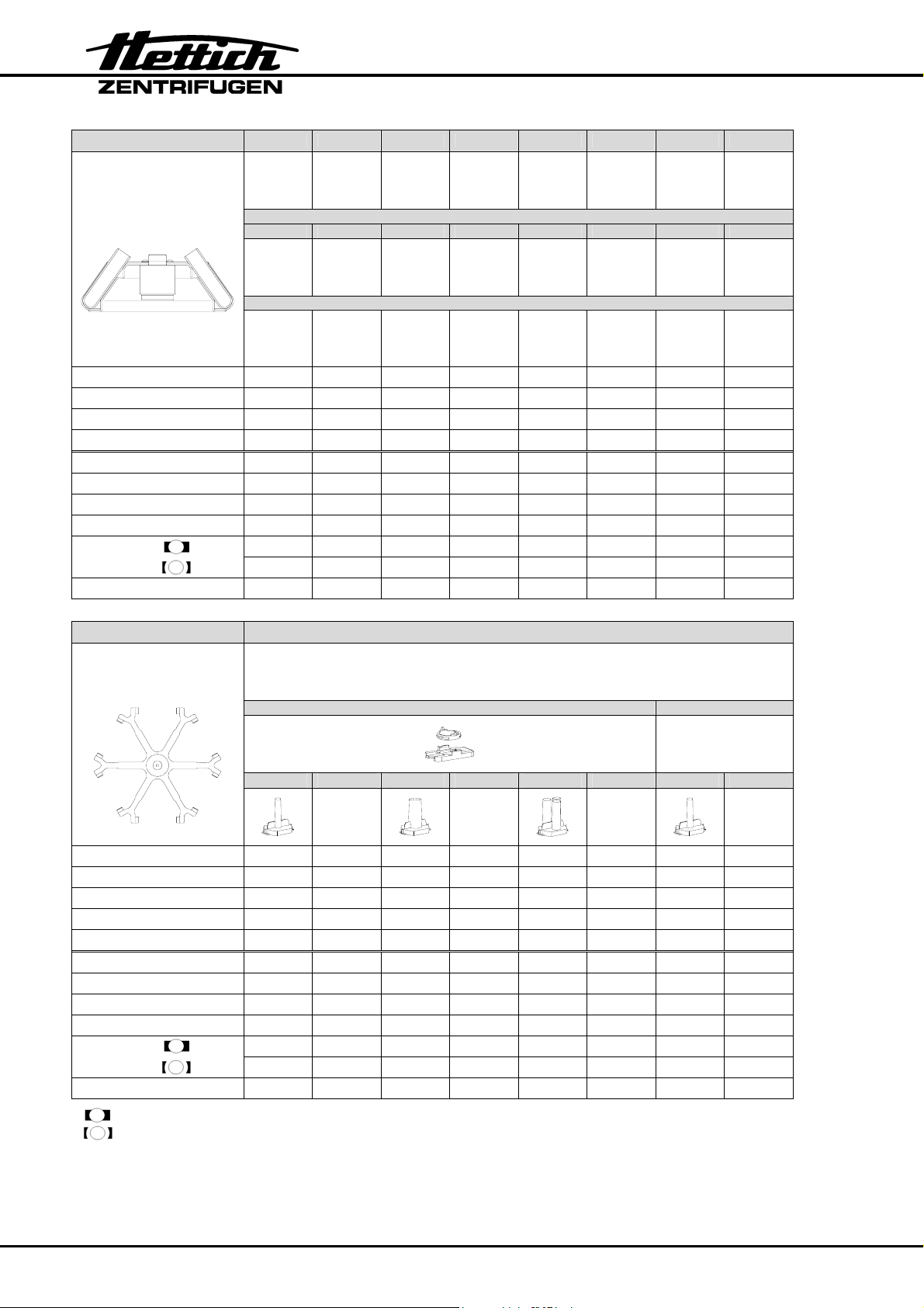
Order no. 1613
Angle -rotor r
12-times (35°)
Reduction
1056 --- ---
Tubes
Falcon
Capacity ml 5 15 15
Dimensions ∅ x L
mm 12 x 75 17 x 100 17 x 120
Number per Frame
Number per Rotor 12 12 6
Speed RPM 6000 6000 6000
RCF 3461 4105 4105
Radius mm 86 102 102
Run-up time (97%) sec 13 13 13
Run-down
time
Temperature °C
sec 15 15 15
sec 104 104 104
1)
Order no. 1626 1661 + 1660
Swing-out rotor
6-times
1662 1670
1663 1664 1665 1666 1667 1668 1663 1664
Filter Cards 1675 1675 1675 1676 1677 1678 1692 1692
Capacity ml 1 2 4 8 3 x 2 4 x 1 1 2
Dimensions ∅ / A
2
mm
6,2 x 30 8,7 x 60
12,4 x 120 17,5 x 240
8,7 x 60 6,2 x 30 6,2 x 30 8,7 x 60
Number per Frame 1 1 1 1 1 1 2 2
Number per Rotor 6 6 6 6 6 6 12 12
Speed RPM 4000 4000 4000 4000 4000 4000 4000 4000
RCF 2039 2039 2039 2039 2039 2039 2039 2039
Radius mm 114 114 114 114 114 114 114 114
Run-up time (97%) sec 22 22 22 22 22 22 22 22
Run-down
time
Temperature °C
normal braking effect (1)
low braking effect (0)
sec 25 25 25 25 25 25 25 25
sec 110 110 110 110 110 110 110 110
1)
1) The lowest possible temperature during the highest revolutions
and 1 hour running time (only in a cooled centrifuge)
2) Object carrier will not stand RCF values exceeding 1100
22
Page 27
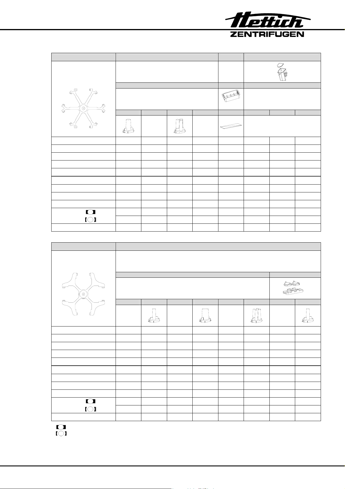
Order no. 1626 1661 + 1660 1660 1680
Swing-out rotor
6-times
1665 1666 1667 1668 1671 1672 1673
1670 1285 1662
only without lid
1661
Filter Cards 1692 1691 1694 1693
Capacity ml 4 8 3 x 2 4 x 1
Dimensions ∅ / A
2
12,4 x 120 17,5 x 240
mm
Object slide
[1] 1696
[2] 1676
[1] 0,3
[2] 1,5
[1] 1697
[2] 1676
[1] 0,3
[2] 1,25
[1] 1698
[2] 1676
[1] 0,3
[2] 0,75
8,7 x 60 6,2 x 30 26 x 76 6,2 / 30 8,7 / 60 12,4 / 120
Number per Frame 2 2 2 2 6 1 1 1
Number per Rotor 12 12 12 12 36 6 6 6
Speed RPM 4000 4000 4000 4000 4000 4000 4000 4000
RCF 2039 2039 2039 2039 1842 1842 1842
Radius mm 114 114 114 114 103 103 103
Run-up time (97%) sec 22 22 22 22 22 22 22
Run-down
time
Temperature °C
sec 25 25 25 25 25 25 25
sec 110 110 110 110 110 110 110
1)
Order no. 1624 1661 + 1660
Swing-out rotor
4-times
1663 1664 1665 1666 1667 1668 1663 1664
1662 1670
2)
Filter Cards 1675 1675 1675 1676 1677 1678 1692 1692
Capacity ml 1 2 4 8 3 x 2 4 x 1 1 2
Dimensions ∅ / A
2
mm
6,2 x 30 8,7 x 60
12,4 x 120 17,5 x 240
8,7 x 60 6,2 x 30 6,2 x 30 8,7 x 60
Number per Frame 1 1 1 1 1 1 2 2
Number per Rotor 4 4 4 4 4 4 8 8
Speed RPM 4000 4000 4000 4000 4000 4000 4000 4000
RCF 1646 1646 1646 1646 1646 1646 1646 1646
Radius mm 92 92 92 92 92 92 92 92
Run-up time (97%) sec 22 22 22 22 22 22 22 22
Run-down
time
Temperature °C
normal braking effect (1)
low braking effect (0)
[1] One-step-methode [2] Two-step-methode 2) Object carrier will not stand RCF values exceeding 1100
sec 25 25 25 25 25 25 25 25
sec 110 110 110 110 110 110 110 110
1)
1) The lowest possible temperature during the highest revolutions
and 1 hour running time (only in a cooled centrifuge)
23
Page 28
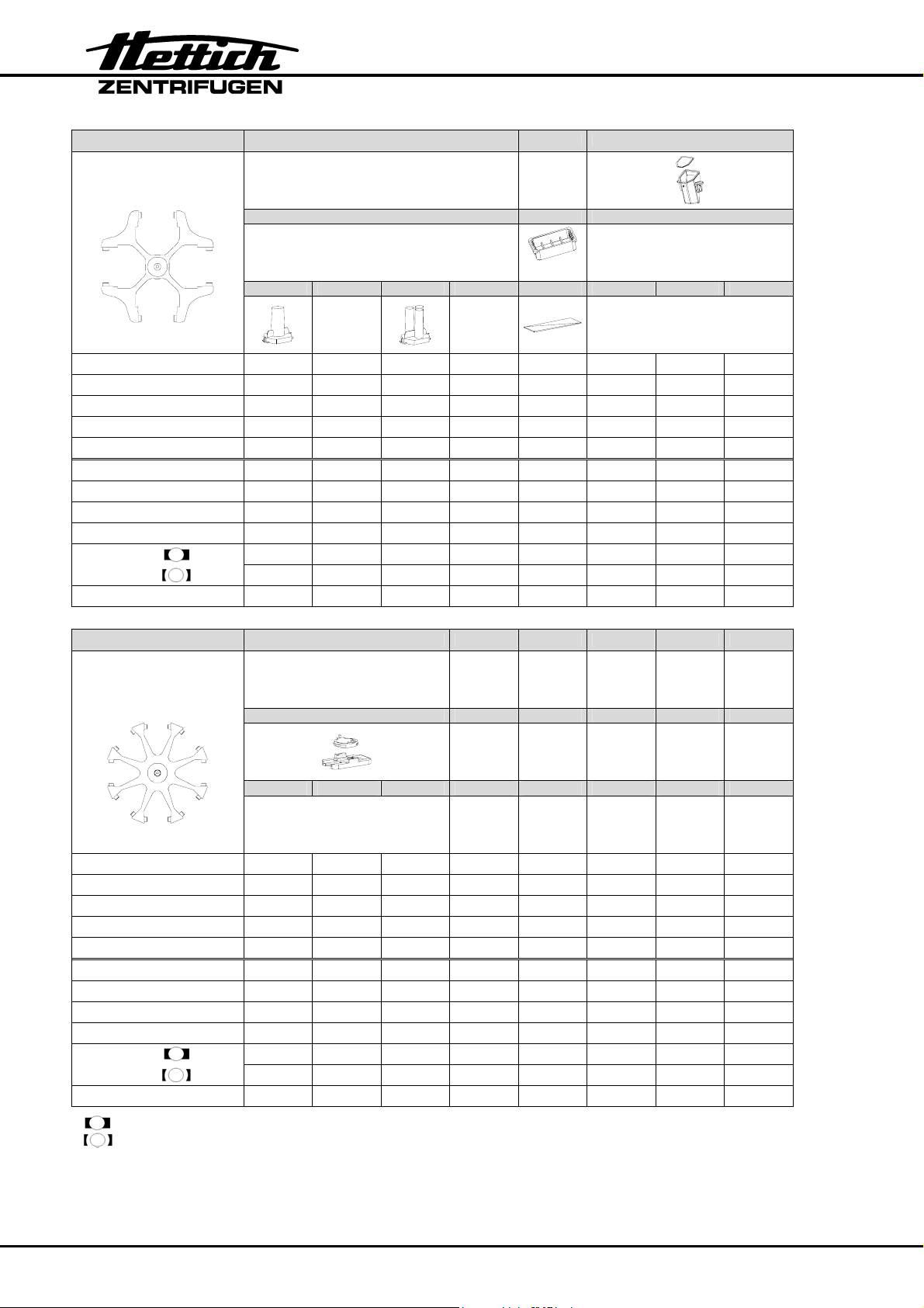
Order no. 1624 1661 + 1660 1660 1680
Swing-out rotor
4-times
1665 1666 1667 1668 1671 1672 1673
1670 1285 1662
only without lid
1661
Filter Cards 1692 1691 1694 1693
Capacity ml 4 8 3 x 2 4 x 1
Dimensions ∅ / A
2
12,4 x 120 17,5 x 240
mm
Object slide
[1] 1696
[2] 1676
[1] 0,3
[2] 1,5
[1] 1697
[2] 1676
[1] 0,3
[2] 1,25
[1] 1698
[2] 1676
[1] 0,3
[2] 0,75
8,7 x 60 6,2 x 30 26 x 76 6,2 / 30 8,7 / 60 12,4 / 120
Number per Frame 2 2 2 2 6 1 1 1
Number per Rotor 8 8 8 8 24 4 4 4
Speed RPM 4000 4000 4000 4000 4000 4000 4000 4000
RCF 1646 1646 1646 1646 1449 1449 1449
Radius mm 92 92 92 92 81 81 81
Run-up time (97%) sec 22 22 22 22 22 22 22
Run-down
time
Temperature °C
sec 25 25 25 25 25 25 25
sec 110 110 110 110 110 110 110
1)
Order no. 1648 1680
Swing-out rotor
8-times
1662
1671 1672 1673
Filter Cards
Capacity ml
Dimensions ∅ / A
mm
[1] 1696
[2] 1676
[1] 0,3
[2] 1,5
2
6,2 / 30 8,7 / 60 12,4 / 120
[1] 1697
[2] 1676
[1] 0,3
[2] 1,25
[1] 1698
[2] 1676
[1] 0,3
[2] 0,75
Number per Frame 1 1 1
Number per Rotor 8 8 8
Speed RPM 4000 4000 4000
RCF 2218 2218 2218
Radius mm 124 124 124
Run-up time (97%) sec 22 22 22
Run-down
time
Temperature °C
normal braking effect (1)
low braking effect (0)
[1] One-step-methode [2] Two-step-methode 2) Object carrier will not stand RCF values exceeding 1100
sec 28 28 28
sec 117 117 117
1)
1) The lowest possible temperature during the highest revolutions
and 1 hour running time (only in a cooled centrifuge)
Subject to alteration !
24
 Loading...