

Hettich Rotina 380R, Rotina 380 Repair instructions
ROTINA 380
ROTINA 380 R
11.08 Andreas Hettich GmbH & Co. KG AR1701EN
Repair instructions

Andreas Hettich GmbH & Co. KG
Föhrenstraße 12, D-78532 Tuttlingen / Germany
Phone (07461) 705-0
Fax (07461) 705-125
info@hettichlab.com, service@hettichlab.com
www.hettichlab.com
© 2008 by Andreas Hettich GmbH & Co. KG
All rights reserved. No part of this publication may be reproduced without the prior
written permission of the copyright owner.
Modifications reserved!
AR1701EN / 11.08
2/98

Contents
1 Introduction ..............................................................................................................6
2 Symbol meanings..................................................................................................... 6
3 Disposal ...................................................................................................................7
4 Description of the centrifuge.....................................................................................8
4.1 Block diagram of the control.............................................................................. 8
4.2 Operating panel (A2).........................................................................................9
4.3 Electronics ROTINA 380 (A1) resp. ROTINA 380 R (A1).................................9
4.4 Special features ..............................................................................................10
4.5 Brake resistor (R1)..........................................................................................10
4.6 Motor (M1) / Tacho system (B4, B2.1) ............................................................ 10
4.7 Imbalance sensor (B2.2) .................................................................................11
4.8 Motor-driven lid lock (A3) ................................................................................ 11
4.9 Cooling system................................................................................................11
4.10 Safety devices.................................................................................................12
5 Troubleshooting procedures...................................................................................12
6 Error messages...................................................................................................... 13
6.1 Perform a MAINS RESET ...............................................................................13
6.2 Brief description ..............................................................................................13
6.3 Description and elimination of errors............................................................... 16
7 Settings and interrogations.....................................................................................36
7.1 Summary of the possible settings and interrogations......................................36
7.2 Inquiry the system information ........................................................................37
7.3 Inquire and change the operating hours and inquire the number of the
centrifugation runs........................................................................................... 38
7.4 Set the acoustic signal .................................................................................... 39
7.5 Set the centrifugation data displayed after switch-on......................................41
7.6 Set the functions Ramp Unit, RCF-Integral, B-Ramp and Multi programs ......42
7.7 Set the address of the centrifuge ....................................................................42
7.8 Logging the occurred faults............................................................................. 43
7.9 Logging of certain procedures (events)........................................................... 46
7.10 Speed values during the centrifugation run..................................................... 48
7.11 Check both speed sensors.............................................................................. 49
7.12 Set the centrifuge model ................................................................................. 50
3/98

7.13 Blank the centrifuge model in the display ....................................................... 51
7.14 Cooling parameters ........................................................................................ 52
7.14.1 Set the temperature unit .......................................................................... 52
7.14.2 Inquire the temperature values ................................................................ 53
7.14.3 Deactivate the temperature sensor (B2) at the top of the
centrifuge chamber.................................................................................. 55
7.14.4 Compensate the temperature sensors .................................................... 56
7.15 Imbalance values............................................................................................ 58
7.15.1 Logging the maximum imbalance values................................................. 58
7.15.2 Inquiry the current and the maximum imbalance values.......................... 59
7.15.3 Setting the imbalance switch-off .............................................................. 60
7.16 Set the transmission rate (baud rate) of the serial interface............................ 62
7.17 Function test ................................................................................................... 63
7.18 Delete programs and program linking............................................................. 69
7.19 Display the contents of the memory cells of the EEPROM ............................. 70
7.20 Initialise the EEPROM .................................................................................... 71
7.21 Automatic repetition of the centrifugation run.................................................. 72
8 Update the software of the control processor ........................................................ 74
8.1 Install the flash-program on the PC ................................................................ 74
8.2 Perform a software update.............................................................................. 74
9 Functional check after a repair............................................................................... 76
10 General arrangement of the components........................................................... 77
11 Mounting and removing components ................................................................. 81
11.1 Removing the front panel................................................................................ 81
11.2 Removing the support sheet of the electronics (A1) ....................................... 81
11.3 Hook in the front panel at the support sheet for electronics (A1) .................... 82
11.4 Removing the upper part of the centrifuge housing ........................................ 82
11.5 Removing Motor (M1) / Rubber-metal bearings / Speed sensor
(B2.1, at the bottom of the motor) / Imbalance sensor (B2.2)......................... 83
11.6 Speed sensor (B4, on top of the motor).......................................................... 83
11.7 Motor-driven lid lock........................................................................................ 84
11.7.1 Removing the motor-driven lid lock ......................................................... 84
11.7.2 Replacing the left lid lock......................................................................... 84
11.7.3 Replacing the right lid lock....................................................................... 84
11.7.4 Replacing the eccentric disc.................................................................... 85
11.7.5 Replacing the sliding blocks .................................................................... 85
4/98

11.8 Electronics (A1)...............................................................................................86
11.9 Operating panel (A2)....................................................................................... 86
11.10 Rotary encoder (S1) .................................................................................... 87
11.11 Brake resistor (R1) with overtemperature switch......................................... 87
11.12 Temperature sensor (B1) at the bottom of the centrifuge chamber
(only in centrifuges with cooling)..................................................................87
11.13 Temperature sensor (B3) at the condenser (only in centrifuges
with cooling) ................................................................................................88
11.14 Fan (M3) at the condenser (only in centrifuges with cooling) ......................88
11.15 Fan (M5) for cooling the electronics (only in centrifuges with cooling)......... 88
11.16 Starting capacitor / starting relay (only in centrifuges with cooling) .............89
11.17 Mains switch (F1) ........................................................................................89
11.18 Appliance plug (A4 resp. A5)....................................................................... 89
11.19 Transformer (T1, only in 120 V version) ...................................................... 90
11.20 Circuit breaker (F2, only in 120 V version) ..................................................90
11.21 Packing ring................................................................................................. 90
11.22 Pneumatic spring.........................................................................................91
12 Technical documents..........................................................................................92
12.1 Tachometer code configuration of the rotors................................................... 92
12.2 Cooling diagram..............................................................................................93
12.3 Connecting diagram ........................................................................................95
12.3.1 Abbreviations of the cable colours ........................................................... 95
12.3.2 Connecting diagram ROTINA 380 / 380 R............................................... 96
12.4 Technical specifications .................................................................................. 98
5/98
1 Introduction
• Repairs must only be carried out by personnel authorised to do so by the
manufacturer.
Interventions and modifications at centrifuges, which have been conducted
by persons not authorized by the Andreas Hettich GmbH & Co. KG
company, are at their own risk and entail the loss off all guarantee and
liability claims. In such an event any guarantee claim or liability claim
against the Andreas Hettich GmbH & Co. KG company expire.
• Only original spare parts and original accessories licensed by the Andreas Hettich
GmbH & Co. KG company are allowed to be utilised.
If no original spare parts or no original accessories are used, any guarantee
claim or liability claim against the Andreas Hettich GmbH & Co. KG
company ceases to exist.
• Information about the operation of the centrifuge please see operating instructions.
• We reserve all rights for these technical documents.
2 Symbol meanings
Symbol on the machine:
Attention, general hazard area.
Before using the centrifuge implicitly read the operating instructions and pay
attention to the safety relevant references!
Symbol in this document:
Attention, general hazard area.
This symbol refers to safety relevant warnings and indicates possibly
dangerous situations.
The non-adherence to these warnings can lead to material damage and injury
to personal.
Symbol in this document:
Warning! Danger for human lives by electric shock.
Symbol on the machine and in this document:
Beware of hot surface.
Symbol on the machine and in this document:
Plastic suspension can only be used in temperatures up to a maximum of
40°C / 104°F.
Symbol on the machine:
Equipotential: Connector (PE connector) for potential equalization (only for
centrifuge with PE connector).
6/98
Symbol in this document:
This symbol refers to important circumstances.
Symbol on the machine and in this document:
Symbol for the separate collection of electric and electronic devices according
to the guideline 2002/96/EG (WEEE). The device belongs to Group 8 (medical
devices).
Applies in the countries of the European Union, as well as in Norway and
Switzerland.
3 Disposal
When you are disposing of the device, the respective statutory rules must be observed.
Pursuant to guideline 2002/96/EC (WEEE), all devices supplied after August 13, 2005
may not be disposed as part of domestic waste. The device belongs to group 8 (medical
devices) and is categorized in the business-to-business field.
The icon of the crossed-out trash can shows that the device may not be
disposed as part of domestic waste.
The waste disposal guidelines of the individual EC countries might vary. If
necessary, contact your supplier.
7/98
4 Description of the centrifuge
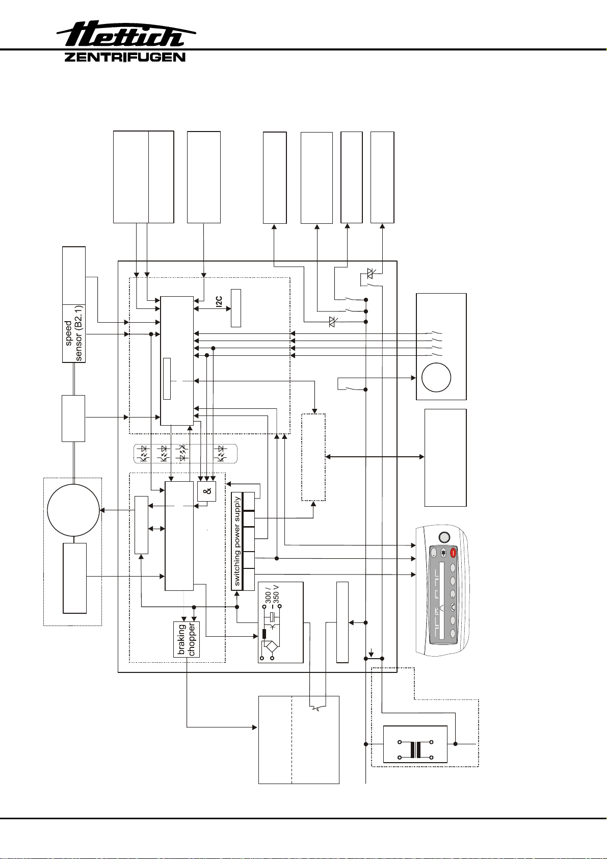
4.1 Block diagram of the control
imbalance
sensor (B2.2)
speed
sensor B4
temperature sensor
S104 S602 S701
(B1) in
1)
centrifuge chamber
S704
1)
switch
overtemperature
Flash-Memory
1)
1)
1)
2)
1)
(B3)
fan (M5)
for cooling
at the condenser
S1001
control
heating (E1)
the motor (M1)
S1000
(M2 / M2.1)
compressor
S900
1) only in centrifuges with cooling
2) only in centrifuges with option
heating/cooling
temperature sensor
S706
fan (M3)
at the condenser
S904
EEPROM
centrifuge-
lid lock
motor-driven
1~
M4
control - processor
3x
S700
RS232
serial interface
RS 232 from / to PC
- programming
- controlling
M 3~
Motor M1
overtemperature
S604 S703S707
START
STOP
12:30450020
9999
OPEN
FC- 3~ driver
S104
switch
drive - processor
frequency converter
(FC)
2.5V 5V
5V
15V 5V
1
line filter
Connection only with
S100
power input 200 - 240 V
S906
S905
power supply
PCF
cutoff
electronics
ROTINA 380 / 380 R
S106
PFC-switching
~
S106
PROG T/°C RCF RPM t/min
electronic operating panel
PROG T/°C RCF RPM TIME
transformer
100 -127 V
(R1)
brake resistor
overtemperature
switch (F3)
at the brake
resistor (R1)
~~
power input 200 - 240 V
power input
120 V 230 V
8/98

These microprocessor controlled centrifuges mainly consist of the following electrical
components:
• Operating panel (A2)
• Electronics ROTINA 380 (A1) resp. Electronics ROTINA 380 R (A1)
• Motor (M1) with 2 speed sensors (B2.1, B4) and an imbalance sensor (B2.2)
• Brake resistor (R1)
• Motor-driven lid lock (A3)
• Cooling system
4.2 Operating panel (A2)
The buttons, the LCD display, the status LEDs and the acoustic beeper are located on
the operating panel.
The operating panel is connected with the Electronics (A1) via a 20-pole flat ribbon
cable.
4.3 Electronics ROTINA 380 (A1) resp. ROTINA 380 R (A1)
There are 2 microprocessors on the Electronics. Both processors (control- and driveprocessor) are communicating internal via a serial interface.
The control-processor carries out the following tasks:
• Reading in the buttons and controlling the LCD display and the LEDs.
• Saving of 99 run programs.
• Evaluating the errors recognized by the frequency converter.
• Voltage supply and evaluation of both speed sensors (B2.1, B4, speedometer).
• Voltage supply and evaluation of the imbalance sensor (B2.2).
• Controlling the motor-driven lid lock.
• Voltage supply 15 V DC and 5 V DC for the operating panel.
• Evaluating the temperature sensors T1, T2 (B1, B3) and controlling the cooling.
• Evaluating the overtemperature switch in the centrifuge chamber.
• Status indication with a yellow LED:
All functions are all right: the yellow LED lights up
The frequency converter carries out the following tasks:
• Generating the motor current supply
(three-phase current with variable frequency and voltage)
Functional description: The supply voltage is rectified, smoothened and
chopped into a pulse width pattern in three bridge
elements with a microprocessor.
• Monitoring the motor current.
• Evaluating the overtemperature switch in the motor (M1).
• The braking chopper transfers the electrical energy produced during braking, from a
voltage of approx. 400 Volt, to the brake resistor in a controlled manner.
9/98

• Status indication with a green LED:
Standby: the green LED lights up
Centrifugation run: the green LED lights up
Case of error: the green LED flashes
If the drive-processor detects an error, it switches off the motor.
4.4 Special features
• Multiprocessor concept:
The control- and the drive-processor monitoring one another. If one processor stops
working, the other processor switches off the drive.
• Interface concept:
The information transmission is monitored with an additional check sum.
• Hardware concept:
All safety related switches are break contacts. This also ensures that loose contacts
and cable rupture can be detected.
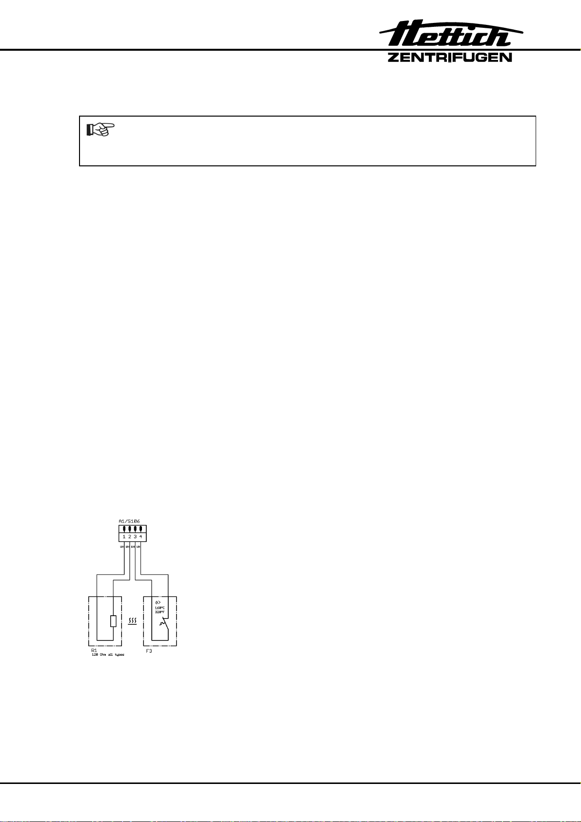
4.5 Brake resistor (R1)
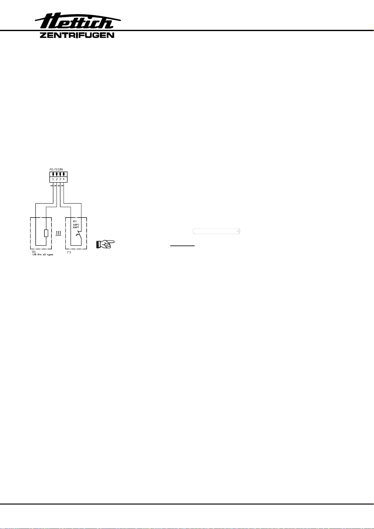
• An overtemperature switch (F3) protects the brake resistor (R1) against fire. If the
braking chopper has a short circuit, the brake resistor becomes hot due to the high
current, and the overtemperature switch (F3) disconnects the supply voltage of the
centrifuge.
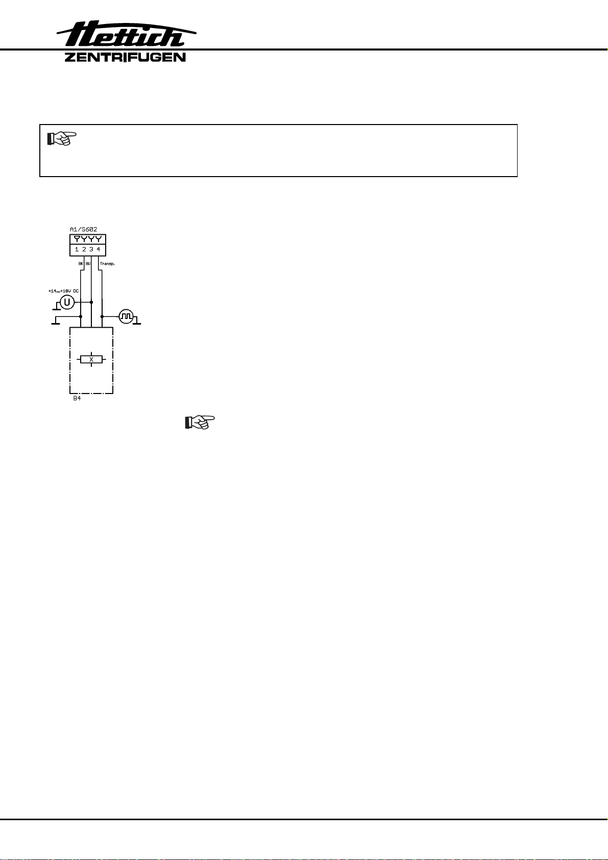
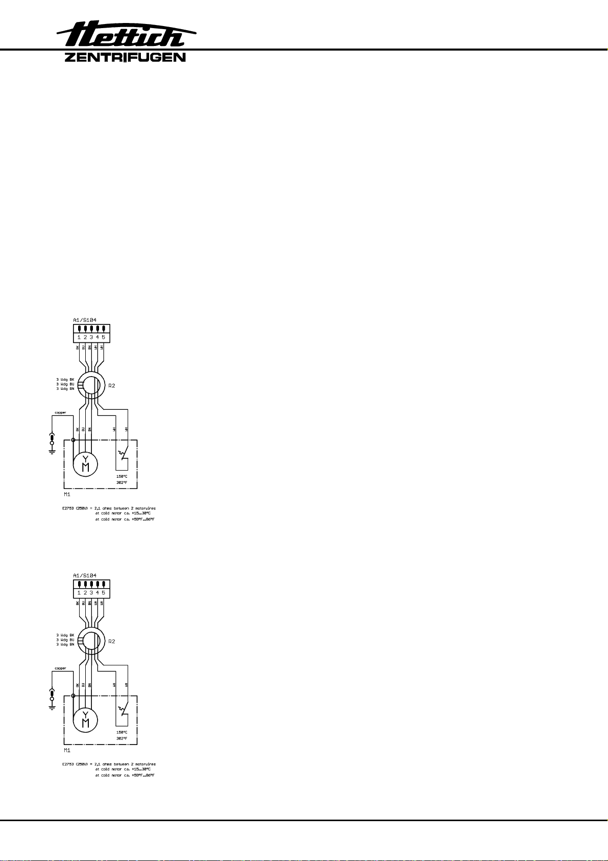
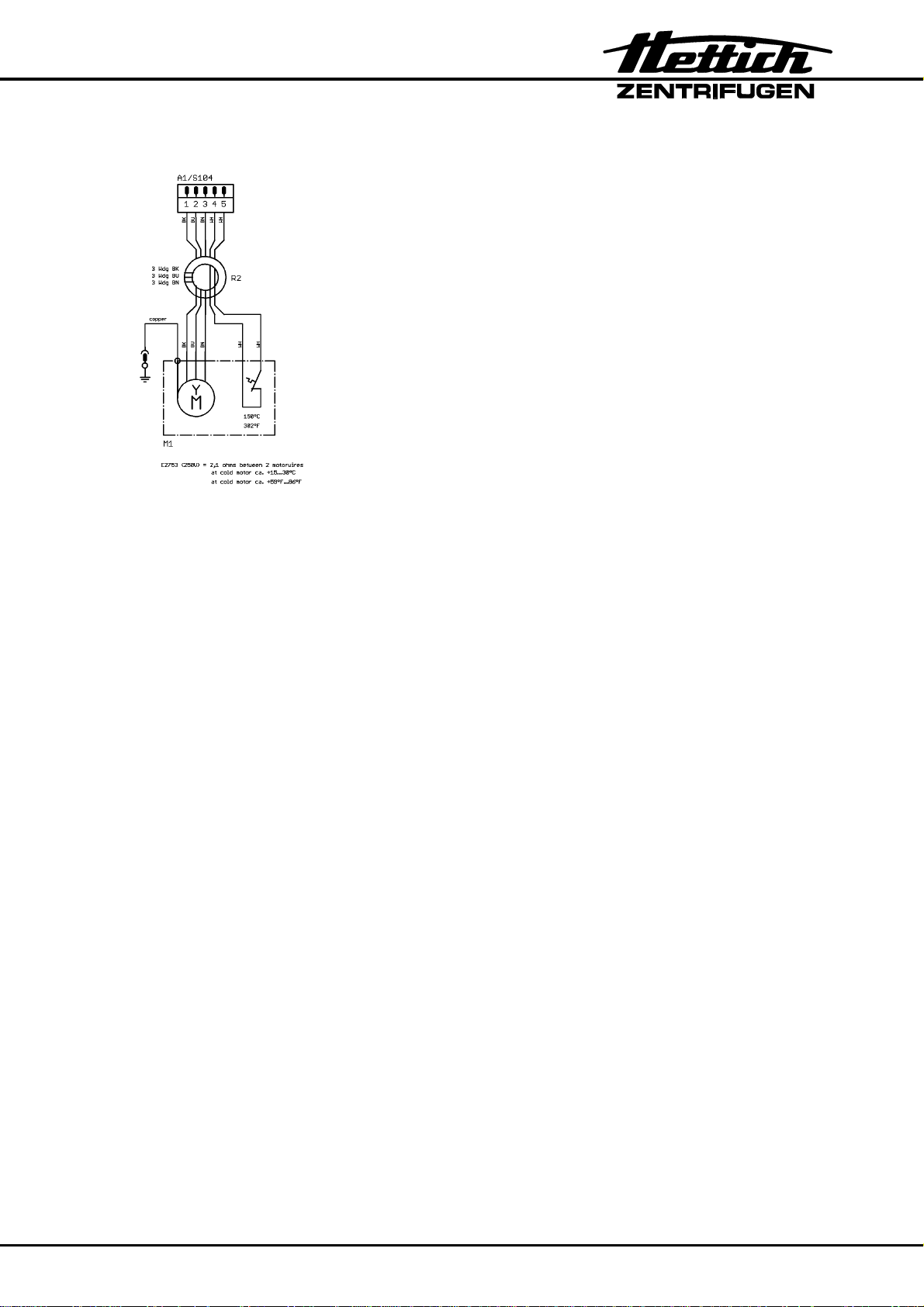
4.6 Motor (M1) / Tacho system (B4, B2.1)
• The motor (M1) is a three-phase asynchronous motor with four pairs of poles.
• A speed sensor (B4, speedometer) which is screwed onto the motor receives
− the rotor code information and
− the speed information (6 pulses per revolution)
from the magnets of the tacho ring attached to the rotor.
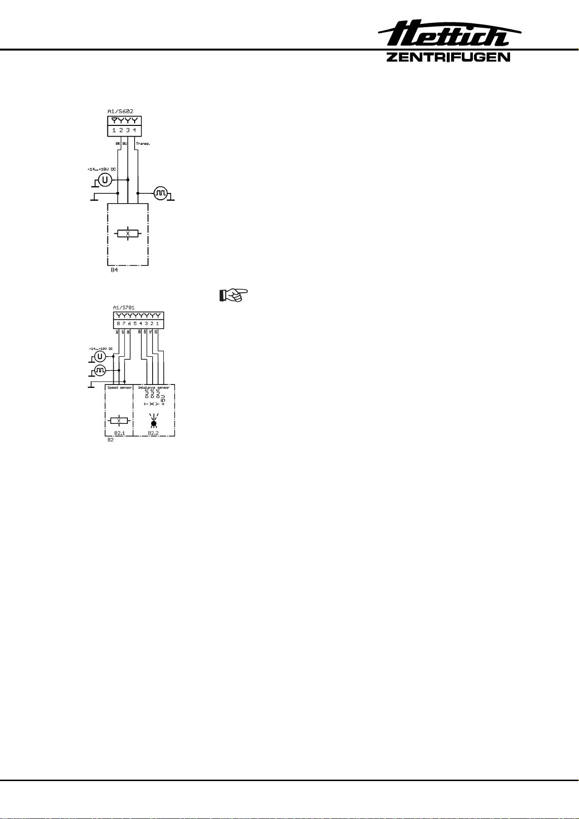
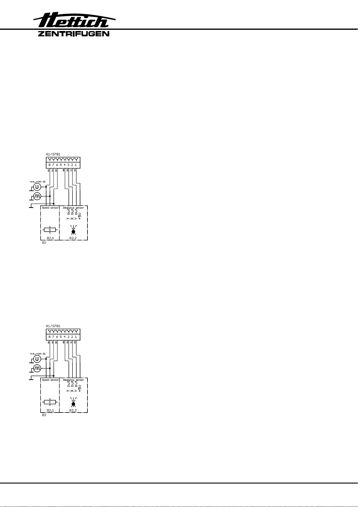
• An additional speed sensor (B2.1, speedometer) is together with the imbalance
sensor (B2.2) in one housing. This housing is screwed to the bottom of the motor.
The speed signal (1 pulse per revolution) will be triggered by a magnet fixed at the
motor axle. This signal is used for the release of the motor-driven lid lock.
• The Electronics (A1) monitors and regulates the speed.
− Double safety:
The drive-processor has been programmed in such a way that it
switches off the drive when the speed is higher than the permissible rotor speed. Then error message "FU/CCI-ERROR 61.19
Overspeed" will be displayed.
• The Electronics (A1) monitors the rotor standstill.
10/98

4.7 Imbalance sensor (B2.2)
• An electronic sensor monitors the imbalance.
• The imbalance sensor (B2.2) and the speed sensor (B2.1) are together in one
housing, screwed to the bottom of the motor (M1).
• Imbalance is detected only in running mode (run up, centrifuging and braking).
• If impermissible imbalance is detected, the drive switches off and the rotor slows
down braked until it stops.
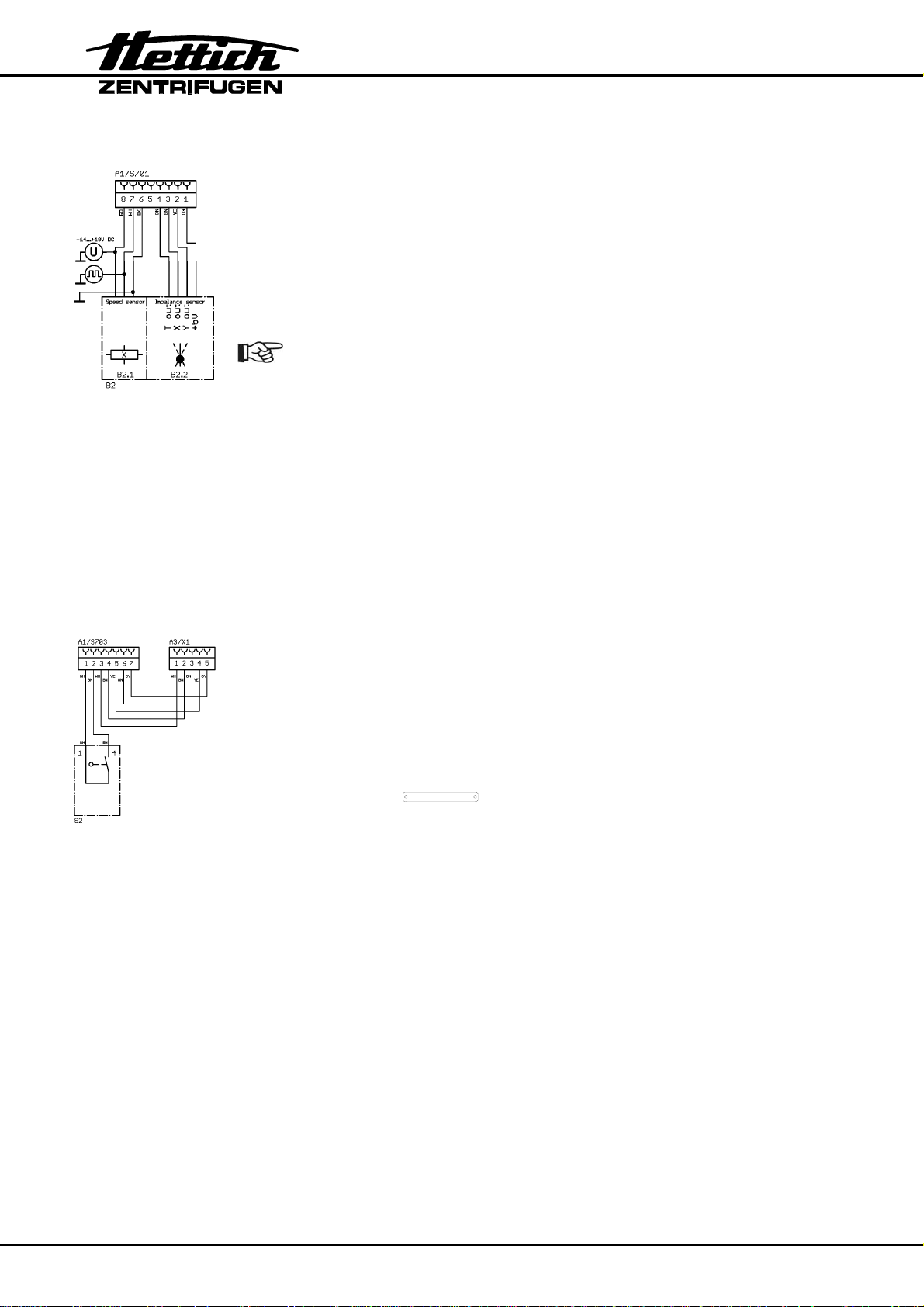
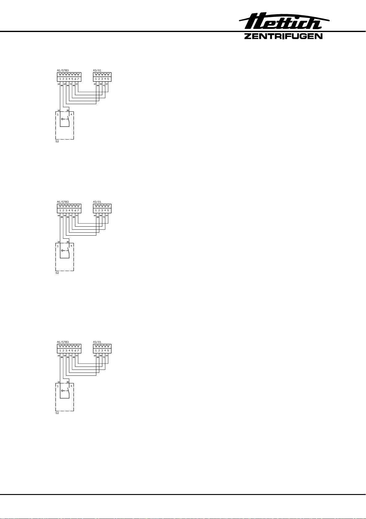
4.8 Motor-driven lid lock (A3)
• The lid can be opened only if the Electronics (A1) has detected rotor standstill.
• By pressing the key
STOP / OPEN
the lid opens motor-driven.
• The motor locks the lid only if both lid brackets actuate both lid switches (Ll, Lr), the
position switch (Mo) for position "lid opened" is actuated and the rotor has standstill.
• The centrifuge can only be started when the lid is closed.
4.9 Cooling system
• The cooling system is a hermetical system.
• The cooling system consists of the following components:
− Compressor (M2, M2.1)
− Cooling tubes around the centrifuge chamber (evaporator)
− Condenser
− Dryer
− Fan (M3)
− Temperature sensor T1 (B1) and overtemperature switch in the centrifuge
chamber
− Temperature sensor T3 (B3) on the condenser
• In the housing of the temperature sensor T1 (B1) also the overtemperature switch is
included. With centrifuges with cooling the drive switches off, when the temperature
is > 60°C / > 140°F, and with option Heating/Cooling > 120°C / > 248°F.
• The refrigerant will be cooled down with a fan (M3). The speed of the fan is
controlled dependent to the temperature at the condenser.
• When opening the lid of the centrifuge, the cooling system switches off.
• When the rotor is at standstill and the lid is closed the centrifuge chamber will be
cooled on the preselected temperature, if this is lower than 20°C / 68°F.
During the standby-cooling the compressor is time-cycle controlled (2 minutes ON /
3 minutes OFF).
11/98

4.10 Safety devices
Mains switch
Over voltage protection and
radio interference suppression
filter
Additional radio interference
suppression filter
Frequency converter
Motor
Centrifuge chamber
5 Troubleshooting procedures
• Fuses in installation in which centrifuge is installed are intact.
• Supply voltage present at (see circuit diagram):
− Connecting cable
− Appliance plug
− Mains switch
− Electronics (A1), plug S100
• Look for the displayed error code in the chapter 6, pg. 13.
• Remedy the error according to the instructions.
• Carry out a functional check after every repair and whenever a component is
replaced, see pg. 76, chapter 9.
with thermal overload protection
⇒
on Electronics (A1)
⇒
in mains input circuit (only with 4706-01)
⇒
on Electronics (A1), electrically protected
⇒
Overtemperature switch (> 150 °C / > 302°F)
⇒
Overtemperature switch (> 60 °C / > 140°F,
⇒
with option Heating/Cooling > 120°C / > 248°F)
12/98

6 Error messages
6.1 Perform a MAINS RESET
• Switch off the mains switch (switch position "0").
• Wait at least 10 seconds and then switch on the mains switch again (switch position
"Ι").
6.2 Brief description
Error designation No. Brief description Page
TACHO-ERROR 1 Speed sensor on top of the motor: Speedometer
pulses break down during rotation
TACHO-ERROR 2 After start command no speedometer pulses
from both speed sensors
IMBALANCE (3)* Imbalance on motor axle 18
CONTROL-ERROR 4.1 Lid lock error 18
CONTROL-ERROR 4.2 Lid lock error 19
CONTROL-ERROR 4.3 Lid lock error 19
CONTROL-ERROR 4.4 Lid lock error 19
CONTROL-ERROR 4.5 Lid lock error 20
N > MAX 5 Excessive speed error 20
CONTROL-ERROR 6 Lid lock error 21
ROTORCODE 10.1 No start code recognized 21
ROTORCODE 10.2 Invalid rotor code 21
ROTORCODE 10.3 Error during reading the rotor code 22
MAINS INTERRUPT (11)* Mains interruption. 22
16
17
VERSION ERROR 12 Incorrect machine type and/or cooling version 22
N < MIN 13 Speed error: slippage is too high 23
CONTROL-ERROR 22 Communication error I2C bus 23
CONTROL-ERROR 25.1 EEPROM read error 23
CONTROL-ERROR 25.2 EEPROM write error 24
CONTROL-ERROR 25.3 EEPROM communication error 24
CONTROL-ERROR 25.4 EEPROM storage error 23
* Error number will not be displayed
13/98

Error designation No. Brief description Page
SER I/O-ERROR 31 TIME OUT, communication error with frequency
converter
SER I/O-ERROR 34 Communication error with frequency converter 24
SER I/O-ERROR 36 NAK, communication error with frequency
converter
°C / *-ERROR 51 Overtemperature on condenser 24
°C / *-ERROR 52 Overtemperature in centrifuge chamber 25
°C / *-ERROR 53 Temperature sensor at the bottom of the
centrifuge chamber is defective
°C / *-ERROR 54 Temperature sensor at the top of the centrifuge
chamber is defective (not existing in ROTINA
380 R)
°C / *-ERROR 55 Temperature sensor on condenser is defective 26
FU/CCI-ERROR 60 Faulty release signal to frequency converter
(drive-processor)
FU/CCI-ERROR 61.1 Undervolt, undervoltage frequency converter 27
FU/CCI-ERROR 61.2 Overvolt, overvoltage frequency converter 27
24
24
25
26
27
FU/CCI-ERROR 61.4 OverT FU, Übertemperatur frequency converter 28
FU/CCI-ERROR 61.5 OverT Mot, overtemperature in motor 28
FU/CCI-ERROR 61.9 OverI Peak, peak current error frequency
converter
FU/CCI-ERROR 61.13 Short cir, short circuit cut-off frequency converter 29
FU/CCI-ERROR 61.16 FU Enable, no enabling for frequency converter 29
FU/CCI-ERROR 61.17 Communication error with control-processor 29
FU/CCI-ERROR 61.18 frequency converter receives wrong direction of
rotation command
FU/CCI-ERROR 61.19 Overspeed, frequency converter recognizes
excess speed
FU/CCI-ERROR 61.20 Faulty speed measurement of the frequency
converter
FU/CCI-ERROR 61.128 Internal frequency converter error 31
FU/CCI-ERROR 61.129 System error of the frequency converter 31
FU/CCI-ERROR 61.130 Program memory of the frequency converter
defective
28
30
30
30
31
FU/CCI-ERROR 61.131 Reset by Watchdog of the frequency converter 31
14/98

Error designation No. Brief description Page
SENSOR-ERROR 90 No mains synchronisation 31
SENSOR-ERROR 91 Imbalance sensor – error (x-axis) 32
SENSOR-ERROR 92 Imbalance sensor – error (y-axis) 32
SENSOR-ERROR 93 Imbalance sensor - error: temperature sensor of
the imbalance sensor defective
TACHO-ERROR 96 Speed sensor at the bottom of the motor:
Speedometer pulses break down during
centrifugation run
°C / *-ERROR 97 Temperature sensor on the Electronics defective 33
°C / *-ERROR 98 Temperature sensor on the Electronics detects
overtemperature
PROGRAMM-
ERROR
MULTI PROG
ERROR
NO ROTOR OR
ROTORCODE
ERROR
N > ROTOR MAX --- Speed in the selected program greater than the
FC INIT ERROR --- Initialisation of the frequency converter is faulty 35
100 Ceck sum error with programs (Single programs) 34
101 Ceck sum error with program linking (Multi
programs)
--- No rotor installed or speed sensor on top of the
motor defective
maximum speed of the rotor (Nmax).
32
33
33
34
34
35
FATAL EEPROM
ERROR 1 – 5
--- EEPROM error 35
15/98
6.3 Description and elimination of errors
After occurrence of a fault the cooling / heating switches off. The standby
cooling takes place after the rotor is at standstill and the lid is closed.
During a fault the lid can be opened after the rotor is at standstill.
TACHO - ERROR 1 wait 3:00
During centrifugation the speedometer pulses of the speed sensor
(B4) on top of the motor are interrupted.
The rotor slows down braked until it stops.
No further user operation possible.
After the rotor is at standstill and the 3 minutes have elapsed the
lid lock will be released and the lid can be opened.
• Reset error code:
− Open the lid.
− Switch off the mains switch (switch position "0").
− Wait at least 10 seconds.
− Turn the rotor vigorously by hand.
− Switch on the mains switch again (switch position "Ι").
• Speed sensor (B4) on top of the motor defective or loose
contact on plug.
Check the function of the speed sensor (B4), see pg. 63,
chapter 7.17, item 6.
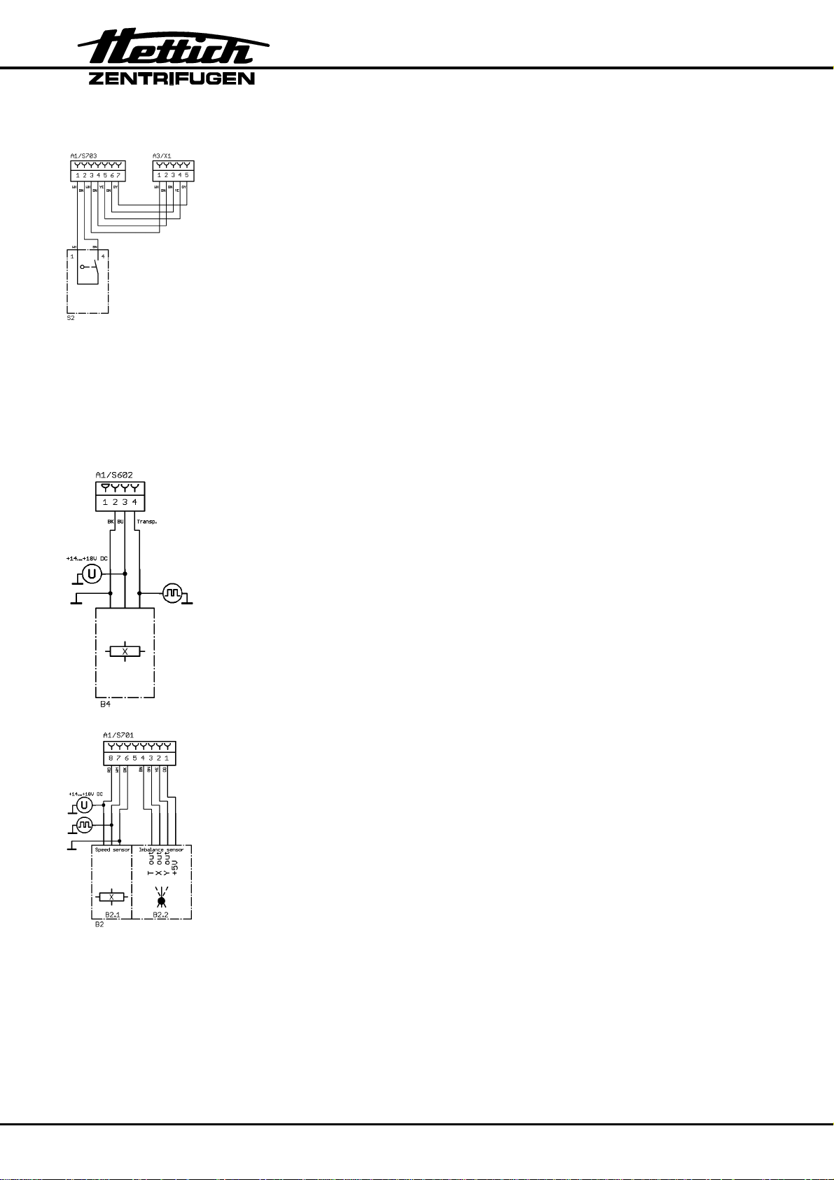
Measure supply voltage on plug S602 / Electronics (A1)
pin 2 – pin 3 (+14-18 VDC).
Measure speedometer pulses on plug S602 / Electronics (A1)
pin 2 - pin 4 (signal).
• Electronics (A1) is defective.
The rotor must turn during switch-on.
16/98
TACHO - ERROR 2 wait 3:00
After start-up no speedometer pulses will be received from both
speed sensors.
The rotor slows down braked until it stops.
No further user operation possible.
After the rotor is at standstill and the 3 minutes have elapsed the lid
lock will be released and the lid can be opened.
• Reset error code:
− Open the lid.
− Switch off the mains switch (switch position "0").
− Wait at least 10 seconds.
− Turn the rotor vigorously by hand.
− Switch on the mains switch again (switch position "Ι").
• Motor is blocked or defective.
• Loose contact on motor plug S104.
• Both speed sensors (B4, B2.1) defective or loose contact on
plug.
− Check the function of the speed sensors, see pg. 63, chapter
7.17, item 6.
The rotor must turn during switch-on.
− Speed sensor (B4) on top of the motor:
Measure supply voltage on plug S602 / Electronics (A1)
pin 2 – pin 3 (+14-18 VDC).
Measure speedometer pulses on plug S602 / Electronics
(A1)
pin 2 - pin 4 (signal).
− Speed sensor (B2.1) at the bottom of the motor:
Measure supply voltage on plug S701 / Electronics (A1)
pin 6 – pin 8 (+14-18 VDC).
Measure speedometer pulses on plug S701 / Electronics
(A1)
pin 6 - pin 7 (signal).
• Electronics (A1) is defective.
17/98
IMBALANCE
Imbalance on motor axle.
The rotor slows down braked until it stops.
• Reset error code:
Open the lid or perform a MAINS RESET.
• Weight difference in rotor components.
• The supporting lugs of the rotor are not lubricated.
• Check grounding of the motor.
• Check the maximum permissible imbalance values, see pg. 60,
chapter 7.15.3.
• Imbalance sensor (B2.2) is defective.
Measure supply voltage on plug S701 / Electronics (A1)
pin 6 – pin 1 (+5 VDC).
Measure on Electronics (A1) / plug S701, pin 6 – pin 2 and
pin 6 – pin 3 (square wave signal 5 V /100 Hz).
• Electronics (A1) is defective.
CONTROL - ERROR 4.1
A missing grounding of the motor causes disturbing signals
which can produce the error.
The lid switches for the left and/or right hook have opened during the
centrifugation run.
The rotor slows down without braking until it stops.
No further user operation possible except opening the lid.
• Reset error code:
After the rotor has stopped perform a MAINS RESET. If the left
LED in the button
on again, press this button so that the motor-driven lid locking
STOP / OPEN
is blinking after turning the centrifuge
once again assumes the normal position (opened).
• An emergency unlocking was performed during the centrifugation
run.
• Switches of the lid lock defective.
Check the function of both switches, see pg. 63, chapter 7.17,
item 21.
Pull out plug S703 and check the function of the switches at the
plug of the cable between pin 1 - pin 2 (left hook) and
pin 3 - pin 4 (right hook).
• Electronics (A1) is defective.
18/98
CONTROL - ERROR 4.2
Error during testing the lid switches after the start command.
No further user operation possible except opening the lid.
• Reset error code:
Perform a MAINS RESET.
• Switches of the lid lock defective.
Check the function of both switches, see pg. 63, chapter 7.17,
item 21.
Pull out plug S703 and check the function of the switches at the
plug of the cable between pin 1 - pin 2 (left hook) and
pin 3 - pin 4 (right hook).
• Electronics (A1) is defective.
CONTROL - ERROR 4.3
Position switch "Mc" of the motor-driven lid lock opens during the
centrifugation run.
The rotor slows down braked until it stops.
No further user operation possible except opening the lid.
• Reset error code:
Perform a MAINS RESET.
• Position switch "Mc" defective.
Check the function of the switch, see pg. 63, chapter 7.17, item
21.
Pull out plug S703 and check the function of the switch at the
plug of the cable between pin 6 - pin 7 (position switch "Mc").
• Electronics (A1) is defective.
CONTROL - ERROR 4.4
The lid can not be locked by motor.
No further user operation possible.
• Reset error code:
Perform a MAINS RESET.
• After opening the lid one of the two lid switches (for the hooks)
remains closed.
• Switches of the lid lock defective.
Check the function of both switches, see pg. 63, chapter 7.17,
item 21.
Pull out plug S703 and check the function of the switches at the
plug of the cable between pin 1 - pin 2 (left hook) and
pin 3 - pin 4 (right hook).
• Electronics (A1) is defective.
19/98
CONTROL - ERROR 4.5
Position switch "Mo" of the motor-driven lid lock closes during the
centrifugation run.
The rotor slows down braked until it stops.
No further user operation possible except opening the lid.
• Reset error code:
Perform a MAINS RESET.
• Position switch "Mo" defective.
Check the function of the switch, see pg. 63, chapter 7.17, item
21.
Pull out plug S703 and check the function of the switch at the
plug of the cable between pin 5 - pin 7 (position switch "Mo").
• Electronics (A1) is defective.
N > MAX 5
Excess speed. The speed measured by the speed sensors B4 or
B2.1 is 250 RPM higher than the maximum speed of the rotor.
The rotor slows down braked until it stops.
No further user operation possible except opening the lid.
• Reset error code:
Perform a MAINS RESET.
• Both speed sensors (B4, B2.1) defective or loose contact on
plug.
− Check the function of the speed sensors, see chapter "7.17,
item 6".
− Speed sensor (B4) on top of the motor:
• Electronics (A1) is defective.
Measure supply voltage on plug S602 / Electronics (A1)
pin 2 – pin 3 (+14-18 VDC).
Measure speedometer pulses on plug S602 / Electronics (A1)
pin 2 - pin 4 (signal).
− Speed sensor (B2.1) at the bottom of the motor:
Measure supply voltage on plug S701 / Electronics (A1)
pin 6 – pin 8 (+14-18 VDC).
Measure speedometer pulses on plug S701 / Electronics (A1)
pin 6 - pin 7 (signal).
20/98
CONTROL - ERROR 6
Lid lock error.
No further user operation possible except opening the lid.
• Reset error code:
• The motor of the lid lock runs too slowly or it is blocked. The
• Position switch "Mc" or "Mo" defective.
• Electronics (A1) is defective.
ROTORCODE 10.1
Start code of the rotor coding not recognized.
Perform a MAINS RESET.
position switch "Mc" or "Mo" must close within 5 seconds.
Check the function of the switch "Mc" or "Mo", see pg. 63,
chapter 7.17, item 21.
Pull out plug S703 and check the function of the switch at the
plug of the cable between pin 6 - pin 7 (position switch "Mc") and
between pin 5 - pin 7 (position switch "Mo").
The rotor slows down braked until it stops.
ROTORCODE 10.2
No further user operation possible except opening the lid.
• Reset error code:
Perform a MAINS RESET.
• Magnetic code on the rotor is defective, see pg. 92, chapter 12.1.
• Electronics (A1) is defective.
An invalid rotor code was read in during start-up.
The rotor slows down braked until it stops.
No further user operation possible except opening the lid.
• Reset error code:
Perform a MAINS RESET.
• Magnetic code on the rotor is defective, see pg. 92, chapter
12.1.
• Motor turns in false direction. Check the motor cables on plug
S104 / Electronics (A1).
• Electronics (A1) is defective.
21/98
ROTORCODE 10.3
Error during reading the rotor code.
The rotor slows down braked until it stops.
No further user operation possible except opening the lid.
• Reset error code:
• Magnetic code on the rotor is defective, see pg. 92, chapter 12.1.
• Electronics (A1) is defective.
MAINS INTERRUPT
Interruption of mains supply during centrifugation.
During the interruption of the mains supply the rotor slows down
without braking until it stops.
After the interruption of the mains supply the rotor slows down
braked until it stops.
• Reset error code:
• Power failure.
• Overtemperature switch (F3) on the brake resistor (R1) has
• Loose contact in the electrical wiring.
• Electronics (A1) is defective.
VERSION ERROR 12
Perform a MAINS RESET.
Open the lid and press the
START / IMPULS
key.
The error code cannot be reset by a MAINS RESET.
opened or is defective.
Incorrect machine type and/or cooling version identified.
No further user operation possible except opening the lid.
• Perform an initialisation of the EEPROM, see chapter "7.20".
Then check the machine type and the cooling version (dispaly
after MAINS RESET).
• The installed electronics (A1) does not fit to the centrifuge model.
• Electronics (A1) is defective.
22/98
N < MIN 13
Insufficient speed, motor slippage is too high.
This error is displayed if the rotor speed (ACTUAL speed) is
longer as 30 seconds lower than the SET speed.
The rotor slows down braked until it stops.
No further user operation possible except opening the lid.
• Reset error code:
• Motor is labouring (damage to bearings).
• Motor has a short-circuited coil (coil is defective).
• Loose contact in the electrical connections.
• Electronics (A1) is defective.
CONTROL - ERROR 22
Communication error I2C bus.
Perform a MAINS RESET.
The rotor slows down braked until it stops.
No further user operation possible except opening the lid.
CONTROL - ERROR 25.1, 25.4
EEPROM: Read or storage error.
The rotor slows down braked until it stops.
• Reset error code:
Perform a MAINS RESET.
• Electronics (A1) is defective.
No further user operation possible except opening the lid.
• Reset error code:
Perform a MAINS RESET.
• Delete the programs and the program linking, see pg. 69, chapter
7.18.
• Initialise the EEPROM, see pg. 71, chapter 7.20.
• Electronics (A1) is defective.
23/98
CONTROL - ERROR 25.2, 25.3
EEPROM: Write or communication error.
The rotor slows down braked until it stops.
No further user operation possible except opening the lid.
SER I/O - ERROR 31, 34, 36
Communication error with the frequency converter.
The rotor slows down without braking until it stops.
°C / * -ERROR 51
• Reset error code:
Perform a MAINS RESET.
• Electronics (A1) is defective.
No further user operation possible except opening the lid.
• Reset error code:
Perform a MAINS RESET.
• Electronics (A1) is defective.
Overtemperature on condenser
The rotor slows down braked until it stops.
No further user operation possible except opening the lid.
• Reset error code:
Perform a MAINS RESET.
• Temperature on condenser ≥ 58°C / 136°F.
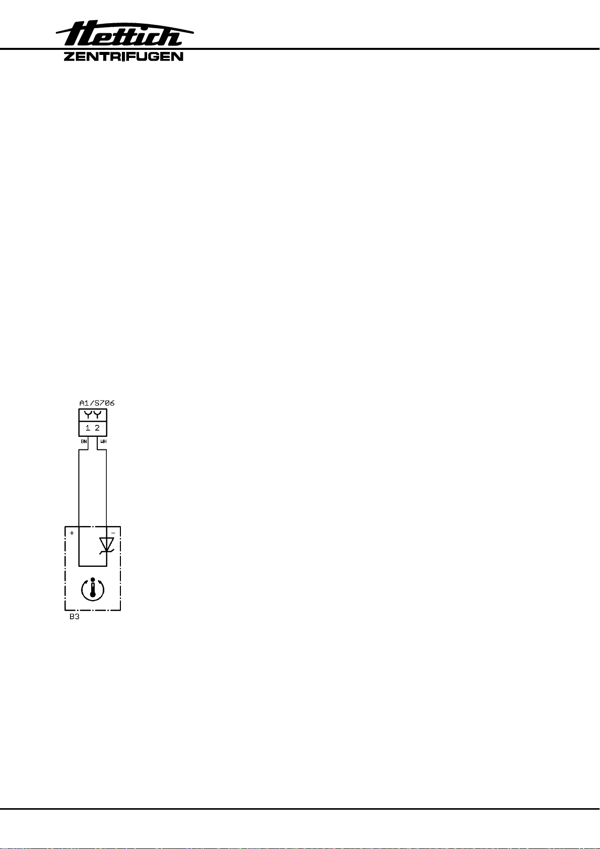
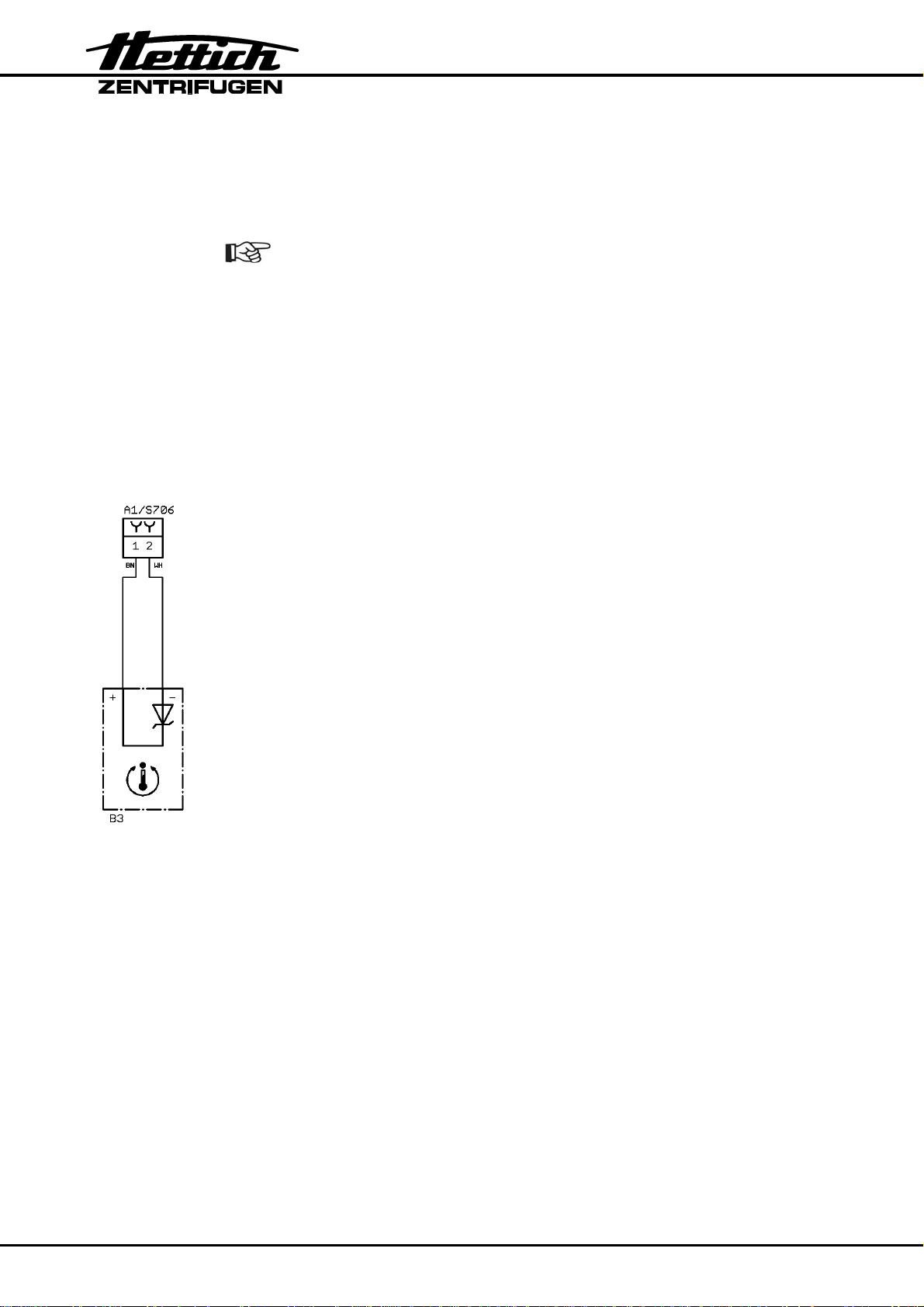
• The temperature sensor (B3) on the condenser is defective.
Measure on Electronics (A1) / plug S706, pin 1 – pin 2.
Voltage > 3.31 V = Temperature on condenser > 58°C / 136°F
Voltage at 25°C / 77°F = 2.98 V (± 20 mV)
A temperature change of 1°K causes a voltage change of 10 mV.
• Electronics (A1) is defective.
• Fan (M3) is defective.
24/98
°C / * -ERROR 52
°C / * -ERROR 53
Overtemperature in centrifuge chamber
The rotor slows down braked until it stops.
No further user operation possible except opening the lid.
• Reset error code:
Perform a MAINS RESET.
• Temperature in centrifuge chamber > 60°C / 140°F, with option
heating/cooling > 120°C / 248°F.
• Overtemperature switch in centrifuge chamber is defective.
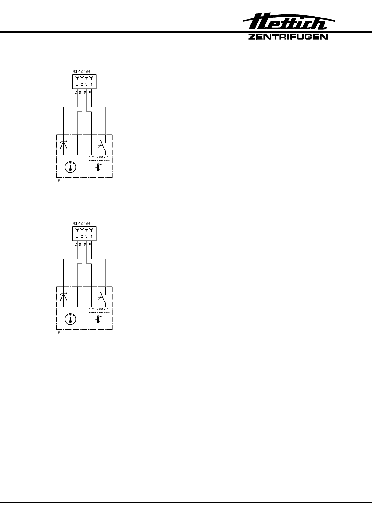
Measure on Electronics (A1) / plug S704, pin 3 – pin 4
Switch closed: 0 VDC
Switch opened: +15 VDC
• Electronics (A1) is defective.
• Cooling is defective.
The temperature in the centrifuge chamber measured by the
temperature sensor (B1) is out of the valid range.
The rotor slows down braked until it stops.
No further user operation possible except opening the lid.
• Reset error code:
Perform a MAINS RESET.
• The temperature sensor (B1) in the centrifuge chamber is
defective.
Measure on Electronics (A1) / plug S704, pin 1 – pin 2.
Valid voltage range: 2,24 V up to 3,92 V.
Voltage < 0.5 V = short circuit
Voltage > 4.5 V = disruption
Voltage at 25°C / 77°F = 2.98 V (± 20 mV)
A temperature change of 1°K causes a voltage change of 10 mV.
• Electronics (A1) is defective.
25/98
°C / * -ERROR 54
The temperature in the centrifuge chamber measured by the
No further user operation possible except opening the lid.
temperature sensor (B2) is out of the valid range. The temperature
sensor (B2) does not exist in the ROTINA 380 R.
If the temperature sensor B2 (= T2) is activated in the "Select
Menu", °C / * -ERROR 54 will be displayed.
°C / * -ERROR 55
• Reset error code:
Perform a MAINS RESET.
• Deactivate the temperature sensor B2 (= T2) in the "Select
Menu", see pg. 55, chapter 7.14.3.
• Electronics (A1) is defective.
The temperature on the condenser measured by the temperature
sensor (B3) is out of the valid range.
The rotor slows down braked until it stops.
No further user operation possible except opening the lid.
• Reset error code:
Perform a MAINS RESET.
• The temperature sensor (B3) on the condenser is defective.
Measure on Electronics (A1) / plug S706, pin 1 – pin 2.
Valid voltage range: 2,24 V up to 3,92 V.
Voltage < 0.5 V = short circuit
Voltage > 4.5 V = disruption
Voltage at 25°C / 77°F = 2.98 V (±20 mV)
A temperature change of 1°K causes a voltage change of 10 mV.
• Electronics (A1) is defective.
26/98
General notes for FU/CCI-ERROR 60 to FU/CCI-ERROR 61.131
If the drive-processor detects an error, it switches off the motor.
After occurrence of a fault the green LED on the electronics (A1) flashes
quickly.
FU/CCI-ERROR 60
Error when checking the enable signal to frequency converter (drive-
processor).
No further user operation possible except opening the lid.
FU/CCI-ERROR 61.1 Undervolt
• Reset error code:
Perform a MAINS RESET.
• Electronics (A1) is defective.
Frequency converter error. Undervoltage in the intermediate circuit.
The rotor slows down without braking until it stops.
No further user operation possible except opening the lid.
FU/CCI-ERROR 61.2 Overvolt
• Reset error code:
Perform a MAINS RESET.
• Mains voltage is too low. Admissible mains voltage see pg. 98,
chapter 12.4.
• Electronics (A1) is defective.
Frequency converter error. Overvoltage.
The voltage in intermediate circuit is > 426 V DC.
This error normally only occurs when the drive is being braked.
The rotor slows down without braking until it stops.
No further user operation possible except opening the lid.
• Reset error code:
Perform a MAINS RESET.
• Check the electrical wiring and the plug S106 of the brake
resistor (R1).
• Brake resistor (R1) is defective.
• Electronics (A1) is defective.
27/98
FU/CCI-ERROR 61.4 OverT FU
Overtemperature in the frequency converter.
Temperature ≥ 78°C / 172°F.
The rotor slows down without braking until it stops.
No further user operation possible except opening the lid.
• Reset error code:
Perform a MAINS RESET.
• The thermal conduction from the frequency converter to the
supporting sheet of the electronics (A1) is not sufficient.
• Full load operation at an ambient temperature > 35°C / 95°F.
• Electronics (A1) is defective.
FU/CCI-ERROR 61.5 OverT Mot
Overtemperature in the motor. Temperature > 150°C / 302°F.
The rotor slows down without braking until it stops.
No further user operation possible except opening the lid.
• Reset error code:
Perform a MAINS RESET.
• Overtemperature switch opens because of overtemperature in
the motor.
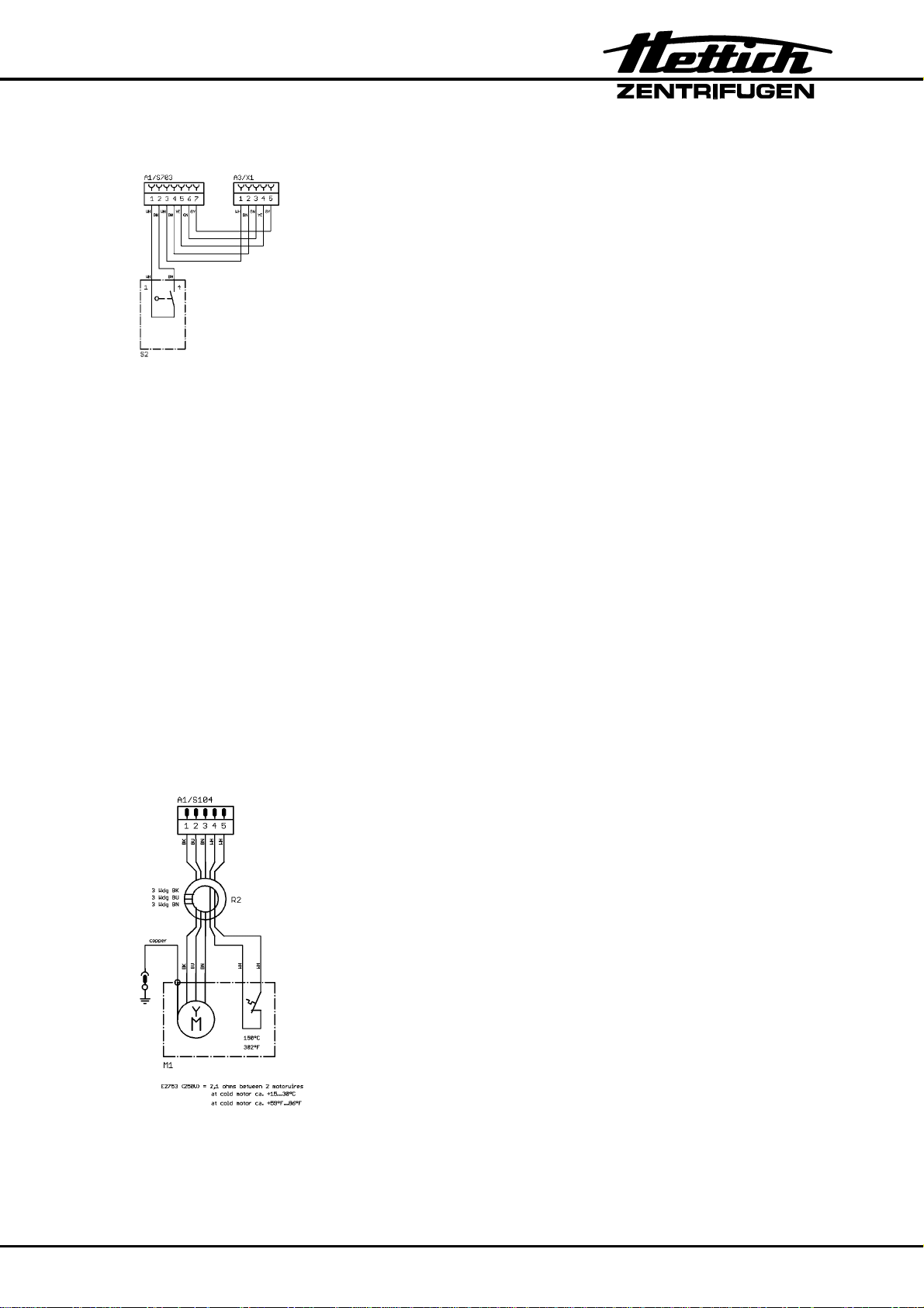
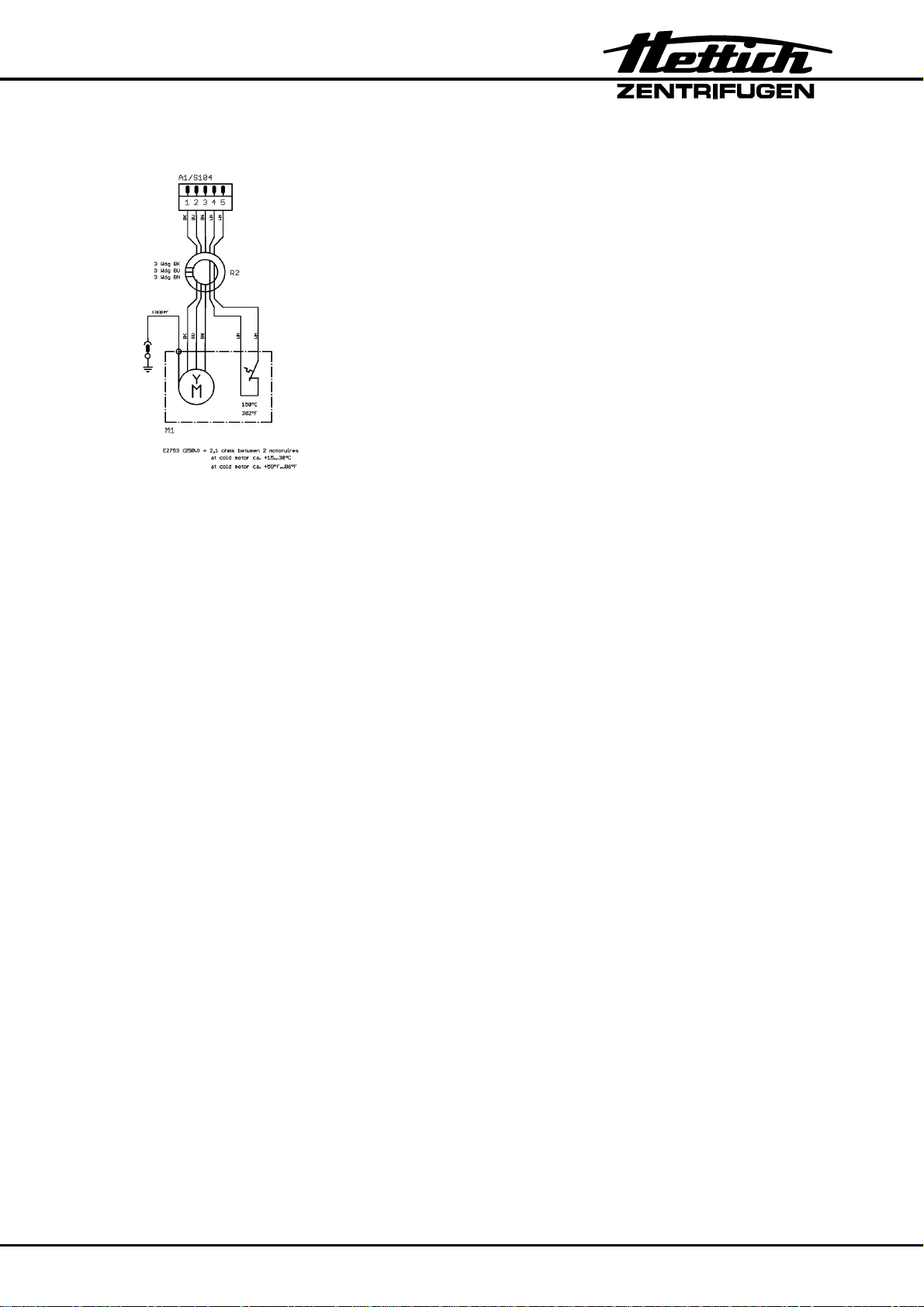
Remove plug S104 and measure at the plug between pin 4 pin 5:
Switch closed: ≈ 0 Ω
Switch opened: ∞ Ω
• Electronics (A1) is defective.
• Motor is defective.
FU/CCI-ERROR 61.9 Overl Peak
28/98
Overcurrent in the frequency converter (peak current).
The rotor slows down without braking until it stops.
No further user operation possible except opening the lid.
• Reset error code:
Perform a MAINS RESET.
• Short circuit in the motor.
Remove plug S104 and check at the plug pin 1, pin 2, pin 3
the resistance of the motor coils.
• Electronics (A1) is defective.
FU/CCI-ERROR 61.13 Short cir
Short circuit switch-off of the frequency converter.
The rotor slows down without braking until it stops.
No further user operation possible except opening the lid.
• Reset error code:
Perform a MAINS RESET.
• Short circuit in the motor.
Remove plug S104 and check at the plug pin 1, pin 2, pin 3
the resistance of the motor coils.
• Electronics (A1) is defective.
FU/CCI-ERROR 61.16 FU Enable
No enabling for frequency converter.
The rotor slows down without braking until it stops.
No further user operation possible.
FU/CCI-ERROR 61.17
Communication error with control-processor.
The rotor slows down without braking until it stops.
• Reset error code:
• Switches of the lid lock defective.
• Electronics (A1) is defective.
No further user operation possible.
• Reset error code:
• Electronics (A1) is defective.
Perform a MAINS RESET.
Check the function of both switches, see chapter "7.17, item 21".
Pull out plug S703 and check the function of the switches at the
plug of the cable between pin 1 - pin 2 (left hook) and
pin 3 - pin 4 (right hook).
Perform a MAINS RESET.
29/98
FU/CCI-ERROR 61.18
Frequency converter receives wrong direction of rotation command.
The rotor slows down without braking until it stops.
No further user operation possible.
FU/CCI-ERROR 61.19 Overspeed
FU/CCI-ERROR 61.20
• Reset error code:
Perform a MAINS RESET.
• Electronics (A1) is defective.
The frequency converter recognises excess speed. It evaluates the
signals from the speed sensor (B2.1) at the bottom of the motor.
The error occurs, if the speed measured by the speed sensor
(B2.1) is longer as 0.5 seconds 250 RPM higher than the maximum
speed of the rotor (Nmax).
The rotor slows down without braking until it stops.
No further user operation possible.
• Reset error code:
Perform a MAINS RESET.
• Speed sensor (B2.1) at the bottom of the motor defective or
loose contact on plug.
Measure supply voltage on plug S701 / Electronics (A1)
pin 6 – pin 8 (+14-18 VDC).
Measure speedometer pulses on plug S701 / Electronics (A1)
pin 6 - pin 7 (signal).
• Electronics (A1) is defective.
30/98
Faulty speed measurement of the frequency converter.
The rotor slows down without braking until it stops.
No further user operation possible.
• Reset error code:
Perform a MAINS RESET.
• Speed sensor (B2.1) at the bottom of the motor defective or
loose contact on plug.
Measure supply voltage on plug S701 / Electronics (A1)
pin 6 – pin 8 (+14-18 VDC).
Measure speedometer pulses on plug S701 / Electronics (A1)
pin 6 - pin 7 (signal).
• Electronics (A1) is defective.
 Loading...