

Page 1

INDOOR COOKING
Microwave Built-In Kit
AKMWCK
Installation Manual
Page 2
IF THE INFORMATION IN THIS MANUAL IS NOT FOLLOWED
EXACTLY, A FIRE OR EXPLOSION MAY RESULT CAUSING
PROPERTY DAMAGE, PERSONAL INJURY, OR DEATH.
Do not store or use gasoline or other flammable vapors and liquids in the vicinity of this or
any other appliance.
Installation and service must be performed by a qualified installer or service agency.
DO NOT REPAIR, REPLACE OR REMOVE ANY PART OF THE APPLIANCE UNLESS
SPECIFICALLY RECOMMENDED IN THE MANUAL. IMPROPER INSTALLATION,
SERVICE OR MAINTENANCE CAN CAUSE INJURY OR PROPERTY DAMAGE. REFER
TO THIS MANUAL FOR GUIDANCE. ALL OTHER SERVICING SHOULD BE DONE BY
A HESTAN AUTHORIZED SERVICE TECHNICIAN.
READ THESE INSTRUCTIONS CAREFULLY AND COMPLETELY BEFORE
INSTALLING OR USING YOUR APPLIANCE TO REDUCE THE RISK OF
FIRE, BURN HAZARD, OR OTHER INJURY. KEEP THIS MANUAL FOR
FUTURE REFERENCE.
SAFETY DEFINITIONS
THIS INDICATES THAT DEATH OR SERIOUS INJURY MAY OCCUR AS A
RESULT OF NOT OBSERVING THIS WARNING
THIS INDICATES THAT MINOR OR MODERATE INJURY MAY OCCUR AS
A RESULT OF NOT OBSERVING THIS WARNING.
THIS INDICATES THAT DAMAGE TO THE APPLIANCE OR PROPERTY
MAY OCCUR AS A RESULT OF NOT OBSERVING THIS WARNING.
INSTALLER: LEAVE THIS MANUAL WITH THE OWNER OF THE APPLIANCE.
HOMEOWNER: RETAIN THIS MANUAL FOR FUTURE REFERENCE.
Page 3
CONTENTS
1 SAFETY PRECAUTIONS - BEFORE YOU BEGIN
2 INSTALLATION INSTRUCTIONS
2 APPLICATION AND PURPOSE
3 STEP 1 - CABINET OR WALL OPENING
3 STEP 2 - EXHAUST DUCT ASSEMBLY
5 STEP 3 - SURFACE INSTALLATION
SAFETY PRECAUTIONS - BEFORE YOU BEGIN
When properly cared for, your Hestan appliance will provide safe, reliable service for many years. When using
this appliance, basic safety practices must be followed as outlined below.
IMPORTANT: Save these instructions for the local Gas or Utility Inspector’s use.
INSTALLER: Please leave this Installation Manual with the owner.
OWNER: Please retain this Installation Manual for future reference.
Do NOT install this appliance outdoors.
EN
ELECTRICAL SHOCK HAZARD
Disconnect power before installing or servicing appliance. Failure to do so can result
in electrical shock or death. It is the responsibility of the user to have the appliance
connected by a licensed electrician in accordance with all applicable codes and
standards, including fire-related construction, or in the absence of local codes, in
accordance with the National Electrical Code.
ELECTRICAL GROUNDING
• This appliance must be grounded. Grounding reduces the risk of electric shock
in the event of a short circuit. Read the ELECTRICAL SUPPLY section of the
appliance installation manual for complete instructions.
• This appliance is equipped with a 3-prong grounding plug for your protection against shock hazard and
should be directly plugged into a properly grounded receptacle. Do not cut or remove the grounding
prong from this plug.
ELECTRICAL SUPPLY
The appliance must be on its own dedicated circuit - 120 VAC, Single Phase, 60 Hz, with a current rating of 15
Amps. Have the installer show you where the electric circuit breaker is located so you know how to shut off
the power to this appliance.
©2019 Hestan Commercial Corporation
1
Page 4
INSTALLATION INSTRUCTIONS
APPLICATION AND PURPOSE
EN
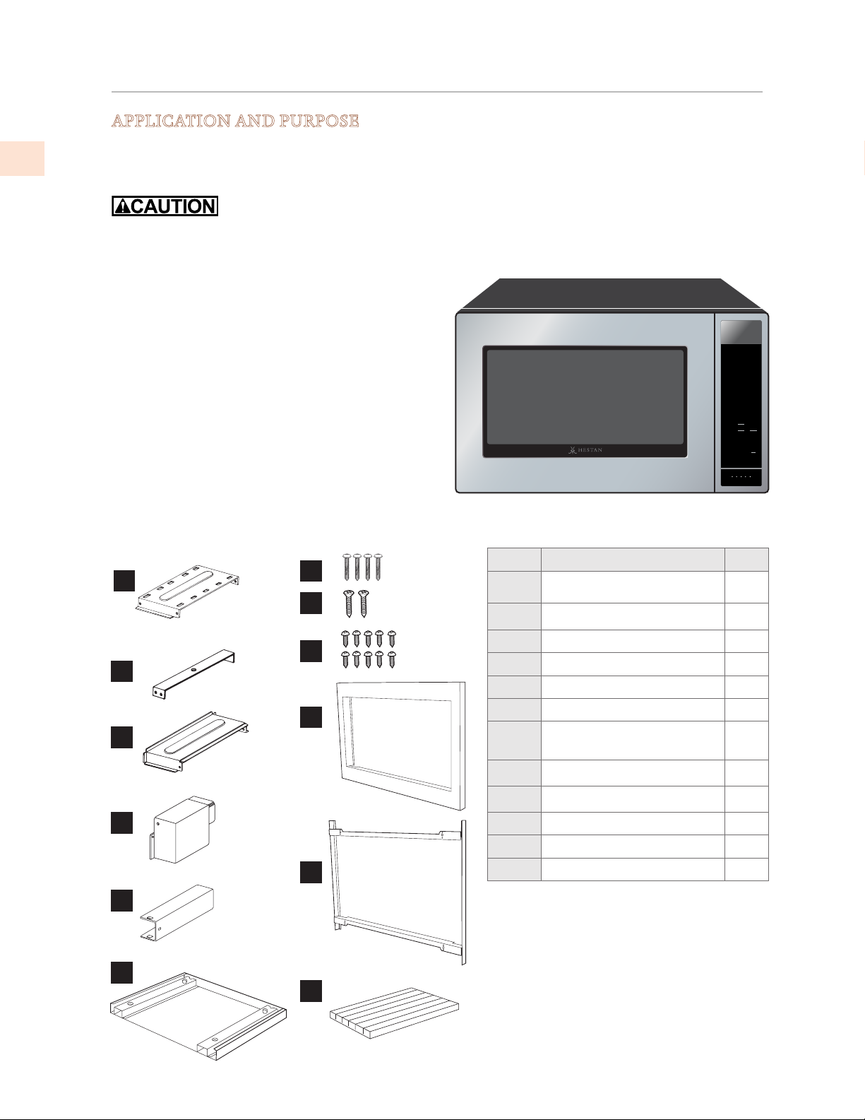
The AKMWCK27 and AKMWCK30 Built-In Kit kits are UL approved to allow certain microwave ovens
to be installed above any electric wall oven. Please see the operation manual regarding approved built-in
applications.
This Built-in Kit is designed for and approved only for those HESTAN Microwave Ovens specifying Built-In
Kit AKMWCK27 or AKMWCK30, such as KMWC24.
Refer to the Convection Microwave Use and Care
Manual or www.hestanhome.com.
PLEASE READ THESE INSTRUCTIONS
THOROUGHLY BEFORE BEGINNING
INSTALLATION!
SENSOR
REHEAT
Always DISCONNECT THE PLUG of the microwave
oven from the electrical outlet before installing the
Built-in Kit. Remove the turntable from the oven
cavity.
Because the kit includes metal parts, due caution
should be used in handling and installation to avoid the
POPCORN
SENSOR
1 BAKED POTATOES
2 FROZEN VEGETABLES
3 FRESH VEGETABLES-SOFT
4 FRESH VEGETABLES-HARD
5 FROZEN ENTREES
6 HOT DOGS
7 BACON
8 FISH, SEAFOOD
CONVECTION
1 HAMBURGERS
2 CHICKEN PIECES
3 STEAKS
4 FISH STEAKS
1 CHICKEN
2 TURKEY
3 TURKEY BREAST
4 PORK
1 BUNDT CAKE
2 COOKIES
3 MUFFINS
4 FRENCH FRIES
PREHEAT BROIL
SLOW
COOK
2 3
1
150ºF 275ºF
100ºF
6
7
350ºF
375ºF
KITCHEN
TIMER
POWER
LEVEL
possibility of injury.
HELP
MENU
EXTRA
MINUTE
DEFROST
SENSOR
COOK
AUTO
BROIL
AUTO
ROAST
AUTO
BAKE
CONV.
BAKE
LOW MIX
HIGH MIX
BAKE
ROAST
5
4
325ºF
300ºF
0
9
8
450ºF
425ºF
400ºF
STOP
CLOCK
CLEAR
START
B
C
D
E
F
A
DUCT (A)-1
DUCT (A)-2
DUCT (A)-3
DUCT (B)
DUCT (C)
G
H
K
ITEM PART NAME QTY
A
DUCT (A)-1
B
DUCT (A)-2
C
I
J
DUCT (A)-3
D
DUCT (B)
E
DUCT (C)
F
BOTTOM DUCT ASSEMBLY
M3.9-16MM PAN HEAD
G
TAPPING SCREW, ZINC
H
WOOD SCREW
I
CABINET SCREW/ CLEAR
J
FRONT FRAME
K
BACK FRAME
L
CUSHION SHEET
1
1
1
1
1
1
4
2
10
1
1
1
Check list for parts when unpacking.
Note: Front Frame (J) and Back Frame (K) are
shipped attached. Snap apart before installation.
L
2
©2019 Hestan Commercial Corporation
Page 5
INSTALLATION INSTRUCTIONS
STEP 1 CABINET OR WALL OPENING
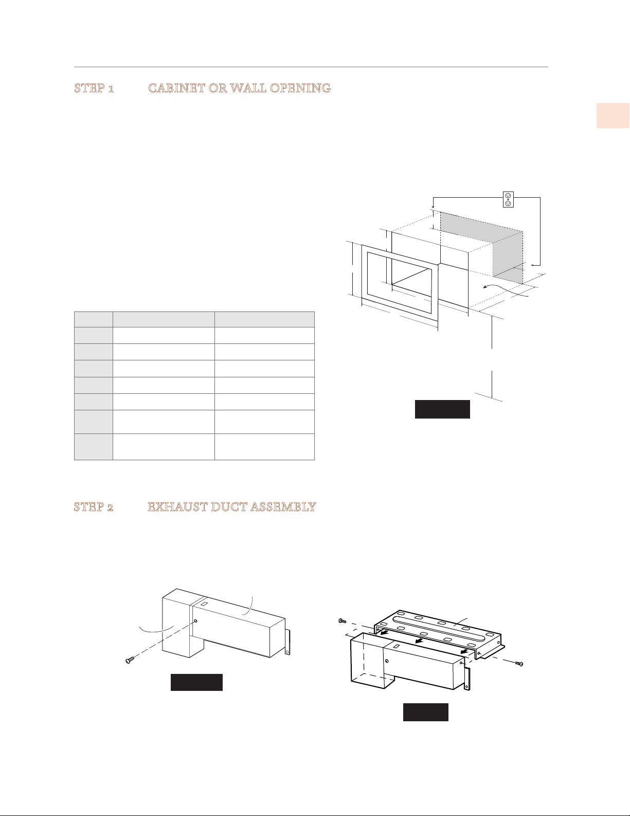
Provide an opening in the wall or cabinet as indicated
in Figure 1. The depth should be a minimum of 20-1/8"
[51.1 cm]. If the Depth (E) dimension is greater than
21" [53.3 cm], the outlet location may be in any area
on the rear wall. The floor of the opening should be
constructed of plywood strong enough to support the
weight of the oven - approximately 100 lbs. [45kg], and
should be level for proper operation of the oven.
NOTE: While the proper function of the oven does
not require that the opening be enclosed (with sides,
ceiling and rear partition), this may be required by local
code, and it is suggested that the local code be checked
for any such requirement.
The opening in the wall or cabinet must be within
the following dimensions, centered horizontal to the
cabinet.
AKMWCK27 AKMWCK30
A
B
C
D
E
F
20" [50.8 cm] 20" [50.8 cm]
26-7/8" [68.3 cm] 29-7/8" [75.9 cm]
18-1/2" [47 cm] 18-1/2" [47 cm]
25-1/4" [64.1 cm] 25-1/4" [64.1 cm]
Min. 20-1/8" [51.1 cm] Min. 20-1/8" [51.1 cm]
5" [12.7 cm] 5" [12.7 cm]
(CONT.)
Outlet should NOT be in the shaded area as
indicated on Figure 1.
NOTE: If the dimension of DEPTH (E) is more
than 21" [53.3 cm], the outlet location may be any
area on the rear wall.
F
C
A
D
B
NOTE: Floor of opening
should be 90˚ to front
cabinet frame.
34-1/2”
[87.6 cm] MIN.
FLOOR
Figure 1
G
FLOOR
E
EN
G
10" [25.4 cm] 10" [25.4 cm]
STEP 2 EXHAUST DUCT ASSEMBLY
A. Insert the edge of DUCT (B) into the hold lip of
DUCT (C). Secure together by using a SCREW (I)
provided in the kit. See Figure 2.
DUCT (C)
DUCT (B)
SCREW (1)
Figure 2
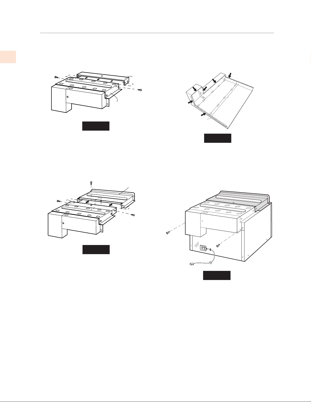
B. Position DUCT (A)-1 on the top of the oven
inserting edge of DUCT (BC) assembly into hole
lip of DUCT (A)-1. Tighten two SCREWS (I),
securing DUCT (A)-1 to DUCT (BC) assembly.
See Figure 3.
SCREW (I)
DUCT (BC)
Figure 3
DUCT (A)-1
SCREW (I)
©2019 Hestan Commercial Corporation
3
Page 6
INSTALLATION INSTRUCTIONS
(CONT.)
EN
C. Position DUCT (A)-2 on the top of the oven and
insert it into the hold lip of DUCT (A)-1. Secure
DUCT (A)-2 to DUCT (A)-1 using two SCREWS
(I) provided. See Figure 4.
SCREW (I)
DUCT (A)-1
Figure 4
DUCT (A)-2
SCREW (I)
D. Position DUCT (A)-3 on top of the oven and
insert it into DUCT (A)-2. Secure DUCT (A)-3
using three SCREWS (I) provided. See Figure 5.
SCREW (I)
DUCT (A)-3
E. Carefully turn over exhaust assembly. Remove
adhesive backing from CUSHION L. The cushion
should be applied to the flanges of the duct
assembly as indicated by arrows. See Figure 6.
CUSHION (L)
Figure 6
F. Remove SCREW from the upper right and left
corners at the rear of the oven. Place duct
assembly on the top of the unit as shown and
secure the duct assembly to the oven using the
two screws just removed from the oven. See
Figure 7.
SCREW (I)
Figure 5
SCREW (I)
DUCT (A)-2
SCREW
SCREW
Figure 7
4
©2019 Hestan Commercial Corporation
Page 7
INSTALLATION INSTRUCTIONS
STEP 3 SURFACE INSTALLATION
(CONT.)
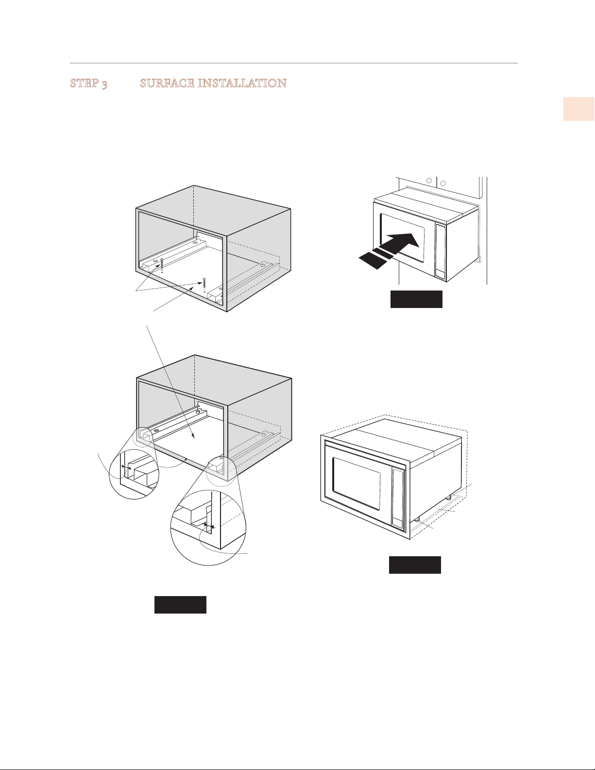
A. BOTTOM DUCT ASSEMBLY: Place the Bottom
duct in the center of the opening so that gap
"A" is equal to gap "B". When the Bottom Duct
assembly is positioned properly, the front edge
of the duct will be flush with the front of the
cabinet. Secure with 2 SCREWS (H). See Figure 8.
SCREW (H)
BOTTOM
DUCT ASSEMBLY
B. CABINET INSTALLATION: Place the oven
adjacent to the wall or cabinet opening. Plug the
power cord into the electrical outlet. Carefully
guide the assembled oven into the prepared
opening. Slide the oven on the Bottom Duct
assembly. See Figure 9.
Figure 9
C. CABINET INSTALLATION: Avoid pinching the
cord between the oven and the wall. Adjust the
position of the oven so that the feet of the oven
are fitted into the holes of the Bottom Duct
Assembly. See Figure 10.
EN
GAP "A"
DETAIL A
NOTE:
Center Bottom Duct
Assembly in the opening
so that gaps A, B are equal.
Figure 8
DETAIL B
GAP "B"
FOOT
BOTTOM DUCT
ASSEMBLY
DUCT RECESS
Figure 10
©2019 Hestan Commercial Corporation
5
Page 8
INSTALLATION INSTRUCTIONS
(CONT.)
EN
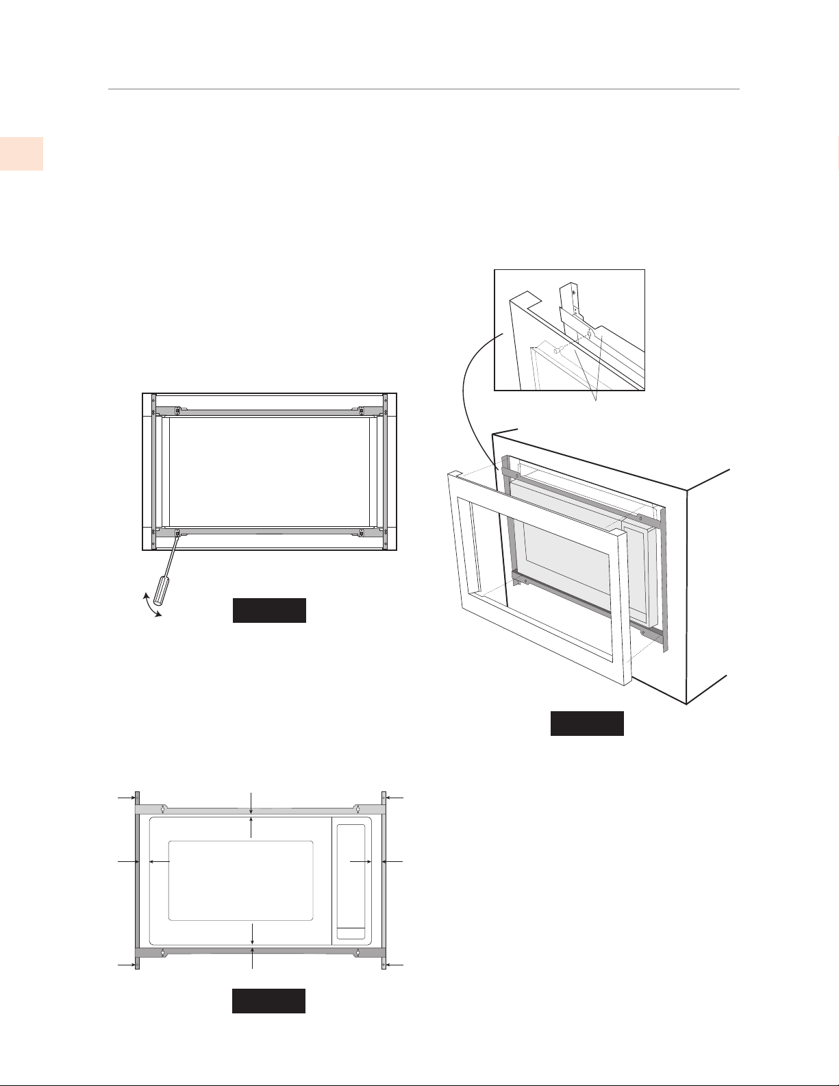
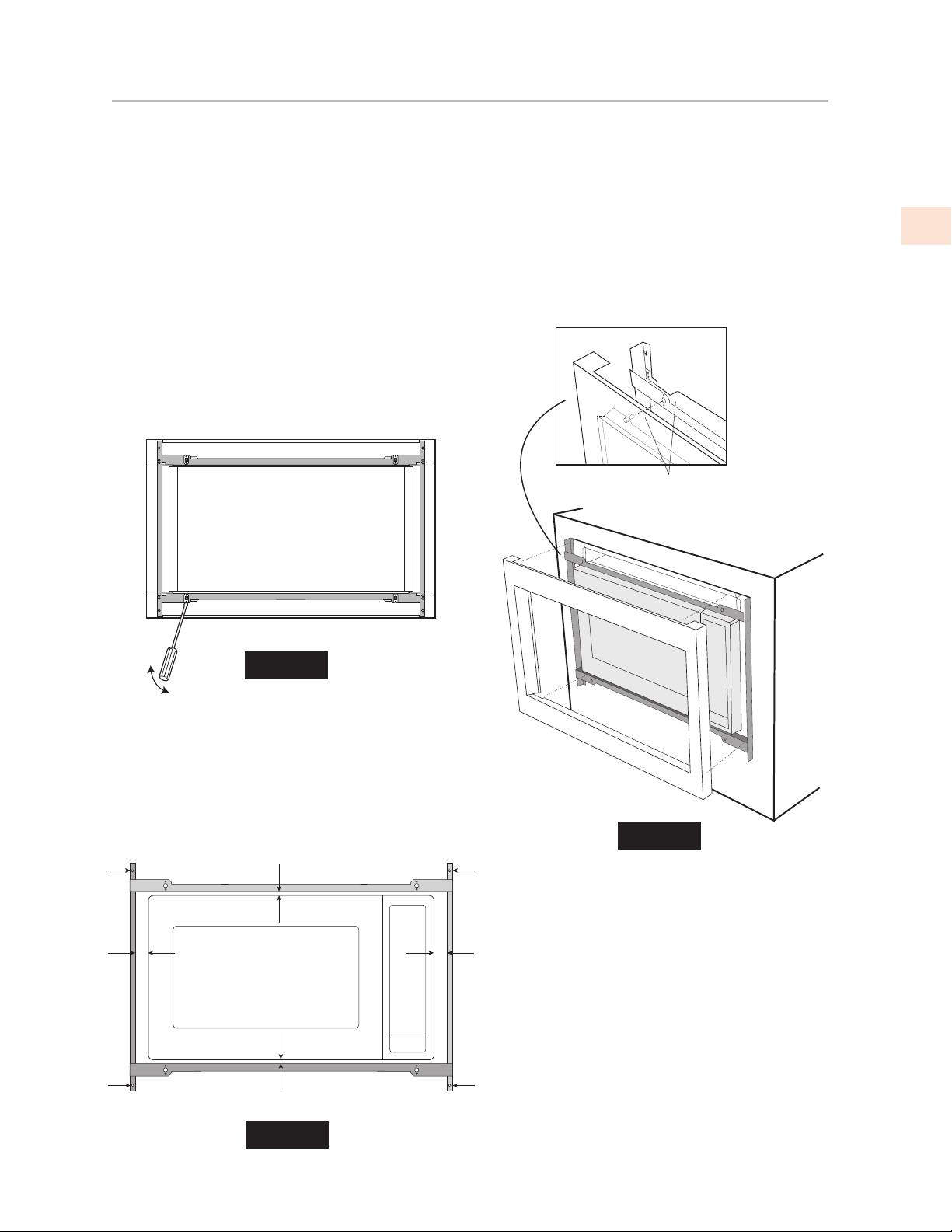
D. DISASSEMBLY: The FRONT FRAME (J) and
BACK FRAME (K) come pre-assembled with ball
studs engaged in the receivers.
• To Separate the FRONT FRAME from the BACK
FRAME:
a) Place the assembly face down on a
protected surface.
b) At the location of the ball stud, insert
a flat head screwdriver between the
FRONT FRAME and the BACK FRAME
and gently pry up to disengage the ball
stud from the receiver.
c) Repeat for each corner. See Figure 11.
F. FRONT FRAME INSTALLATION:
a) Place the FRONT FRAME (J) onto the BACK
FRAME (K) and align ball studs and receivers.
b) Secure the FRONT FRAME to the BACK
FRAME by firmly pushing the front frame
onto the back frame engaging the four (4)
snap attachments. See Figure 13.
SNAP
ATTACHMENT
Figure 11
E. BACK FRAME INSTALLATION: Position back
frame equal space top to bottom, side to side.
Mark for 4holes, center punch and pre-drill with
1/16" [1.45 mm] drill bit. Secure frame with 4
SCREWS (G). See Figure 12.
MOUNTING HOLES
EQUAL GAP
SIDE TO SIDE
MOUNTING HOLES
EQUAL GAP TOP, BOTTOM
Figure 12
MOUNTING HOLES
MOUNTING HOLES
Figure 13
6
©2019 Hestan Commercial Corporation
Page 9
LE NON-RESPECT À LA LETTRE DE CES INSTRUCTIONS PEUT CAUSER
UN INCENDIE OU UNE EXPLOSION, QUI POURRAIT ENTRAÎNER DES
DOMMAGES MATÉRIELS, DES BLESSURES OU LA MORT.
Ne pas entreposer ou utiliser d’essence ou tout autre liquide ou gaz inflammable à
proximité de cet appareil ou de tout autre appareil.
L’installation et le service doivent être effectués par un installateur qualifié ou une agence
de service.
NE PAS RÉPARER, REMPLACER OU ENLEVER TOUTE PIÈCE DE L’APPAREIL, SAUF
SI SPÉCIFIQUEMENT RECOMMANDÉ DANS LES MANUEL. UNE INSTALLATION,
UN ENTRETIEN OU UNE MAINTENANCE INCORRECTS PEUT ENTRAÎNER DES
BLESSURES OU DES DOMMAGES MATÉRIELS. CONSULTEZ CE MANUEL DE
L’ORIENTATION. TOUS LES AUTRES SERVICES DEVRAIENT ÊTRE EFFECTUÉS PAR
UN TECHNICIEN DE SERVICE HESTAN AUTORISÉ.
LISEZ ATTENTIVEMENT ET COMPLÈTEMENT CES INSTRUCTIONS
AVANT D’INSTALLER OU D’UTILISER VOTRE APPAREIL AFIN DE RÉDUIRE
LES RISQUES D’INCENDIE, DE BRÛLURE OU D’AUTRES BLESSURES.
CONSERVER CE MANUEL POUR RÉFÉRENCE FUTURE.
DÉFINITIONS DE SÉCURITÉ
CECI INDIQUE QUE L’INOBSERVATION DE CET AVERTISSEMENT
PEUT ENTRAÎNER DES BLESSURES GRAVES VOIRE MORTELLES.
CECI INDIQUE QUE L’INOBSERVATION DE CET AVERTISSEMENT
PEUT ENTRAÎNER DES BLESSURES MINEURES OU MODÉRÉES.
CECI INDIQUE QUE L’INOBSERVATION DE CET AVERTISSEMENT
PEUT ENTRAÎNER DES DOMMAGES DE L’APPAREIL OU DES DÉGÂTS
MATÉRIELS.
INSTALLATEUR: LAISSER CE MANUEL AVEC LE PROPRIÉTAIRE DE
L’APPAREIL.
PROPRIÉTAIRE: CONSERVEZ CE MANUEL POUR RÉFÉRENCE FUTURE.
Page 10

FR
TABLES DES MATIERES
1 PRÉCAUTIONS DE SÉCURITÉ - AVANT DE COMMENCER
2 INSTRUCTIONS D'INSTALLATION
2 APPLICATION ET OBJECTIF
3 ÉTAPE 1 - OUVERTURE DE L'ARMOIRE OU DU MUR
3 ÉTAPE 2 - ENSEMBLE DU CONDUIT D’ÉVACUATION
5 ÉTAPE 3 - INSTALLATION DE LA SURFACE
PRÉCAUTIONS DE SÉCURITÉ - AVANT DE COMMENCER
S’il est bien entretenu, cet appareil Hestan procurera un service sûr et fiable pendant de nombreuses années.
Lorsqu’on se sert de cet appareil, les pratiques élémentaires suivantes en matière de sécurité doivent être
adoptées.
IMPORTANT: Conservez ces instructions à l’intention de l’Inspecteur local des services du gaz ou de
l’électricité.
INSTALLATEUR: Veuillez laisser ces instructions d’installation au propriétaire.
PROPRIÉTAIRE: Veuillez conserver ces instructions d’installation pour référence future.
Ne PAS installer cet appareil à l’extérieur.
RISQUE DE CHOC ÉLECTRIQUE
Débranchez l'alimentation avant d'installer ou de réparer l'appareil. Sinon, vous
risquez un choc électrique ou la mort. Il est de la responsabilité de l'utilisateur de
faire brancher l'appareil par un électricien agréé, conformément à tous les codes et
normes en vigueur, y compris en ce qui concerne la construction en cas d'incendie.
MISE À LA TERRE
• Cet appareil doit être mis à la terre. La mise à la terre réduit le risque de choc
électrique en cas de court-circuit. Lisez la section ALIMENTATION ÉLECTRIQUE
du manuel d'installation de l'appareil pour des instructions complètes.
• Cet appareil est pourvu d’une fiche à trois broches don’t une mise à la terre assurant une protection
contre les chocs électriques. La prise dans laaquelle elle est branchée doit être correctement mise à la
terre. Ne pas couper ni enlever la broche de mise à la terre de la fiche.
ALIMENTATION ÉLECTRIQUE
L’appareil doit avoir son propre circuit distinct - 120 VAC, monophasé, 60 Hz, avec une ampérage nominale de
15 ampères. Demandez à l’installateur de vous montrer où se trouve le disjoncteur électrique afin de savoir
comment couper l’alimentation de cet appareil.
1
©2019 Hestan Commercial Corporation
Page 11
INSTRUCTIONS D'INSTALLATION
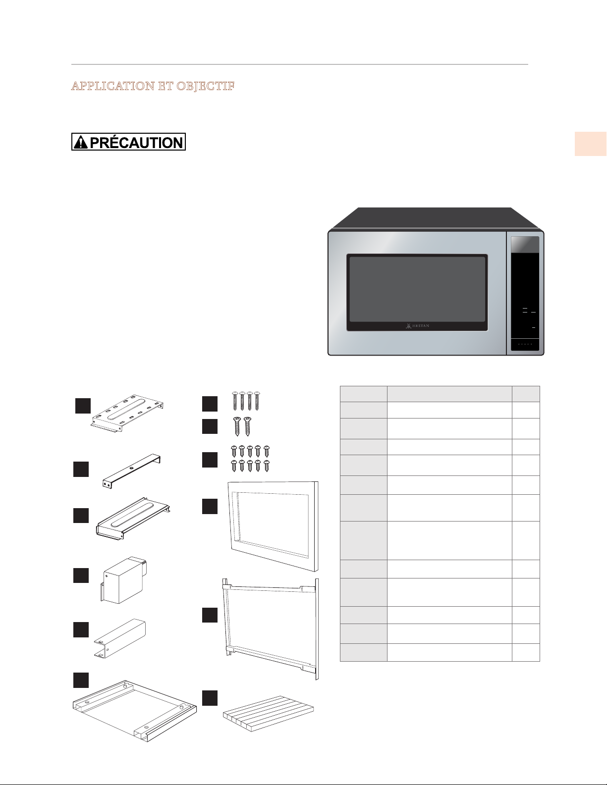
APPLICATION ET OBJECTIF
Le kit intégrés AKMWCK27, AKMWCK30 sont approuvés UL pour permettre l’installation
de certains fours à micro-ondes au-dessus de tout four mural électrique. Veuillez consulter le
Manuel d'Utilisation pour les types d'installations intégrées approuvées.
Ce kit intégré est conçu pour et approuvé uniquement pour les fours à micro-ondes HESTAN
spécifiant le kit intégré AKMWCK27 ou AKMWCK30, tel que KMWC24. Reportez-vous au
Manuel d'Utilisation du four à micro-ondes à convection ou à www.hestanhome.com.
VEUILLEZ LIRE ATTENTIVEMENT CES
INSTRUCTIONS AVANT DE COMMENCER
L'INSTALLATION!
FR
Veuillez toujours DÉBRANCHER LA FICHE du four
à micro-ondes de la prise électrique avant d'installer
le kit intégré. Retirer le plateau tournant de la cavité
du four.
Le kit intégré comprend des parties métalliques,
il faut donc faire preuve de prudence lors de la
manipulation et de l'installation afin d'éviter
d'éventuelles blessures.
A
DUCT (A)-1
G
H
I
B
DUCT (A)-2
J
C
DUCT (A)-3
SENSOR
REHEAT
POPCORN
SENSOR
1 BAKED POTATOES
2 FROZEN VEGETABLES
3 FRESH VEGETABLES-SOFT
4 FRESH VEGETABLES-HARD
5 FROZEN ENTREES
6 HOT DOGS
7 BACON
8 FISH, SEAFOOD
CONVECTION
1 HAMBURGERS
2 CHICKEN PIECES
3 STEAKS
4 FISH STEAKS
1 CHICKEN
2 TURKEY
3 TURKEY BREAST
4 PORK
1 BUNDT CAKE
2 COOKIES
3 MUFFINS
4 FRENCH FRIES
CONV.
PREHEAT BROIL
BAKE
LOW MIX
SLOW
BAKE
COOK
2 3
1
150ºF 275ºF
100ºF
6
7
8
350ºF
375ºF
400ºF
KITCHEN
CLOCK
TIMER
POWER
LEVEL
ARTICLE NOMS DES PIÈCES QTÉ
A CONDUIT (A)-1
B CONDUIT (A)-2
C CONDUIT (A)-3
D CONDUIT (B)
E CONDUIT (C)
F
ASSEMBLAGE DU
CONDUIT INFÉRIEUR
1
1
1
1
1
1
VIS À TÔLE À TÊTE
G
CYLINDRIQUE LARGE
4
M3.9 - 16 MM, ZINC
HELP
MENU
EXTRA
MINUTE
DEFROST
SENSOR
COOK
AUTO
BROIL
AUTO
ROAST
AUTO
BAKE
HIGH MIX
ROAST
5
4
325ºF
300ºF
0
9
450ºF
425ºF
STOP
CLEAR
START
D
H VIS À BOIS
VIS POUR ARMOIRE/
I
DUCT (B)
K
E
DUCT (C)
F
L
K CADRE ARRIÈRE
L FICHE DE COUSSIN
Veuillez vérifier la liste des pièces lors du
déballage.
Remarque : Les pièces J. Cadre Avant et K.
TRANSPARENT
J CADRE AVANT
2
10
1
1
1
Cadre Arrière sont expédiées attachées.
Veuillez les détacher avant l'installation.
©2019 Hestan Commercial Corporation
2
Page 12
CONDUIT (BC)
VIS (I)
VIS (I)
CONDUIT (A)-1
FR
INSTRUCTIONS D'INSTALLATION
(SUITE)
ÉTAPE 1 OUVERTURE DE L'ARMOIRE OU DU MUR
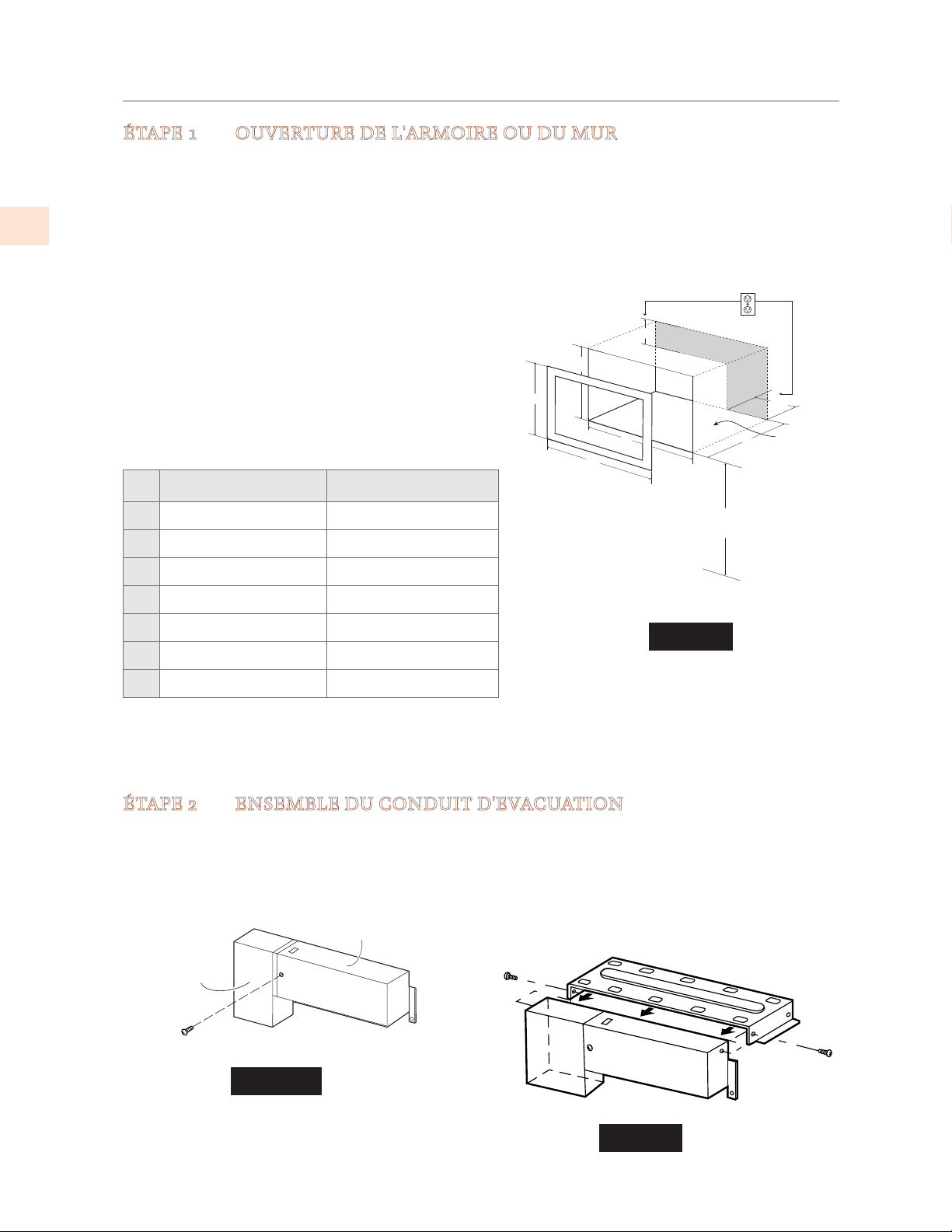
Faire une ouverture dans le mur ou l'armoire comme
illustré à la Figure 1. La profondeur doit être d'une
longueur minimum de 51,1 cm [20-1/8 po]. Si la
profondeur (E) dépasse 53,3 cm [21 po], l'emplacement
de la prise peut être situé n'importe où sur le mur arrière.
Le plancher de l'ouverture doit être construit dans un
contreplaqué assez fort pour supporter le poids du four
et sa propre charge (environ 45 kg [100 lbs]) et doit être
situé à un niveau convenable pour l'utilisation du four.
REMARQUE : Bien que le bon fonctionnement du four
n'exige pas que l'ouverture soit close (avec cloisons
latérales, arrière et plafond), le code local pourrait
l'exiger; il est donc suggéré de vérifier ce point.
L'ouverture du mur ou de l'armoire doit respecter les
dimensions suivantes et être centrée horizontalement
dans l'armoire.
AKMWCK27 AKMWCK30
La prise NE doit PAS se trouver dans l'aire ombrée
comme illustré à la Schéma 1.
REMARQUE: Si la profondeur (E) dépasse 21 po
[53,3 cm], l'emplacement de la prise peut être situé
n'importe où sur le mur arrière.
C
A
B
F
G
D
E
D’OUVERTURE
PLANCHER
A 20 po [50,8 cm] 20 po [50,8 cm]
B 26-7/8 po [68,3 cm] 29-7/8 po [75,9 cm]
C 18-1/2 po [47 cm] 18-1/2 po [47 cm]
D 25-1/4 po [64,1 cm] 25-1/4 po [64,1 cm]
REMARQUE: Le
plancher de l'ouverture
doit former un angle
90° avec le cadre de
façade de l'armoire.
E Min. 20-1/8 po [51,1 cm] Min. 20-1/8 po [51,1 cm]
F 5 po [12,7 cm] 5 po [12,7 cm]
G 10 po [25,4 cm] 10 po [25,4 cm]
ÉTAPE 2 ENSEMBLE DU CONDUIT D'EVACUATION
A. Insérer le bord du CONDUIT (B) dans le joint à lèvre
du CONDUIT (C). Les fixer ensemble à l’aide d’une
VIS (I) fournis dans le kit. Voir Schéma 2.
CONDUIT (C)
B. Placer le CONDUIT (A)-1 au dessus du four en
insérant le bord de l’ensemble du CONDUIT (BC) dans
la lèvre du CONDUIT (A)-1. Serrer deux VIS (I) pour
fixer le CONDUIT (A)-1 à l’ensemble du CONDUIT
(BC). Voir Schéma 3.
34-1/2 po
[87,6 cm] MIN.
Schéma 1
PLANCHER
CONDUIT (B)
VIS (1)
3
©2019 Hestan Commercial Corporation
Schéma 2
Schéma 3
Page 13
INSTRUCTIONS D'INSTALLATION
(SUITE)
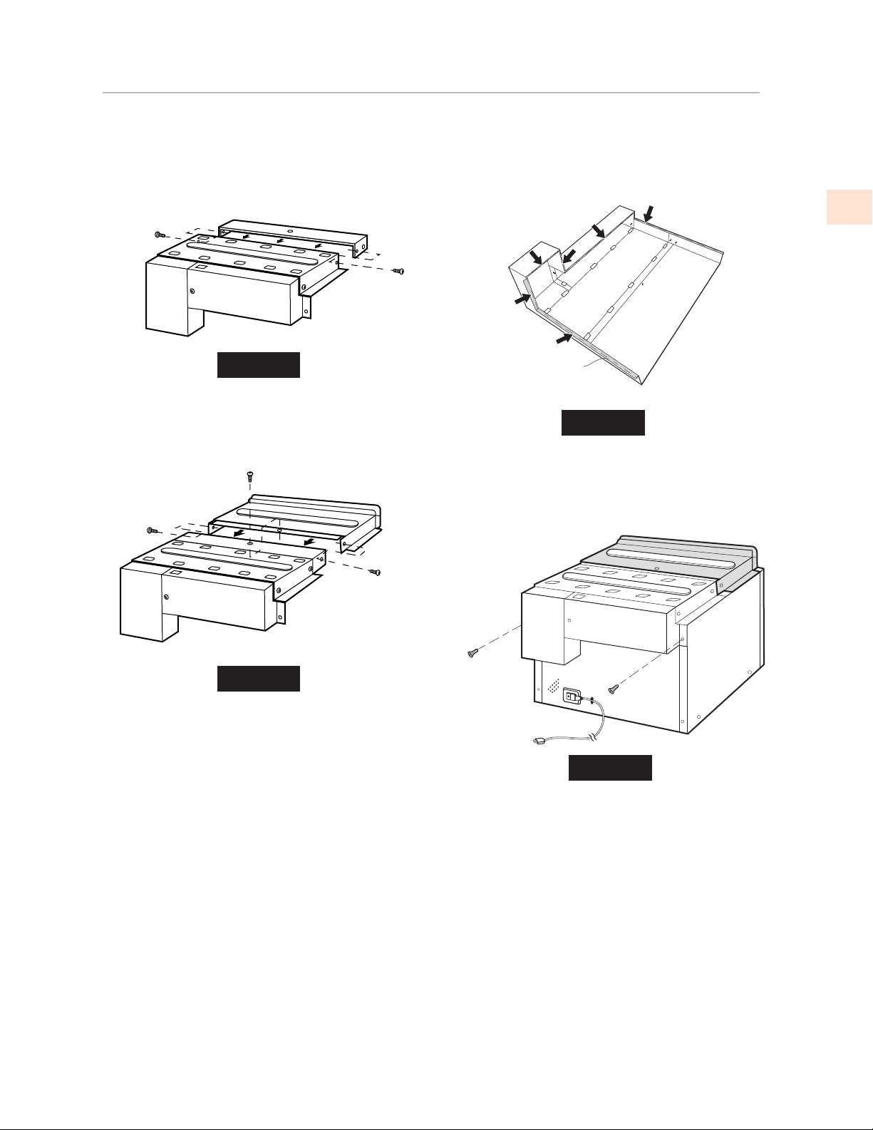
C. Placer le CONDUIT (A)-2 au dessus du four et
l’insérer dans le joint à lèvre du CONDUIT (A)-1.
Fixer le CONDUIT (A)-2 au CONDUIT (A)-1 à l’aide
de deux VIS (I) fournies. Voir Schéma 4.
.
VIS (I)
Schéma 4
CONDUIT (A)-2
CONDUIT (A)-1
D. Placer le CONDUIT (A)-3 au dessus du four et
l’insérer dans le CONDUIT (A)-2. Fixer le CONDUIT
(A)-3 à l’aide de trois VIS (I) fournies. Voir Schéma 5.
VIS (I)
VIS (I)
CONDUIT (A)-3
E. Tourner avec précaution sur l'assemblage
d'échappement. Retirer support adhésif COUSSIN L.
Appliquer les coussins aux brides de l'ensemble conduit
comme indiqué par les flèches. Voir Schéma 6.
FR
VIS (I)
COUSSINS (L)
Schéma 6
F. Retirer la VIS des coins supérieurs droit et gauche à
l'arrière du four. Placer l'ensemble conduit au-dessus de
l'appareil comme illustré et fixer l'ensemble conduit sur
le four à l'aide des deux vis qui viennent d'être retirées.
Voir Schéma 7.
VIS (I)
CONDUIT (A)-2
VIS
Schéma 5
VIS
Schéma 7
©2019 Hestan Commercial Corporation
4
Page 14
GE
DU CONDUIT
INSTRUCTIONS D'INSTALLATION
(SUITE)
ÉTAPE 3 INSTALLATION DE LA SURFACE
FR
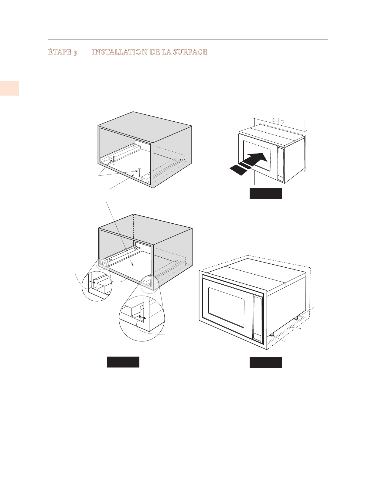
A. ASSEMBLAGE DU CONDUIT INFÉRIEUR Placer le
conduit inférieur au centre de l'ouverture de sorte que
l'écart « A » soit égal à l'écart « B ». Lorsque l'assemblage
du conduit inférieur est placé correctement, le rebord
avant du conduit sera aligné avec le devant de l'armoire.
Fixer à l'aide des 2 VIS (H). Voir Schéma 8.
VIS (H)
ASSEMBLAGE DU
CONDUIT INFÉRIEUR
B. INSTALLATION DANS L'ARMOIRE : Placer le
four près de l'ouverture du mur ou de l'armoire.
Brancher le cordon d'alimentation dans la prise
électrique. Guider avec précaution le four assemblé
dans l'ouverture préparée. Faire glisser le four sur
l'assemblage du conduit inférieur. Voir Schéma 9.
Schéma 9
C. INSTALLATION DANS L'ARMOIRE : Éviter de pincer
le cordon entre le four et le mur. Ajuster la position
du four de façon à ce que ses pattes entrent dans
les trous de l'assemblage de conduit inférieur. Voir
Schéma 10.
ÉCART « A »
DÉTAIL A
REMARQUE:
Centrer l’Assemblage du
Conduit Inférieur dans
l’ouverture de manière à ce
que les écarts A, B soient
égaux.
Schéma 8
DÉTAIL B
ÉCART « B »
Schéma 10
PATTE
ASSEMBLA
INFÉRIEUR
RENFONCEMENT
DU CONDUIT
5
©2019 Hestan Commercial Corporation
Page 15
TROUS DE FIXATION
TROUS DE FIXATION TROUS DE FIXATION
TROUS DE FIXATION
INSTRUCTIONS D'INSTALLATION
(SUITE)
D. DÉMONTAGE : Le CADRE AVANT (J) et le CADRE
ARRIÈRE (K) sont pré-assemblés avec des rotules
sphériques engagés dans les récepteurs.
• Pour séparer le CADRE AVANT du CADRE
ARRIÈRE:
a) Placez l'ensemble face vers le bas sur une
surface protégée.
b) À l'emplacement du pion à bille, insérez
un tournevis à tête plate entre le CADRE
AVANT et le CADRE ARRIÈRE et tirez
doucement pour dégager le rotule
sphérique du récepteur.
c) Répétez pour chaque coin. Voir Schéma
11.
F. INSTALLATION DU CADRE AVANT :
a) Poser le CADRE AVANT sur le CADRE
ARRIÈRE et aligner les rotules sphériques avec les
récepteurs.
b) Fixer le CADRE DE FAÇADE en le poussant
fermement contre le CADRE ARRIÈRE et en
engageant les quatre (4) fixations encliquetables.
Voir Schéma 13.
FIXATION
ENCLIQUETABLE
FR
Schéma 11
E. INSTALLATION DU CADRE ARRIÈRE : Placer le cadre
arrière à distances égales de haut en bas et de chaque
côté. Tracer l'emplacement de 4 trous au centre à
l'aide d'un poinçon et prépercer à l'aide d'une mèche
de 1,45 mm [1/16 po]. Fixer le cadre à l'aide de 4 VIS
(G). Voir Schéma 12
.
ÉCART ÉGAL DE
CHAQUE CÔTÉ
ÉCART ÉGAL DE HAUT EN BAS
Schéma 13
Schéma 12
©2019 Hestan Commercial Corporation
6
Page 16

RETAIN THIS MANUAL FOR FUTURE REFERENCE
CONSERVEZ CE MANUEL POUR UNE RÉFÉRENCE FUTURE
Hestan Commercial Corporation
3375 E. La Palma Ave.
Anaheim, CA 92806
(888) 905-7463
©2019 Hestan Commercial Corporation P/N 027837 REV A
TINSKB270MRR0
 Loading...