

hestan KGC User & Installation Manual

INDOOR COOKING
Drop-in Gas Cooktop
KGC
Installation Manual
SAFETY DEFINITIONS
READ THESE INSTRUCTIONS CAREFULLY AND COMPLETELY BEFORE INSTALLING OR USING
YOUR APPLIANCE TO REDUCE THE RISK OF FIRE, BURN HAZARD, OR OTHER INJURY. KEEP
THIS MANUAL FOR FUTURE REFERENCE.
CAUTION
NOTICE
Do not store or use gasoline or other flammable vapors and liquids in the vicinity
of this or any other appliance.
WHAT TO DO IF YOU SMELL GAS:
1) Do not try and light any appliance.
2) Do not touch any electrical switch.
3) Do not use any phone in your building.
4) Immediately call your gas supplier from a neighbor’s phone. Follow the gas
supplier’s instructions.
5) If you cannot reach your gas supplier, call the fire department.
Installation and service must be performed by a qualified installer, service agency,
or the gas supplier.
IF THE INFORMATION IN THIS MANUAL IS NOT FOLLOWED
EXACTLY, A FIRE OR EXPLOSION MAY RESULT CAUSING
PROPERTY DAMAGE, PERSONAL INJURY, OR DEATH.
INSTALLER: LEAVE THIS MANUAL WITH THE OWNER OF THE APPLIANCE.
HOMEOWNER: RETAIN THIS MANUAL FOR FUTURE REFERENCE.
THIS INDICATES THAT DEATH OR SERIOUS INJURY MAY OCCUR
AS A RESULT OF NOT OBSERVING THIS WARNING.
THIS INDICATES THAT MINOR OR MODERATE INJURY MAY
OCCUR AS A RESULT OF NOT OBSERVING THIS WARNING.
THIS INDICATES THAT DAMAGE TO THE APPLIANCE OR
PROPERTY MAY OCCUR AS A RESULT OF NOT OBSERVING THIS
WARNING.
©2018 Hestan Commercial Corporation
1
EN
When properly cared for, your Hestan appliance will provide safe, reliable service for many
years. When using this appliance, basic safety practices must be followed as outlined below.
IMPORTANT: Save these instructions for the local Gas or Utility Inspector’s use.
INSTALLER: Please leave these Installation Instructions with the owner.
OWNER: Please retain these Installation Instructions for future reference.
This cooktop is designed for residential use only.
Do NOT install this cooktop outdoors.
SAFETY PRECAUTIONS - BEFORE YOU BEGIN
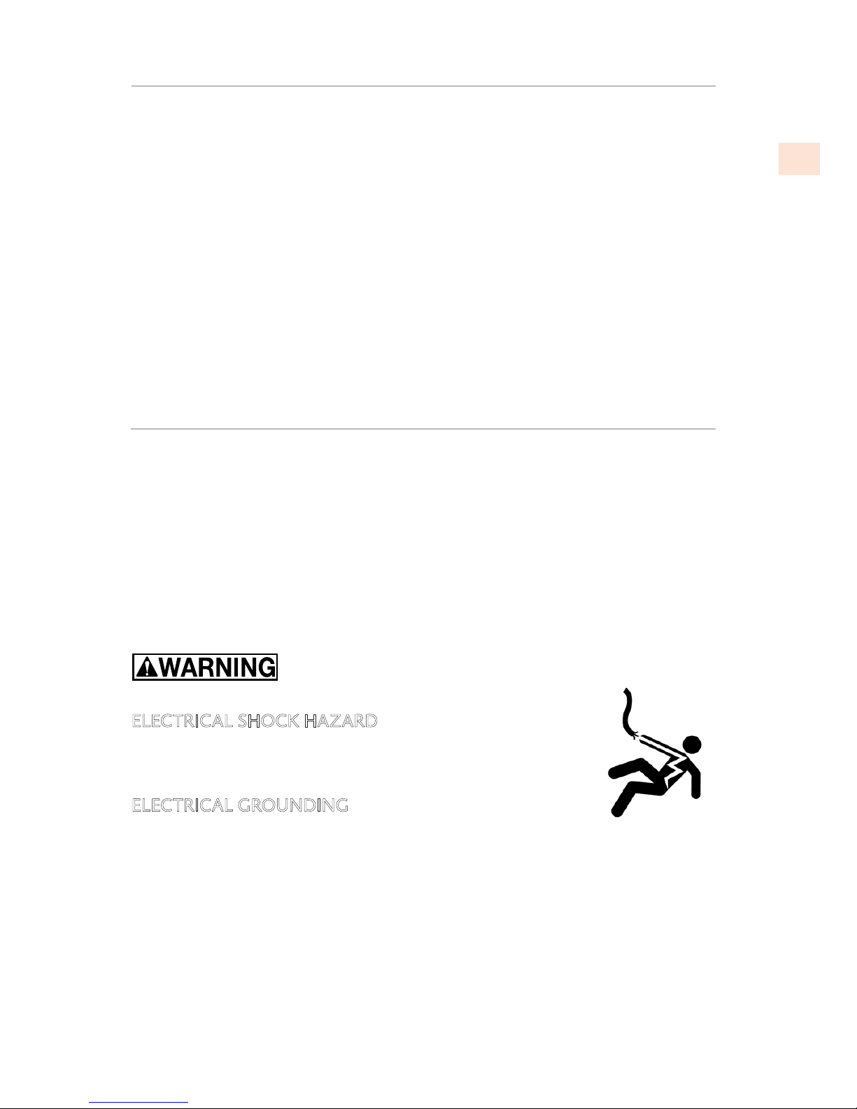
ELECTRICAL SHOCK HAZARD
Disconnect power before installing or servicing appliance. Before turning
power ON, be sure all controls are in the OFF position. Failure to do so
can result in death or electrical shock.
ELECTRICAL GROUNDING
This appliance must be grounded. Grounding reduces the risk of electric
shock in the event of a short circuit. Read the ELECTRICAL CONNECTIONS section of this
manual for complete instructions.
TABLE OF CONTENTS
1 SAFETY PRECAUTIONS - BEFORE YOU BEGIN
2 MODELS AND RATINGS
3 RATING LABEL
3 REGULATORY / CODE REQUIREMENTS
4 LOCATION AND INSTALLATION
12 GAS CONNECTION
16 ELECTRICAL CONNECTION
17 VENTILATION REQUIREMENTS
18 GAS CONVERSION
22 FINAL SETUP
25 PARTS LIST
25 SERVICE
©2018 Hestan Commercial Corporation
2
EN
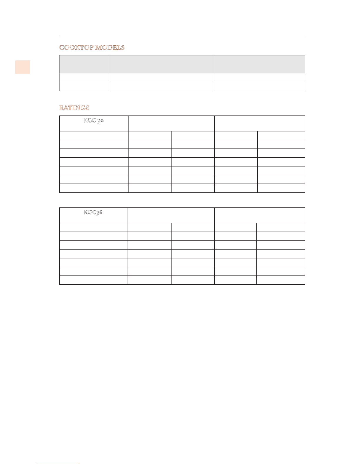
MODELS AND RATINGS
COOKTOP MODELS
MODEL NO. DESCRIPTION
CIRCUIT BREAKER
REQUIRED
KGC30 NG / -LP 30” DROP-IN GAS COOKTOP 15 Amp
KGC36 NG / -LP 36” DROP-IN GAS COOKTOP 15 Amp
RATINGS
KGC 30
POWER Btu/h with NG
at 5inch W.C.
POWER Btu/h with LP
at 10inch W.C.
Zones max flow rate min flow rate max flow rate min flow rate
Front right 8000 1300 6000 1300
Front left 8000 1300 6000 1300
Rear left 10500 2200 10500 2200
Rear right 10500 2200 10500 2200
Center – simmer 850 850
Center – main flame 20000 20000
KGC36
POWER Btu/h with NG
at 5inch W.C.
POWER Btu/h with LP
at 10inch W.C.
Zones max flow rate min flow rate max flow rate min flow rate
Front right (Stacked B) 15000 1300 15000 1300
Front left (Stacked B) 15000 1300 15000 1300
Rear left (Stacked B) 15000 1300 15000 1300
Rear right (Stacked B) 15000 1300 15000 1300
Center – simmer 850 850
Center – main flame 20000 20000
©2018 Hestan Commercial Corporation
3
EN
REGULATORY / CODE REQUIREMENTS
Installation of this cooking appliance must be made in accordance with local codes. In the
absence of local codes, this unit should be installed in accordance with the National Fuel
Gas Code
ANSI Z223.1/NFPA 54
, Natural Gas and Propane Installation code
CSA B149.1
, or
Propane Storage and Handling Code
B149.2
.
All Electrical Components must be electrically grounded in accordance with local codes or
in the absence of local codes with the National Electrical Code
ANSI/NFPA 70
, or Canadian
Electrical code
CSA C22.1
.
STATE OF MASSACHUSETT S
Massachusetts requires all gas be installed using a plumber or gas fitter carrying the appropriate
Massachusetts license. All permanently installed natural gas or propane installations require a
T handle type manual gas valve be installed in the gas supply line to this appliance. Flexible gas
connector must not be longer than 36” [91.4 cm].
CALIFORNIA PROPOSITION 65 - WARNING
WARNING This product can expose you to chemicals including carbon
monoxide, which is known to the State of California to cause cancer.
For more information, go to www.P65Warnings.ca.gov.
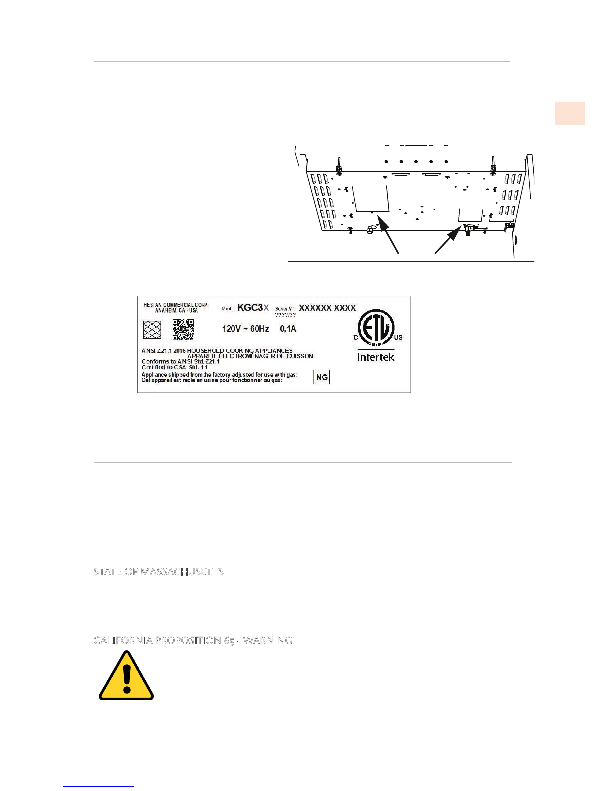
RATING LABEL
There are two rating labels on the unit. The main label contains important information about your
Hestan appliance such as the model and serial number, gas type and electrical rating.
Both rating labels are located in the bottom of the cooktop unit. Make sure you record your
model number and serial number for future use. The second rating label contains information
about the gas requirements and usage.
If service is necessary, contact Hestan
Customer Care with the model and serial
number.
Figure 1.
Rating Label Locations
KGCXX
HESTAN COMMERCIAL CORP.
ANAHEIM, CA - USA
XXX XXXXXX
xxxxxxxxx
xxxxxxxxx
xxxxxxxxx
Figure 2.
Sample Rating Label
©2018 Hestan Commercial Corporation
4
EN
LOCATION AND INSTALLATION
PLACEMENT
Check location where cooktop will be installed. The location should be away from strong drafty
areas, such as windows, doors and strong heating vents or fans.
UNPACKING
Do not remove the plastic film covering the stainless-steel surfaces. This film protects the finish
from scratches until the appliance is installed in its final position.
PR EPARATION
Electrical grounding is required. See “ELECTRICAL CONNECTION” on page 16 .
Assure that electrical installation is adequate and in conformance with National Electrical Code,
ANSI/NFPA 70 - latest edition**, or Canadian Electrical Code, part 1 C22.1 (latest edition)*** and
all local codes and ordinances.
Assure that the gas connection conforms with local codes and ordinances. In the absence of local
codes, installations must conform with American National Standard, National Fuel Gas Code ANSI
Z223/NFPA 54 - latest edition** Canadian CAN/CGA_B 149.1 or CAN/CGA-149.2 latest edition**
Copies of the standards listed may be obtained from:
** National Fire Protection Association
One Batterymarch Park
Quincy, Massachusetts 02169-7471
*** CSA International
8501 East Pleasant Valley Rd.
Cleveland, OH 44131-5575
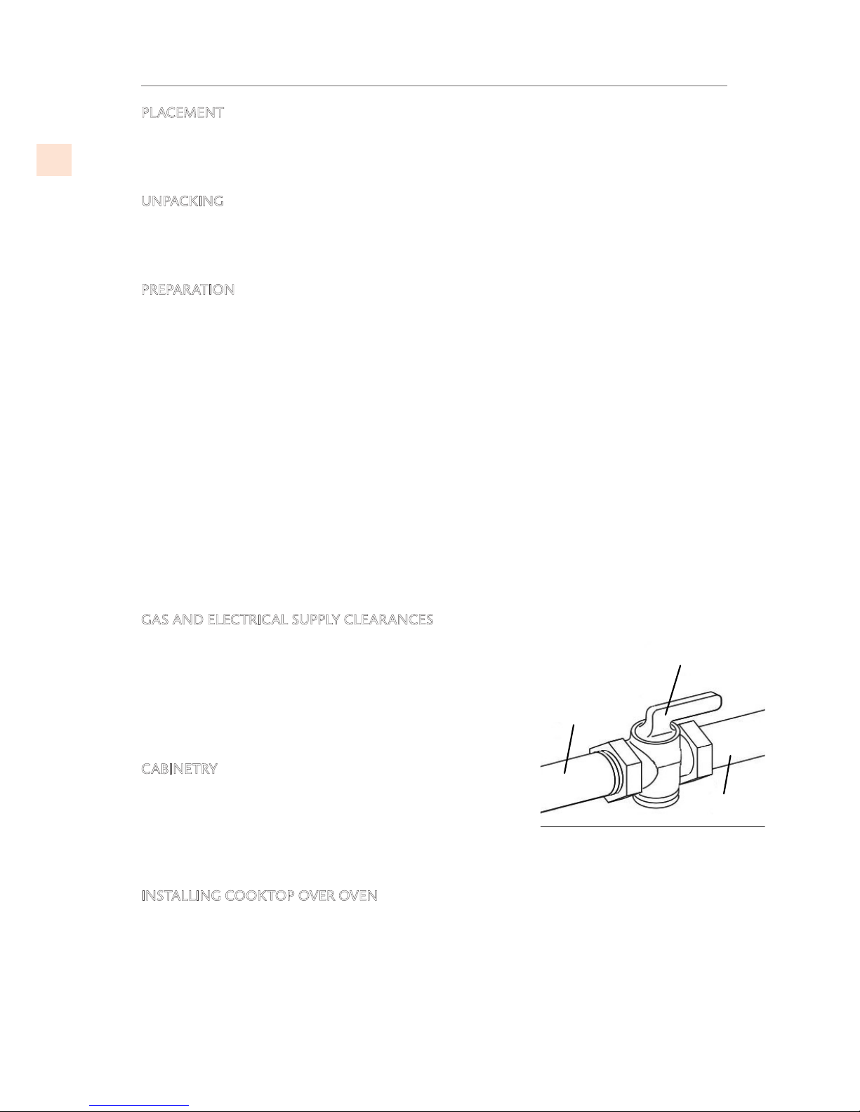
GAS AND ELECTRICAL SUPPLY CLEARANCES
If not already in place, install a gas shut-off valve in an easily
accessible location for servicing of the cooktop. Make sure
all users of the cooktop know where this shut-off is located,
and how to shut off the gas. Any openings in the wall or
floor behind the appliance must be sealed. See
Figure 8
and
Figure 9
on page6 for cutouts and clearances.
CABINETRY
To eliminate the risk of burns or fire by reaching over heated
surface units, cabinet storage space located above the
surface units should be avoided. If cabinet storage is to be
provided, the risk can be reduced by installing the required
vent hood that projects horizontally a minimum of 5” [12.7 cm]
beyond the bottom of the cabinets.
INSTALLING COOKTOP OVER OVEN
Only certain specified cooktop and oven models are approved for cooktop over oven installations.
Cooktops approved for this type of installation will have an approval label located on the outside
of the burner box. The label lists the cooktop and oven combinations that are approved for this
type of installation.
If you do not find this label, contact your dealer to confirm that the cooktop is approved for
installation over your model of oven.
GAS
SUPPLY
TO
APPLIANCE
SHUTOFF VALVE
IN OPEN POSITION
Figure 3.
Gas Shut-Off Valve
©2018 Hestan Commercial Corporation
5
EN
LOCATION AND INSTALLATION
(continued)
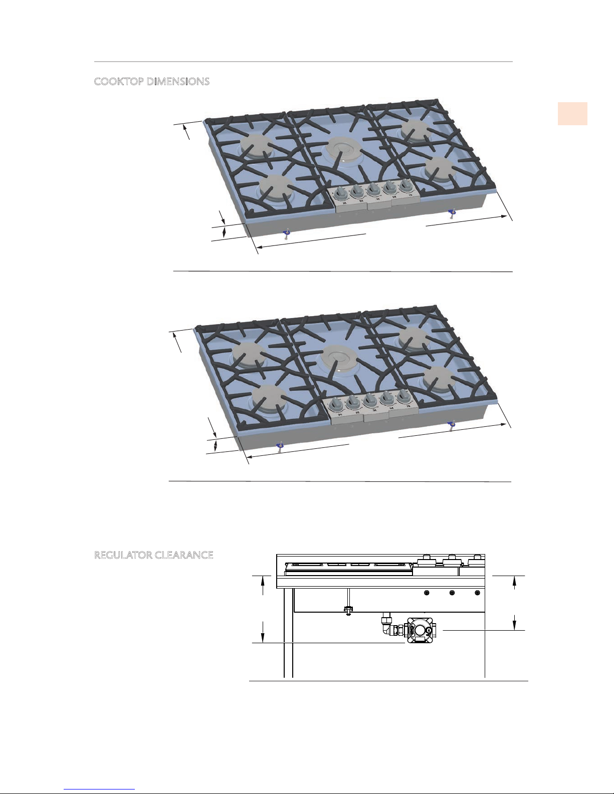
COOKTOP DIMENSIONS
REGULATOR CLEARANCE
The regulator may mounted to
the cooktop directly or via a
flexible (semi–rigid) stainless
steel gas hose with appropriate
end fittings.
(See “GAS CONNECTION” on
page 13 for more information)
30” [76 cm]
2-15/16”
[7,4 cm]
20-1/16” [51 cm]
Figure 4.
30” Model
36” [91 cm]
2-15/16”
[7,4 cm]
20-1/16” [51 cm]
Figure 5.
36” Model
6 1/4"
[159]
5 1/8"
[129]
Figure 6.
Regulator clearance
©2018 Hestan Commercial Corporation
6
EN
LOCATION AND INSTALLATION
(continued)
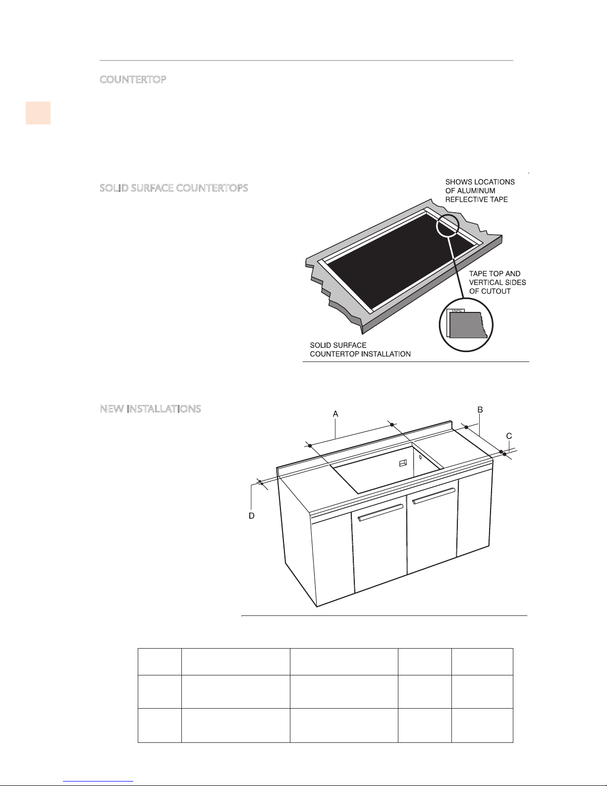
COUNTERTOP
1) Chamfer all exposed edges of decorative laminate to prevent damage from chipping.
2) Radius corners of cutout and file to ensure smooth edges and prevent corner cracking.
3) Recommend 1/4”or 3/8” diameter drill in each corner.
4) For solid surface countertops, refer to countertop material manufacturer instructions.
SOLID SURFACE COUNTERTOPS
Important: For solid surface material
installations such as Surel™ and Corian®,
consult with solid surface manufacturer.
Apply heat reflective tape such as Scotch®
Aluminum Foil Tape #425 or #427 around the
cutout so that it folds over on the top and
sides.
DO NOT WRAP THE TAPE UNDERNEATH
THE COOKTOP.
Be sure the tape extends beyond the
outermost flange of the cooktop. All corners
should be covered with tape.
NEW INSTALLATIONS
For new installations, the
minimum cut-out size is
preferable.
Figure 7.
Solid Surface Protective Tape
Figure 8.
Cutout Requirements (1/2)
Cooktop
Size
A B C D
30” MIN.29” [73.7 cm]
MAX.29-1/2” [75.0 cm]
MIN 19-5/8” [49.9 cm]
MAX 20” [50.8m cm]
MIN 2”
[5.0 cm]
MIN 3 1/2”
[9.0 cm]
36” MIN 35” [89.0 cm]
MAX 35-1/2” [90.2 cm]
MIN 19-5/8” [49.9 cm]
MAX 20” [50.8m cm]
MIN 2”
[5.0 cm]
MIN 3 1/2”
[9.0 cm]
©2018 Hestan Commercial Corporation
7
EN
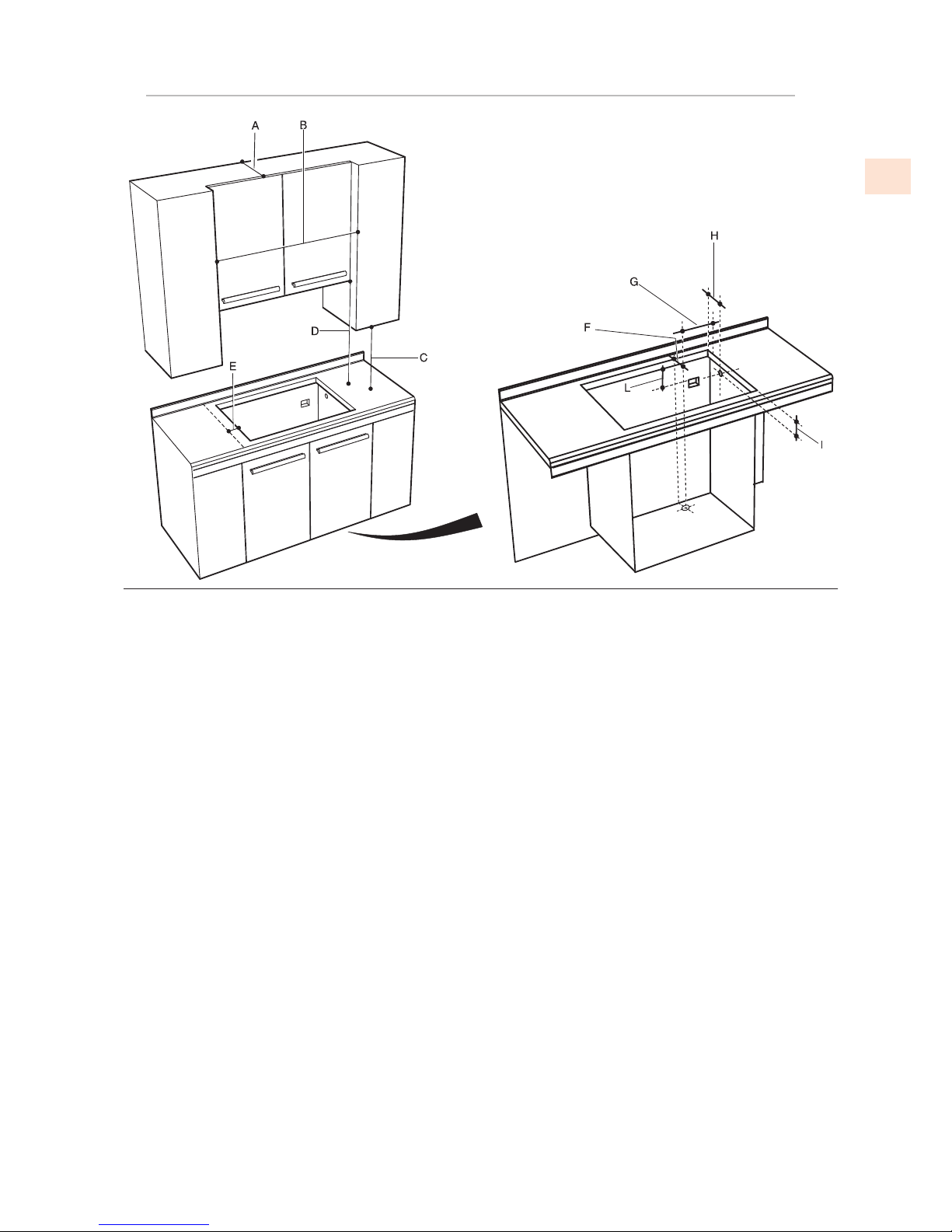
LOCATION AND INSTALLATION
(continued)
A 13” [33 cm) Depth of unprotected overhead
cabinets.
B 30” Model: 30” [76.2 cm] MIN.
36” Model: 36” [91.4 cm] MIN.
C 18” [47.7 cm] MIN. Height from countertop to nearest cabinet on either side of unit.
D 30” [76.2 cm ] MIN. (see Note*) Clearance from countertop to unprotected overhead surface.
E 5” [12.7 cm] min Clearance from cut out to side wall on the left and right of the unit.
F From the back corner of cut-out to hole center 2-9/32” [5.8 cm].
G From the right corner of cut-out to hole center 2-19/32” [6.6 cm].
H From the back corner of cut-out to hole center 1-1/4” [3.2 cm]. Opening with oven under
cooktop.
I From the top of countertop to hole center 6” [15.2 cm]. Opening with oven under cooktop.
L Electric outlet from bottom of counter top and adjacent to the cabinet side 12” [30.5 cm].
– Hole 1-1/5” [3 cm].
* NOTE
• If cabinet has a drawer, a 5-1/4”[3.2cm] depth clearance from the top of the countertop to the
top of the drawer (or other obstruction) in base cabinet is required. The drawer depth may
need to be shortened to avoid interfering with the regulator.
• 24” [61 cm] min. clearance if bottom of wood or metal cabinets is protected by not less than
1/4” [0.6cm] flame retardant millboard covered with not less than No. 28 MSG sheet steel
0.015” [0.04cm] stainless steel, or 0.024” [0.06 cm] aluminum or 0.020” [0.05 cm] copper.
30” [76.2cm] min. clearance between top of cooking platform and bottom of unprotected
wood or metal cabinet.
Figure 9.
Cutout Requirements (2/2)
©2018 Hestan Commercial Corporation
8
EN
LOCATION AND INSTALLATION
(continued)
MOBILE HOME INSTALLATION
The installation of this cooktop must conform to the Manufactured Home Construction and
Safety Standards, Title 24 CFR, Part 3280 (formerly the Federal Standard for Mobile Home
Construction and Safety;
Title 24 HUD part 280); or when such standard is not applicable, the Standard for
Manufactured Home Installations (Manufactured Home Sites, Communities and Setups), ANSI
A225.1 - latest edition, or with local codes.
In Canada, the installation of this cooktop must conform with the current standards CAN/
CSA-Z240 - latest edition, or with local codes.
The appliance should not be installed with a ventilation system that blows air downward
toward the range. This type of ventilation system may cause ignition and combustion
problems with the gas cooking appliance resulting in personal injury or unintended operation.
See the VENTILATION REQUIREMENTS section of this manual for more details.
©2018 Hestan Commercial Corporation
9
EN
LOCATION AND INSTALLATION
(continued)
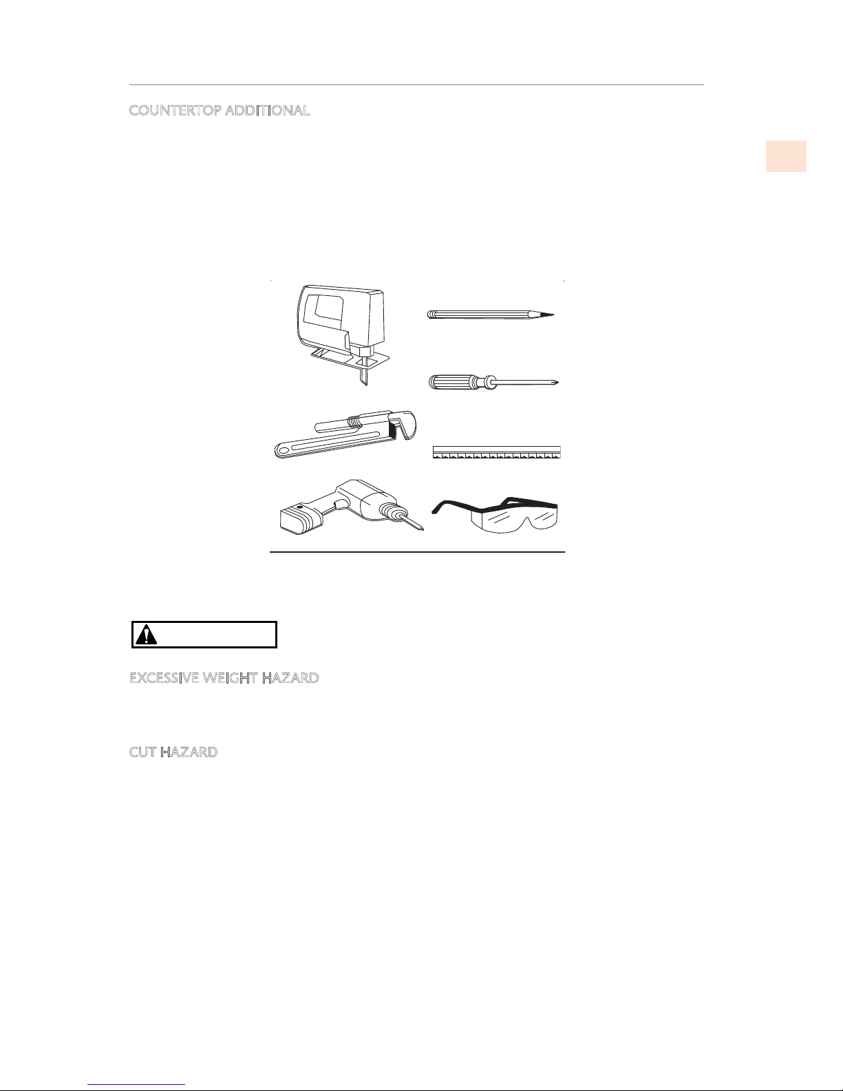
COUNTERTOP ADDITIONAL
Always consult the countertop manufacturer for specific instructions.
Ensure the countertop is square and level and ensure no structural members interfere with
space requirements.
Prepare the cut-out according to the instructions (see cut-out dimensions).
Make sure the wall coverings, countertop and cabinets around the cooktop can withstand heat
up to 200° F [93º C] .
CAUTION
EXCESSIVE WEIGHT HAZARD
Use two or more people to move and install cooktop.
Failure to do so can result in back or other injury.
CUT HAZARD
Beware of sharp edges. Use the polystyrene ends when carrying the product. Failure to use
caution could result in minor injury or cuts.
Figure 10.
Tools Required
©2018 Hestan Commercial Corporation
10
EN
LOCATION AND INSTALLATION
(continued)
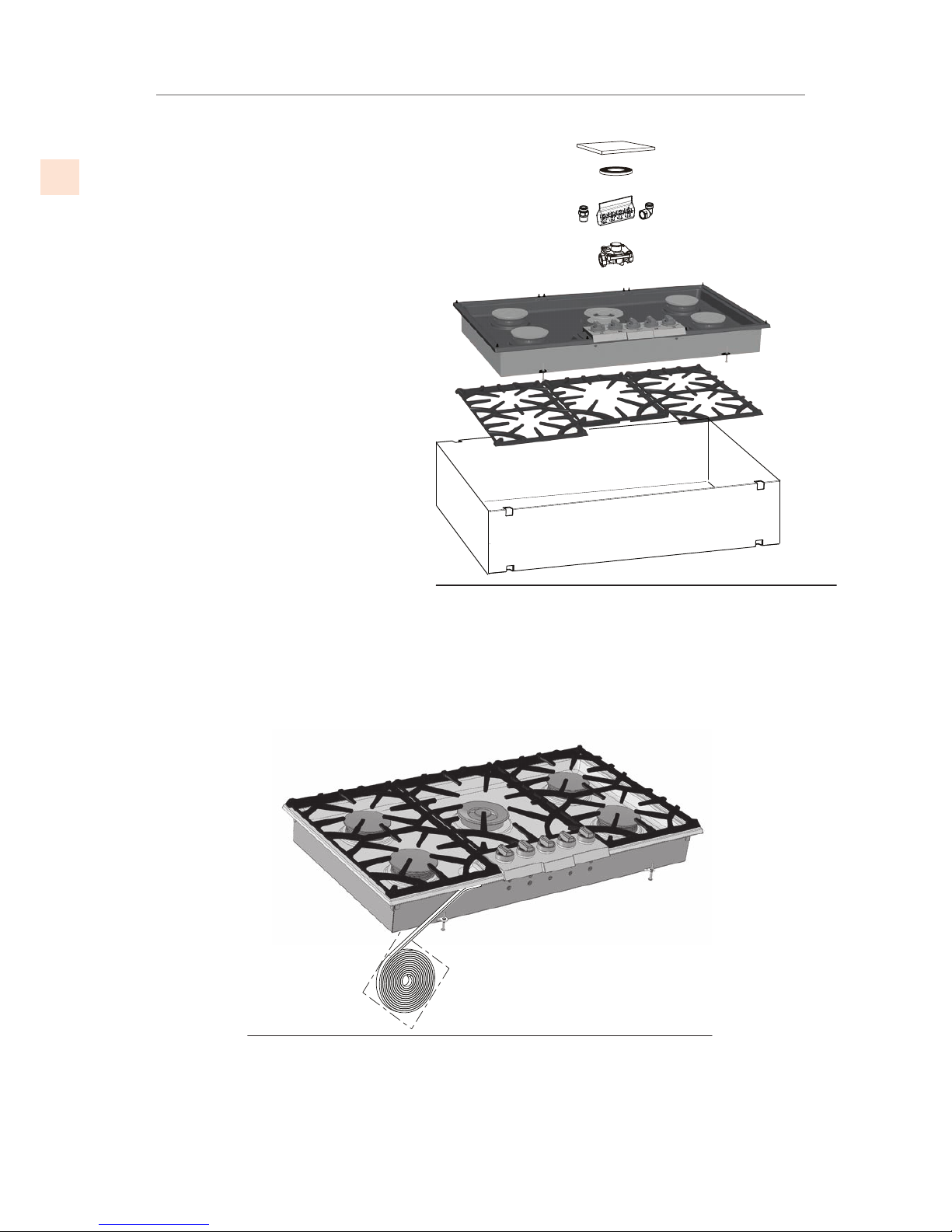
Step 1
Remove packaging materials and
literature package from the cooktop
before beginning installation.
Remove installation instructions from
literature pack and read them carefully
before you begin.
Step 2
Foam tape is provided to seal the
cooktop edges to the countertop. Apply the provided foam tape to the underside of the
cooktop edge.
Use tape around the entire cooktop perimeter.
Trim the tape ends so they meet closely.
MANUAL
GASKET
GAS CONVERSION KIT
GAS CONNECTION KIT
PRESSURE
REGULATOR
COOKTOP
GRATES
CARDBO
ARD
Figure 11.
Package Contents
Figure 12.
Apply Foam tape
©2018 Hestan Commercial Corporation
11
EN
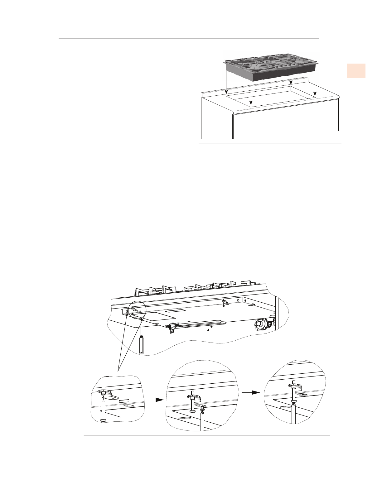
Step 3
Insert the cooktop centered into the cutout
opening.
Make sure the front edge of the counter top is
parallel to the cooktop. Make final check that
all required clearances are met.
Step 4
Four clamp brackets are provided with your unit.
After cooktop has been installed into the
countertop, install the brackets on the burner box as
shown in
Figure 14
.
Install the clamp brackets on the front and back of the
burner box bottom (if the cabinet construction does not provide clearance for installing brackets
at the front and back of the burner box, install the clamp brackets on the sides of the burner box).
Step A: place the clamping screws into brackets
Step B: attach brackets by using the attachment screws on the selected location of burner box,
tighten screws just enough to hold brackets in place
Step C: position brackets so that each clamp screw is in contact with the counter top bottom
Step D: tighten attachment screws securely.
Step E: check that the front edge of the cooktop is parallel to the front edge of the countertop
tighten the clamping screw against the countertop.
DO NOT OVER TIGHTEN.
Figure 13.
Place Cooktop
Figure 14.
Install and Secure Clamps
LOCATION AND INSTALLATION
(continued)
©2018 Hestan Commercial Corporation
12
EN
GAS SUPPLY
The local gas authority or supplier should be consulted at the installation planning stage in order
to establish the availability of an adequate supply of gas (NG or LP). If it is a new installation, have
the gas authorities or supplier check the meter size and piping to assure that the unit is supplied
with the necessary amount of gas supply and pressure to operate the unit(s).
• Gas connections should be made by a qualified plumber, or your professional appliance
installer.
• All appliances (NG or LP) must be fitted with an accessible upstream gas shutoff valve as a
means of isolating the appliance for emergency shut off and for servicing.
• Make certain new piping and connections have been made in a clean manner and have been
purged so that piping compound, chips, etc. will not clog regulators, valves, orifices, or
burners. Use pipe joint compound / thread sealant approved for natural and LP gases.
PRECAUTIONS FOR SUPPLY TESTING
The appliance and its individual manual shutoff valve must be disconnected from the gas supply
piping system during any pressure testing of that system at test pressures in excess of 1/2 psi
[3.5kPa].
The appliance must be isolated from the gas supply piping system by closing its individual manual
shutoff valve during any pressure testing of that system at test pressures equal to or less than
1/2psi [3.5 kPa].
NEVER CONNECT THE APPLIANCE TO AN UNREGULATED GAS
SUPPLY.
If the line pressure supplying the appliance pressure regulator exceeds 14 inches W.C. (any gas), an
external regulator must be installed in the gas line ahead of the appliance regulator to reduce the
pressure to no more than 14 inches W.C. Failure to do this can result in malfunction and damage
to the appliance.
GAS TYPE AND PRESSURE
Before proceeding, verify that the appliance is fitted for the type of fuel available. Connecting to
an improper gas type will result in poor performance and increased risk of damage or injury. Gas
type is shown on the rating label. If the appliance has been converted for an alternate fuel, that
information should be next to the rating label or near the regulator.
The gas should be supplied to the appliance’s pressure regulator at line pressure between 6 and 14
inches of water column for NG, and between 11 and 14 inches of water column for LP.
Installation of this cooking appliance must be made in accordance with local codes. In the absence
of local codes, this unit should be installed in accordance with the National Fuel Gas Code No.
Z223.1/ NFPA 54
, Natural Gas and Propane Installation code
CSA B149-1
, or Propane Storage and
Handling Code B149.2.
CONVERSION KITS
A conversion kit is provided with the cooktop. The conversion can only be performed by a
qualified technician. In the event your Hestan appliance needs to be converted from NG to LP, or
vice-versa, you will need to contact Hestan Customer Service to arrange a service call.
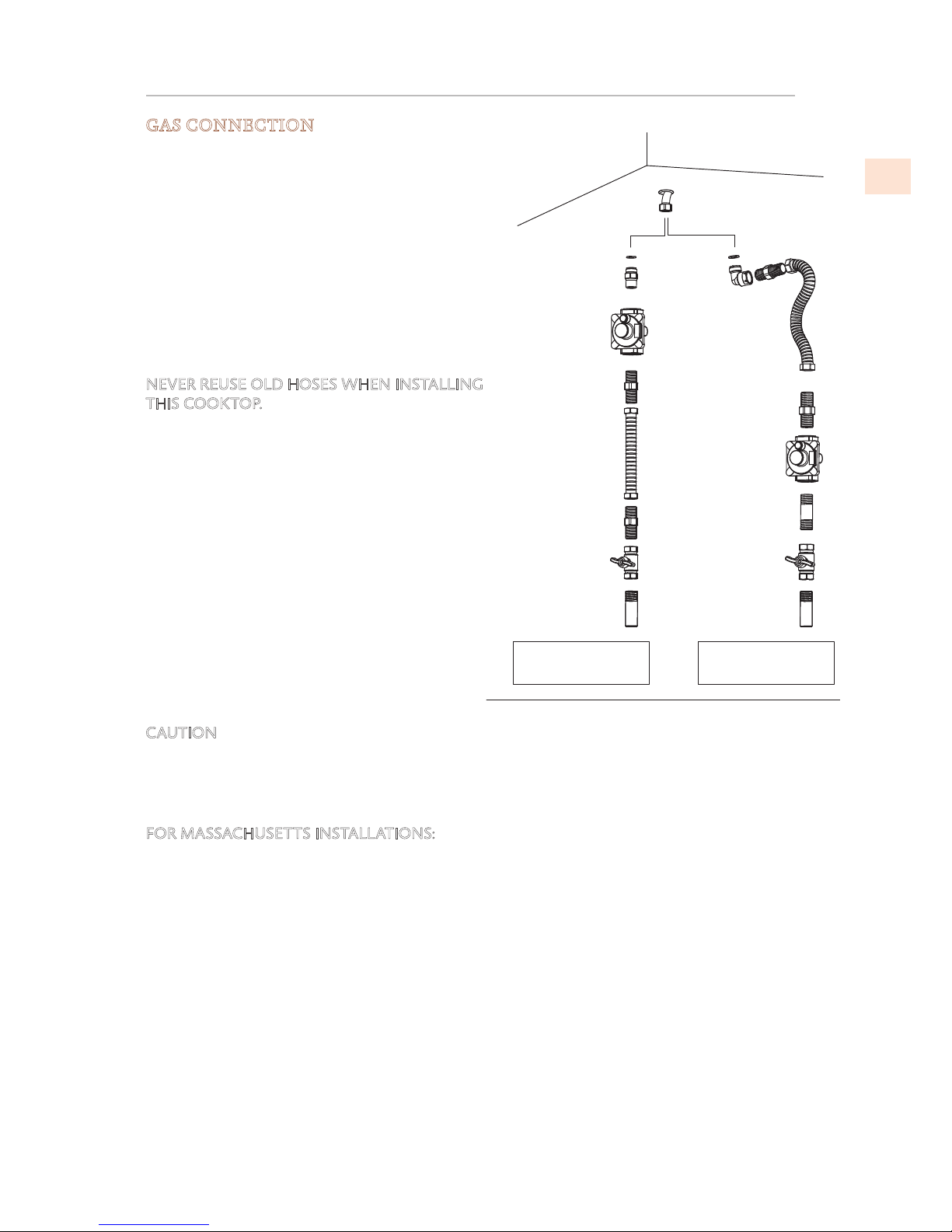
GAS CONNECTION
©2018 Hestan Commercial Corporation
13
EN
GAS CONNECTION
(CONTINUED)
GAS CONNECTION
After connecting, the installation must be
checked for leaks. That procedure is on the
following page.
Connect to gas supply using a minimum 1/2”
inside diameter flexible (semi–rigid) stainless steel
gas hose to prevent gas starvation. This hose
should be no more than 36” [91.4 cm] in length,
or as permitted by applicable codes. The included
regulator must be installed between the shutoff
valve and the appliance, and must be mounted so
that its directional arrow (flow direction) points
toward the gas manifold.
NEVER REUSE OLD HOSES WHEN INSTALLING
THIS COOKTOP.
ANSI Z21.24/CSA 6.10 and ANSI Z21.75/CSA
6.27 codes require that a new gas appliance hose
must be used for a new appliance, when moving
an appliance to a new location, or as a result of
damage.
Use the appropriate thread sealant on all NPT
connections. Do not apply sealant to flare
fittings.
NEVER TIGHTEN TO MORE THAN 35 ft lbs OF
TORQUE.
Check alignment of valves after connecting the
cooktop to the gas supply to be sure the manifold
pipe has not been moved. A misalignment could
cause the valve knob stem to rub on the control
panel, resulting in a gas leak at the valve.
CAUTION
Do not attempt to attach the flexible hose directly
to an external pipe thread.
Connection requires proper adapters to join the flex hose and the pipe fittings.
FOR MASSACHUSETTS INSTALLATIONS:
1. Shut-off valve must be a “T” handle gas cock.
2. Flexible gas hose must not be longer than 36 inch [91.4 cm].
3. Not approved for installation in a bedroom or a bathroom unless unit is direct vent.
MANIFOLD
ENTRANCE
GASKET
GASKET
FLARE
ADAPTOR
*****
ADAPTOR
--- to
1/2" NPT
ELBOW
1/2" NPT
PIPE NIPPLE
1/2" NPT PIPE
(STATIONARY
SUPPLY PIPE)
1/2" NPT PIPE
(STATIONARY
SUPPLY PIPE)
NO APPLIANCE
MOUNTED BELOW
THIS COOKTOP
WALL OVEN MOUNTED
IN CABINETRY BELOW
THIS COOKTOP
GAS
SHUT-OFF
VALVE
GAS
SHUT-OFF
VALVE
FLEXIBLE
GAS HOSE
36” MAX
(91.4 cm) MAX
FLEXIBLE
FLARE
ADAPTOR
FLARE
ADAPTOR
FLARE
ADAPTOR
APPLIANCE PRESSURE
REGULATOR, SUPPLIED
(OBSERVE GAS FLOW
DIRECTION)
APPLIANCE
PRESSURE
REGULATOR,
SUPPLIED (OBSERVE
DIRECTIONALITY
OF GAS FLOW)
GAS HOSE
36” MAX
(91.4 cm) MAX
Figure 15.
Typical Methods Of Connecting Gas
©2018 Hestan Commercial Corporation
14
EN
GAS CONNECTION
(CONTINUED)
LEAK TESTING
GENERAL
Although all gas connections on your Hestan appliance are leak tested at the factory prior to
shipment, a complete gas tightness check must be performed at the installation site due to
possible movement in shipment, or excessive pressure unknowingly being applied to parts of the
unit. Immediately check if the smell of gas is detected. Leak testing of the appliance shall be
conducted according to these instructions:
BEFORE TESTING
• Do not smoke while leak testing.
• Never leak test with an open flame.
• Make a soap solution of one part liquid detergent and one part water for leak testing purposes.
• Apply the solution to the gas fittings and flex hose by using a spray bottle or a brush.
TO TEST
• Make sure all control knobs are in the “OFF” position.
• Apply the soap solution to all fittings and flex hose.
• Turn the gas supply on.
• Check all connections from the supply line up to regulator connection at the rear of the
appliance.
• Soap bubbles will appear where a leak is present. If a leak is present, immediately turn off gas
supply, tighten any leaking fittings, turn the gas supply back on, and recheck.
• If you cannot stop a gas leak, turn off the gas supply and call the dealer where you purchased
your appliance.
• Do not use the appliance until all connections have been checked and do not leak.
TESTING APPLIANCE REGULATOR
When checking appliance regulator function, make certain that the correct pressure is supplied to
the regulator. For natural gas supply, between 6 and 14 inches of water column. If converted for
LP gas, between 11 and 14 inches.
To pressure test the regulator, select one of the side burners and connect to the orifice port, as
follows.
 Loading...