

hestan KEC 30, KEC 36 Installation Manual

INDOOR COOKING
Radiant Cooktop
KEC
Installation Manual
SAFETY DEFINITIONS
THIS INDICATES THAT DEATH OR SERIOUS INJURY MAY
OCCUR AS A RESULT OF NOT OBSERVING THIS WARNING
THIS INDICATES THAT MINOR OR MODERATE INJURY MAY
OCCUR AS A RESULT OF NOT OBSERVING THIS WARNING.
THIS INDICATES THAT DAMAGE TO THE APPLIANCE OR
PROPERTY MAY OCCUR AS A RESULT OF NOT OBSERVING
THIS WARNING.
NOTICE
READ THESE INSTRUCTIONS CAREFULLY AND COMPLETELY
BEFORE INSTALLING OR USING YOUR APPLIANCE TO REDUCE
THE RISK OF FIRE, BURN HAZARD, OR OTHER INJURY. KEEP
THIS MANUAL FOR FUTURE REFERENCE.
Do not store or use gasoline or other flammable vapors and liquids in the vicinity of
this or any other appliance.
Installation and service must be performed by a qualified installer or service agency.
DO NOT REPAIR, REPLACE OR REMOVE ANY PART OF THE APPLIANCE UNLESS
SPECIFICALLY RECOMMENDED IN THE MANUAL. IMPROPER INSTALLATION,
SERVICE OR MAINTENANCE CAN CAUSE INJURY OR PROPERTY DAMAGE. REFER
TO THIS MANUAL FOR GUIDANCE. ALL OTHER SERVICING SHOULD BE DONE BY A
QUALIFIED TECHNICIAN.
INSTALLER: LEAVE THIS MANUAL WITH THE OWNER OF THE APPLIANCE.
HOMEOWNER: RETAIN THIS MANUAL FOR FUTURE REFERENCE.
IF THE INFORMATION IN THIS MANUAL IS NOT FOLLOWED
EXACTLY, A FIRE OR EXPLOSION MAY RESULT CAUSING
PROPERTY DAMAGE, PERSONAL INJURY, OR DEATH.

©2018 Hestan Commercial Corporation
1
EN
When properly cared for, your Hestan appliance will provide safe, reliable service for many
years. When using this appliance, basic safety practices must be followed as outlined below.
IMPORTANT: Save these instructions for the local Utility Inspector’s use.
INSTALLER: Please leave these Installation Instructions with the owner.
OWNER: Please retain these Installation Instructions for future reference.
This appliance is NOT designed for installation in manufactured (mobile) homes or
recreational park trailers. Do NOT install this appliance outdoors.
SAFETY PRECAUTIONS - BEFORE YOU BEGIN
ELECTRICAL SHOCK HAZARD
Disconnect power before installing or servicing appliance. Failure to do so
can result in death or electrical shock.
ELECTRICAL GROUNDING
• This appliance must be grounded. Grounding reduces the risk of electric
shock in the event of a short circuit. Read the ELECTRICAL CONNECTIONS section of
the Installation manual for complete instructions.
• DO NOT ground to a gas pipe.
• DO NOT use an extension cord with this appliance.
• DO NOT have a fuse in the NEUTRAL or GROUNDING circuit. A fuse in the NEUTRAL
or GROUNDING circuit could result in an electrical shock.
TABLE OF CONTENTS
1 SAFETY PRECAUTIONS - BEFORE YOU BEGIN
2 MODEL NUMBERS
2 RATING LABEL
2 REGULATORY / CODE REQUIREMENTS
3 CUTOUT DIMENSIONS AND REQUIREMENTS
5 COOKTOP INSTALLATION
8 ELECTRICAL CONNECTIONS
10 FINAL SETUP
11 PARTS LIST
11 SERVICE
©2018 Hestan Commercial Corporation
2
EN
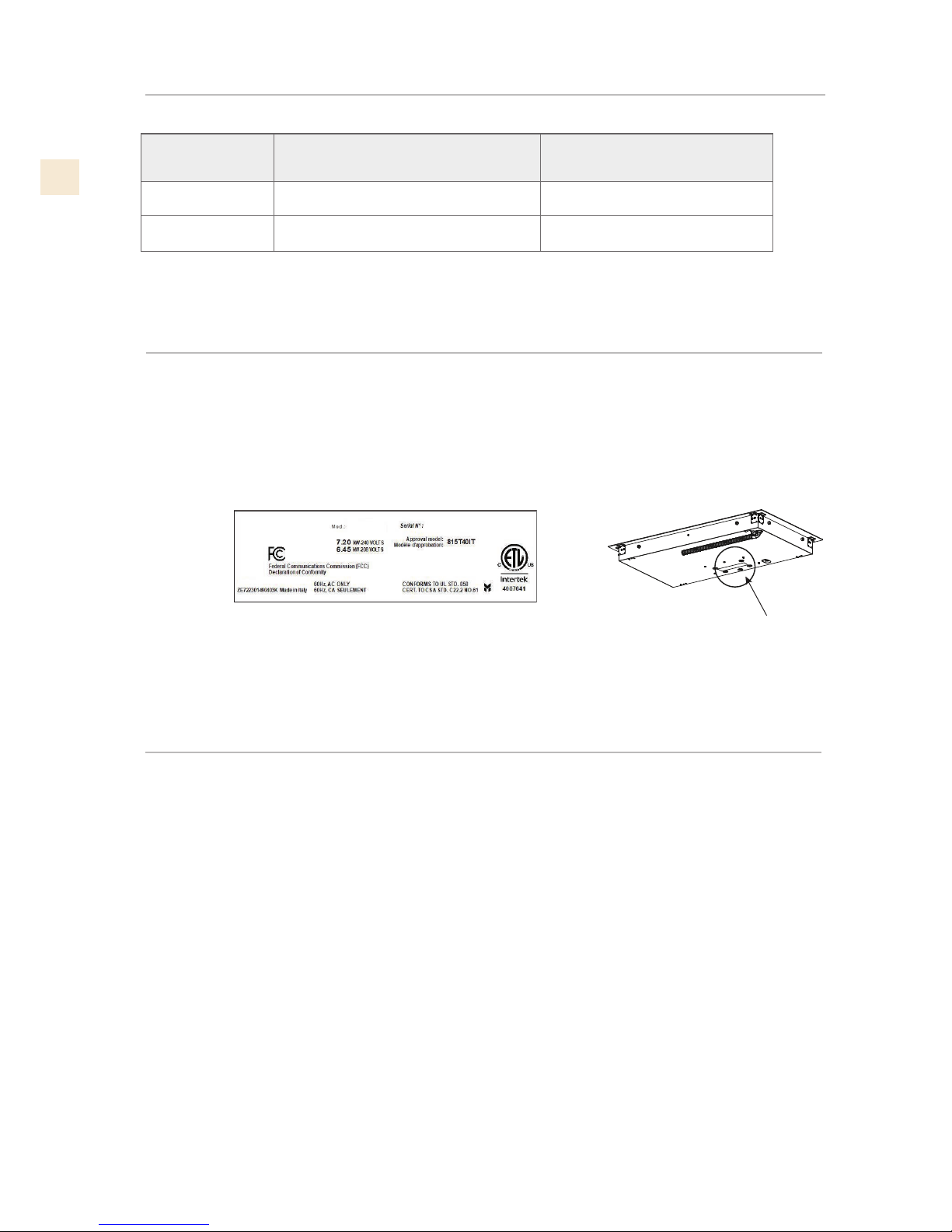
MODEL NUMBERS
RATING LABEL
The rating label contains important information about your Hestan appliance such as the model and
serial number, electrical rating and the minimum installation clearances.
The rating label is located on the bottom of the cooktop.
If service is necessary, contact Hestan Customer Care with the model and serial number information
shown on the label.
MODEL NO. DESCRIPTION
CIRCUIT BREAKER
REQ’D
KEC 30 30” Radiant Cooktop 40 Amp
KEC 30 30” Radiant Cooktop 50 Amp
REGULATORY / CODE REQUIREMENTS
Installation of this cooking appliance must be made in accordance with local codes. In the
absence of local codes, this unit should be installed in accordance with the National Electrical
Code and local codes.
This appliance must be electrically grounded in accordance with local codes or in the absence
of local codes with the National Electrical Code
ANSI/NFPA 70
, or Canadian Electrical code
CSA C22.1
.
RATING LABEL
SERIAL TAG
KEC30-BK
HESTAN COMMERCIAL CORP.
ANAHEIM, CA - USA
TYPICAL RATING LABEL
©2018 Hestan Commercial Corporation
3
EN
Figure 1.
30” 3/8
[77.1 cm]
21” 3/16
[53.8 cm]
3” 1/8
[7.9 cm]
36” 3/16
[91.9 cm]
21” 3/16
[53.8 cm]
3” 1/8
[7.9 cm]
30’’
36’’
A
B
SEE NOTE
R
C
UTOUT DIMENSION
Figure 2.
SLOT FOR
CABLE
ROUTING
3-1/2” [9 cm]
2-1/2” [6.5 cm]
LENGTH OF CUT
FROM EDGE OF CUTOUT
AND FRONT EDGE OF
COUNTERTOP
2-1/2” [6.5 cm]
1-1/4” [3.2 cm] Canadian
2-1/4” [5.7cm] US
LENGTH OF CUT
1-1/2” [3.8CM]
MIN CLEARANCE
CUTOUT DIMENSIONS AND REQUIREMENTS

©2018 Hestan Commercial Corporation
4
EN
D
G
C
E
F
13” [33 cm]
Depth of
unprotected
overhead
cabinets
2” [5 cm] min
Clearance
from cutout to
side wall on
the left and
right of the
unit
30” [76.2 cm]
min.
[see note*]
Clearance
from
countertop to
unprotected
overhead
surface
18” [45.7 cm]
min
Height from
countertop
to nearest
cabinet on
either side of
unit
A BCD E F G
30”
[76.2 cm] min
36”
[91.4 cm] min
19-1/4”
[49.0 cm]
19-5/8”
[49.8 cm]
19-1/4”
[49.0 cm]
19-5/8”
[49.8 cm]
28-11/16”
[72.9 cm]
28 15/16”
[73.5 cm]
34-1/16”
[86.5 cm]
34-5/16”
[87.2 cm]
CUTOUT
WIDTH
30”
[76.2cm]
36”
[91.4 cm]
Figure 3. Cutout dimensions and requirements
Under the cooktop it is necessary to install a partition
as shown ****
IMPORTANT
Important Preparation Suggestions
1. Chamfer all exposed edges of decorative laminate
to prevent damage from chipping.
2. Radius corners of cutout and file to insure
smooth edges and prevent corner cracking.
Recommend 1/4“or 3/8“diameter drill in each
corner.
3. Rough edges, inside corners which have not been
rounded and forced fits can contribute to cracking
of the countertop laminate.
This cooktop has been designed with wide
tolerances of cut-out for when another brand is
being replaced with a Hestan unit. For new
installations, we recommend holding to the
minimum cutout dimensions.
* NOTE
24” [61 cm] min. clearance if bottom of wood or metal
cabinets is protected by not less than 1/4” [0.6 cm] flame
retardant millboard covered with no less than No. 28 MSG
sheet steel 0.015” [0.04 cm] stainless steel, or 0.024” [0.06
cm] aluminum or 0.020” [0.05 cm] copper.
30”[76.2 cm] min. clearance between top of cooking platform
and bottom of unprotected wood or metal cabinet
Dim . Inches cm
28-15/16” x 19-9/16” 73.5 x 49.7
34-5/16” x 19-9/16” 87.2 x 49.7
• 30”
• 36”
WALL COVERING CABINETS,
AND COUNTERTOP MUST
WITHSTAND HEAT UP TO 200°F [93°C]
CUTOUT REQUIREMENTS
CUTOUT DIMENSIONS AND REQUIREMENTS
(CONT.)
©2018 Hestan Commercial Corporation
5
EN
Excessive Weight Hazard
Use two or more people to move and install
cooktop.
Failure to do so can result in back or other injury.
Cut Hazard
Beware of sharp edges. Use the polystyrene ends
when carrying the product. Failure to use caution
could result in minor injury or cuts.
Always consult the countertop manufacturer for
specific instructions.
Ensure the countertop is square and level and
ensure no structural members interfere with space
requirements.
Prepare the cut-out according to the instructions
(see cut-out dimensions).
Make sure the wall coverings, countertop and
cabinets around the cooktop can withstand heat
up to 200°F [93°C].
Figure 4. Tools you will need
Step 1
Remove packaging materials and literature package
from the cooktop before beginning installation.
Remove Installation Manual from literature pack and
read them carefully before you begin.
Figure 5. Packaging and contents
COOKTOP
CARDBOARD
TOP
CARDBOARD
MANUAL
TOP
PACKAGING
GASKET
SCRAPER
BOTTOM
PACKAGING
COOKTOP INSTALLATION

©2018 Hestan Commercial Corporation
6
EN
Step 2
Place a towel or table cloth onto the counter top. Lay
the cooktop upside down onto the protected surface.
Figure 6
Step 3
A foam tape is provided to seal the cooktop edges to the
countertop. Apply tape approximately 1/16” (1.5 mm)
from the glass edge to the underside of the cooktop
glass. Use tape around the entire glass perimeter. Cut
off excess where tape ends meet.
Figure 7
Step 4
Insert the cooktop centered into the cutout
opening. Make sure the front edge of the counter
top is parallel to the cooktop. Make final check that
all required clearences are met.
Figure 8
Step 5
Four clamp brackets are provided to clamp the cooktop
to the countertop. Tighten screws just enough to hold
brackets in place when cooktop is put into cutout.
Tighten screws securely.
Figure 9
COOKTOP INSTALLATION
(CONT.)
©2018 Hestan Commercial Corporation
7
EN
THE CONDUIT IS 3 FEET LONG
The junction box must be located where
it will allow sufficient slack in the conduit
for serviceability.
12” [30.5cm] MIN FROM
BOTTOM OF COUNTERTOP
AND ADJACENT CABINET
(RIGHT SIDE)
COOKTOP INSTALLATION
(CONT.)
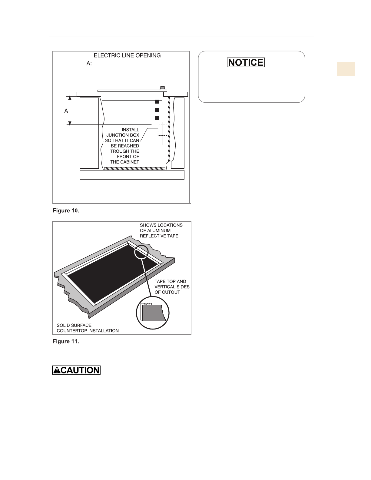
• For solid surface material installations such as Surel™ and Corian®, consult with solid surface
manufacturer. Apply heat reflective tape such as Scotch® Aluminum Foil Tape #425 or #427
around the cutout so that it folds over on the top and sides.
• Do not wrap the tape underneath the cooktop.
• Be sure the tape extends beyond the outermost flange of the cooktop. All corners should be
covered with tape.
 Loading...