

Hestan KDO30WH Installation Manual

INDOOR COOKING
Wall-Oven
KSO, KDO
Installation Manual
CAUTION
NOTICE
IF THE INFORMATION IN THIS MANUAL IS NOT FOLLOWED
EXACTLY, A FIRE OR EXPLOSION MAY RESULT CAUSING PROPERTY
DAMAGE, PERSONAL INJURY, OR DEATH.
Do not store or use gasoline or other flammable vapors and liquids in the vicinity of
this or any other appliance.
Installation and service must be performed by a qualified installer or service agency.
DO NOT REPAIR, REPLACE OR REMOVE ANY PART OF THE APPLIANCE UNLESS
SPECIFICALLY RECOMMENDED IN THE MANUAL. IMPROPER INSTALLATION,
SERVICE OR MAINTENANCE CAN CAUSE INJURY OR PROPERTY DAMAGE. REFER
TO THIS MANUAL FOR GUIDANCE. ALL OTHER SERVICING SHOULD BE DONE BY A
QUALIFIED TECHNICIAN.
READ THESE INSTRUCTIONS CAREFULLY AND COMPLETELY
BEFORE INSTALLING OR USING YOUR APPLIANCE TO REDUCE
THE RISK OF FIRE, BURN HAZARD, OR OTHER INJURY. KEEP
THIS MANUAL FOR FUTURE REFERENCE.
SAFETY DEFINITIONS
THIS INDICATES THAT DEATH OR SERIOUS INJURY MAY
OCCUR AS A RESULT OF NOT OBSERVING THIS WARNING
THIS INDICATES THAT MINOR OR MODERATE INJURY MAY
OCCUR AS A RESULT OF NOT OBSERVING THIS WARNING.
THIS INDICATES THAT DAMAGE TO THE APPLIANCE OR
PROPERTY MAY OCCUR AS A RESULT OF NOT OBSERVING
THIS WARNING.
INSTALLER: LEAVE THIS MANUAL WITH THE OWNER OF THE APPLIANCE.
HOMEOWNER: RETAIN THIS MANUAL FOR FUTURE REFERENCE.
TABLE OF CONTENTS
1 SAFETY PRECAUTIONS - BEFORE YOU BEGIN
2 MODEL NUMBERS
2 RATING LABEL
2 REGULATORY / CODE REQUIREMENTS
3 LOCATION AND INSTALLATION
9 ELECTRICAL CONNECTIONS
11 FINAL SETUP
11 SERVICE
SAFETY PRECAUTIONS - BEFORE YOU BEGIN
When properly cared for, your Hestan appliance will provide safe, reliable service for many
years. When using this appliance, basic safety practices must be followed as outlined below.
IMPORTANT: Save these instructions for the local Utility Inspector’s use.
EN
INSTALLER: Please leave these Installation Instructions with the owner.
OWNER: Please retain these Installation Instructions for future reference.
This appliance is NOT designed for installation in manufactured (mobile) homes or
recreational park trailers. Do NOT install this appliance outdoors.
ELECTRICAL SHOCK HAZARD
Disconnect power before installing or servicing appliance. Before turning
power ON, be sure all controls are in the OFF position. Failure to do so can
result in death or electrical shock.
ELECTRICAL GROUNDING
• This appliance must be grounded. Grounding reduces the risk of electric shock in the
event of a short circuit. Read the ELECTRICAL CONNECTIONS section of this manual
for complete instructions.
• DO NOT ground to a gas pipe.
• DO NOT use an extension cord with this appliance.
• DO NOT have a fuse in the NEUTRAL or GROUNDING circuit. A fuse in the NEUTRAL
or GROUNDING circuit could result in an electrical shock.
©2018 Hestan Commercial Corporation
1
MODEL NUMBERS
OVEN MODELS
EN
Model No. Description Circuit Breaker Req’d
KSO 30 30” Single Wall Oven 20 Amp
KDO 30 30” Double Wall Oven 40 Amp
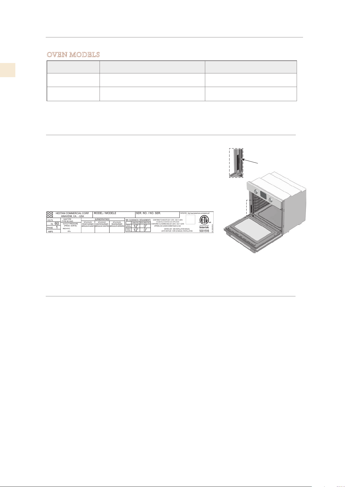
RATING LABEL
The rating label contains important information about your
Hestan appliance such as the model and serial number, electrical
rating and the minimum installation clearances.
The rating label is located on the left side of the oven cavity
opening near the door hinge.
If service is necessary, contact Hestan Customer Care with the
model and serial number information shown on the label.
RATING LABEL
TYPICAL RATING LABEL
REGULATORY / CODE REQUIREMENTS
Installation of this cooking appliance must be made in accordance with local codes. In the
absence of local codes, this unit should be installed in accordance with the National Electrical
Code and local codes.
This appliance must be electrically grounded in accordance with local codes or in the absence
of local codes with the National Electrical Code
CSA C22.1
.
ANSI/NFPA 70
, or Canadian Electrical code
2
©2018 Hestan Commercial Corporation
LOCATION AND INSTALLATION
NOTICE
UNPACKING AND PLACEMENT
Remove the outer carton and packing materials from the shipping pallet. Do not remove the
plastic film covering the stainless-steel surfaces. This film protects the finish from scratches
until the appliance is installed in its final position.
The unit is very heavy and should be handled with care. Use proper safety equipment, such as
gloves, and at least 2 persons to move the appliance into position to avoid injury and to avoid
damage to the floor or the appliance itself.
DO NOT USE A HAND TRUCK OR DOLLY ON THE FRONT OR REAR
OF THE OVEN. HANDLE AND MOVE FROM THE SIDES ONLY.
Do not lift or carry the appliance by the oven door or handle. This could damage the door
hinges. Use handles on either side of oven.
PREPARATION
Before moving the oven, protect any finished flooring and remove or secure the oven door(s)
closed to prevent damage. DO NOT lift the oven by the door handle. See “OVEN DOOR
REMOVAL” on page 4 regarding door removal.
An approved junction box is to be installed where it will be easily reached through the front of
the cabinet where the oven will be located. The oven has 3 ft. [91 cm] of conduit, an allowance
of 2 to 3 ft. [61-91 cm] of slack in the line is recommended for future relocation.
EN
The oven support surface must be a minimum 3/4” [2 cm] plywood platform.
For single ovens, it must support 202 pounds [92 kg].
For double ovens, it must support 379 pounds [172 kg].
The platform must be solid, level, and flush with the bottom of the cabinet cutout.
The oven should be located for convenient use in the kitchen, but away from strong drafts.
Drafts may be caused by open doors or windows, or by heating and/or air conditioning vents or
fans. Make sure that electrical power can be provided to the location selected.
TOOLS
The following tools are needed for the installation of the oven:
• Tape measure and straight edge or ruler
• Pencil
• Philips screw driver
• Level
• Wire cutters and wire stripper
• Hand or saber saw
• 1” [2.5 cm] Hole saw
• Drill and drill bit
• Safety gloves and goggles
• Volt meter [0-250VAC]
©2018 Hestan Commercial Corporation
3
EN
LOCATION AND INSTALLATION
(continued)
STEPS FOR INSTALLATION
The following pages provide the necessary information for proper installation of the oven and
are arranged as follows:
• Technical data (Electrical ratings and maximum connected load).
• Oven Door Removal - optional
• Installation cutout dimensions, required clearances and mounting instructions for:
- Wall or under-counter installation, single oven
- Wall installation, double oven
- Flush installation
• Electrical supply and wiring requirements, electrical connections for 3-wire or 4-wire branch
circuit. Programming required if connecting to 208 volt circuit.
• Final checklist.
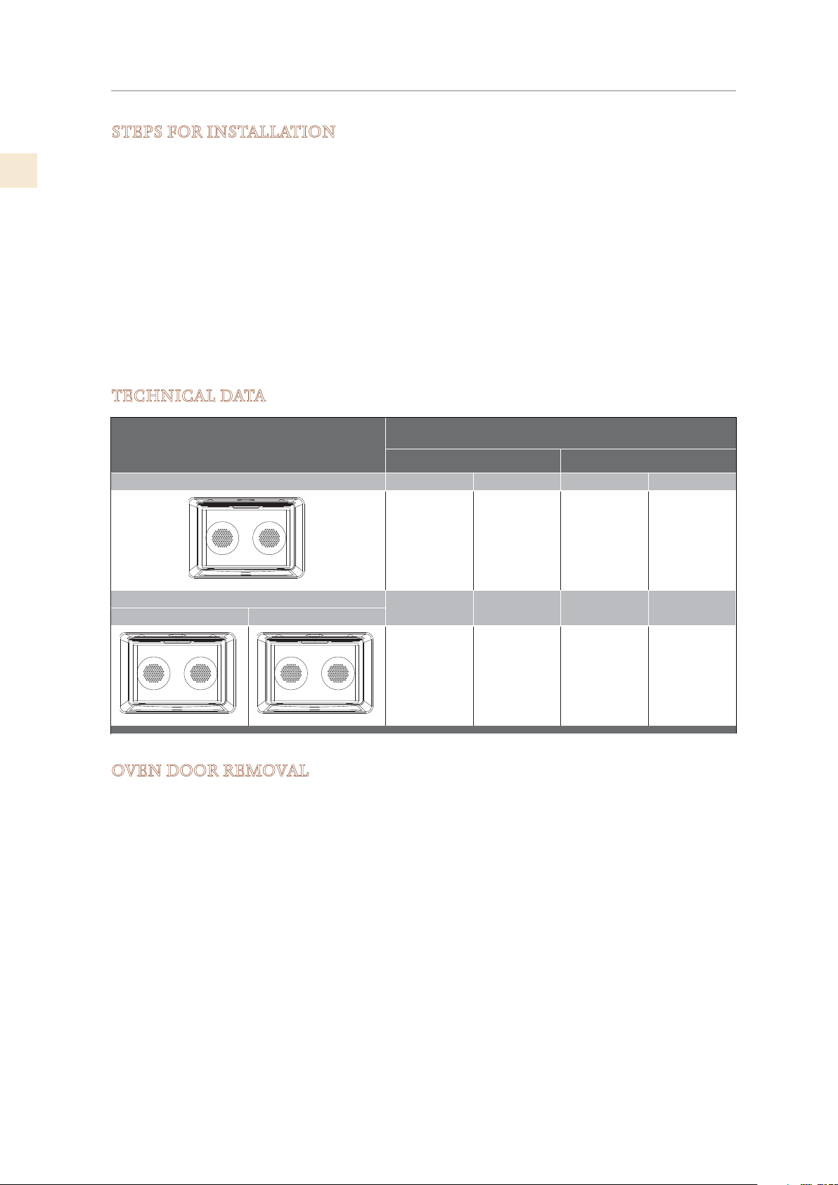
TECHNICAL DATA
Electrical Ratings and Maximum Connected Load
Oven Model
@ 120/240 Volts 60 Hz @ 120/208 Volts 60 Hz
SINGLE OVEN Amperes kW Amperes kW
16.9 3.84 17.5 3.54
DOUBLE OVEN
UPPER CAVITY LOWER CAVITY
Amperes kW Amperes kW
33.8 7.68 32.4 6.48
OVEN DOOR REMOVAL
To reduce weight during installation or to fit through a very narrow door opening, the oven
door(s) can be removed. Remove only if necessary.
Make sure oven is cool and power to the oven has been turned off before removing the door.
Failure to do so could result in electrical shock or burns.
• The oven door is heavy and fragile. Use both hands to remove the oven door. The door
front is glass. Handle carefully to avoid breakage.
• Grasp only the sides of the oven door. Do not grasp the handle as it may swing in your hand
and cause damage or injury.
• Failure to grasp the oven door firmly and properly could result in personal injury or product
damage.
4
©2018 Hestan Commercial Corporation
TO REPLACE THE DOOR
2
4
3
5
1
LOCATION AND INSTALLATION
(continued)
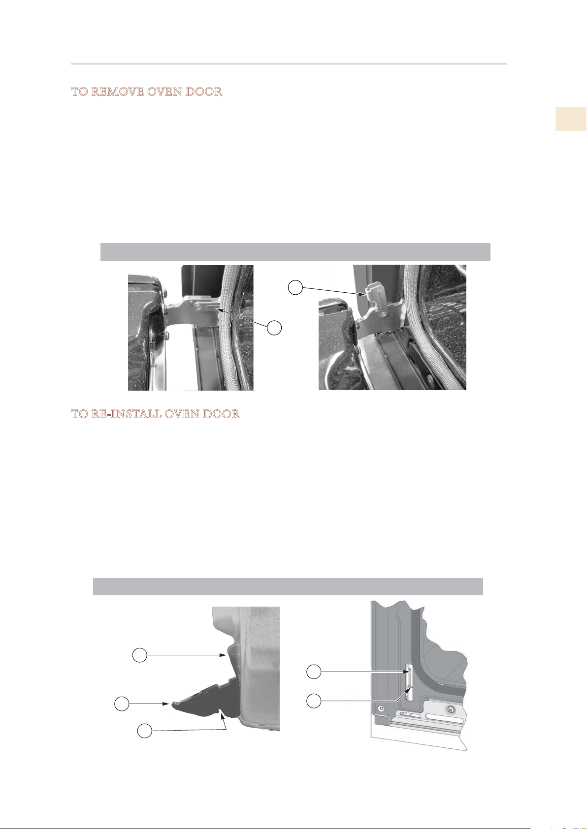
TO REMOVE OVEN DOOR
1. Open oven door completely.
2. At each hinge location, swing the hinge retainer (1) up until it stops. A screwdriver may be
needed to do this.
3. Gently close the oven door until it stops against the hinge retainers. It will be nearly closed
and the upper edge of the door will be slightly higher than the opening.
4. Hold on firmly to both sides of the door (not the handle) and pull the door straight up to
release the hinge arms, then pull the door away from the oven. Place the oven door in a
safe location until needed.
• NEVER release the hinge retainers and try to close the hinges. Doing so will snap the
hinges closed with great force which could cause injury.
EN
TO REMOVE THE DOOR
1
1
TO RE-INSTALL OVEN DOOR
1. Hold the door firmly on both sides (not from handle) at approximately 30° from the closed
position and insert the hinges into the slots (3) in the oven.
2. The bottom edge of each hinge (2) has a notch (4) which must engage on the lip (5). DO
NOT FORCE OR BEND OR TWIST THE DOOR!
3. Slowly open the door all the way.
4. Swing each hinge retainer (1) down until completely inside the slot opening and fully
seated. A screwdriver may help you do this. NOTE: The hinge retainer will not swing into
the slot opening unless the hinge arm is fully seated.
5. Gently close the oven door to check for smooth operation.
©2018 Hestan Commercial Corporation
5
EN
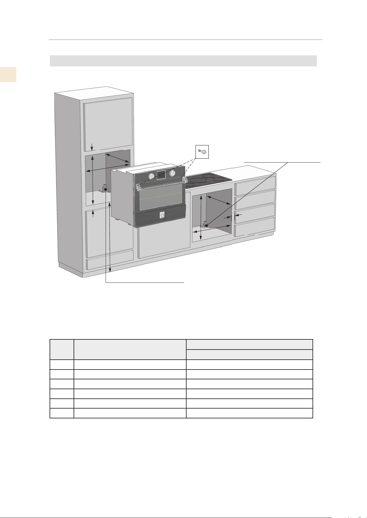
Screws should be inserted through the mounting holes in the positions
LOCATION AND INSTALLATION
WALL OR UNDER-COUNTER INSTALLATION, SINGLE OVEN
Secure oven to cabinet using the screws provided.
indicated in the frame (open door to see frame and mounting holes).
Do not over tighten screws.
F
B
A
C
(continued)
Electrical supply junction box
B
E
D
Electrical supply junction box
C
E
A
Ltr. DIMENSION SINGLE
30”
A Cutout Width 28 7/16” [72.2 cm]
B Cutout Depth 24” [61 cm]
C Cutout Height 27 3/8” [69.5 cm]
D Bottom of Cutout to finished floor 34” [86.5 cm] recommended
E Minimum Spacing 1/2” [1.3 cm]
F Minimum Spacing 3/4” [1.9 cm]
6
©2018 Hestan Commercial Corporation
LOCATION AND INSTALLATION
E
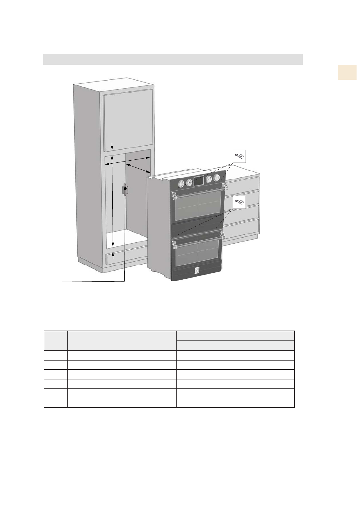
WALL INSTALLATION, DOUBLE OVEN
Secure oven to cabinet using the screws provided.
Screws should be inserted through the mounting holes
in the positions indicated in the frame (open door to see
frame and mounting holes).
Do not over tighten screws.
F
A
B
C
(continued)
EN
E
lectrical supply junction box
Ltr. DIMENSION DOUBLE
30”
A Cutout Width 28 7/16” [72.2 cm]
B Cutout Depth 24” [61 cm]
C Cutout Height 50” [127 cm]
D Bottom of Cutout to finished floor N/A
E Minimum Spacing 1/2” [1.3 cm]
F Minimum Spacing 1 1/4” [3.2 cm]
©2018 Hestan Commercial Corporation
7
 Loading...